EP3756059B1 - Drahtlose betätigungseinheit mit einem thermostatständer - Google Patents
Drahtlose betätigungseinheit mit einem thermostatständer Download PDFInfo
- Publication number
- EP3756059B1 EP3756059B1 EP18743177.0A EP18743177A EP3756059B1 EP 3756059 B1 EP3756059 B1 EP 3756059B1 EP 18743177 A EP18743177 A EP 18743177A EP 3756059 B1 EP3756059 B1 EP 3756059B1
- Authority
- EP
- European Patent Office
- Prior art keywords
- assembly
- rotatable
- cover
- smart home
- cover assembly
- Prior art date
- Legal status (The legal status is an assumption and is not a legal conclusion. Google has not performed a legal analysis and makes no representation as to the accuracy of the status listed.)
- Active
Links
Images


Classifications
-
- H—ELECTRICITY
- H01—ELECTRIC ELEMENTS
- H01H—ELECTRIC SWITCHES; RELAYS; SELECTORS; EMERGENCY PROTECTIVE DEVICES
- H01H19/00—Switches operated by an operating part which is rotatable about a longitudinal axis thereof and which is acted upon directly by a solid body external to the switch, e.g. by a hand
- H01H19/02—Details
- H01H19/10—Movable parts; Contacts mounted thereon
- H01H19/14—Operating parts, e.g. turn knob
-
- H—ELECTRICITY
- H01—ELECTRIC ELEMENTS
- H01H—ELECTRIC SWITCHES; RELAYS; SELECTORS; EMERGENCY PROTECTIVE DEVICES
- H01H13/00—Switches having rectilinearly-movable operating part or parts adapted for pushing or pulling in one direction only, e.g. push-button switch
- H01H13/02—Details
- H01H13/12—Movable parts; Contacts mounted thereon
- H01H13/14—Operating parts, e.g. push-button
-
- H—ELECTRICITY
- H01—ELECTRIC ELEMENTS
- H01H—ELECTRIC SWITCHES; RELAYS; SELECTORS; EMERGENCY PROTECTIVE DEVICES
- H01H13/00—Switches having rectilinearly-movable operating part or parts adapted for pushing or pulling in one direction only, e.g. push-button switch
- H01H13/02—Details
- H01H13/04—Cases; Covers
-
- H—ELECTRICITY
- H05—ELECTRIC TECHNIQUES NOT OTHERWISE PROVIDED FOR
- H05K—PRINTED CIRCUITS; CASINGS OR CONSTRUCTIONAL DETAILS OF ELECTRIC APPARATUS; MANUFACTURE OF ASSEMBLAGES OF ELECTRICAL COMPONENTS
- H05K5/00—Casings, cabinets or drawers for electric apparatus
- H05K5/02—Details
- H05K5/03—Covers
-
- H—ELECTRICITY
- H05—ELECTRIC TECHNIQUES NOT OTHERWISE PROVIDED FOR
- H05K—PRINTED CIRCUITS; CASINGS OR CONSTRUCTIONAL DETAILS OF ELECTRIC APPARATUS; MANUFACTURE OF ASSEMBLAGES OF ELECTRICAL COMPONENTS
- H05K5/00—Casings, cabinets or drawers for electric apparatus
- H05K5/10—Casings, cabinets or drawers for electric apparatus comprising several parts forming a closed casing
-
- F—MECHANICAL ENGINEERING; LIGHTING; HEATING; WEAPONS; BLASTING
- F24—HEATING; RANGES; VENTILATING
- F24D—DOMESTIC- OR SPACE-HEATING SYSTEMS, e.g. CENTRAL HEATING SYSTEMS; DOMESTIC HOT-WATER SUPPLY SYSTEMS; ELEMENTS OR COMPONENTS THEREFOR
- F24D19/00—Details
- F24D19/10—Arrangement or mounting of control or safety devices
-
- F—MECHANICAL ENGINEERING; LIGHTING; HEATING; WEAPONS; BLASTING
- F24—HEATING; RANGES; VENTILATING
- F24F—AIR-CONDITIONING; AIR-HUMIDIFICATION; VENTILATION; USE OF AIR CURRENTS FOR SCREENING
- F24F11/00—Control or safety arrangements
- F24F11/50—Control or safety arrangements characterised by user interfaces or communication
- F24F11/52—Indication arrangements, e.g. displays
-
- H—ELECTRICITY
- H01—ELECTRIC ELEMENTS
- H01H—ELECTRIC SWITCHES; RELAYS; SELECTORS; EMERGENCY PROTECTIVE DEVICES
- H01H2209/00—Layers
- H01H2209/002—Materials
-
- H—ELECTRICITY
- H01—ELECTRIC ELEMENTS
- H01H—ELECTRIC SWITCHES; RELAYS; SELECTORS; EMERGENCY PROTECTIVE DEVICES
- H01H2231/00—Applications
- H01H2231/012—Household appliance
-
- H—ELECTRICITY
- H01—ELECTRIC ELEMENTS
- H01H—ELECTRIC SWITCHES; RELAYS; SELECTORS; EMERGENCY PROTECTIVE DEVICES
- H01H3/00—Mechanisms for operating contacts
- H01H3/02—Operating parts, i.e. for operating driving mechanism by a mechanical force external to the switch
- H01H3/08—Turn knobs
-
- H—ELECTRICITY
- H05—ELECTRIC TECHNIQUES NOT OTHERWISE PROVIDED FOR
- H05K—PRINTED CIRCUITS; CASINGS OR CONSTRUCTIONAL DETAILS OF ELECTRIC APPARATUS; MANUFACTURE OF ASSEMBLAGES OF ELECTRICAL COMPONENTS
- H05K5/00—Casings, cabinets or drawers for electric apparatus
- H05K5/02—Details
- H05K5/0217—Mechanical details of casings
- H05K5/0221—Locks; Latches
Definitions
- HVAC control wires may be run from an HVAC system, behind a wall, and exposed in an inconvenient location, such as within a utility closet. Such a location may not be convenient to be accessed by a user or such a location may not be ideal for accurately sensing the temperature of a region of the structure in which occupants are typically present.
- EP 3 144 783 A1 relates to an operation knob and a display device in which same is used.
- US 2010/051430 A1 relates to a portable electronic device and a button assembly thereof.
- KR 2012 0029534 A relates to a rotary knob-integrated temperature-display module.
- WO-A-2015/148596 relates to an intelligent thermostat in a smart-home environment which includes a rotating cover fastened to a backplate.
- a smart home device is described as in claims 1-12.
- An actuator device may be connected with control wires.
- control wires may control operation of various components, such as: a furnace; a boiler; a fan; an air conditioner; and/or a multi-stage heating or cooling system.
- the actuator may open and close circuits in order to control operation of components of the HVAC system. Due to the actuator being directly connected with control wires, the actuator may be located in a hidden, concealed, or inconvenient location, such as in a utility closet, where the HVAC control wires are exposed.
- a user may have a thermostat and a movable stand device (also referred to as a "stand”) that can be connected to a power source near a location where the user desires the thermostat to be located.
- the user may typically have the thermostat located in a convenient location in a room frequently used by occupants of the structure.
- the stand is configured to connect with a thermostat and provide the thermostat with power and, possibly, temperature measurements.
- the thermostat wirelessly communicates with the actuator device in order to control the components of the HVAC system.
- the actuator can be directly connected to the control wires and the thermostat can be conveniently located to ensure that the temperature of a desired location is monitored accurately and to enable a user to easily access controls to control the HVAC.
- the thermostat may receive and implement temperature set-points provided by a user.
- the thermostat may further learn and/or receive a setpoint schedule to be implemented daily or on certain days of the week.
- the thermostat may communicate with a remote cloud-based server to provide users with various services via end-user computerized devices, such as a smartphone, desktop, or tablet computer.
- end-user computerized devices such as a smartphone, desktop, or tablet computer.
- end-user computerized devices such as a smartphone, desktop, or tablet computer.
- the actuator device is configured to control functions of the control system and may be located where the control wires for the control system are exposed.
- the system may additional comprises a remote device, such as a remote control device or a remote sensor or a remote input device, which remote device may include a door bell, camera, temperature sensor, smoke detector, carbon monoxide detectors, home assistants or other similar devices may located in a convenient location (e.g. in a room, within a building, outside of a building, on an entry way) and may wirelessly communicate with the actuator device in order to control the components of the control system.
- the remote device may be connected to a stand which is configured to provide power to the remote device.
- the actuator can be directly connected to the control wires whilst the remote device can be conveniently located to enable a user to easily access controls to control the control system via the actuator.
- Embodiments detailed herein are focused on various aspects of the actuator and stand. Such aspects can improve the functionality, aesthetics, sizing characteristics (e.g., allow the device to be thinner or smaller), and/or manufacturability of the actuator and/or the stand. It is to be appreciated that while one or more embodiments are described further herein in the context of a typical HVAC system used in a residential home, such as a single-family residential home, the scope of the present teachings is defined by the claims. More generally, intelligent thermostat systems according to one or more of the embodiments are applicable for a wide variety of enclosures having one or more HVAC systems including, without limitation, duplexes, townhomes, multi-unit apartment buildings, hotels, retail stores, office buildings, and industrial buildings.
- smart home environments may refer to smart environments for homes such as a single-family house, but the scope of the present teachings is defined by the claims, the present teachings being likewise applicable, without limitation, to duplexes, townhomes, multi-unit apartment buildings, hotels, retail stores, office buildings, industrial buildings, and more generally any living space or work space having one or more smart hazard detectors.
- FIG. 1 illustrates an embodiment of a block diagram of an HVAC control system 100 that includes a stand and an actuator.
- HVAC control system 100 may include: actuator device 110; mounting plate 120; HVAC system 130; thermostat 140; and stand device 150.
- Actuator device 110 may be attached to a mounting plate 120.
- Mounting plate 120 may facilitate actuator device 110 being attached to a surface (e.g., a wall) and allowing HVAC control wires to be routed into a back of actuator device 110.
- HVAC control wires may be mounted on a surface of a wall.
- Mounting plate 120 may allow actuator device 110 to be secured to the surface of the wall while allowing HVAC control wires to be passed through a rear surface of actuator device 110.
- Actuator device 110 may be connected via multiple HVAC control wires to HVAC system 130.
- Actuator device 110 may include: display 111, user interface 112, processing system 113, wireless interface 114, and control interface 115.
- Display 111 which may include one or more LEDs or other forms of lighting elements, may present information to a user.
- Display 111 may include a "dead front" display.
- a "dead front" display is a display that appears to have a blank display surface (e.g. that is difficult to identify as a display) when the one or more lighting elements are inactive. When active, the lighting elements light the display to make one or more images, such as symbols, text, particular region on the display, visible to the user on the display surface,.
- User interface 112 may include one or more buttons or other forms of user input devices that allow a user to provide input directly to actuator device 110.
- Stand device 150 may be placed on a surface and may have a power system 151 that powers thermostat 140.
- Power system 151 may be connected with a power outlet (e.g., 120 V, 230 V) and may output a constant voltage to thermostat 140.
- Stand device 150 may have one or more on-board sensors, such as temperature and/or humidity sensor 152, that provides temperature and/or humidity measurements to thermostat 140.
- FIG. 2 illustrates an exploded view of a top of an actuator 200.
- Actuator 200 can represent an embodiment of actuator device 110 of FIG. 1 .
- the following describes an actuator for controlling a HVAC system but, as discussed above, it is not intended to limit the features described herein only to an actuator for a HVAC control system. It will be appreciated that one or more features described herein may be used in actuators for controlling other control systems or in other smart home devices.
- the smart home device comprises actuator 200 which comprises a chassis assembly that defines one or more compartments and which comprises a plurality of cover fasteners.
- the actuator 200 further comprises a rotatable cover assembly configured to be removably attached with the plurality of cover fasteners to the chassis assembly to at least partially cover a front of the chassis assembly. While the rotatable cover assembly is removably attached with the plurality of cover fasteners, the rotatable cover assembly is configured to be rotatable with respect to the chassis assembly and while the rotatable cover is removably attached with the plurality of cover fasteners, the rotatable cover assembly is configured to block access to the one or more compartments defined by the chassis assembly.
- the one or more compartments of the chassis assembly are configured to support components of the actuator 200.
- the components of the actuator 200 may include one or more of:: chassis 210; display (not shown in FIG.
- Rotatable cover assembly 205 is designed to be facing away from a surface to which backplate 260 is mounted.
- rotatable cover assembly 205 when removably attached with chassis 210 of chassis assembly, may be the component of actuator 200 most visible to a user.
- Rotatable cover assembly 205 may be removable by a user, such as by pulling edges of rotatable cover assembly 205 to release the rotatable cover assembly from the plurality of cover fastener assemblies. Removing rotatable cover assembly 205 can allow a user to access wiring connectors and/or a battery compartment of chassis 210.
- a user can easily access the compartments of the chassis assembly to enable a user to more easily install the smart home device (e.g.
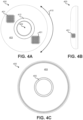
- Rotatable cover assembly 400 may be infinitely rotatable in a clockwise and counterclockwise rotation, such as illustrated by arrow 410. Rotatable cover assembly 400 may have no indexed locations, around chassis 210. After rotatable cover assembly 400 has been removably coupled with chassis 210, a user may rotate rotatable cover assembly 400 either clockwise or counterclockwise to a desired orientation. Once released, friction between rotatable cover assembly 400 and cover fastener assemblies 220 may hold rotatable cover assembly in the desired orientation.
- FIG. 4C a bottom of rotatable cover assembly 400 is illustrated.
- a bottom surface of cover body 403 may not be covered with fabric or screening and may instead be exposed plastic.
- Cover body 403 is rigid or semi-rigid such that fabric 401 conforms to an outer surface of cover body 403.
- Inner ring 405 may be used to fasten fabric 401 as part of rotatable cover assembly 400 in a stretched state.
- fabric 401 may be glued or otherwise affixed to cover body 403.
- one or more rings (e.g., inner ring 405) may be a stick-on label that serves to hide an edge of fabric 401 from viewing by a user. The use of such a ring may be primarily for aesthetic reasons.
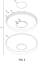
- FIG. 5 illustrates an exploded bottom view of rotatable cover assembly 400.
- inner ring 405 may be present, but not an outer ring.
- Rotatable cover assembly 400 may include: inner ring 405; cover body 403; and fabric 401.
- Fabric 401 may obtain the shape illustrated in FIG. 5 by being stretched over a top or front surface of cover body 403.
- Fabric 401 may be fastened or affixed (e.g., glued) to inner edge 501. After being fastened or affixed to inner edge 501, fabric 401 may be trimmed along the fastened or affixed edge such that a roughly even edge with minimal or limited fraying is present.
- Fabric 401 may further be stretched through open region 402 and fastened to inner ring surface 502.
- Inner ring 405 may be fastened or affixed (e.g., glued) to inner ring surface 502 such that an edge of fabric 401 is secured by inner ring 405 to inner ring surface 502 and hidden from view.
- a user when desiring to attach rotatable cover assembly 400 to the chassis assembly does not need to attempt to align protrusions of the cover fastener assemblies with any particular part of circular track 503.
- the protrusions of the cover fastener assemblies and the lips of the circular track 503 are configured to co-operate so as to facilitate the rotation of the rotatable cover assembly with respect to the chassis assembly when the rotatable cover assembly is attached to the chassis assembly whilst enabling easy removal by a user of the rotatable cover assembly from the chassis assembly regardless of the rotational orientation of rotatable cover assembly 400 with respect to chassis assembly 700.
- Friction can be present between cover fastener assemblies 220 and circular track 503 such that when a user is not twisting rotatable cover assembly 400 with respect to chassis 210, rotatable cover assembly 400 orientation remains static.
- FIG. 6 illustrates an embodiment of cover body 403.
- Cover body 403 may be formed or made from a rigid or semi-rigid material, such as plastic or metal.
- cover body 403 is injection molded.
- a top surface of cover body 403 may have a texture, such as indicated by raised protrusions 602 in magnified region 601.
- raised protrusions 602 are rectangular pyramids, triangular pyramids, or some other raised pyramidal structure.
- raised protrusions 602 may be randomly chemically etched.
- Raised protrusions 602 may cover an outer or top surface of cover body 403. Raised protrusions 602 may serve multiple purposes.
- raised protrusions 602 may provide friction and help keep fabric 401 in place. For instance, if a user applies lateral pressure to fabric 401 while fabric 401 is wrapped over the top surface of cover body 403, raised protrusions 602 may help prevent fabric 401 from further stretching and/or bunching. Additionally or alternatively, raised protrusions may increase or otherwise alter the textural feel of fabric 401 when fabric 401 is stretched and wrapped over the top surface of cover body 403.
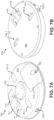
- FIG. 7A illustrates a top (or front) view of an embodiment of chassis assembly 700.
- FIG. 7B illustrates a bottom (or back) view of an embodiment of chassis assembly 700.
- Chassis assembly 700 may include chassis 210, wiring connector cover 215, cover fastener assemblies 220, button 702, and backplate 260.
- wiring connector cover 215 may be a leashed cover.
- cover leash 704. This may allow a user to access terminals present within an wiring compartment to allow control wires, such as HVAC control wires, to be attached and detached. Control wires may be routed through rear opening 703 into the wiring compartment that is covered from a front by wiring connector cover 215. By virtue of cover leash 704 being used to permanently secure wiring connector cover 215 to chassis 210, the loss of wiring connector cover 215 may be prevented.
- Button 702 may function as both a display and a user-pressable button that allows direct control of a control system, such as a HVAC system, at actuator 200 by a user. For instance, a user may press button 702 to manually activate one or more HVAC systems (e.g., a boiler).
- a control system such as a HVAC system
- a user may press button 702 to manually activate one or more HVAC systems (e.g., a boiler).
- a protruding slider of cover fastener assemblies 220 may protrude through chassis 210.
- Cover fastener assemblies 220 may be fastened to chassis 210 and may be made of a semi rigid material that can flex inward when pressure is applied to a protruding slider of each cover fastener assembly. Pressure applied to a protruding slider of cover fastener assemblies 220 may cause the protruding slider to at least partially retract to within chassis 210.
- Each protruding slider may be tapered on a top and bottom side to allow the slider to retract when rotatable cover assembly 205 is pushed onto or pulled off of chassis assembly 700.
- the protruding sliders of cover fastener assemblies 220 may rest in a fully or partially extended state within circular track 503 of cover body 403 when rotatable cover assembly 400 is attached with chassis 210.
- the protruding sliders of cover fastener assemblies 220 can allow for rotatable cover assembly 400 to be rotated and oriented into any desirable orientation, such that a texture or grain of fabric 401 is aligned with objects or surfaces in the environment of the actuator.
- cover body 403 is pulled away from chassis 210 or when cover body 403 is pushed onto chassis 210, the protruding sliders of cover fastener assemblies 220 may retract to allow for coupling and decoupling. While two cover fastener assemblies are illustrated as present on chassis assembly 700, it should be understood that fewer or greater numbers of cover fastener assemblies 220 may be present in other embodiments.
- Fastener pass-throughs 707 may allow for fasteners to be installed through a front of chassis 210 to attach backplate 260 to a surface, such as a wall. By virtue of chassis 210 being fastened to backplate 260, chassis 210 is also fastened to the surface. Fasteners may attach with a surface through fastener openings 706 (706-1, 706-2). Fastener pass-throughs 707 may allow for a screw driver or other installation tool to be used to attach fasteners, such as screws, through chassis 210 to backplate 260.
- Backplate 260 may have a flat exterior surface to permit backplate 260 to be attached flush to a surface, such as a wall. Such attachment may occur over a location where control wires, such as HVAC control wires, pass through an opening in a wall.
- chassis 210 of chassis assembly 700 may be used to house one or more batteries, such as batteries 265.
- batteries 265 may be partially visible.
- Battery holder tab 701 may help keep batteries in position within battery compartment 710 such that the batteries properly contact spring cap 242, spring cap 244, battery contact 240, and battery contact 245 when rotatable cover assembly 205 is attached with chassis assembly 700.
- a back surface of battery holder tab 701 may be made of a flexible material and may be curved to roughly match a curvature of cylindrical batteries that are to be installed in battery compartment 710; the inner surface of rotatable cover assembly 205 may keep battery holder tab 701 pressed against the batteries and in a proper position within battery compartment 710.
- Battery holder tab 701 may be connected to a flexible ribbon leash 711.
- Ribbon leash 711 may serve multiple purposes. First, ribbon leash 711 may help prevent battery holder tab 701 from being lost by battery holder tab 701 being permanently attached to battery holder tab 701 and to chassis 210.
- battery holder tab 701 When battery holder tab 701 is pulled by a user, ribbon leash 711 may push batteries out of battery compartment 710 due to ribbon leash 711 residing under batteries 265 when batteries 265 are installed in battery compartment 710. Therefore, battery holder tab 701 and attached battery ribbon leash 711 may function together as a single structure to both: 1) hold batteries in place within battery compartment 710; and 2) help remove batteries from battery compartment 710. It should be understood that battery holder tab 701 and ribbon leash 711 may be adapted for use with fewer or greater numbers of batteries.
- FIG. 7C illustrates a front view of an embodiment of chassis assembly 700 with wiring connector cover 215 in an open position.
- terminals 720 e.g., 720-1, 720-2, 720-3, 720-4, and 720-5
- control wires such as HVAC control wires
- chassis assembly 700 is mounted to a wall, wiring connector cover 215 can be hung in an open position. In such a position, it may be possible to attach rotatable cover assembly 205 to chassis assembly 700.
- Cover leash 704 may be rubber or some other flexible or semi-rigid material. When wiring connector cover 215 is closed, access to terminals 720 is prevented and cover leash 704 may be stored within control wire compartment 725.
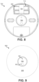
- FIG. 8 illustrates a front view of chassis assembly 700 with rotatable cover assembly 205 removed.
- batteries 265 when installed, reside below battery holder tab 701, but above ribbon leash 711. Therefore, when battery holder tab 701 is pulled away from chassis 210, ribbon leash 711 will extend away from battery compartment 710 and will push batteries 265 from battery compartment 710.
- Dead front display 702 may function as a display and as a button (button 702).
- FIG. 9 illustrates a front view of actuator 200 in which rotatable cover assembly 205 is removably attached with chassis assembly 700. When rotatable cover assembly 205 is attached with chassis assembly 700, dead front display 702 remains exposed and visible. Dead front display 702 may appear to have a blank display surface when no internal light behind the dead front display surface is illuminated. Region 901 or region 902 may be at least partially illuminated from within chassis assembly 700 when one or both of the internal lights are illuminated. Various graphics, numbers, or letters may be illuminated by etching such graphics, numbers, or letters into a layer of regions 901 and 902.
- dead front display 702 may be movable with respect to the opening in the rotatable cover assembly 205.
- a user may press dead front display 702 such that dead front display 702 depresses a distance and functions as a button.
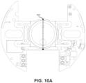
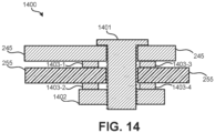
- FIG. 10A illustrates a top view of an embodiment of a button, rubber boot assembly, a light pipe assembly, and a PCB.
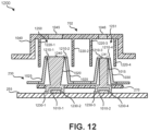
- FIG. 10A illustrates a location of cross-section 1000. The location of cross-section 1000 may also be indicative of the location of cross-section 1100 of FIG. 11 and 1200 of FIG. 12 .
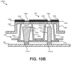
- FIG. 10B illustrates a cross-section 1000 of button 702, light boot assembly 230, light pipe assembly 270, and PCB 255.
- two lighting elements which may be LEDs, are mounted on PCB 255: lighting element 1010-1 and lighting element 1010-2. Lighting element 1010-1, when active, emits light into light pipe 1020 of light pipe assembly 270.
- Lighting element 1010-2 when active, emits light into light pipe 1015 of light pipe assembly 270.
- Light pipes 1020 and 1015 may have different shapes to illuminate different sizes of graphics, icons, text, or numbers on button 702. For instance, light pipe 1020 may have a wider top than light pipe 1015 to accommodate even illumination of a larger graphic on button 702.
- Light pipes 1020 and 1015 may be made from a transparent or translucent material, such as glass or clear plastic. Due to the refraction index between air and the transparent or translucent material of light pipes 1020 and 1015, most light emitted by lighting elements 1010 may be internally reflected within light pipes 1015 and 1020 and emitted from front surfaces 1011-1 and 1011-2.
- Rubber boot 1025 may be opaque and prevent stray light from light pipe 1020 (e.g., light emitted from a side of light pipe 1020) or light from lighting element 1010-1 from inadvertently allowing reflected light to exit the actuator.
- Rubber boot 1030 may also be opaque and prevent stray light from light pipe 1015 (e.g., light emitted from a side of light pipe 1015) or light from lighting element 1010-2 that did not enter light pipe 1015 from inadvertently allowing reflected light to exit the actuator.
- button 702 When button 702 is depressed, light pipes 1020 and 1015 may be unaffected, but rubber boots 1025 and 1030 may be partially compressed or deformed.
- rubber boots 1025 and 1030 While being compressed or deformed, rubber boots 1025 and 1030 may continue to block light from being reflected to an undesired location.
- rubber boots 1025 and 1030 may be formed from some other flexible or semi-flexible material.
- rubber boots 1025 and 1030 may be located at least a distance from button 702 such that when button 702 is depressed, button 702 does not touch rubber boots 1025 or 1030.
- Such an arrangement may permit rubber boots 1025 or 1030 to be formed from a rigid or semi-rigid material, such as plastic or metal.
- Button 702 may include body 1040, which may be formed from an opaque material, such as plastic or metal. Body 1040 may have regions, such as region 1045 and region 1046, that are filled with a translucent or transparent material, such as plastic or glass. Regions 1045 and 1046 can refer, for example, to regions 902 and 901, respectively, of FIG. 9 .
- a coat of opaque paint 1050 which may be black, may be applied. This opaque paint may block light from being emitted through a front of body 1040. A portion of this opaque paint 1050 may be removed, such as via laser etching, to form one or more graphics, icons, letters, or numbers over regions 1045 and 1046.
- the front surface, over the coat of opaque paint 1050 and etched portions, may be coated with semi-transparent paint 1055, which may be gray or some other color. Semi-transparent paint 1055 may allow light to be passed through in regions 1060 where the semi-transparent paint is affixed directly to regions 1045 and 1046.
- cross-section 1000 illustrates two light pipes 1020 and 1015, which are of different shapes, it should be understood that cross-section 1000 is merely an example. In other embodiments, greater or fewer numbers of light pipes may be present. Further, the light pipes may be of the same shape or various other shapes.
- Light pipe extensions 1230 in combination with a lower surface of light pipes 1015 and 1020, partially enclose lighting elements 1010.
- light pipe extensions 1230-1 and 1230-2 may be part of a single continuous structure that encircles lighting element 1010-1.
- light pipe extensions 1230-3 and 1230-4 may be part of a single continuous structure that encircles lighting element 1010-2.
- light pipe extensions 1230 may touch PCB 255 to increase the collection of light emitted from lighting elements 1010.
- light boot assembly 230 may contact light pipes 1015 and 1020 at an edge of light pipe top surfaces 1240 and 1241.
- rubber boot 1025 may contact light pipe 1020. This arrangement may help prevent light emitted from sides of light pipe 1020 other than top surface 1240 from escaping from the actuator device.
- rubber boot 1030 may contact light pipe 1015. This arrangement may help prevent light emitted from sides of light pipe 1020 other than top surface 1240 from escaping from the actuator device. While two contact points are illustrated for each of light pipes 1015 and 1020, it should be understood that this is due to a cross-section being illustrated in embodiment 1200. It should be understood that rubber boot 1025 may contact and encircle top surface 1240. Similarly, rubber boot 1030 may contact and encircle an edge of top surface 1241.
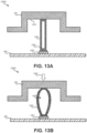
- cavity 1303 may grow in volume by one or more walls of compressible extension 1302 flexing outward. (If cavity 1303 is enclosed, one or more pressure-compensating holes may be present to allow air to enter and leave cavity 1303.) If cavity 1303 is not enclosed, but rather multiple supports make up compressible extension 1302, these supports may flex outward from a relaxed or extended position. When pressure is stopped being applied to button 702, button 702 will move away from PCB 255 and compressible extension 1302 will return to the relaxed or extended position of FIG. 13A . Such embodiments may decrease the manufacturing cost of the actuator by allowing switch 1301 to be mounted in a fixed location on PCB 255, but still help prevent damage to PCB 255 and/or switch 1301 if undue pressure is applied to button 702.
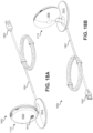
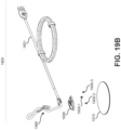
- FIGS. 18A and 18B illustrate an embodiment of stand assembly 1800 that includes stand device 1710 connected with cable 1801 (and without the thermostat (or other smart home device)).
- Cable 1801 may be a universal serial bus (USB) cable (or some other form of cable) that is being used to supply a thermostat that is connected with connector 1810 with power.
- USB connector 1802 may be connected to a power supply or other device that supplies an appropriate direct current voltage.
- Cable 1801 may be permanently connected with base 1815.
- Connector 1810 may be electrically connected to cable 1801 in order to provide a connected thermostat (or other form of smart home device) with power.
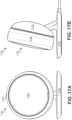
- Stand face 1805 may be a flat or nearly flat surface that allows a thermostat to sit flush on stand device 1710, as illustrated in FIGS 17A and 17B .
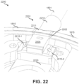
- FIG. 22 illustrates a detailed image of an embodiment 2200 of a connection region between a cable and a base of a stand assembly.
- cable 1810 has an overmold that serves to anchor cable 1801 with base 1815.
- Overmold 2201 may provide strain relief, such that force applied to pulling cable 1801 does not result in force being applied to the wires or contact of cable 1801 where connected with PCB 255. Rather than a hole being present in base 1815 through which cable 1801 passes, slot 2202 is present in base 1815 into which overmold 2201 is inserted prior to baseplate 1910 being attached to base 1815.
- Overmold 2201 may include portion 2210, base edge portion 2211, overmold body 2205, and overmold extensions 2215 (2215-1 and 2215-2).
Landscapes
- Engineering & Computer Science (AREA)
- Microelectronics & Electronic Packaging (AREA)
- Air Conditioning Control Device (AREA)
- Casings For Electric Apparatus (AREA)
Claims (13)
- Smart-Home-Vorrichtung (110; 200), umfassend:eine Fahrgestell-Baugruppe (210; 700), die ein oder mehrere Fächer (710, 725) definiert, und die Fahrgestell-Baugruppe umfasst eine Vielzahl von Abdeckungsbefestigungen (220);eine drehbare Abdeckungsbaugruppe (205; 400), die dazu konfiguriert ist, mit der Vielzahl von Abdeckungsbefestigungen (220) abnehmbar an der Fahrgestell-Baugruppe (210; 700) befestigt zu werden, um zumindest teilweise eine Vorderseite der Fahrgestell-Baugruppe (210; 700) abzudecken, wobei die drehbare Abdeckungsbaugruppe (205; 400) dazu konfiguriert ist, in Bezug auf die Fahrgestell-Baugruppe (210; 700) drehbar zu sein, während die drehbare Abdeckungsbaugruppe (205; 400) abnehmbar mit der Vielzahl von Abdeckungsbefestigungen (220) befestigt ist, dadurch gekennzeichnet, dass:die drehbare Abdeckungsbaugruppe (205; 400) dazu konfiguriert ist, in jeder beliebigen Drehorientierung an der Fahrgestell-Baugruppe (210; 700) angebracht und von ihr abgenommen zu werden; undwährend die drehbare Abdeckungsbaugruppe (205; 400) mit der Vielzahl von Abdeckungsbefestigungen (220) abnehmbar befestigt ist, die drehbare Abdeckungsbaugruppe (205; 400) dazu konfiguriert ist, den Zugang zu dem einen oder den mehreren Fächern (710, 725), die durch die Fahrgestell-Baugruppe (210; 700) definiert sind, zu blockieren.
- Smart-Home-Vorrichtung nach Anspruch 1, wobei, während die drehbare Abdeckungsbaugruppe (205; 400) mit der Vielzahl von Abdeckungsbefestigungen (220) abnehmbar befestigt ist, die drehbare Abdeckungsbaugruppe (205) dazu konfiguriert ist, in Bezug auf die Fahrgestell-Baugruppe (210; 700) drehbar zu sein.
- Smart-Home-Vorrichtung nach Anspruch 1, wobei die drehbare Abdeckungsanordnung (400) einen Abdeckungskörper (403) umfasst, wobei eine vordere Oberfläche des Abdeckungskörpers (403) eine Vielzahl von Vorsprüngen (602) umfasst.
- Smart-Home-Vorrichtung nach Anspruch 3, wobei die drehbare Abdeckungsbaugruppe (400) ferner einen Stoff (401) umfasst, der die vordere Oberfläche des Abdeckungskörpers (403) bedeckt, der die Vielzahl von Vorsprüngen (602) umfasst.
- Smart-Home-Vorrichtung nach Anspruch 1, wobei eine Vorderseite der drehbaren Abdeckungsbaugruppe (400) ein sichtbares Muster aufweist.
- Smart-Home-Vorrichtung nach Anspruch 5, wobei die Vorderseite der drehbaren Abdeckungsanordnung (400), die das sichtbare Muster aufweist, einen Stoff (401) umfasst.
- Smart-Home-Vorrichtung nach Anspruch 1, wobei die drehbare Abdeckungsanordnung (205; 400) kreisförmig ist.
- Smart-Home-Vorrichtung nach Anspruch 7, wobei die drehbare Abdeckungsbaugruppe (205; 400) mit nicht indexierter Bewegung kontinuierlich im Uhrzeigersinn und gegen den Uhrzeigersinn drehbar ist.
- Smart-Home-Vorrichtung nach Anspruch 1, wobei die Fahrgestell-Baugruppe (700) ein Display (702) umfasst, das durch eine definierte Öffnung (402) in der drehbaren Abdeckungsbaugruppe (205; 400) sichtbar ist, während die drehbare Abdeckungsbaugruppe (205; 400) mit der Vielzahl von Abdeckungsbefestigungen (220) abnehmbar befestigt ist.
- Smart-Home-Vorrichtung nach Anspruch 9, wobei das Display (702) ein Dead-Front-Display ist.
- Smart-Home-Vorrichtung nach Anspruch 1, wobei die Fahrgestell-Baugruppe (700) eine Taste (702) umfasst, die durch eine definierte Öffnung (402) in der drehbaren Abdeckungsbaugruppe (205; 400) zugänglich ist, während die drehbare Abdeckungsbaugruppe (205; 400) mit der Vielzahl von Abdeckungsbefestigungen (220) abnehmbar befestigt ist.
- Smart-Home-Vorrichtung nach Anspruch 1, wobei die Smart-Home-Vorrichtung (110; 200) eine Betätigungsvorrichtung ist, die dazu konfiguriert ist, über Anschlüsse (720), die in einem Fach (725) des einen oder der mehreren Fächer (710, 725) vorhanden sind, mit einer Vielzahl von Heizungs-, Lüftungs- und Klimatisierungssteuerungsdrähten verbunden zu sein.
- Heizkesselsteuerungssystem (100), umfassend:eine Smart-Home-Vorrichtung (110; 200) nach einem der vorhergehenden Ansprüche, wobei die Smart-Home-Vorrichtung eine Betätigungsvorrichtung (110; 200) umfasst, die über eine oder mehrere Steuerdrähte mit einem Heizkessel (130) verbunden ist, undeine Thermostatständervorrichtung (150; 1710), die einen Thermostat (140; 1705) mit Strom versorgt, der drahtlos mit der Betätigungsvorrichtung (110; 200) kommuniziert.
Applications Claiming Priority (1)
| Application Number | Priority Date | Filing Date | Title |
|---|---|---|---|
| PCT/US2018/039513 WO2020005210A1 (en) | 2018-06-26 | 2018-06-26 | Wireless actuator unit with a thermostat stand |
Publications (2)
| Publication Number | Publication Date |
|---|---|
| EP3756059A1 EP3756059A1 (de) | 2020-12-30 |
| EP3756059B1 true EP3756059B1 (de) | 2025-06-25 |
Family
ID=62976181
Family Applications (1)
| Application Number | Title | Priority Date | Filing Date |
|---|---|---|---|
| EP18743177.0A Active EP3756059B1 (de) | 2018-06-26 | 2018-06-26 | Drahtlose betätigungseinheit mit einem thermostatständer |
Country Status (3)
| Country | Link |
|---|---|
| US (1) | US12074003B2 (de) |
| EP (1) | EP3756059B1 (de) |
| WO (1) | WO2020005210A1 (de) |
Families Citing this family (3)
| Publication number | Priority date | Publication date | Assignee | Title |
|---|---|---|---|---|
| US20220075261A1 (en) * | 2020-09-10 | 2022-03-10 | Bugeye Technologies, Inc. | Light panel display |
| US20230266036A1 (en) * | 2022-02-18 | 2023-08-24 | Ryan Irons | Universal adapting device for retrofitting a thermostat system and methods of using the same |
| USD1090567S1 (en) * | 2022-03-21 | 2025-08-26 | Alfred Kaercher Se & Co. Kg | Circular controls surrounding a display screen |
Citations (4)
| Publication number | Priority date | Publication date | Assignee | Title |
|---|---|---|---|---|
| US3541882A (en) * | 1968-12-31 | 1970-11-24 | Perkin Elmer Corp | Electrically insulating knobs |
| US3662618A (en) * | 1969-05-31 | 1972-05-16 | Int Standard Electric Corp | Instrument knob having integral detent mechanism and panel mount socket means |
| KR20120029543A (ko) * | 2010-09-17 | 2012-03-27 | 김지영 | 이동통신 단말기의 보호커버 |
| WO2015148596A1 (en) * | 2014-03-28 | 2015-10-01 | Google Inc. | User-relocatable self-learning environmental control device |
Family Cites Families (13)
| Publication number | Priority date | Publication date | Assignee | Title |
|---|---|---|---|---|
| CA2584488A1 (en) * | 2006-04-06 | 2007-10-06 | Streetlight Intelligence, Inc. | Electronics enclosure and associated mounting apparatus |
| TW201009866A (en) * | 2008-08-27 | 2010-03-01 | Pegatron Corp | Portable electronic apparatus and key assembly thereof |
| KR20120029534A (ko) * | 2010-09-17 | 2012-03-27 | 현대모비스 주식회사 | 온도표시모듈 일체형 로터리 노브 |
| US9030829B2 (en) * | 2012-10-22 | 2015-05-12 | Oliver Joen-An Ma | Modular accessory |
| US9877580B2 (en) * | 2013-03-14 | 2018-01-30 | Rgb Systems, Inc. | Suspended ceiling-mountable enclosure |
| US11121527B2 (en) * | 2013-07-31 | 2021-09-14 | Briggs & Stratton, Llc | Meter socket adapter with integral automatic transfer switch |
| US10270236B2 (en) * | 2013-08-14 | 2019-04-23 | Wirepath Home Systems, Llc | Recessed equipment boxes and related assemblies and methods |
| EP3144783A4 (de) | 2014-05-15 | 2017-08-02 | Panasonic Intellectual Property Management Co., Ltd. | Bedienknopf und anzeigevorrichtung mit verwendung davon |
| US10478668B2 (en) * | 2014-11-24 | 2019-11-19 | Adidas Ag | Activity monitoring base station |
| US20170059900A1 (en) * | 2015-08-26 | 2017-03-02 | Google Inc. | Thermostat electronic display and lensing element therefor |
| US10356948B2 (en) * | 2015-12-31 | 2019-07-16 | DISH Technologies L.L.C. | Self-adjustable heat spreader system for set-top box assemblies |
| US11209845B2 (en) * | 2016-03-17 | 2021-12-28 | Jean-Louis Iaconis | Modular wall-mounted electrical control device |
| US11178939B2 (en) * | 2019-02-01 | 2021-11-23 | Axon Enterprise, Inc. | Systems and methods for adjustable mounting |
-
2018
- 2018-06-26 US US16/975,656 patent/US12074003B2/en active Active
- 2018-06-26 EP EP18743177.0A patent/EP3756059B1/de active Active
- 2018-06-26 WO PCT/US2018/039513 patent/WO2020005210A1/en not_active Ceased
Patent Citations (4)
| Publication number | Priority date | Publication date | Assignee | Title |
|---|---|---|---|---|
| US3541882A (en) * | 1968-12-31 | 1970-11-24 | Perkin Elmer Corp | Electrically insulating knobs |
| US3662618A (en) * | 1969-05-31 | 1972-05-16 | Int Standard Electric Corp | Instrument knob having integral detent mechanism and panel mount socket means |
| KR20120029543A (ko) * | 2010-09-17 | 2012-03-27 | 김지영 | 이동통신 단말기의 보호커버 |
| WO2015148596A1 (en) * | 2014-03-28 | 2015-10-01 | Google Inc. | User-relocatable self-learning environmental control device |
Also Published As
| Publication number | Publication date |
|---|---|
| US20200411256A1 (en) | 2020-12-31 |
| WO2020005210A1 (en) | 2020-01-02 |
| EP3756059A1 (de) | 2020-12-30 |
| US12074003B2 (en) | 2024-08-27 |
Similar Documents
| Publication | Publication Date | Title |
|---|---|---|
| AU2020244598B2 (en) | Consumer product system | |
| US10627791B2 (en) | Thermostat user interface | |
| US11371545B2 (en) | Adjustable-angle mounting system for hazard detector | |
| US9465407B2 (en) | Controller with dynamically indicated input devices | |
| US20180181291A1 (en) | Thermostat with wiring terminals configured for spatial compactness and ease of wire installation | |
| EP3756059B1 (de) | Drahtlose betätigungseinheit mit einem thermostatständer | |
| US20190042000A1 (en) | Smart switch | |
| US20130301224A1 (en) | Intelligent wall-mounted switch module | |
| WO2015187491A1 (en) | Light control unit with detachable electrically communicative faceplate | |
| US9786452B2 (en) | Modular switching system and method | |
| US10066848B1 (en) | Illuminating substrate-mountable devices | |
| JP2018028997A (ja) | 平面スイッチ | |
| CN110708805A (zh) | 一种智能家居挂杆系统 | |
| CN102099630A (zh) | 具有气象站和照明装置的空气调节器 |
Legal Events
| Date | Code | Title | Description |
|---|---|---|---|
| STAA | Information on the status of an ep patent application or granted ep patent |
Free format text: STATUS: UNKNOWN |
|
| STAA | Information on the status of an ep patent application or granted ep patent |
Free format text: STATUS: THE INTERNATIONAL PUBLICATION HAS BEEN MADE |
|
| PUAI | Public reference made under article 153(3) epc to a published international application that has entered the european phase |
Free format text: ORIGINAL CODE: 0009012 |
|
| STAA | Information on the status of an ep patent application or granted ep patent |
Free format text: STATUS: REQUEST FOR EXAMINATION WAS MADE |
|
| 17P | Request for examination filed |
Effective date: 20200921 |
|
| AK | Designated contracting states |
Kind code of ref document: A1 Designated state(s): AL AT BE BG CH CY CZ DE DK EE ES FI FR GB GR HR HU IE IS IT LI LT LU LV MC MK MT NL NO PL PT RO RS SE SI SK SM TR |
|
| AX | Request for extension of the european patent |
Extension state: BA ME |
|
| DAV | Request for validation of the european patent (deleted) | ||
| DAX | Request for extension of the european patent (deleted) | ||
| STAA | Information on the status of an ep patent application or granted ep patent |
Free format text: STATUS: EXAMINATION IS IN PROGRESS |
|
| 17Q | First examination report despatched |
Effective date: 20220808 |
|
| GRAP | Despatch of communication of intention to grant a patent |
Free format text: ORIGINAL CODE: EPIDOSNIGR1 |
|
| STAA | Information on the status of an ep patent application or granted ep patent |
Free format text: STATUS: GRANT OF PATENT IS INTENDED |
|
| INTG | Intention to grant announced |
Effective date: 20250131 |
|
| GRAS | Grant fee paid |
Free format text: ORIGINAL CODE: EPIDOSNIGR3 |
|
| GRAA | (expected) grant |
Free format text: ORIGINAL CODE: 0009210 |
|
| STAA | Information on the status of an ep patent application or granted ep patent |
Free format text: STATUS: THE PATENT HAS BEEN GRANTED |
|
| AK | Designated contracting states |
Kind code of ref document: B1 Designated state(s): AL AT BE BG CH CY CZ DE DK EE ES FI FR GB GR HR HU IE IS IT LI LT LU LV MC MK MT NL NO PL PT RO RS SE SI SK SM TR |
|
| P01 | Opt-out of the competence of the unified patent court (upc) registered |
Free format text: CASE NUMBER: APP_23703/2025 Effective date: 20250519 |
|
| REG | Reference to a national code |
Ref country code: GB Ref legal event code: FG4D |
|
| REG | Reference to a national code |
Ref country code: CH Ref legal event code: EP |
|
| REG | Reference to a national code |
Ref country code: DE Ref legal event code: R096 Ref document number: 602018082907 Country of ref document: DE |
|
| REG | Reference to a national code |
Ref country code: CH Ref legal event code: EP |
|
| REG | Reference to a national code |
Ref country code: IE Ref legal event code: FG4D |
|
| PG25 | Lapsed in a contracting state [announced via postgrant information from national office to epo] |
Ref country code: FI Free format text: LAPSE BECAUSE OF FAILURE TO SUBMIT A TRANSLATION OF THE DESCRIPTION OR TO PAY THE FEE WITHIN THE PRESCRIBED TIME-LIMIT Effective date: 20250625 |
|
| PGFP | Annual fee paid to national office [announced via postgrant information from national office to epo] |
Ref country code: DE Payment date: 20250729 Year of fee payment: 8 |
|
| REG | Reference to a national code |
Ref country code: LT Ref legal event code: MG9D |
|
| PG25 | Lapsed in a contracting state [announced via postgrant information from national office to epo] |
Ref country code: GR Free format text: LAPSE BECAUSE OF FAILURE TO SUBMIT A TRANSLATION OF THE DESCRIPTION OR TO PAY THE FEE WITHIN THE PRESCRIBED TIME-LIMIT Effective date: 20250926 Ref country code: NO Free format text: LAPSE BECAUSE OF FAILURE TO SUBMIT A TRANSLATION OF THE DESCRIPTION OR TO PAY THE FEE WITHIN THE PRESCRIBED TIME-LIMIT Effective date: 20250925 |
|
| PG25 | Lapsed in a contracting state [announced via postgrant information from national office to epo] |
Ref country code: BG Free format text: LAPSE BECAUSE OF FAILURE TO SUBMIT A TRANSLATION OF THE DESCRIPTION OR TO PAY THE FEE WITHIN THE PRESCRIBED TIME-LIMIT Effective date: 20250625 |
|
| PGFP | Annual fee paid to national office [announced via postgrant information from national office to epo] |
Ref country code: GB Payment date: 20250728 Year of fee payment: 8 |
|
| PG25 | Lapsed in a contracting state [announced via postgrant information from national office to epo] |
Ref country code: HR Free format text: LAPSE BECAUSE OF FAILURE TO SUBMIT A TRANSLATION OF THE DESCRIPTION OR TO PAY THE FEE WITHIN THE PRESCRIBED TIME-LIMIT Effective date: 20250625 |
|
| PG25 | Lapsed in a contracting state [announced via postgrant information from national office to epo] |
Ref country code: RS Free format text: LAPSE BECAUSE OF FAILURE TO SUBMIT A TRANSLATION OF THE DESCRIPTION OR TO PAY THE FEE WITHIN THE PRESCRIBED TIME-LIMIT Effective date: 20250925 |
|
| PG25 | Lapsed in a contracting state [announced via postgrant information from national office to epo] |
Ref country code: LV Free format text: LAPSE BECAUSE OF FAILURE TO SUBMIT A TRANSLATION OF THE DESCRIPTION OR TO PAY THE FEE WITHIN THE PRESCRIBED TIME-LIMIT Effective date: 20250625 |
|
| PG25 | Lapsed in a contracting state [announced via postgrant information from national office to epo] |
Ref country code: NL Free format text: LAPSE BECAUSE OF FAILURE TO SUBMIT A TRANSLATION OF THE DESCRIPTION OR TO PAY THE FEE WITHIN THE PRESCRIBED TIME-LIMIT Effective date: 20250625 |