EP3756001B1 - Mikrofluidische vorrichtung zur asymmetrischen fluss feld-fluss fraktionierung und verfahren zu deren verwendung - Google Patents
Mikrofluidische vorrichtung zur asymmetrischen fluss feld-fluss fraktionierung und verfahren zu deren verwendung Download PDFInfo
- Publication number
- EP3756001B1 EP3756001B1 EP19705538.7A EP19705538A EP3756001B1 EP 3756001 B1 EP3756001 B1 EP 3756001B1 EP 19705538 A EP19705538 A EP 19705538A EP 3756001 B1 EP3756001 B1 EP 3756001B1
- Authority
- EP
- European Patent Office
- Prior art keywords
- fractionation
- sample
- microchannel
- membrane
- layers
- Prior art date
- Legal status (The legal status is an assumption and is not a legal conclusion. Google has not performed a legal analysis and makes no representation as to the accuracy of the status listed.)
- Active
Links
Images


Classifications
-
- G—PHYSICS
- G01—MEASURING; TESTING
- G01N—INVESTIGATING OR ANALYSING MATERIALS BY DETERMINING THEIR CHEMICAL OR PHYSICAL PROPERTIES
- G01N30/00—Investigating or analysing materials by separation into components using adsorption, absorption or similar phenomena or using ion-exchange, e.g. chromatography or field flow fractionation
- G01N30/0005—Field flow fractionation
-
- G—PHYSICS
- G01—MEASURING; TESTING
- G01N—INVESTIGATING OR ANALYSING MATERIALS BY DETERMINING THEIR CHEMICAL OR PHYSICAL PROPERTIES
- G01N30/00—Investigating or analysing materials by separation into components using adsorption, absorption or similar phenomena or using ion-exchange, e.g. chromatography or field flow fractionation
- G01N30/0005—Field flow fractionation
- G01N2030/0015—Field flow fractionation characterised by driving force
- G01N2030/0025—Field flow fractionation characterised by driving force cross flow FFF
- G01N2030/003—Asymmetrical flow
Definitions
- the mass spectrometry system includes a fluidic channel, a layer of the device has a recess, said recess being at least partially defining the fluidic channel.
- Another aspect of the present invention is a method of size-based particle separation in accordance with claim 11.
- a “nanoparticle”, as used herein, is a particle which diameter is in the range from 0,5 nm to 500 nm.
- micro defines a length in the range from 0,5 ⁇ m to 500 ⁇ m.
- sample as used herein, comprises particles dispersed in a liquid mobile phase.
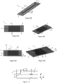
- the device includes a fractionation channel 2.
- a sample 8 comprising particles 12 of different sizes dispersed in a liquid mobile phase 11 can flow from a sample inlet 5 (not shown in figure 2 ) to a sample outlet 6 (not shown in figure 2 ).
- a main component of the flow is in the x direction (transverse to the cross section).
- the device 1 includes a layer 19 being with a microfabricated recess 14 which thickness is less than 100 ⁇ m.
- the recess 14 defines walls of the fractionation channel 2.
- Another wall of the fractionation channel 2 is defined by a semipermeable membrane 10, said membrane being permeable to liquid and being configured to maintain the particles 12 in the fractionation channel 2.
- the device 1 also includes an auxiliary channel 3.
- the auxiliary channel 3 includes an auxiliary outlet 7 (not shown in Figure 2 ).
- the liquid mobile phase 11 can flow through the auxiliary channel 3 from the membrane 10 to the auxiliary outlet 7. Therefore, another component of the flow is in the z relative direction, through the membrane 10.
- the z position of the particles 12 schematically illustrates the particle densities in an established flow: the overall particle 12 density is the highest close to the membrane 10 in the fractionation channel 2. Moreover, the mean particle position of smaller particles 12 is higher relative to the z direction than the mean particle position of the larger particles 12.
- the device 1 includes another layer 19, partially bonded to the layer 19, also being with a microfabricated recess 14, which thickness t is less than 100 ⁇ m, the recess 19 defining walls of the auxiliary channel 3.
- the membrane 10 is mechanically held by encapsulation in between the two layers 19 and then separates the fractionation channel 2 and the auxiliary channel 3: the membrane 10 also defines a wall of the auxiliary channel 3.
- each recess 14 defines the thickness t the corresponding channel (fractionation channel 2 or auxiliary channel 3).
- the recess 14 thickness is less than 100 ⁇ m, preferably in the range from 1 ⁇ m to 100 ⁇ m and preferably in the range from 5 ⁇ m to 50 ⁇ m.
- each recess can be in the range from 1 ⁇ m to 10 cm, preferably 5 ⁇ m to 1 cm and even more preferably from 10 ⁇ m to 500 ⁇ m. This width range combined with a mechanically held membrane 10 by encapsulation in between the two layers makes possible to avoid a frit in the device 1.
- the semipermeable membrane is porous and therefore permeable to a liquid phase.
- the material of the membrane is preferably one of cellulose, mixed cellulose ester, polyvinylidene fluoride (PVDF), polyethersulfone (PES), polycarbonate.
- the size of the pores of the membrane 10 is preferably in the range from 0,010 ⁇ m to 1 ⁇ m. This range of pore size is for instance adapted to stop particles from proteins (of a few kDa) cells (of a few tenth of ⁇ m).
- a membrane 10 may be damaged by a heat treatment over 80 ° C.
- the material of at least one of the layers 19 can be an elastomer. Therefore, it is possible to encapsulate the membrane 10 in between the layers 19, the deformation of at least a layer 19 by the membrane 10, preferably of each of the layers 19, assuring a conformable contact between the layers 19, avoiding possible leaks and/or allowing optimum pressure of the liquid mobile phase 11. Compared to clamping, which requires clamping points on both sides of the channels, encapsulation allows a uniform contact between channels, making possible to increase the channel density while reducing their width and thickness without leaks.
- the deformation of the elastomeric layer(s) 19 also contributes to hold mechanically the membrane 10 by a conformable contact, avoiding the need of a frit to support the membrane, and to risk to mechanically damage the membrane.
- the material of the layer 19 is preferably a thermoplastic elastomer (TPE). Therefore, the layers 19 can be thermobonded and the clamping of the different layers can be avoided.
- TPE thermoplastic elastomer
- the use of a thermoplastic elastomer combined with the thickness t of the recess 14 also makes possible to simplify the fabrication of an asymmetric flow field-flow fractionation device 1 by microfabricating the different layers by molding. Thus, the fabrication process of the asymmetric flow field-flow fractionation device 1 can be faster and cheaper than asymmetric flow field-flow fractionation device of the prior art.
- the bonding between the layers 19 is achieved only by bringing the two layers 19 in contact at a temperature being less than 100°C, preferably in the range from 0°C and 100°C and more preferably in the range from 50°C and 100°C, even more preferably in the range from 75°C and 85°C.
- T g is less than -30°C and even more preferably, T g is less than -50°C.
- the material of a layer 19 can be selected from the group consisting of polystyrène-b-polybutadiène-b-polystyrène (SBS), polystyrène-b-polyisoprène-b-polystyrène (SIS), polystyrène-b-poly(éthylène-butylène)-b-polystyr necessarily (SEBS), polystyrène-b-poly(éthylène-propylène)-b-polystyrène (SEPS), polystyrène-b-poly(éthylène-éthylène/propylène)-b-polystyrène (SEEPS), Flexdym.
- SBS polystyrène-b-polybutadiène-b-polystyrène
- SIS polystyrène-b-polyisoprène-b-polyst
- the recessed layer 19 is unmolded.
- Thermal bonding being due to the interpenetration of the polymers from one layer 19 to the other layer 19, the element formed by both layers 19 is monolithic.
- the imposed contact between the faces 18 lasts preferably for more than 10 min, and more preferably for 30 min. Therefore, the bonding between the layers 19 can resist applied pressures of the liquid mobile phase 11 during the particles separation.
- a manifold can be produced using CNC machining on a hard translucent polymer material (PC, PMMA and/or baked epoxy) or 3D printing.
- the manifold can present standard chromatography female fitting (UNF 1/4-28) or luer taper.
- the conduct can also comprise a stud.
- a stud is for example glued (using Norland Optical Adhesive NOA) or thermally bonded on layer 19 top face portion depending on stud material (PDMS or Flexdym).
- NOA Norland Optical Adhesive NOA
- PDMS thermally bonded on layer 19 top face portion depending on stud material
- PDMS stud material
- a UV beam generated from a UV curing pointer (UTarget from Black Hole Lab) is applied for 30 seconds on the NOA.
- Flexdym thermal bonding at 140°C for 20 s) of the stud on layer 19 is achieved before encapsulating the membrane.
- the 1/16inch tube is held tight in the stud 1mm hole. Tubing is typically used for providing the sample 8 to the conduct or directly to the fractionation channel 2.
- the inner diameter of the tube can be in the range from 50 ⁇ m to 1000 ⁇ m, more preferably from 100 ⁇ m to 250 ⁇ m.
- the asymmetric flow field-flow fractionation device 1 comprises a sample outlet 6.
- the sample outlet 6 connects the fractionation channel 2 to a channel or a conduct.
- the conduct can include a luer connection.
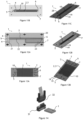
- the asymmetric flow field-flow fractionation device 1 can comprise a serpentine shaped fractionation channel 2.
- the design of the fractionation channel 2 and of the auxiliary channel 3 can be designed to maximize the channels lengths for a determined surface occupied by the fractionation channel 2 and by the auxiliary channel 3 on the chip.
- the serpentine shaped design allows increasing the channel length for a determined surface.
- the length of the fractionation channel 2 and of the auxiliary channel 3 can for example be higher than 1 cm, preferably higher than 5 cm, and even more preferably higher than 10 cm.
- the design of the membrane can be different than the design of the fractionation channel 2 and/or than the design of the auxiliary channel 3.
- the membrane can cover the surface covered by the serpentine shaped channels.
- the membrane 10 is rectangular.
- the device can also include parallel fractionation channels 2 (not shown), i.e. the sample inlet 5 can be fluidically connected to a plurality of fractionation channels 2. Therefore, multiple separations can be performed at the same time, enabling to correct the error made in a single separation measurement.
- the zone 21 can also be a focusing zone 21.
- the asymmetric flow field-flow fractionation device 1 also comprises a separation zone 22, where the fractionation channel 2 and the auxiliary channel 3 are superimposed and separated by the membrane 10.
- the particles 12 are separated by their size in the separation zone 22, as described above.
- the device 1 can comprise a plurality of auxiliary outlets 7.
- the auxiliary channel 3 has a plurality of fluidic branches, at least one of the branches being superimposed under the fractionation channel 2. Therefore, the flowrate of liquid mobile phase 11 flowing out from the device 1 from the auxiliary outlets 7 can be controlled individually, which allows to control different flowrates in different branches of the auxiliary channel 3 which is superimposed under the fractionation channel 2. Therefore, it allows a precise control on the orthogonal force during particles 12 passage in fractionation channel 2. More generally, the portion of the auxiliary channel 3 which is superimposed under the fractionation channel 2 can be split in an integer number n of subportions, allowing an individual control of the flowrate in n distinct subportions.
- the device 1 can be used to fractionate particles 12 from a sample 8, in order to collect new samples comprising particles having a monodispersed size distribution, compared to the size distribution of the particles 12 of the sample 8 injected in the device 1.
- the detection system 26 can be at least one of an absorption spectrometer, for example a UV, a visible absorption spectrometer, a spectrofluorometer, a particle light scattering detector, for example a Multi Angle Light Scattering detector and/or a Dynamic light Scattering detector, a refractometer, for example a differential refractometer, a mass spectrometry system, for example a nano-electrospray ionization mass spectrometry system, a inductively coupled plasma, a liquid chromatography detector and a electrochemical detector.
- an absorption spectrometer for example a UV, a visible absorption spectrometer, a spectrofluorometer, a particle light scattering detector, for example a Multi Angle Light Scattering detector and/or a Dynamic light Scattering detector
- a refractometer for example a differential refractometer
- a mass spectrometry system for example a nano-electrospray
- the system 15 requires preferably a detection system 26 having a low limit of detection, preferably less than 10 ppm, more preferably less than 1 ppm. Therefore, the detection system 26 preferably comprises a nano-electrospray ionization mass spectrometry (MS) system, which detection limit is around 0,1 ppm. Moreover, the nano-electrospray ionization mass spectrometry system is adapted to detect particles in a range of flowrate overlapping the range of flowrate in the fractionation channel 2, for example from 70 ⁇ L/min to 500 ⁇ L/min.
- MS nano-electrospray ionization mass spectrometry
- Another aspect of the invention is a method 130 of size-based particle separation comprising injecting the sample 8 into a device 1.
- the method 130 comprises a step 131, comprising injecting the sample 8 in the sample inlet 5 of the device 1.
- the sample 8 comprises the particles 12 dispersed in the liquid mobile phase 11. The particles are then separated in the fractionation channel 2 of the device 1.
- the method 130 is a method of analyzing the sample 8 composition in particles 12.
- the method 130 can comprise a step 132 of analyzing the sample composition in particles 12.
- analyzing the sample composition in particles 12 can be performed by sequentially detecting the mean quantity of particles 12 flowing through a detection volume in the fractionation microchannel 2 and/or from the outlet of the fractionation microchannel 2.
- the sample outlet 6 can be fluidically connected to a detection system 26.
- the detection system 26 can sequentially detect the mean quantity of particles flowing through a detection volume in a fluidic channel of the particle detector 26. Therefore, the quantities of each size-separated population of particles 12 can be detected as different peaks.
- the detection system 26 can optionally measure the composition of the sample directly by measuring the particles 12 quantity in the fractionation channel 2, i.e. on-chip.
- the method 130 can comprise a step 133 of injecting a liquid mobile phase 11 in the device 1.
- the sample 8 and the liquid mobile phase 11 can be introduced sequentially upstream the sample inlet in a conduct connected to the fractionation channel 2, for example by the sample inlet 5.
- the sample 8 and the liquid mobile phase 11 can also be injected separately to the fractionation channel 2 respectively by the sample inlet 5 and by the mobile phase inlet 4. Therefore, the sequence of sample 8 and mobile phase 11 introduced in the fractionation channel 2 can be controlled by actuating a flowrate controller of sample 8 and a flowrate controller of liquid mobile phase 11.
- the injection flow rate of the liquid mobile phase 11 is preferably in the range from 70 nL/min to 1 mL/min, and preferably in the range from 70 ⁇ L/min to 500 ⁇ L/min.
- Injecting a liquid mobile phase 11 in a step 133 also allows for focusing the sample 8 in the fractionation channel 2.
- the liquid mobile phase 11 is then injected while injecting sample 8 in the device 1, i.e. step 131 and step 132 can be performed in the same time.
- typical junction configuration for focusing can be arranged upstream the fractionation channel 2.
- the liquid mobile phase 11 can be injected in the mobile phase inlet 4, preferably at a flowrate in the range of 70nL/min to 1 mL/min and preferably in the range from 70 ⁇ L/min to 500 ⁇ L/min.
- the liquid mobile phase 11 can permeate into the fractionation channel 2 through the inlet frit 28.
- the liquid mobile phase 11 flow meets the sample 8 flow coming from the sample inlet 5, and compresses the sample toward the membrane 10 wall, achieving hydrodynamic relaxation for 30s, preferably 1s and more preferably 10ms.
Landscapes
- Physics & Mathematics (AREA)
- Health & Medical Sciences (AREA)
- Life Sciences & Earth Sciences (AREA)
- Chemical & Material Sciences (AREA)
- Analytical Chemistry (AREA)
- Biochemistry (AREA)
- General Health & Medical Sciences (AREA)
- General Physics & Mathematics (AREA)
- Immunology (AREA)
- Pathology (AREA)
- Automatic Analysis And Handling Materials Therefor (AREA)
- Other Investigation Or Analysis Of Materials By Electrical Means (AREA)
Claims (16)
- Asymmetrische Flussfeld-Flussfraktionierungsvorrichtung (1), die konfiguriert ist, um in einer flüssigen mobilen Phase (11) dispergierte Teilchen (12) zu trennen, wobei die Vorrichtung Folgendes beinhaltet:• einen Fraktionierungsmikrokanal (2), umfassend einen Probeneinlass (5) und einen Probenauslass (6),• einen Hilfsmikrokanal (3), umfassend einen Hilfsauslass (7),• eine semipermeable Membran (10), die den Fraktionierungsmikrokanal (2) und den Hilfsmikrokanal (3) trennt, wobei die Membran für Flüssigkeit durchlässig ist und konfiguriert ist, um die Teilchen in dem Fraktionierungsmikrokanal zu halten,wobei der Fraktionierungsmikrokanal (2) dem Hilfsmikrokanal (3) überlagert ist, wobei die Vorrichtung (1) zwei Schichten (19) umfasst, dadurch gekennzeichnet, dass die semipermeable Membran (10) von jeder der zwei Schichten (19) verschieden ist, wobei jede Schicht (19) mit einer mikrogefertigten Aussparung (14) ist, deren Stärke weniger als 100 µm ist, die Membran (10) mechanisch durch Verkapselung zwischen den beiden Schichten (19) gehalten wird, wobei die Verkapselung dadurch erlangt wird, dass Flächenabschnitte der zwei Schichten (19) in Kontakt gebracht werden, wobei jeder Flächenabschnitt die Membran umgibt, wobei die Aussparungen jeweils den Fraktionierungsmikrokanal (2) und den Hilfsmikrokanal (3) auf jeder Seite der Membran (10) definieren.
- Vorrichtung (1) nach Anspruch 1, wobei der Fraktionierungsmikrokanal (2) mindestens einen Einlass flüssige mobile Phase (4) umfasst.
- Vorrichtung (1) nach Anspruch 1 oder 2, wobei ein Material mindestens einer Schicht (19), vorzugsweise beider Schichten (19), ein Elastomer ist.
- Vorrichtung (1) nach Anspruch 3, wobei das Material mindestens einer Schicht (19), vorzugsweise beider Schichten (19), ein thermoplastisches Elastomer ist, wobei die Schichten (19) durch Wärme verbunden werden.
- Vorrichtung (1) nach Anspruch 3 oder 4, wobei das Material ein Blockcopolymer mit einer Glasübergangstemperatur Tg umfasst, wobei die Glasübergangstemperatur weniger als 0 °C ist und der Elastizitätsmodul des Materials weniger als 10 MPa ist.
- Vorrichtung (1) nach einem der Ansprüche 3 bis 5, wobei das Material mindestens eines von einem Styrol-Blockcopolymer und einem Ethylen/Butylen-Weichblockcopolymer umfasst.
- Vorrichtung (1) nach einem der Ansprüche 1 bis 6, wobei die Breite des Fraktionierungsmikrokanals (2) von dem Probeneinlass (5) zu dem Probenauslass (6) hin abnimmt.
- Vorrichtung (1) nach einem der Ansprüche 1 bis 6, wobei die Breite des Fraktionierungsmikrokanals (2) von dem Probeneinlass (5) zu dem Probenauslass (6) hin konstant ist.
- System (15), umfassend eine asymmetrische Flussfeld-Flussfraktionierungsvorrichtung (1) nach einem der Ansprüche 1 bis 8 und ein Erfassungssystem (26), wobei der Probenauslass (6) der Vorrichtung (1) fluidisch mit dem Erfassungssystem (26) verbunden ist, wobei das Erfassungssystem mindestens eines von einem Absorptionsspektrometer, einem Spektrofluorometer, einem Mehrwinkel-Lichtstreudetektor, einem Detektor für dynamische Lichtstreuung, einem Refraktometer, einem Nano-Elektrospray-Ionisations-Massenspektrometriesystem und einem induktiv gekoppelten Plasma umfasst.
- System (15) nach Anspruch 9, wobei das Erfassungssystem ein On-Chip-Massenspektrometriesystem und einen durch eine Aussparung in einer Schicht (19) definierten Erfassungskanal umfasst.
- Verfahren (130) zur Abtrennung von Teilchen (12) auf Größenbasis, umfassend ein Injizieren einer Probe (8) in eine asymmetrische Flussfeld-Flussfraktionierungsvorrichtung (1), wobei die Probe (8) die in einer flüssigen mobilen Phase (11) dispergierten Teilchen (12) umfasst und die Vorrichtung (1) Folgendes beinhaltet:• einen Fraktionierungsmikrokanal (2), umfassend einen Probeneinlass (5) und einen Probenauslass (6), wobei die Probe (8) in den Probeneinlass (5) injiziert wird,• einen Hilfsmikrokanal (3), umfassend einen Hilfsauslass (7);• eine semipermeable Membran (10), die den Fraktionierungsmikrokanal (2) und den Hilfsmikrokanal (3) trennt, wobei die Membran für Flüssigkeit durchlässig ist und konfiguriert ist, um die Teilchen in dem Fraktionierungsmikrokanal zu halten,wobei der Fraktionierungsmikrokanal (2) dem Hilfsmikrokanal (3) überlagert ist, wobei die Vorrichtung (1) zwei Schichten (19) umfasst, dadurch gekennzeichnet, dass jede Schicht (19) mit einer mikrogefertigten Aussparung (14) ist, deren Stärke weniger als 100 µm ist, die Membran (10) mechanisch durch Verkapselung zwischen den beiden Schichten (19) gehalten wird, wobei die Verkapselung dadurch erlangt wird, dass Flächenabschnitte der zwei Schichten (19) in Kontakt gebracht werden,wobei die Aussparungen jeweils den Fraktionierungsmikrokanal (2) und den Hilfsmikrokanal (3) auf jeder Seite der Membran (10) definieren.
- Verfahren nach Anspruch 11, wobei der Fraktionierungskanal (2) mindestens einen Einlass für mobile Phase (4) umfasst, das Verfahren umfassend ein Fokussieren der Probe in dem Fraktionierungskanal (2) durch Injizieren der Probe (8) in den Probeneinlass (5), während die flüssige mobile Phase (11) in den Einlass für mobile Phase (4) injiziert wird.
- Verfahren nach Anspruch 11 oder 12, umfassend ein Injizieren der Probe über weniger als 1 Sekunde in den Probeneinlass (5), während die flüssige mobile Phase (11) kontinuierlich injiziert wird.
- Verfahren nach einem der Ansprüche 11 bis 13, das ein Analysieren der Zusammensetzung der Probe (8) in Teilchen (12) durch sequentielles Erfassen der mittleren Menge an Teilchen (12) beinhaltet, die durch ein Erfassungsvolumen in dem Fraktionierungsmikrokanal (2) und/oder aus dem Auslass des Fraktionierungsmikrokanals (2) fließen.
- Verfahren nach einem der Ansprüche 11 bis 14, wobei eine Zusammensetzung der Probe (8) Proteine und Proteinaggregate umfasst, wobei das Verfahren ein Trennen und Analysieren der Zusammensetzung beinhaltet, wobei ein Druck der flüssigen Phase in der Vorrichtung 1 weniger als 8 bar, vorzugsweise weniger als 3 bar, ist
- Verfahren nach einem der Ansprüche 11 bis 15, wobei die Zusammensetzung der Probe (8) entweder Protein-Oligomer-Konjugate oder synthetische Nanopartikel umfasst.
Applications Claiming Priority (2)
| Application Number | Priority Date | Filing Date | Title |
|---|---|---|---|
| EP18305185.3A EP3531125A1 (de) | 2018-02-22 | 2018-02-22 | Mikrofluidische vorrichtung zur asymmetrischen fluss feld-fluss fraktionierung und verfahren zu deren verwendung |
| PCT/EP2019/054365 WO2019162404A1 (en) | 2018-02-22 | 2019-02-21 | Microfluidic asymmetric flow field-flow fractionation device and method of using the same |
Publications (3)
| Publication Number | Publication Date |
|---|---|
| EP3756001A1 EP3756001A1 (de) | 2020-12-30 |
| EP3756001B1 true EP3756001B1 (de) | 2024-07-03 |
| EP3756001C0 EP3756001C0 (de) | 2024-07-03 |
Family
ID=61569188
Family Applications (2)
| Application Number | Title | Priority Date | Filing Date |
|---|---|---|---|
| EP18305185.3A Withdrawn EP3531125A1 (de) | 2018-02-22 | 2018-02-22 | Mikrofluidische vorrichtung zur asymmetrischen fluss feld-fluss fraktionierung und verfahren zu deren verwendung |
| EP19705538.7A Active EP3756001B1 (de) | 2018-02-22 | 2019-02-21 | Mikrofluidische vorrichtung zur asymmetrischen fluss feld-fluss fraktionierung und verfahren zu deren verwendung |
Family Applications Before (1)
| Application Number | Title | Priority Date | Filing Date |
|---|---|---|---|
| EP18305185.3A Withdrawn EP3531125A1 (de) | 2018-02-22 | 2018-02-22 | Mikrofluidische vorrichtung zur asymmetrischen fluss feld-fluss fraktionierung und verfahren zu deren verwendung |
Country Status (3)
| Country | Link |
|---|---|
| US (1) | US11946909B2 (de) |
| EP (2) | EP3531125A1 (de) |
| WO (1) | WO2019162404A1 (de) |
Families Citing this family (2)
| Publication number | Priority date | Publication date | Assignee | Title |
|---|---|---|---|---|
| JP7215366B2 (ja) * | 2019-07-17 | 2023-01-31 | 株式会社島津製作所 | 非対称流流動場分画装置 |
| US20240168018A1 (en) * | 2022-11-18 | 2024-05-23 | Regeneron Pharmaceuticals, Inc. | Methods for detecting and evaluating viruses and virus-like particles |
Family Cites Families (8)
| Publication number | Priority date | Publication date | Assignee | Title |
|---|---|---|---|---|
| WO2002070118A2 (en) * | 2001-02-09 | 2002-09-12 | Microchem Solutions | Apparatus and method for small-volume fluid manipulation and transportation |
| US7495210B2 (en) * | 2006-05-04 | 2009-02-24 | Agilent Technologies, Inc. | Micro fluidic gas assisted ionization device and method |
| US20080108122A1 (en) * | 2006-09-01 | 2008-05-08 | State of Oregon acting by and through the State Board of Higher Education on behalf of Oregon | Microchemical nanofactories |
| US8163182B2 (en) | 2010-05-28 | 2012-04-24 | Wyatt Technology Corporation | Compartmentalized field flow fractionation |
| CA2782675A1 (en) * | 2012-07-05 | 2014-01-05 | Muir Technologies Inc. | Apparatus for detecting a selected liquid contaminant |
| DE102014213428A1 (de) * | 2014-07-10 | 2014-11-27 | Postnova Analytics Gmbh | Vorrichtung für die Feldflussfraktionierung |
| WO2016139042A1 (en) * | 2015-03-05 | 2016-09-09 | Sony Dadc Austria Ag | Microfluidic device and method of manufacture of microfluidic device |
| JP6597221B2 (ja) * | 2015-11-24 | 2019-10-30 | 住友ベークライト株式会社 | 構造体および構造体の製造方法 |
-
2018
- 2018-02-22 EP EP18305185.3A patent/EP3531125A1/de not_active Withdrawn
-
2019
- 2019-02-21 WO PCT/EP2019/054365 patent/WO2019162404A1/en not_active Ceased
- 2019-02-21 US US16/971,763 patent/US11946909B2/en active Active
- 2019-02-21 EP EP19705538.7A patent/EP3756001B1/de active Active
Also Published As
| Publication number | Publication date |
|---|---|
| EP3756001C0 (de) | 2024-07-03 |
| EP3756001A1 (de) | 2020-12-30 |
| WO2019162404A1 (en) | 2019-08-29 |
| EP3531125A1 (de) | 2019-08-28 |
| US11946909B2 (en) | 2024-04-02 |
| US20210088483A1 (en) | 2021-03-25 |
Similar Documents
| Publication | Publication Date | Title |
|---|---|---|
| Smith et al. | Integrated nanoscale deterministic lateral displacement arrays for separation of extracellular vesicles from clinically-relevant volumes of biological samples | |
| Wang et al. | Microfluidics-to-mass spectrometry: a review of coupling methods and applications | |
| Leong et al. | Microfluidic size exclusion chromatography (μSEC) for extracellular vesicles and plasma protein separation | |
| EP1707957B1 (de) | Vorrichtung und System für die Flüssigkeitschromatographie | |
| US6450047B2 (en) | Device for high throughput sample processing, analysis and collection, and methods of use thereof | |
| US7214320B1 (en) | Systems and methods for high throughput sample analysis | |
| EP1688739A1 (de) | Vorrichtungen, Systeme und Verfahren zur Trennung | |
| WO2000016907A1 (en) | Micromachined electrical field-flow fractionation system | |
| US20130260481A1 (en) | Analysis device and analysis method | |
| US11644446B2 (en) | Injecting a liquid borne sample into a field flow fractionator | |
| CN105102113B (zh) | 化学反应器装置 | |
| WO2008020593A1 (en) | Column for chromatography and method for producing the same | |
| US11890580B2 (en) | Field flow fractionator | |
| Song et al. | Free-flow zone electrophoresis of peptides and proteins in PDMS microchip for narrow pI range sample prefractionation coupled with mass spectrometry | |
| Morani et al. | Recent electrokinetic strategies for isolation, enrichment and separation of extracellular vesicles | |
| US11946909B2 (en) | Microfluidic asymmetric flow field-flow fractionation device and method of using the same | |
| Marioli et al. | Continuous asymmetrical flow field-flow fractionation for the purification of proteins and nanoparticles | |
| Shimizu et al. | Femtoliter gradient elution system for liquid chromatography utilizing extended nanofluidics | |
| CN110506201A (zh) | 粒子检测装置和粒子检测方法 | |
| US20180100836A1 (en) | Flow passage unit | |
| US10888860B2 (en) | Sample transfer device and method for sample transfer | |
| WO2013078236A1 (en) | Stopped-flow, micro-fluidic device and method for the charge-based separation of complex analyte mixtures | |
| Zhou et al. | Development of Ultranarrow‐Bore Open Tubular High Efficiency Liquid Chromatography | |
| US20200298236A1 (en) | Fluidic apparatus and method | |
| KR20140032094A (ko) | 표적 물질 포획이 용이한 미세유동 장치 및 상기 미세유동 장치를 이용한 표적 물질 분리 방법 |
Legal Events
| Date | Code | Title | Description |
|---|---|---|---|
| STAA | Information on the status of an ep patent application or granted ep patent |
Free format text: STATUS: UNKNOWN |
|
| STAA | Information on the status of an ep patent application or granted ep patent |
Free format text: STATUS: THE INTERNATIONAL PUBLICATION HAS BEEN MADE |
|
| PUAI | Public reference made under article 153(3) epc to a published international application that has entered the european phase |
Free format text: ORIGINAL CODE: 0009012 |
|
| STAA | Information on the status of an ep patent application or granted ep patent |
Free format text: STATUS: REQUEST FOR EXAMINATION WAS MADE |
|
| 17P | Request for examination filed |
Effective date: 20200922 |
|
| AK | Designated contracting states |
Kind code of ref document: A1 Designated state(s): AL AT BE BG CH CY CZ DE DK EE ES FI FR GB GR HR HU IE IS IT LI LT LU LV MC MK MT NL NO PL PT RO RS SE SI SK SM TR |
|
| AX | Request for extension of the european patent |
Extension state: BA ME |
|
| DAV | Request for validation of the european patent (deleted) | ||
| DAX | Request for extension of the european patent (deleted) | ||
| STAA | Information on the status of an ep patent application or granted ep patent |
Free format text: STATUS: EXAMINATION IS IN PROGRESS |
|
| RAP3 | Party data changed (applicant data changed or rights of an application transferred) |
Owner name: ECOLE NATIONALE SUPERIEURE DE CHIMIE DE PARIS Owner name: UNIVERSITE PARIS CITE Owner name: INSTITUT NATIONAL DE LA SANTE ET DE LA RECHERCHE MEDICALE - INSERM Owner name: CENTRE NATIONAL DE LA RECHERCHE SCIENTIFIQUE -CNRS- Owner name: ASSISTANCE PUBLIQUE, HOPITAUX DE PARIS |
|
| 17Q | First examination report despatched |
Effective date: 20220714 |
|
| GRAP | Despatch of communication of intention to grant a patent |
Free format text: ORIGINAL CODE: EPIDOSNIGR1 |
|
| STAA | Information on the status of an ep patent application or granted ep patent |
Free format text: STATUS: GRANT OF PATENT IS INTENDED |
|
| INTG | Intention to grant announced |
Effective date: 20230814 |
|
| GRAJ | Information related to disapproval of communication of intention to grant by the applicant or resumption of examination proceedings by the epo deleted |
Free format text: ORIGINAL CODE: EPIDOSDIGR1 |
|
| STAA | Information on the status of an ep patent application or granted ep patent |
Free format text: STATUS: EXAMINATION IS IN PROGRESS |
|
| GRAP | Despatch of communication of intention to grant a patent |
Free format text: ORIGINAL CODE: EPIDOSNIGR1 |
|
| INTC | Intention to grant announced (deleted) | ||
| STAA | Information on the status of an ep patent application or granted ep patent |
Free format text: STATUS: GRANT OF PATENT IS INTENDED |
|
| INTG | Intention to grant announced |
Effective date: 20240125 |
|
| RAP3 | Party data changed (applicant data changed or rights of an application transferred) |
Owner name: ECOLE NATIONALE SUPERIEURE DE CHIMIE DE PARIS Owner name: UNIVERSITE DE PARIS Owner name: INSTITUT NATIONAL DE LA SANTE ET DE LA RECHERCHE MEDICALE (INSERM) Owner name: CENTRE NATIONAL DE LA RECHERCHE SCIENTIFIQUE (CNRS) Owner name: ASSISTANCE PUBLIQUE, HOPITAUX DE PARIS |
|
| GRAS | Grant fee paid |
Free format text: ORIGINAL CODE: EPIDOSNIGR3 |
|
| GRAA | (expected) grant |
Free format text: ORIGINAL CODE: 0009210 |
|
| STAA | Information on the status of an ep patent application or granted ep patent |
Free format text: STATUS: THE PATENT HAS BEEN GRANTED |
|
| AK | Designated contracting states |
Kind code of ref document: B1 Designated state(s): AL AT BE BG CH CY CZ DE DK EE ES FI FR GB GR HR HU IE IS IT LI LT LU LV MC MK MT NL NO PL PT RO RS SE SI SK SM TR |
|
| REG | Reference to a national code |
Ref country code: CH Ref legal event code: EP |
|
| REG | Reference to a national code |
Ref country code: DE Ref legal event code: R096 Ref document number: 602019054537 Country of ref document: DE |
|
| U01 | Request for unitary effect filed |
Effective date: 20240726 |
|
| U07 | Unitary effect registered |
Designated state(s): AT BE BG DE DK EE FI FR IT LT LU LV MT NL PT SE SI Effective date: 20240809 |
|
| PG25 | Lapsed in a contracting state [announced via postgrant information from national office to epo] |
Ref country code: NO Free format text: LAPSE BECAUSE OF FAILURE TO SUBMIT A TRANSLATION OF THE DESCRIPTION OR TO PAY THE FEE WITHIN THE PRESCRIBED TIME-LIMIT Effective date: 20241003 |
|
| PG25 | Lapsed in a contracting state [announced via postgrant information from national office to epo] |
Ref country code: GR Free format text: LAPSE BECAUSE OF FAILURE TO SUBMIT A TRANSLATION OF THE DESCRIPTION OR TO PAY THE FEE WITHIN THE PRESCRIBED TIME-LIMIT Effective date: 20241004 Ref country code: PL Free format text: LAPSE BECAUSE OF FAILURE TO SUBMIT A TRANSLATION OF THE DESCRIPTION OR TO PAY THE FEE WITHIN THE PRESCRIBED TIME-LIMIT Effective date: 20240703 |
|
| PG25 | Lapsed in a contracting state [announced via postgrant information from national office to epo] |
Ref country code: IS Free format text: LAPSE BECAUSE OF FAILURE TO SUBMIT A TRANSLATION OF THE DESCRIPTION OR TO PAY THE FEE WITHIN THE PRESCRIBED TIME-LIMIT Effective date: 20241103 |
|
| PG25 | Lapsed in a contracting state [announced via postgrant information from national office to epo] |
Ref country code: CZ Free format text: LAPSE BECAUSE OF FAILURE TO SUBMIT A TRANSLATION OF THE DESCRIPTION OR TO PAY THE FEE WITHIN THE PRESCRIBED TIME-LIMIT Effective date: 20240703 Ref country code: HR Free format text: LAPSE BECAUSE OF FAILURE TO SUBMIT A TRANSLATION OF THE DESCRIPTION OR TO PAY THE FEE WITHIN THE PRESCRIBED TIME-LIMIT Effective date: 20240703 |
|
| PG25 | Lapsed in a contracting state [announced via postgrant information from national office to epo] |
Ref country code: RS Free format text: LAPSE BECAUSE OF FAILURE TO SUBMIT A TRANSLATION OF THE DESCRIPTION OR TO PAY THE FEE WITHIN THE PRESCRIBED TIME-LIMIT Effective date: 20241003 Ref country code: ES Free format text: LAPSE BECAUSE OF FAILURE TO SUBMIT A TRANSLATION OF THE DESCRIPTION OR TO PAY THE FEE WITHIN THE PRESCRIBED TIME-LIMIT Effective date: 20240703 |
|
| PG25 | Lapsed in a contracting state [announced via postgrant information from national office to epo] |
Ref country code: RS Free format text: LAPSE BECAUSE OF FAILURE TO SUBMIT A TRANSLATION OF THE DESCRIPTION OR TO PAY THE FEE WITHIN THE PRESCRIBED TIME-LIMIT Effective date: 20241003 Ref country code: PL Free format text: LAPSE BECAUSE OF FAILURE TO SUBMIT A TRANSLATION OF THE DESCRIPTION OR TO PAY THE FEE WITHIN THE PRESCRIBED TIME-LIMIT Effective date: 20240703 Ref country code: NO Free format text: LAPSE BECAUSE OF FAILURE TO SUBMIT A TRANSLATION OF THE DESCRIPTION OR TO PAY THE FEE WITHIN THE PRESCRIBED TIME-LIMIT Effective date: 20241003 Ref country code: IS Free format text: LAPSE BECAUSE OF FAILURE TO SUBMIT A TRANSLATION OF THE DESCRIPTION OR TO PAY THE FEE WITHIN THE PRESCRIBED TIME-LIMIT Effective date: 20241103 Ref country code: HR Free format text: LAPSE BECAUSE OF FAILURE TO SUBMIT A TRANSLATION OF THE DESCRIPTION OR TO PAY THE FEE WITHIN THE PRESCRIBED TIME-LIMIT Effective date: 20240703 Ref country code: GR Free format text: LAPSE BECAUSE OF FAILURE TO SUBMIT A TRANSLATION OF THE DESCRIPTION OR TO PAY THE FEE WITHIN THE PRESCRIBED TIME-LIMIT Effective date: 20241004 Ref country code: ES Free format text: LAPSE BECAUSE OF FAILURE TO SUBMIT A TRANSLATION OF THE DESCRIPTION OR TO PAY THE FEE WITHIN THE PRESCRIBED TIME-LIMIT Effective date: 20240703 Ref country code: CZ Free format text: LAPSE BECAUSE OF FAILURE TO SUBMIT A TRANSLATION OF THE DESCRIPTION OR TO PAY THE FEE WITHIN THE PRESCRIBED TIME-LIMIT Effective date: 20240703 |
|
| U20 | Renewal fee for the european patent with unitary effect paid |
Year of fee payment: 7 Effective date: 20250129 |
|
| PG25 | Lapsed in a contracting state [announced via postgrant information from national office to epo] |
Ref country code: SM Free format text: LAPSE BECAUSE OF FAILURE TO SUBMIT A TRANSLATION OF THE DESCRIPTION OR TO PAY THE FEE WITHIN THE PRESCRIBED TIME-LIMIT Effective date: 20240703 |
|
| PG25 | Lapsed in a contracting state [announced via postgrant information from national office to epo] |
Ref country code: SK Free format text: LAPSE BECAUSE OF FAILURE TO SUBMIT A TRANSLATION OF THE DESCRIPTION OR TO PAY THE FEE WITHIN THE PRESCRIBED TIME-LIMIT Effective date: 20240703 |
|
| PLBE | No opposition filed within time limit |
Free format text: ORIGINAL CODE: 0009261 |
|
| STAA | Information on the status of an ep patent application or granted ep patent |
Free format text: STATUS: NO OPPOSITION FILED WITHIN TIME LIMIT |
|
| 26N | No opposition filed |
Effective date: 20250404 |
|
| PG25 | Lapsed in a contracting state [announced via postgrant information from national office to epo] |
Ref country code: MC Free format text: LAPSE BECAUSE OF FAILURE TO SUBMIT A TRANSLATION OF THE DESCRIPTION OR TO PAY THE FEE WITHIN THE PRESCRIBED TIME-LIMIT Effective date: 20240703 |
|
| REG | Reference to a national code |
Ref country code: CH Ref legal event code: PL |
|
| PG25 | Lapsed in a contracting state [announced via postgrant information from national office to epo] |
Ref country code: CH Free format text: LAPSE BECAUSE OF NON-PAYMENT OF DUE FEES Effective date: 20250228 |
|
| PG25 | Lapsed in a contracting state [announced via postgrant information from national office to epo] |
Ref country code: IE Free format text: LAPSE BECAUSE OF NON-PAYMENT OF DUE FEES Effective date: 20250221 |
|
| U20 | Renewal fee for the european patent with unitary effect paid |
Year of fee payment: 8 Effective date: 20260121 |
|
| PGFP | Annual fee paid to national office [announced via postgrant information from national office to epo] |
Ref country code: GB Payment date: 20260219 Year of fee payment: 8 |
|
| PG25 | Lapsed in a contracting state [announced via postgrant information from national office to epo] |
Ref country code: RO Free format text: LAPSE BECAUSE OF FAILURE TO SUBMIT A TRANSLATION OF THE DESCRIPTION OR TO PAY THE FEE WITHIN THE PRESCRIBED TIME-LIMIT Effective date: 20240703 |