EP3755954B1 - Cadre pour un dispositif de chauffage electrique comprenant un element deformable elastiquement - Google Patents
Cadre pour un dispositif de chauffage electrique comprenant un element deformable elastiquement Download PDFInfo
- Publication number
- EP3755954B1 EP3755954B1 EP19708354.6A EP19708354A EP3755954B1 EP 3755954 B1 EP3755954 B1 EP 3755954B1 EP 19708354 A EP19708354 A EP 19708354A EP 3755954 B1 EP3755954 B1 EP 3755954B1
- Authority
- EP
- European Patent Office
- Prior art keywords
- heating
- housing
- longitudinal
- frame
- displacement reducing
- Prior art date
- Legal status (The legal status is an assumption and is not a legal conclusion. Google has not performed a legal analysis and makes no representation as to the accuracy of the status listed.)
- Active
Links
Images
Classifications
-
- F—MECHANICAL ENGINEERING; LIGHTING; HEATING; WEAPONS; BLASTING
- F24—HEATING; RANGES; VENTILATING
- F24H—FLUID HEATERS, e.g. WATER OR AIR HEATERS, HAVING HEAT-GENERATING MEANS, e.g. HEAT PUMPS, IN GENERAL
- F24H3/00—Air heaters
- F24H3/02—Air heaters with forced circulation
- F24H3/04—Air heaters with forced circulation the air being in direct contact with the heating medium, e.g. electric heating element
- F24H3/0405—Air heaters with forced circulation the air being in direct contact with the heating medium, e.g. electric heating element using electric energy supply, e.g. the heating medium being a resistive element; Heating by direct contact, i.e. with resistive elements, electrodes and fins being bonded together without additional element in-between
- F24H3/0429—For vehicles
- F24H3/0452—Frame constructions
- F24H3/0458—One-piece frames
-
- F—MECHANICAL ENGINEERING; LIGHTING; HEATING; WEAPONS; BLASTING
- F24—HEATING; RANGES; VENTILATING
- F24H—FLUID HEATERS, e.g. WATER OR AIR HEATERS, HAVING HEAT-GENERATING MEANS, e.g. HEAT PUMPS, IN GENERAL
- F24H3/00—Air heaters
- F24H3/02—Air heaters with forced circulation
- F24H3/04—Air heaters with forced circulation the air being in direct contact with the heating medium, e.g. electric heating element
- F24H3/0405—Air heaters with forced circulation the air being in direct contact with the heating medium, e.g. electric heating element using electric energy supply, e.g. the heating medium being a resistive element; Heating by direct contact, i.e. with resistive elements, electrodes and fins being bonded together without additional element in-between
- F24H3/0429—For vehicles
-
- B—PERFORMING OPERATIONS; TRANSPORTING
- B60—VEHICLES IN GENERAL
- B60H—ARRANGEMENTS OF HEATING, COOLING, VENTILATING OR OTHER AIR-TREATING DEVICES SPECIALLY ADAPTED FOR PASSENGER OR GOODS SPACES OF VEHICLES
- B60H1/00—Heating, cooling or ventilating devices
- B60H1/22—Heating, cooling or ventilating devices the heat source being other than the propulsion plant
- B60H1/2215—Heating, cooling or ventilating devices the heat source being other than the propulsion plant the heat being derived from electric heaters
- B60H1/2225—Heating, cooling or ventilating devices the heat source being other than the propulsion plant the heat being derived from electric heaters arrangements of electric heaters for heating air
-
- F—MECHANICAL ENGINEERING; LIGHTING; HEATING; WEAPONS; BLASTING
- F24—HEATING; RANGES; VENTILATING
- F24H—FLUID HEATERS, e.g. WATER OR AIR HEATERS, HAVING HEAT-GENERATING MEANS, e.g. HEAT PUMPS, IN GENERAL
- F24H3/00—Air heaters
- F24H3/02—Air heaters with forced circulation
- F24H3/04—Air heaters with forced circulation the air being in direct contact with the heating medium, e.g. electric heating element
- F24H3/0405—Air heaters with forced circulation the air being in direct contact with the heating medium, e.g. electric heating element using electric energy supply, e.g. the heating medium being a resistive element; Heating by direct contact, i.e. with resistive elements, electrodes and fins being bonded together without additional element in-between
- F24H3/0429—For vehicles
- F24H3/0452—Frame constructions
- F24H3/0476—Means for putting the electric heaters in the frame under strain, e.g. with springs
-
- H—ELECTRICITY
- H05—ELECTRIC TECHNIQUES NOT OTHERWISE PROVIDED FOR
- H05B—ELECTRIC HEATING; ELECTRIC LIGHT SOURCES NOT OTHERWISE PROVIDED FOR; CIRCUIT ARRANGEMENTS FOR ELECTRIC LIGHT SOURCES, IN GENERAL
- H05B3/00—Ohmic-resistance heating
- H05B3/20—Heating elements having extended surface area substantially in a two-dimensional [2D] plane, e.g. plate-heater
- H05B3/22—Heating elements having extended surface area substantially in a two-dimensional [2D] plane, e.g. plate-heater non-flexible
- H05B3/24—Heating elements having extended surface area substantially in a two-dimensional [2D] plane, e.g. plate-heater non-flexible heating conductor being self-supporting
-
- B—PERFORMING OPERATIONS; TRANSPORTING
- B60—VEHICLES IN GENERAL
- B60H—ARRANGEMENTS OF HEATING, COOLING, VENTILATING OR OTHER AIR-TREATING DEVICES SPECIALLY ADAPTED FOR PASSENGER OR GOODS SPACES OF VEHICLES
- B60H1/00—Heating, cooling or ventilating devices
- B60H1/22—Heating, cooling or ventilating devices the heat source being other than the propulsion plant
- B60H2001/2268—Constructional features
- B60H2001/2278—Connectors, water supply, housing, mounting brackets
-
- F—MECHANICAL ENGINEERING; LIGHTING; HEATING; WEAPONS; BLASTING
- F24—HEATING; RANGES; VENTILATING
- F24H—FLUID HEATERS, e.g. WATER OR AIR HEATERS, HAVING HEAT-GENERATING MEANS, e.g. HEAT PUMPS, IN GENERAL
- F24H9/00—Details
- F24H9/18—Arrangement or mounting of grates or heating means
- F24H9/1854—Arrangement or mounting of grates or heating means for air heaters
- F24H9/1863—Arrangement or mounting of electric heating means
- F24H9/1872—PTC resistor
-
- H—ELECTRICITY
- H05—ELECTRIC TECHNIQUES NOT OTHERWISE PROVIDED FOR
- H05B—ELECTRIC HEATING; ELECTRIC LIGHT SOURCES NOT OTHERWISE PROVIDED FOR; CIRCUIT ARRANGEMENTS FOR ELECTRIC LIGHT SOURCES, IN GENERAL
- H05B2203/00—Aspects relating to Ohmic resistive heating covered by group H05B3/00
- H05B2203/02—Heaters using heating elements having a positive temperature coefficient
-
- H—ELECTRICITY
- H05—ELECTRIC TECHNIQUES NOT OTHERWISE PROVIDED FOR
- H05B—ELECTRIC HEATING; ELECTRIC LIGHT SOURCES NOT OTHERWISE PROVIDED FOR; CIRCUIT ARRANGEMENTS FOR ELECTRIC LIGHT SOURCES, IN GENERAL
- H05B2203/00—Aspects relating to Ohmic resistive heating covered by group H05B3/00
- H05B2203/022—Heaters specially adapted for heating gaseous material
- H05B2203/023—Heaters of the type used for electrically heating the air blown in a vehicle compartment by the vehicle heating system
Definitions
- the invention relates to electric heating devices, in particular for a ventilation, heating and/or air conditioning installation of a motor vehicle.
- Heating the air intended for heating the passenger compartment of a motor vehicle, as well as for demisting and defrosting the glass surfaces, is ensured by heat exchange between an air flow and an engine coolant. circulating in a heat exchanger.
- Such an electric heating device generally comprises a frame having a heating body comprising a plurality of parallel conductive plates between which resistive heating elements are mounted, for example resistors with a positive temperature coefficient (PTC), and radiant elements increasing the heat exchange surface with the air flow passing through the heating device.
- PTC positive temperature coefficient
- the housing defined by walls, comprises elastic elements formed of tongues inclined relative to the walls from which they are articulated, so as to be arranged in the housing and the insertion path during assembly of the 'heating element.
- These elastic tabs are thus constrained during insertion of the or heating elements and they then exert an elastic restoring force participating in pressing the corresponding heating element towards the opposite wall of the housing.
- the invention aims to propose an alternative to the known frameworks of additional electric heating devices, which is at least as efficient and reliable.
- the invention proposes a frame for a device for electrically heating a flow of air circulating inside a ventilation, heating and/or air conditioning installation of a motor vehicle according to claim 1.
- a frame comprises at least one housing intended to receive at least one heating element, the housing being delimited by a plurality of longitudinal walls forming a longitudinal insertion path for a heating element.
- the insertion path is delimited longitudinally by a bottom wall which extends opposite an opening through which the heating element intended to come into the housing can be inserted, a direction of insertion being defined from the opening up to the back wall.
- At least one of the longitudinal walls of the housing comprises a travel reduction element projecting from said wall, said travel reduction element being configured to come into contact with said at least one heating element and comprising a ramp extending progressively towards the interior of the housing relative to the direction of insertion, approaching the opposite longitudinal wall, said travel reduction element being arranged so that its downstream end extends at a distance from the bottom wall .
- the invention offers an alternative for maintaining heating elements in a heating device.
- a travel reduction element comprising a ramp makes it possible to maintain the heating element in the housing by compensating for the existing clearance between the heating element and the housing whatever the dimension of the clearance, without requiring excessive insertion efforts.
- the travel reduction element according to the invention is configured to come into contact with the heating element.
- the fact that the downstream end extends at a distance from the bottom wall offers flexibility at this contact zone which again makes it possible to reduce the insertion forces to be provided and to avoid deformation of the heating element when it comes into contact with the travel reduction element.
- the performance of the heating elements is not impaired.
- the ramp shape of the travel reduction element makes it possible to gradually guide, during its insertion, the heating element towards the opposite longitudinal wall.
- This form of ramp extends from the upstream end of the travel reduction element, that is to say the end to be covered first by the heating element during its insertion, which is located in the plane of the longitudinal wall.
- the downstream end, at a distance from the bottom wall, can correspond to the top of the travel reduction element, that is to say the point most inside the housing.
- downstream face of the travel reduction element that is to say a face connecting the top of this element to the longitudinal wall, in the direction of the bottom wall, is substantially perpendicular to the wall longitudinal and parallel to the bottom wall.
- the invention also relates to an electric heating device comprising at least one heating element characterized in that it comprises a frame as described above and in which the at least one heating element is arranged.
- Said at least one heating element can be pushed into contact with the travel reduction element, in the direction of the wall opposite the longitudinal wall on which the travel reduction element is located.
- the longitudinal axis L corresponds to the direction of elongation of the frame of the electric heating device
- the transverse axis T perpendicular to the longitudinal axis L corresponds to the direction followed by the flow of air to be heated passing through the heating device.
- heating and the vertical axis V is perpendicular to both the longitudinal axis L and the transverse axis T. It should be noted that the choice of the names of these axes does not limit the orientation that can take the electric heating device in its application to a motor vehicle.
- the electric heating device 1 shown in figure 1 is intended to be housed in an air circulation duct of a ventilation, heating and/or air conditioning installation, so as to transform the electrical energy taken from the vehicle into thermal energy returned to the air passing through this led.
- the installation is not shown here, but it will be understood that a main conduit of this installation conventionally comprises an opening made in the wall for the insertion of the electric heating device 1.
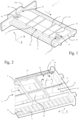
- FIG. 1 shows an electric heating device 1 according to the invention, comprising a frame 3 in which heating elements 5, capable of transforming an electric current into thermal energy, have been inserted.
- the frame 3 includes travel reduction elements 10 which will be described later.
- the heating elements 5 comprise means capable of exchanging heat, such as radiant elements 53 making it possible to increase the heat exchange surface, with the air flow passing through the electric heating device 1.
- the heating elements 5 comprise also electrodes 54 between which resistive heating elements are arranged, for example resistors with a positive temperature coefficient (PTC), and against which the radiant elements 53 are fixed.
- PTC positive temperature coefficient
- the electrodes 54 and the PTC resistors make it possible to transform an electric current into thermal energy. It should be noted that the resistors with a positive temperature coefficient can be glued directly to the radiant elements 53.
- the frame 3 comprises a heating compartment 30, forming a receiving casing for the heating elements 5, and a connection interface 100 provided at one of its ends.
- the heating elements 5 are inserted into housings 7 (references visible on the figures 3 and 4 ) provided inside the heating compartment 30.
- the connection interface 100 closes an opening 50 through which the heating elements 5 are inserted into the housings 7 of the heating compartment 30, at the same time as it allows the connection from the electric heating device 1 to an electrical network of the vehicle allowing the electrical supply of the heating elements 5.
- the frame 3 and the heating compartment 30 have the shape of a rectangular parallelepiped.
- the two main faces of the frame 3, respectively front and rear, opposite along the transverse axis T, are perforated to allow the passage of an air flow and a diffusion of heat in the conduit where the electric heating device 1 is installed.
- the frame 3 comprises a median plane corresponding to a plane passing through one half of the frame and being perpendicular to a direction followed by the flow of air circulating through the electric heating device 1. It is understood that the front and rear faces of the frame 3 extend in planes parallel to the median plane.
- the frame 3 comprises bars 9 arranged, here, on the periphery of the heating compartment 30. These bars 9 contribute to the stiffening of the frame 3 and include ventilation slots 90 allowing the air flow to circulate at across.
- the ventilation slots 90 are positioned one after the other along the longitudinal axis L of the heating device 1, it being understood that the shape and number of the air passages here formed by the slots is not limiting. of the invention. It results from the arrangement on the periphery of the strips 9 that the housings 7 are attached to each other.
- the heating compartment 30 comprises a plurality of walls. Among these walls, there are longitudinal walls 23, 25 extending along the longitudinal axis L with two lateral longitudinal walls 23 and at least one intermediate longitudinal wall 25. The lateral longitudinal walls 23 delimit between them a vertical dimension of the storage compartment. heater 30, and the intermediate longitudinal walls 25 extend parallel to the side longitudinal walls 23 and inside the heating compartment 30, so as to define, between them and with the side longitudinal walls 23, several housings 7 at the interior of the heating compartment 30.
- each housing 7 of the frame 3 is delimited by walls. More precisely, each housing 7 is delimited vertically by two longitudinal walls 23, 25, which can be lateral 23 or intermediate 25.
- the frame 3 comprises two housings 7 with an intermediate longitudinal wall 25.
- a side longitudinal wall 23 and the longitudinal wall intermediate 25 delimit, between them and vertically, an insertion path for the heating element 5.
- the insertion path corresponds to the path taken by the heating element 5 during its insertion inside the frame.
- the spacing between the longitudinal walls 23, 25 of the same housing 7 corresponds to the vertical dimension of the heating element 5, within manufacturing clearances.
- Each housing 7 is further delimited by a bottom wall 21 extending in a vertical transverse plane. This bottom wall 21 is located opposite the opening through which the heating elements 5 are inserted into the heating compartment 30. It should be noted that, according to the illustrated embodiment, the heating elements 5 are inserted in the housings 7 following a direction of insertion parallel to the longitudinal axis L. The direction of insertion S is defined from the opening towards the bottom wall 21.
- the frame 3 also includes ribs 6 transversely delimiting the path of insertion of the heating element 5 into the housing.
- the ribs 6 extend at least between two longitudinal walls 23, 25 forming the same housing 7, and it should be noted that these ribs also have a role of stiffening the frame 3 and the heating compartment 30. spacing between two ribs 6 located on either side of the insertion path along the transverse axis T corresponds to the transverse dimension of the heating element 5, within manufacturing clearances.
- the frame 3, and more particularly at least one longitudinal wall 23, 25 participating in defining a housing receiving a heating element comprises at least one travel reduction element 10 mentioned above.
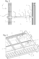
- FIG. 2 illustrates the frame without the heating elements, to make visible two travel reduction elements 10 respectively arranged in a housing 7, across the insertion path of the heating element brought to occupy this housing, each travel reduction element being configured so as to have a downstream end at a distance from the bottom wall 21.
- Each travel reduction element 10 extends projecting from a longitudinal wall 23, 25 and it comprises an inclined surface 11 forming a ramp which extends progressively towards the inside of the housing 7, approaching the opposite longitudinal wall. More particularly, the travel reduction element 10 has, in longitudinal section, that is to say in a longitudinal and vertical section plane, a triangular shape.
- the inclined surface 11 extends from an upstream end 12 of the travel reduction element, away from the corresponding longitudinal wall, and towards the opposite longitudinal wall. More precisely, the inclined surface 11 forms an angle ⁇ with the longitudinal wall 23, 25 from which the travel reduction element projects.
- the ramp formed by this inclined surface extends in the extension of the longitudinal wall and it extends to an end edge forming a vertex edge 13, this end edge being the part of the reduction element of travel furthest inside the housing and therefore the part likely to be in contact with the heating element whatever the manufacturing clearances.
- the ramp extends regularly and continuously from the upstream end 12 to the top edge 13, so that the force of insertion of the heating element remains measured, without any shock that could form an element without a ramp.
- the inclined surface will form an obstacle to the insertion of the heating element at the level of its upstream end or at the level of the summit ridge.
- the presence of this travel reduction element tends to deflect the heating element towards the opposite longitudinal wall, and to freeze the heating element in position in the frame, so as to reduce the beating of the components when the heating device is assembled. More particularly, and as shown schematically on the figure 1 , the edges of the radiant elements 53 brought to be arranged facing this longitudinal wall opposite to that carrying the travel reduction element can be slightly crushed against the longitudinal wall, which helps to freeze the position of the heating element.
- the travel reduction element further comprises a downstream face 14, which connects the top edge 13 to the longitudinal wall, downstream of the top edge, that is to say opposite the inclined surface 11 forming a ramp.
- this downstream face 14 is straight, arranged in a vertical and transverse plane also including the summit edge. In this way, the downstream face is perpendicular to the longitudinal wall and parallel to the bottom wall. It is understood that in a variant not shown, the downstream face could be inclined and have a vertical dimension gradually decreasing until the junction of the downstream end 15 with the longitudinal wall, since this junction with the wall longitudinal extends at a distance from the bottom wall in accordance with the characteristic of the invention previously described.
- the travel reduction element not engage with the bottom wall 21, which forms a surface for stopping the translation of the heating element, perpendicular to its insertion in the accommodation.
- the fact that the junction of the downstream end 15 of the travel reduction element with one of the walls defining the housing is independent of the bottom wall allows flexibility of the travel reduction element in its zone of contact with the heating element and in particular at the level of the top edge 13, which can sag slightly under the insertion force towards the bottom wall 21 and therefore, if necessary, reduce this force a little. insertion to be provided, while correctly ensuring the function of reducing travel without taking the risk of this element breaking due to its mass nature.
- the movement of the heating elements 5 inside the housings can be greater at their longitudinal ends close to the bottom wall, it is preferable that the travel reduction elements are located in the vicinity of the bottom wall, and in particular in a zone defined between the bottom wall 21 and a central part of the housing 7 relative to its longitudinal dimension.
- the travel reduction element is in a zone close to the bottom wall, and in any case in the second longitudinal part of the frame, that is to say, relative to this longitudinal dimension, between a central part of the housing and the back wall. It can be provided that the downstream end of the travel reduction element, namely the downstream face 14 or the junction of this downstream face with the longitudinal wall in the case where the downstream face is not parallel to the wall of bottom 21, is arranged at a longitudinal distance from the bottom wall of between 10 and 30 millimeters.
- downstream end is sufficiently far from the bottom wall to provide, if necessary, a certain flexibility to the travel reduction element, particularly at the level of its top edge 13, while remaining in a context of reduction of travel at the end of the heating element insertion stroke, that is to say in the area where the heating element is most likely to debate.
- the travel reduction element 10 can have a length, measured along the longitudinal axis L, which can for example be between 10 and 15mm.
- the width of a travel reduction element may be different from the width of the travel reduction element shown on the figure 2 .
- the travel reduction element may have a width equal to half the width of the longitudinal wall from which it extends, being centered transversely on the latter.
- the height of a travel reduction element can be of the order of 1 to 10% of the height of the housing in which it extends.
- the height of the travel reduction element, measured along the vertical axis V is between 0.5 and 1.5 millimeters and more particularly between 1 and 1.5 millimeters, knowing that the manufacturing clearance between the heating element 5 and the housing 7 is generally between 0.2 millimeter and 0.5 millimeter.
- the travel reduction element differs from the above in that the inclined surface 11 forming the guide ramp for the heating element has bearings 16, here three in number. These bearings regularly interrupt the slope of the ramp and thus provide interruptions in the increase in the effort of inserting the heating elements into the housing. It will be understood that the number of bearings could be different from that illustrated here, without departing from the context of this alternative embodiment of the invention.
- FIG. 4 illustrates a second embodiment of the invention, which is distinguished in particular by the configuration of the upstream face forming a ramp.
- This inclined surface 11 here has a triangular shape having the consequence of forming a projecting edge 17 oriented towards the housing 7.
- the projecting edge 17 is intended to come into contact with the heating element 5. Such an edge makes it possible to generate a deformation plastic of the heating element, drilling it if necessary.
- the projecting edge 17 preferably extends along the direction of insertion S of the heating element into the housing. Thus, here the projecting edge 17 extends along the axis of longitudinal elongation of the longitudinal wall 23, 25 on which the travel reduction element 10 is located.
- the travel reduction element has an inclined surface 11 forming an angle ⁇ with the longitudinal wall 23, 25 on which it is located, and this travel reduction element is configured so as to extend at a distance of the bottom wall, with a downstream end engaging the longitudinal wall.
- the travel reduction element 10 can be formed by an attached part, that is to say a part produced separately then made integral with the corresponding longitudinal wall, or well it can be made integral with the longitudinal wall 23, 25 of the housing 7, in particular by a single molding operation.
- the heating elements 5 are first inserted into the appropriate housings 7 inside the heating compartment 30. To do this, the heating elements 5 are inserted through the opening formed at one end of the frame 3, and the heating elements 5 are slid in translation towards the bottom wall 21 of the housing 7, in particular in the direction of insertion shown by the arrow S.
- the heating element 5 comes into contact with the travel reduction element arranged across the insertion path. This heating element 5 is then deviated from its initial rectilinear trajectory, being pushed by the travel reduction element towards the longitudinal wall opposite to that on which the travel reduction element is provided. deflection.
- the fact that the travel reduction element has a free downstream end, that is to say an end which extends longitudinally at a distance from the bottom wall, generates a flexibility which allows a slight deformation of the travel element. reduction of clearance at the edge in contact with the heating element. In this way, the efforts required to push the heating element to the bottom wall, while it is otherwise pushed against a longitudinal wall via the travel reduction element, are minimal.
- the insertion of the heating element 5 continues until it meets the bottom wall 21 or another mechanical stop of the heating device.
- connection interface 100 is then arranged at one end of the heating compartment 30 and allows the connection of the electric heating device 1 to an electrical network of the vehicle .
- the heating device 1 is then inserted into a conduit of the heating, ventilation and/or air conditioning installation.
- these travel reduction elements are optimized on the one hand by their ramp shape so that they allow a deflection of the heating elements during their insertion, by providing sufficient rigidity to achieve this deviation and/or deformation and to avoid the risk of breakage when handling the heating device, and on the other hand by their downstream end configured not to extend until the bottom wall, which allows flexibility of the travel reduction element making it possible to limit the effect of contact of the travel reduction element on the corresponding heating element.
- the travel reduction element according to the invention is not a deformable element caused to return to its original position by return effort, but rather a fixed element whose position within the housing does not is not modified by the passage of the heating element, with where appropriate a flexibility generated locally at the edge edge formed at the end of the ramp to allow the passage of this heating element.
Landscapes
- Engineering & Computer Science (AREA)
- Physics & Mathematics (AREA)
- Thermal Sciences (AREA)
- Mechanical Engineering (AREA)
- Chemical & Material Sciences (AREA)
- Combustion & Propulsion (AREA)
- General Engineering & Computer Science (AREA)
- Air-Conditioning For Vehicles (AREA)
- Resistance Heating (AREA)
- Central Heating Systems (AREA)
Description
- L'invention concerne les dispositifs de chauffage électrique, notamment pour une installation de ventilation, de chauffage et/ou de climatisation d'un véhicule automobile.
- Le réchauffage de l'air destiné au chauffage de l'habitacle d'un véhicule automobile, ainsi qu'au désembuage et au dégivrage des surfaces vitrées, est assuré par échange de chaleur entre un flux d'air et un liquide de refroidissement du moteur circulant dans un échangeur de chaleur.
- Au démarrage du moteur et pendant une certaine durée suivant le temps de démarrage, les calories transportées par le liquide de refroidissement du moteur sont insuffisantes pour assurer un chauffage rapide et efficace de l'air amené à être soufflé dans l'habitacle. Cela est observé plus particulièrement avec certains types de moteur et présente un inconvénient par temps froid, car non seulement la température interne de l'habitacle ne peut être élevée rapidement, mais en outre les fonctions de désembuage et de dégivrage ne peuvent être assurées efficacement.
- Pour remédier à ces inconvénients, il a été proposé de monter un dispositif de chauffage électrique additionnel dans le flux d'air dirigé vers l'habitacle, comme par exemple dans le document
FR 2954 469 A1 - Un tel dispositif de chauffage électrique comprend généralement un cadre présentant un corps de chauffe comprenant une pluralité de plaques conductrices parallèles entre lesquelles sont montés des éléments résistifs chauffants, par exemple des résistances à coefficient de température positif (CTP), et des éléments radiants augmentant la surface d'échange thermique avec le flux d'air traversant le dispositif de chauffage.
- Ces différents éléments sont assemblés de manière à former au moins un élément chauffant, le ou les éléments chauffants constitutifs du corps de chauffe étant alors insérés dans un logement de celui-ci. À cet effet, le logement, défini par des parois, comporte des éléments élastiques formés de languettes inclinées par rapport aux parois à partir desquelles elles sont articulées, de manière à être disposé dans le logement et le chemin d'insertion lors du montage de l'élément chauffant. Ces languettes élastiques sont ainsi contraintes lors de l'insertion du ou des éléments chauffants et elles exercent alors une force de rappel élastique participant au plaquage de l'élément chauffant correspondant vers la paroi opposée du logement. On s'assure ainsi de la réduction de débattement de l'élément chauffant dans son logement qui doit être prévu avec des dimensions sensiblement supérieures à celles de l'élément chauffant pour permettre son insertion.
- L'inconvénient lié à l'utilisation de ces éléments élastiques exerçant une force de rappel sur les éléments chauffants réside dans le fait que durant le roulage, ou en cas de chute du dispositif de chauffage, les éléments élastiques sont soumis à des vibrations plus ou moins importantes. Ces vibrations peuvent occasionner un bruit dans le circuit de ventilation desservant l'habitacle pouvant occasionner une gêne pour les usagers du véhicule automobile. Il est également possible que ces vibrations fragilisent voire cassent les éléments élastiques, les éléments chauffants n'étant alors plus maintenus correctement dans leur logement, ce qui peut provoquer au moins, là encore, une gêne sonore pour les usagers ou contribuer à une rupture mécanique des éléments chauffants.
- Dans ce contexte, l'invention vise à proposer une alternative aux cadres connus de dispositifs de chauffage électrique additionnels, qui soit au moins aussi efficace, fiable.
- L'invention propose à cet effet un cadre pour un dispositif de chauffage électrique d'un flux d'air circulant à l'intérieur d'une installation de ventilation, de chauffage, et/ou de climatisation d'un véhicule automobile selon la revendication 1. Un tel cadre comprend au moins un logement destiné à recevoir au moins un élément chauffant, le logement étant délimité par une pluralité de parois longitudinales formant un chemin d'insertion longitudinal pour un élément chauffant. Le chemin d'insertion est délimité longitudinalement par une paroi de fond qui s'étend à l'opposé d'une ouverture par laquelle peut être inséré l'élément chauffant destiné à venir dans le logement, un sens d'insertion étant défini depuis l'ouverture jusqu'à la paroi de fond. Selon l'invention, au moins l'une des parois longitudinales du logement comprend un élément de réduction de débattement faisant saillie de ladite paroi, ledit élément de réduction de débattement étant configuré pour venir au contact dudit au moins un élément chauffant et comportant une rampe s'étendant progressivement vers l'intérieur du logement par rapport au sens d'insertion, en rapprochement de la paroi longitudinale opposée, ledit élément de réduction de débattement étant agencé de sorte que son extrémité aval s'étend à distance de la paroi de fond.
- Ainsi, l'invention offre une alternative pour le maintien des éléments chauffants dans un dispositif de chauffage. La présence d'un élément de réduction de débattement comportant une rampe permet de maintenir l'élément chauffant dans le logement en compensant le jeu existant entre l'élément chauffant et le logement quelle que soit la dimension du jeu, sans nécessiter des efforts d'insertion trop importants. Par compenser le jeu, on entend que l'élément de réduction de débattement selon l'invention est configuré pour venir au contact de l'élément chauffant. Le fait que l'extrémité aval s'étende à distance de la paroi de fond offre une flexibilité au niveau de cette zone de contact ce qui permet là encore de diminuer les efforts d'insertion à fournir et d'éviter une déformation de l'élément chauffant lorsque celui-ci vient au contact de l'élément de réduction de débattement. Ainsi, les performances des éléments chauffants ne sont pas altérées.
- La forme de rampe de l'élément de réduction de débattement permet de guider progressivement, lors de son insertion, l'élément chauffant en direction de la paroi longitudinale opposée. Cette forme de rampe s'étend depuis l'extrémité amont de l'élément de réduction du débattement, c'est-à-dire l'extrémité amenée à être recouverte en premier par l'élément chauffant lors de son insertion, qui se trouve dans le plan de la paroi longitudinale. L'extrémité aval, à distance de la paroi de fond, peut correspondre au sommet de l'élément de réduction de débattement, c'est-à-dire le point le plus à l'intérieur du logement.
- On peut prévoir que la face aval de l'élément de réduction de débattement, c'est-à-dire une face reliant le sommet de cet élément à la paroi longitudinale, en direction de la paroi de fond, est sensiblement perpendiculaire à la paroi longitudinale et parallèle à la paroi de fond.
- Selon une ou plusieurs caractéristiques pouvant être prise seule ou en en combinaison, on pourra prévoir que :
- L'élément de réduction de débattement est situé sur un plan médian du cadre, et donc du logement dans lequel il s'étend. Ainsi, on s'assure, quelle que soit la largeur de l'élément de réduction de débattement, que la position de l'élément chauffant dans le logement est équilibrée.
- La paroi longitudinale comprend plusieurs éléments de réduction de débattement. De la sorte, l'élément chauffant peut être au contact de tels éléments sur plusieurs endroits et sa position dans le logement peut être d'autant plus stable.
- Les parois longitudinales définissant le logement comprennent chacune au moins un élément de réduction de débattement.
- Les éléments de réduction de débattement sont disposés en alternance sur une première paroi longitudinale et sur une deuxième paroi longitudinale. Par « en alternance », on entend par exemple que les éléments de réduction de débattement de la première paroi longitudinale ne partagent pas les axes transversaux des éléments de réduction de débattement situés sur la deuxième paroi longitudinale. Le décalage peut être constant. Il est entendu que cette caractéristique est également applicable dans le cas où il n'y aurait qu'un seul élément de réduction de débattement sur chacune des parois longitudinales.
- L'élément de réduction de débattement comporte une surface inclinée formant rampe, ladite surface inclinée présentant un angle d'inclinaison par rapport à la paroi longitudinale sur laquelle l'élément de réduction de débattement est situé.
- L'élément de réduction de débattement présente au moins une arête saillante agencée dans le prolongement de la surface inclinée et qui forme le sommet de l'élément de réduction de débattement, cette arête de sommet étant la partie de l'élément de réduction de débattement la plus à l'intérieur du logement. De la sorte, cette arête est une partie de l'élément de réduction de débattement susceptible d'être toujours au contact de l'élément chauffant lors de l'insertion de celui-ci, quels que soient les jeux de fabrication du cadre et de l'élément chauffant.
- L'extrémité aval de l'élément de réduction de débattement présente une face aval sensiblement parallèle à la paroi de fond. Un bord de cette face aval, à l'opposé de la paroi longitudinale qu'elle rejoint, forme l'arête saillante à sa jonction avec la surface inclinée formant rampe.
- L'élément de réduction de débattement est dans une zone définie entre la paroi de fond et une partie centrale du logement relativement à sa dimension longitudinale. On pourra prévoir que l'extrémité aval de l'élément de réduction de débattement est agencée à une distance longitudinale de la paroi de fond comprise entre 10 et 30 millimètres. De la sorte, l'extrémité aval est suffisamment loin de la paroi de fond pour autoriser le cas échéant une déformation de la partie de l'élément de réduction de débattement au contact de l'élément chauffant, tout en restant dans un contexte de réduction de débattement en fin de course d'insertion de l'élément chauffant, c'est-à-dire dans la zone où l'élément chauffant est le plus à même de débattre.
- L'élément de réduction de débattement est venu de matière avec la paroi longitudinale sur laquelle l'élément de réduction de débattement est situé. Une telle configuration permet de faciliter les opérations de fabrication du cadre, l'élément de réduction de débattement pouvant être obtenu dans la même opération de moulage du cadre par exemple.
- L'élément de réduction de débattement est réalisée indépendamment du cadre et il est ensuite fixé sur une paroi longitudinale de ce cadre. Une telle configuration permet de réaliser l'élément de réduction de débattement dans un matériau différent de celui utilisé pour le cadre, et donc de jouer sur les propriétés du matériau pour ne pas endommager l'élément chauffant lors du contact de l'élément de réduction de débattement avec l'élément chauffant par exemple.
- La surface inclinée présente des paliers parallèles à la paroi longitudinale sur laquelle l'élément de réduction de débattement est situé. Ainsi, on assure des paliers d'efforts lors de l'insertion de l'élément chauffant dans le logement.
- L'élément de réduction de débattement s'étend d'un bord à l'autre de la paroi longitudinale sur laquelle l'élément de réduction de débattement est situé.
- L'invention concerne également un dispositif de chauffage électrique comprenant au moins un élément chauffant caractérisé en ce qu'il comprend un cadre tel que décrit précédemment et dans lequel l'au moins un élément chauffant est disposé.
- Ledit au moins un élément chauffant peut être poussé au contact de l'élément de réduction de débattement, dans la direction de la paroi opposée à la paroi longitudinale sur laquelle l'élément de réduction de débattement est situé.
- D'autres caractéristiques et avantages de la présente invention apparaitront plus clairement à l'aide de la description et des dessins parmi lesquels :
- la
figure 1 est une vue d'ensemble en perspective d'un dispositif de chauffage électrique selon l'invention, comprenant un cadre dans lequel des éléments chauffants ont été insérés et à une extrémité duquel est fixée une interface de connexion électrique ; - la
figure 2 est un agrandissement d'une partie du cadre d'un dispositif de chauffage électrique selon l'invention montrant deux éléments de réduction de débattement équipant respectivement une paroi longitudinale participant à former le cadre ; - la
figure 3 est une vue de côté d'un élément de réduction de débattement selon une variante de réalisation ; et - la
figure 4 est une vue en perspective similaire à celle de lafigure 2 , illustrant un deuxième mode de réalisation du cadre du dispositif de chauffage électrique. - Il faut tout d'abord noter que les figures exposent l'invention de manière détaillée et peuvent bien entendu servir à mieux définir l'invention le cas échéant. Toutefois, il est à noter que ces figures n'exposent qu'une partie des exemples de réalisation possibles selon l'invention.
- Dans la description qui va suivre, on se référera à une orientation en fonction des axes longitudinaux L, verticaux V et transversaux T, tels qu'ils sont définis par le trièdre L,V,T représenté sur les figures. L'axe longitudinal L correspond à la direction d'allongement du cadre du dispositif de chauffage électrique, l'axe transversal T perpendiculaire à l'axe longitudinal L, correspond à la direction suivie par le flux d'air à réchauffer traversant le dispositif de chauffage et l'axe vertical V est perpendiculaire à la fois à l'axe longitudinal L et à l'axe transversal T. Il est à noter que le choix des appellations de ces axes n'est pas limitatif de l'orientation que peut prendre le dispositif de chauffage électrique dans son application à un véhicule automobile.
- Le dispositif de chauffage électrique 1 montré en
figure 1 est destiné à être logé dans un conduit de circulation d'air d'une installation de ventilation, de chauffage et/ou de climatisation, de manière à transformer l'énergie électrique prélevée sur le véhicule en énergie thermique restituée dans l'air traversant ce conduit. L'installation n'est pas représentée ici, mais on comprendra qu'un conduit principal de cette installation comporte de façon classique une ouverture réalisée dans la paroi pour l'insertion du dispositif de chauffage électrique 1. - La
figure 1 montre un dispositif de chauffage électrique 1 selon l'invention, comprenant un cadre 3 dans lequel des éléments chauffants 5, aptes à transformer un courant électrique en énergie thermique, ont été insérés. Pour compenser les jeux de fabrication existant entre les éléments chauffants 5 et le cadre 3, le cadre 3 comprend des éléments de réduction de débattement 10 qui seront décrits plus loin. - Les éléments chauffants 5 comprennent des moyens aptes à échanger de la chaleur, tels que des éléments radiants 53 permettant d'augmenter la surface d'échange thermique, avec le flux d'air traversant le dispositif de chauffage électrique 1. Les éléments chauffants 5 comprennent également des électrodes 54 entre lesquelles sont disposées des éléments résistifs chauffants, par exemple des résistances à coefficient de température positif (CTP), et contre lesquelles sont fixés les éléments radiants 53. Les électrodes 54 et les résistances CTP permettent de transformer un courant électrique en énergie thermique. Il est à noter que les résistances à coefficient de température positif peuvent être collées directement sur les éléments radiants 53.
- Le cadre 3 comporte un compartiment de chauffe 30, formant un carter de réception pour les éléments chauffants 5, et une interface de connexion 100 ménagée à une de ses extrémités. Les éléments chauffants 5 sont insérés dans des logements 7 (références visibles sur les
figures 3 et 4 ) ménagés à l'intérieur du compartiment de chauffe 30. L'interface de connexion 100 vient fermer une ouverture 50 par lequel sont insérés les éléments chauffants 5 dans les logements 7 du compartiment de chauffe 30, en même temps qu'elle permet le raccordement du dispositif de chauffage électrique 1 à un réseau électrique du véhicule permettant l'alimentation électrique des éléments chauffants 5. - Le cadre 3 et le compartiment de chauffe 30 présentent une forme de parallélépipède rectangle. Les deux faces principales du cadre 3, respectivement avant et arrière, opposées selon l'axe transversal T, sont ajourées pour permettre le passage d'un flux d'air et une diffusion de chaleur dans le conduit où le dispositif de chauffage électrique 1 est installé. Le cadre 3 comprend un plan médian correspondant à un plan passant par une moitié du cadre et étant perpendiculaire à une direction suivie par le flux d'air circulant au travers du dispositif de chauffage électrique 1. Il est entendu que les faces avant et arrière du cadre 3 s'étendent dans des plans parallèles au plan médian.
- On note également que le cadre 3 comprend des barrettes 9 disposées, ici, en périphérie du compartiment de chauffe 30. Ces barrettes 9 participent à la rigidification du cadre 3 et comprennent des fentes d'aération 90 autorisant le flux d'air à circuler à travers. Les fentes d'aération 90 sont positionnées les unes à la suite des autres selon l'axe longitudinal L du dispositif de chauffage 1, étant entendu que la forme et le nombre des passages d'air ici formés par les fentes n'est pas limitatif de l'invention. Il résulte de la disposition en périphérie des barrettes 9 que les logements 7 sont accolés les uns aux autres.
- Le compartiment de chauffe 30 comprend une pluralité de parois. Parmi ces parois, on distingue des parois longitudinales 23, 25 s'étendant selon l'axe longitudinal L avec deux parois longitudinales latérales 23 et au moins une paroi longitudinale intermédiaire 25. Les parois longitudinales latérales 23 délimitent entre elles une dimension verticale du compartiment de chauffe 30, et les parois longitudinales intermédiaires 25 s'étendent parallèlement aux parois longitudinales latérales 23 et à l'intérieur du compartiment de chauffe 30, de manière à définir, entre elles et avec les parois longitudinales latérales 23, plusieurs logements 7 à l'intérieur du compartiment de chauffe 30. Ainsi, chaque logement 7 du cadre 3 est délimité par des parois. Plus précisément, chaque logement 7 est délimité verticalement par deux parois longitudinales 23, 25, qui peuvent être latérale 23 ou intermédiaire 25. Selon l'exemple de réalisation illustré, le cadre 3 comprend deux logements 7 avec une paroi longitudinale intermédiaire 25.
- Pour chaque logement 7, une paroi longitudinale latérale 23 et la paroi longitudinale intermédiaire 25 délimitent, entre elles et verticalement, un chemin d'insertion pour l'élément chauffant 5. Le chemin d'insertion correspond au chemin emprunté par l'élément chauffant 5 lors de son insertion à l'intérieur du cadre. L'écartement entre les parois longitudinales 23, 25 d'un même logement 7 correspond à la dimension verticale de l'élément chauffant 5, aux jeux de fabrication près.
- Chaque logement 7 est délimité par ailleurs par une paroi de fond 21 s'étendant dans un plan transversal vertical. Cette paroi de fond 21 est située à l'opposé de l'ouverture par laquelle les éléments chauffants 5 sont insérés dans le compartiment de chauffe 30. Il est à noter que, selon l'exemple de réalisation illustré, les éléments chauffant 5 sont insérés dans les logements 7 en suivant une direction d'insertion parallèle à l'axe longitudinal L. Le sens d'insertion S est quant à lui défini depuis l'ouverture vers la paroi de fond 21.
- Le cadre 3 comprend également des nervures 6 délimitant transversalement le chemin d'insertion de l'élément chauffant 5 dans le logement. Pour cela, les nervures 6 s'étendent au minimum entre deux parois longitudinales 23, 25 formant un même logement 7, et il convient de noter que ces nervures ont également un rôle de rigidification du cadre 3 et du compartiment de chauffe 30. L'écartement entre deux nervures 6 situées de part et d'autre du chemin d'insertion selon l'axe transversal T correspond à la dimension transversale de l'élément chauffant 5, aux jeux de fabrication près.
- Selon l'invention et afin de compenser les jeux de fabrication entre un élément chauffant 5 et les parois délimitant le logement 7 recevant cet élément chauffant, le cadre 3, et plus particulièrement au moins une paroi longitudinale 23, 25 participant à définir un logement recevant un élément chauffant, comprend au moins un élément de réduction de débattement 10 évoqué précédemment.
- La
figure 2 illustre le cadre sans les éléments chauffants, pour rendre visible deux éléments de réduction de débattement 10 respectivement agencés dans un logement 7, en travers du chemin d'insertion de l'élément chauffant amené à occuper ce logement, chaque élément de réduction de débattement étant configuré de manière à présenter une extrémité aval à distance de la paroi de fond 21. - Chaque élément de réduction de débattement 10 s'étend en saillie d'une paroi longitudinale 23, 25 et il comporte une surface inclinée 11 formant rampe qui s'étend progressivement vers l'intérieur du logement 7, en rapprochement de la paroi longitudinale opposée. Plus particulièrement, l'élément de réduction de débattement 10 présente, en section longitudinale, c'est-à-dire dans un plan de coupe longitudinal et vertical, une forme triangulaire.
- La surface inclinée 11 s'étend depuis une extrémité amont 12 de l'élément de réduction de débattement, en éloignement de la paroi longitudinale correspondante, et en rapprochement de la paroi longitudinale opposée. Plus précisément, la surface inclinée 11 forme un angle α avec la paroi longitudinale 23, 25 depuis laquelle l'élément de réduction de débattement est en saillie.
- La rampe formée par cette surface inclinée s'étend dans le prolongement de la paroi longitudinale et elle s'étend jusqu'à un bord d'extrémité formant arête de sommet 13, ce bord d'extrémité étant la partie de l'élément de réduction de débattement la plus à l'intérieur du logement et donc la partie susceptible d'être en contact avec l'élément chauffant quels que soient les jeux de fabrication.
- Dans l'exemple illustré sur la
figure 2 , la rampe s'étend de façon régulière et continue depuis l'extrémité amont 12 jusqu'à l'arête de sommet 13, de sorte que l'effort d'insertion de l'élément chauffant reste mesuré, sans à coup que pourrait former un élément sans rampe. Selon les dimensions de l'élément chauffant, c'est-à-dire selon les jeux de fabrications de cet élément chauffant et du cadre, on comprend que la surface inclinée formera un obstacle à l'insertion de l'élément chauffant au niveau de son extrémité amont ou au niveau de l'arête de sommet. Dans tous les cas, la présence de cet élément de réduction de débattement tend à dévier l'élément chauffant vers la paroi longitudinale opposée, et à figer en position l'élément chauffant dans le cadre, de manière à réduire le battement des composants lorsque le dispositif de chauffage est assemblé. Plus particulièrement, et tel que cela est représenté schématiquement sur lafigure 1 , les bords des éléments radiants 53 amenés à être disposés en regard de cette paroi longitudinale opposée à celle portant l'élément de réduction de débattement peuvent être légèrement écrasés contre la paroi longitudinale, ce qui participe à figer la position de l'élément chauffant. - L'élément de réduction de débattement comprend en outre une face aval 14, qui relie l'arête de sommet 13 à la paroi longitudinale, en aval de l'arête de sommet, c'est-à-dire à l'opposé de la surface inclinée 11 formant rampe. Dans l'exemple illustré sur la
figure 2 et les suivantes, cette face aval 14 est droite, agencée dans un plan vertical et transversal comprenant par ailleurs l'arête de sommet. De la sorte, la face aval est perpendiculaire à la paroi longitudinale et parallèle à la paroi de fond. On comprend que dans une variante non représentée, la face aval pourrait être inclinée et présenter une dimension verticale diminuant progressivement jusqu'à la jonction de l'extrémité aval 15 avec la paroi longitudinale, dès lors que cette jonction avec la paroi longitudinale s'étend à distance de la paroi de fond conformément à la caractéristique de l'invention précédemment décrite. - En effet, selon l'invention, il importe que l'élément de réduction de débattement ne soit pas en prise avec la paroi de fond 21, qui forme une surface d'arrêt de la translation de l'élément chauffant, perpendiculaire à son insertion dans le logement. Le fait que la jonction de l'extrémité aval 15 de l'élément de réduction de débattement avec l'une des parois définissant le logement soit indépendante de la paroi de fond permet une souplesse de l'élément de réduction de débattement dans sa zone de contact avec l'élément chauffant et notamment au niveau de l'arête de sommet 13, qui peut s'affaisser légèrement sous l'effort d'insertion en direction de la paroi de fond 21 et donc le cas échéant diminuer un peu cet effort d'insertion à fournir, tout en assurant correctement la fonction de réduction de débattement sans prendre de risque d'une rupture de cet élément du fait de son caractère massique.
- Le débattement des éléments chauffants 5 à l'intérieur des logements pouvant être plus important à leurs extrémités longitudinales proches de la paroi de fond, il est préférable que les éléments de réduction de débattement soient situés au voisinage de la paroi de fond, et notamment dans une zone définie entre la paroi de fond 21 et une partie centrale du logement 7 relativement à sa dimension longitudinale.
- Dès lors, une configuration avantageuse est illustrée sur la
figure 2 , dans laquelle l'élément de réduction de débattement a effet dans une zone du cadre particulièrement sensible à ces débattements, mais sans l'inconvénient d'être solidaire de la paroi de fond et de la rigidité qui en résulterait. Par ailleurs, on peut noter que la zone de dégagement qui est formée entre la face aval 14 et la paroi de fond participe à l'allègement du cadre. - Avantageusement, l'élément de réduction de débattement est dans une zone voisine de la paroi de fond, et en tout cas dans la deuxième partie longitudinale du cadre, c'est-à-dire, relativement à cette dimension longitudinale, entre une partie centrale du logement et la paroi de fond. On pourra prévoir que l'extrémité aval de l'élément de réduction de débattement, à savoir la face aval 14 ou la jonction de cette face aval avec la paroi longitudinale dans le cas où la face aval n'est pas parallèle à la paroi de fond 21, est agencée à une distance longitudinale de la paroi de fond comprise entre 10 et 30 millimètres. De la sorte, l'extrémité aval est suffisamment loin de la paroi de fond pour apporter le cas échéant une certaine souplesse à l'élément de réduction de débattement, notamment au niveau de son arête de sommet 13, tout en restant dans un contexte de réduction de débattement en fin de course d'insertion de l'élément chauffant, c'est-à-dire dans la zone où l'élément chauffant est le plus à même de débattre.
- Par ailleurs, en termes de dimensionnement, l'élément de réduction de débattement 10 peut présenter une longueur, mesurée selon l'axe longitudinal L, qui peut à titre d'exemple être comprise entre 10 et 15mm.
- Il convient de noter que la largeur d'un élément de réduction de débattement, la largeur étant mesurée le long de l'axe transversal T, peut être différente de la largeur de l'élément de réduction de débattement représenté sur la
figure 2 . A titre d'exemple, l'élément de réduction de débattement peut présenter une largeur égale à la moitié de la largeur de la paroi longitudinale depuis laquelle il s'étend, en étant centré transversalement sur celle-ci. - Par ailleurs, la hauteur d'un élément de réduction de débattement, la hauteur étant mesurée le long de l'axe vertical V, peut être de l'ordre de 1 à 10% de la hauteur du logement dans lequel il s'étend. De préférence, la hauteur de l'élément de réduction de débattement, mesurée selon l'axe vertical V, est comprise entre 0,5 et 1,5 millimètre et plus particulièrement entre 1 et 1,5 millimètre, sachant que le jeu de fabrication entre l'élément chauffant 5 et le logement 7 est généralement compris entre 0,2 millimètre et 0,5 millimètre.
- Il est à noter qu'en cas de pluralité d'éléments de réduction de débattement sur des parois longitudinales définissant un même logement, la somme des hauteurs de chacun des éléments de réduction de débattement est prise en considération, et notamment lorsque ces éléments sont disposés dans la même zone du logement, afin de s'assurer que la présence des éléments de réduction de débattement ne génère pas un goulet d'étranglement qui augmenterait les efforts d'insertion des éléments chauffants.
- Selon une première variante de réalisation, illustrée sur la
figure 3 , l'élément de réduction de débattement diffère de ce qui précède en ce que la surface inclinée 11 formant la rampe de guidage pour l'élément chauffant présente des paliers 16, ici au nombre de trois. Ces paliers interrompent régulièrement la pente de la rampe et ils ménagent ainsi des interruptions dans l'augmentation de l'effort d'insertion des éléments chauffants dans le logement. On comprendra que le nombre de paliers pourraient être différent de celui ici illustré, sans pour autant sortir du contexte de cette variante de réalisation de l'invention. - La
figure 4 illustre un deuxième mode de réalisation de l'invention, qui se distingue notamment par la configuration de la face amont formant rampe. - Cette surface inclinée 11 présente ici une forme triangulaire ayant pour conséquence de former un arête saillante 17 orientée vers le logement 7. L'arête saillante 17 est destinée à venir au contact de l'élément chauffant 5. Une telle arête permet de générer une déformation plastique de l'élément chauffant, en le perçant le cas échéant. L'arête saillante 17 s'étend de préférence selon le sens d'insertion S de l'élément chauffant dans le logement. Ainsi, ici l'arête saillante 17 s'étend selon l'axe d'allongement longitudinal de la paroi longitudinale 23, 25 sur laquelle est situé l'élément de réduction de débattement 10.
- Comme précédemment, l'élément de réduction de débattement présente une surface inclinée 11 formant un angle α avec la paroi longitudinale 23, 25 sur laquelle il est situé, et cet élément de réduction de débattement est configuré de manière à s'étendre à distance de la paroi de fond, avec une extrémité aval en prise sur la paroi longitudinale.
- Dans chacun des modes et variantes de réalisation présentés ci-dessus, l'élément de réduction de débattement 10 peut être formé par une pièce rapportée, c'est-à-dire une pièce réalisée séparément puis rendue solidaire de la paroi longitudinale correspondante, ou bien il peut être venu de matière avec la paroi longitudinale 23, 25 du logement 7, notamment par une unique opération de moulage.
- Bien entendu, un panachage des différentes formes et/ou des différents agencements des éléments de réduction de débattement pour un même cadre 3, voire une même paroi longitudinale, est possible.
- On va maintenant décrire le montage du dispositif de chauffage électrique 1 comprenant le cadre 3 selon l'invention.
- On réalise dans un premier temps l'insertion des éléments chauffants 5 dans les logements appropriés 7 à l'intérieur du compartiment de chauffe 30. Pour cela, on insère les éléments chauffants 5 par l'ouverture formée à une extrémité du cadre 3, et on fait glisser les éléments chauffants 5 en translation vers la paroi de fond 21 du logement 7, notamment selon le sens d'insertion matérialisé par la flèche S.
- Au cours de l'insertion dans un logement équipé d'au moins un élément de réduction de débattement, l'élément chauffant 5 entre en contact avec l'élément de réduction de débattement agencé en travers du chemin d'insertion. Cet élément chauffant 5 est alors dévié de sa trajectoire rectiligne initiale, en étant poussé par l'élément de réduction de débattement en direction de la paroi longitudinale opposée à celle sur laquelle est ménagé l'élément de réduction de débattement. Le fait que l'élément de réduction de débattement présente une extrémité aval libre, c'est-à-dire une extrémité qui s'étend longitudinalement à distance de la paroi de fond, génère une souplesse qui permet une légère déformation l'élément de réduction de débattement au niveau de l'arête au contact avec l'élément chauffant. De la sorte, les efforts à fournir pour pousser l'élément chauffant jusqu'à la paroi de fond, alors qu'il est par ailleurs poussé contre une paroi longitudinale par l'intermédiaire de l'élément de réduction de débattement, sont minimes.
- L'insertion de l'élément chauffant 5 se poursuit jusqu'à ce qu'il rencontre la paroi de fond 21 ou une autre butée mécanique du dispositif de chauffage.
- Enfin, le compartiment de chauffe 30 est fermé par l'interface de connexion 100. L'interface de connexion 100 est alors disposée à une extrémité du compartiment de chauffe 30 et permet le raccordement du dispositif de chauffage électrique 1 à un réseau électrique du véhicule. Le dispositif de chauffage 1 est ensuite inséré dans un conduit de l'installation de chauffageventilation et/ou climatisation.
- La description qui précède explique clairement comment l'invention permet d'atteindre les objectifs qu'elle s'est fixés et notamment de proposer un dispositif de chauffage 1 dans lequel les éléments chauffants 5 sont facilement insérés et ne débattent pas à l'intérieur de leur logement, par l'intermédiaire d'éléments de réduction de débattement particuliers en ce qu'ils présentent une forme de rampe et en ce que leur extrémité aval, à savoir l'extrémité atteinte en dernier par les éléments chauffants lors de leur insertion, est agencée à distance de la paroi de fond délimitant le chemin d'insertion. Tel que cela a pu apparaître à la lecture des modes de réalisation présentés à titre d'exemple, ces éléments de réduction de débattement sont optimisés d'une part par leur forme de rampe de sorte qu'ils permettent une déviation des éléments chauffants lors de leur insertion, en proposant une rigidité suffisante pour réaliser cette déviation et/ou déformation et pour éviter les risques de cassure lors des manipulations du dispositif de chauffage, et d'autre part par leur extrémité aval configurée pour ne pas s'étendre jusqu'à la paroi de fond, qui autorise une souplesse de l'élément de réduction de débattement permettant de limiter l'effet du contact de l'élément de réduction de débattement sur l'élément chauffant correspondant.
- Il convient de noter que l'élément de réduction de débattement selon l'invention n'est pas un élément déformable amené à reprendre sa position d'origine par effort de rappel, mais bien un élément fixe dont la position au sein du logement n'est pas modifiée par le passage de l'élément chauffant, avec le cas échéant une souplesse générée localement au niveau du bord d'arête formée en bout de rampe pour permettre le passage de cet élément chauffant.
- L'invention telle qu'elle vient d'être décrite ne saurait se limiter aux moyens et configurations exclusivement décrits et illustrés, et s'applique également à tous moyens ou configurations, équivalents et à toute combinaison de tels moyens ou configurations, tels que définis par les revendications.
Claims (10)
- Cadre (3) pour un dispositif de chauffage électrique (1) d'un flux d'air circulant à l'intérieur d'une installation de ventilation, de chauffage, et/ou de climatisation d'un véhicule automobile dans lequel est disposé au moins un éléments chauffant (5), ledit cadre (3) comprenant au moins un logement (7) destiné à recevoir ledit au moins un élément chauffant (5), le logement (7) étant délimité par une pluralité de parois longitudinales (23, 25) formant un chemin d'insertion longitudinal pour ledit au moins un élément chauffant, ledit chemin d'insertion étant délimité longitudinalement par une paroi de fond (21) qui s'étend à l'opposé d'une ouverture (50) par laquelle peut être inséré l'élément chauffant (5) destiné à venir dans le logement, un sens d'insertion étant défini depuis l'ouverture (50) jusqu'à la paroi de fond (21), au moins l'une des parois longitudinales (23, 25) du logement (7) comprenant un élément de réduction de débattement (10) faisant saillie de ladite paroi, ledit élément de réduction de débattement (10) étant configuré pour venir au contact dudit au moins un élément chauffant (5), ledit élément de réduction de débattement (10) étant agencé de sorte que son extrémité aval (14, 15) s'étend à distance de la paroi de fond (21), caractérisé en ce que ledit élément de réduction de débattement (10) comporte une rampe (11) s'étendant progressivement vers l'intérieur du logement par rapport au sens d'insertion, en rapprochement de la paroi longitudinale opposée.
- Cadre selon la revendication précédente, caractérisé en ce que la paroi longitudinale (23, 25) comprend plusieurs éléments de réduction de débattement (10).
- Cadre selon l'une quelconque des revendications précédentes, caractérisé en ce que les parois longitudinales (23, 25) définissant le logement (7) comprennent chacune au moins un élément de réduction de débattement (10).
- Cadre selon l'une quelconque des revendications précédentes, caractérisé en ce que l'élément de réduction de débattement (10) comporte une surface inclinée (11) formant rampe, ladite surface inclinée (11) présentant un angle (α) d'inclinaison par rapport à la paroi longitudinale (23, 25) sur laquelle l'élément de réduction de débattement (10) est situé.
- Cadre selon l'une quelconque des revendications précédentes, caractérisé en ce que l'élément de réduction de débattement (10) présente au moins une arête (13, 17) agencée dans le prolongement de la rampe (11) et qui forme le sommet de l'élément de réduction de débattement, cette arête étant la partie de l'élément de réduction de débattement la plus à l'intérieur du logement.
- Cadre selon l'une quelconque des revendications précédentes, caractérisé en ce que l'extrémité aval de l'élément de réduction de débattement (10) présente une face aval (14) sensiblement parallèle à la paroi de fond (21).
- Cadre selon l'une quelconque des revendications précédentes, caractérisé en ce que l'élément de réduction de débattement (10) est dans une zone définie entre la paroi de fond (21) et une partie centrale du logement (7) relativement à sa dimension longitudinale.
- Cadre selon l'une quelconque des revendications précédentes, caractérisé en ce que l'élément de réduction de débattement (10) est venu de matière avec la paroi longitudinale (23, 25) sur laquelle cet élément de réduction de débattement (10) est situé.
- Cadre selon l'une quelconque des revendications précédentes, caractérisé en ce que la surface inclinée (11) présente des paliers (16) parallèles à la paroi longitudinale (23, 25) sur laquelle l'élément de réduction de débattement (10) est situé.
- Dispositif de chauffage électrique (1) comprenant au moins un élément chauffant (5) caractérisé en ce qu'il comprend un cadre (3) selon l'une quelconque des revendications précédentes dans lequel l'au moins un élément chauffant (5) est disposé.
Applications Claiming Priority (2)
| Application Number | Priority Date | Filing Date | Title |
|---|---|---|---|
| FR1851386A FR3078145B1 (fr) | 2018-02-19 | 2018-02-19 | Cadre d'un dispositif de chauffage electrique comprenant un element deformable elastiquement |
| PCT/FR2019/050291 WO2019158844A1 (fr) | 2018-02-19 | 2019-02-11 | Cadre d'un dispositif de chauffage electrique comprenant un element deformable elastiquement |
Publications (2)
| Publication Number | Publication Date |
|---|---|
| EP3755954A1 EP3755954A1 (fr) | 2020-12-30 |
| EP3755954B1 true EP3755954B1 (fr) | 2024-03-27 |
Family
ID=62067715
Family Applications (1)
| Application Number | Title | Priority Date | Filing Date |
|---|---|---|---|
| EP19708354.6A Active EP3755954B1 (fr) | 2018-02-19 | 2019-02-11 | Cadre pour un dispositif de chauffage electrique comprenant un element deformable elastiquement |
Country Status (5)
| Country | Link |
|---|---|
| US (1) | US12072123B2 (fr) |
| EP (1) | EP3755954B1 (fr) |
| CN (1) | CN111742184B (fr) |
| FR (1) | FR3078145B1 (fr) |
| WO (1) | WO2019158844A1 (fr) |
Families Citing this family (1)
| Publication number | Priority date | Publication date | Assignee | Title |
|---|---|---|---|---|
| USD1011493S1 (en) * | 2021-09-03 | 2024-01-16 | Webasto SE | Air heating apparatus |
Family Cites Families (16)
| Publication number | Priority date | Publication date | Assignee | Title |
|---|---|---|---|---|
| FR2838599B1 (fr) * | 2002-04-11 | 2004-08-06 | Valeo Climatisation | Dispositif de chauffage electrique, notamment pour appareil de chauffage et ou climatisation de vehicule |
| FR2853198B1 (fr) * | 2003-03-25 | 2006-03-24 | Valeo Climatisation | Dispositif de chauffage electrique comprenant un corps chauffant |
| EP1564503B1 (fr) * | 2004-02-10 | 2007-12-26 | Catem GmbH & Co. KG | Dispositif de chauffage électrique de faible hauteur |
| ES2349351T3 (es) * | 2007-07-20 | 2010-12-30 | EBERSPÄCHER CATEM GMBH & CO. KG | Dispositivo eléctrico de calefacción en especial para vehículos a motor. |
| FR2954469B1 (fr) * | 2009-12-23 | 2014-09-12 | Valeo Systemes Thermiques | Procede d'assemblage d'un dispositif de chauffage electrique et dispositif de chauffage electique correspondant |
| FR2954467B1 (fr) * | 2009-12-23 | 2014-09-12 | Valeo Systemes Thermiques | Dispositif de chauffage electrique et appareil de chauffage correspondant |
| EP2608632B1 (fr) * | 2011-12-22 | 2017-02-08 | Eberspächer catem GmbH & Co. KG | Dispositif de chauffage électrique et cadre associé |
| EP2607121B2 (fr) * | 2011-12-22 | 2020-07-08 | Eberspächer catem GmbH & Co. KG | Dispositif de chauffage électrique, en particulier pour un véhicule automobile |
| DE102012103562A1 (de) * | 2012-04-23 | 2013-10-24 | Borgwarner Beru Systems Gmbh | Elektrische Heizvorrichtung |
| DE102012106157A1 (de) * | 2012-07-09 | 2014-01-09 | Dbk David + Baader Gmbh | Lamellenelement und Verfahren zur Herstellung des Lamellenelements |
| EP2797381B1 (fr) * | 2013-04-26 | 2016-03-09 | Eberspächer catem GmbH & Co. KG | Dispositif de chauffage électrique et son procédé de fabrication |
| FR3032588B1 (fr) * | 2015-02-10 | 2017-02-17 | Valeo Systemes Thermiques | Dispositif de chauffage electrique et element de verrouillage associe |
| FR3032385B1 (fr) * | 2015-02-10 | 2018-05-25 | Valeo Systemes Thermiques | Boitier d'un dispositif de chauffage electrique |
| EP3124889B1 (fr) * | 2015-07-31 | 2020-08-26 | MAHLE International GmbH | Dispositif de chauffage électrique et installation de chauffage ou climatiseur doté(e) d'un tel dispositif de chauffage électrique |
| DE102020000751A1 (de) * | 2020-02-05 | 2021-08-05 | CIRCINO Innovation UG (haftungsbeschränkt) | Elektrische Heizvorrichtung und Verfahren zum Herstellen einer Heizvorrichtung |
| DE102022123568A1 (de) * | 2022-09-15 | 2024-03-21 | Eberspächer Catem Gmbh & Co. Kg | Steuervorrichtung und Verfahren zur Herstellung einer Steuervorrichtung |
-
2018
- 2018-02-19 FR FR1851386A patent/FR3078145B1/fr active Active
-
2019
- 2019-02-11 EP EP19708354.6A patent/EP3755954B1/fr active Active
- 2019-02-11 US US16/970,509 patent/US12072123B2/en active Active
- 2019-02-11 CN CN201980014250.1A patent/CN111742184B/zh active Active
- 2019-02-11 WO PCT/FR2019/050291 patent/WO2019158844A1/fr not_active Ceased
Also Published As
| Publication number | Publication date |
|---|---|
| US12072123B2 (en) | 2024-08-27 |
| CN111742184B (zh) | 2022-03-22 |
| CN111742184A (zh) | 2020-10-02 |
| EP3755954A1 (fr) | 2020-12-30 |
| FR3078145B1 (fr) | 2021-10-29 |
| FR3078145A1 (fr) | 2019-08-23 |
| US20210116147A1 (en) | 2021-04-22 |
| WO2019158844A1 (fr) | 2019-08-22 |
Similar Documents
| Publication | Publication Date | Title |
|---|---|---|
| EP2516937B1 (fr) | Dispositif de chauffage electrique et appareil de chauffage correspondant | |
| FR2922817A1 (fr) | Dispositif de chauffage electrique d'un flux d'air circulant a l'interieur d'une installation de ventilation, de chauffage et/ou de climatisation d'un vehicule automobile | |
| FR2791004A1 (fr) | Dispositif de chauffage electrique pour un vehicule automobile et installation de chauffage ou de climatisation comportant un tel dispositif | |
| EP3256792B1 (fr) | Boîtier d'un dispositif de chauffage electrique | |
| FR2759636A1 (fr) | Dispositif electrique de chauffage, en particulier pour vehicule automobile | |
| EP3583825B1 (fr) | Interface de connexion électrique d'un dispositif de chauffage électrique pour véhicule automobile | |
| WO2016128398A1 (fr) | Dispositif de chauffage electrique | |
| EP1462733B1 (fr) | Dispositif de chauffage électrique comprenant un corps chauffant | |
| WO2016128396A1 (fr) | Boîtier d'un dispositif de chauffage electrique | |
| WO2019158844A1 (fr) | Cadre d'un dispositif de chauffage electrique comprenant un element deformable elastiquement | |
| WO2019158843A1 (fr) | Cadre d'un dispositif de chauffage electrique comprenant au moins un dispositif de maintien elastique d'elements chauffants | |
| FR3062344B1 (fr) | Cadre d'un dispositif de chauffage electrique comprenant des nervures de rigidification | |
| FR3078018A1 (fr) | Cadre d'un dispositif de chauffage electrique comprenant un moyen de deformation plastique | |
| FR3056455A1 (fr) | Cadre d'un dispositif de chauffage electrique comprenant un moyen de deformation plastique | |
| WO2019158842A1 (fr) | Cadre d'un dispositif de chauffage electrique comprenant un element deformable elastiquement | |
| FR3056454A1 (fr) | Cadre d'un dispositif de chauffage electrique comprenant un moyen de deformation plastique | |
| FR3078146A1 (fr) | Cadre d'un dispositif de chauffage electrique comprenant au moins un dispositif de maintien elastique d'elements chauffants | |
| FR3075333A1 (fr) | Echangeur de chaleur pour vehicule | |
| FR3078020A1 (fr) | Cadre d'un dispositif de chauffage electrique comprenant au moins un element deformable de maintien d'elements chauffants | |
| WO2018060620A1 (fr) | Cadre d'un dispositif de chauffage electrique comprenant un moyen de deformation plastique | |
| WO2019158845A1 (fr) | Cadre d'un dispositif de chauffage électrique comprenant au moins un dispositif de maintien d'éléments chauffants | |
| WO2019002723A9 (fr) | Cadre d'un dispositif de chauffage électrique comprenant des plots de guidage ayant une surface inclinée | |
| EP1399698A1 (fr) | Echangeur de chaleur, notamment pour dispositif de climatisation de vehicule automobile | |
| FR3056457A1 (fr) | Cadre d'un dispositif de chauffage electrique comprenant un moyen de deformation plastique | |
| EP0876080A1 (fr) | Dispositif de chauffage à éléments résistifs à coefficient de température positif |
Legal Events
| Date | Code | Title | Description |
|---|---|---|---|
| STAA | Information on the status of an ep patent application or granted ep patent |
Free format text: STATUS: UNKNOWN |
|
| STAA | Information on the status of an ep patent application or granted ep patent |
Free format text: STATUS: THE INTERNATIONAL PUBLICATION HAS BEEN MADE |
|
| PUAI | Public reference made under article 153(3) epc to a published international application that has entered the european phase |
Free format text: ORIGINAL CODE: 0009012 |
|
| STAA | Information on the status of an ep patent application or granted ep patent |
Free format text: STATUS: REQUEST FOR EXAMINATION WAS MADE |
|
| 17P | Request for examination filed |
Effective date: 20200902 |
|
| AK | Designated contracting states |
Kind code of ref document: A1 Designated state(s): AL AT BE BG CH CY CZ DE DK EE ES FI FR GB GR HR HU IE IS IT LI LT LU LV MC MK MT NL NO PL PT RO RS SE SI SK SM TR |
|
| AX | Request for extension of the european patent |
Extension state: BA ME |
|
| DAV | Request for validation of the european patent (deleted) | ||
| DAX | Request for extension of the european patent (deleted) | ||
| GRAP | Despatch of communication of intention to grant a patent |
Free format text: ORIGINAL CODE: EPIDOSNIGR1 |
|
| STAA | Information on the status of an ep patent application or granted ep patent |
Free format text: STATUS: GRANT OF PATENT IS INTENDED |
|
| RIC1 | Information provided on ipc code assigned before grant |
Ipc: B60H 1/22 20060101ALI20230424BHEP Ipc: H05B 3/24 20060101ALI20230424BHEP Ipc: F24H 3/04 20060101AFI20230424BHEP |
|
| INTG | Intention to grant announced |
Effective date: 20230515 |
|
| P01 | Opt-out of the competence of the unified patent court (upc) registered |
Effective date: 20230528 |
|
| GRAJ | Information related to disapproval of communication of intention to grant by the applicant or resumption of examination proceedings by the epo deleted |
Free format text: ORIGINAL CODE: EPIDOSDIGR1 |
|
| STAA | Information on the status of an ep patent application or granted ep patent |
Free format text: STATUS: REQUEST FOR EXAMINATION WAS MADE |
|
| GRAP | Despatch of communication of intention to grant a patent |
Free format text: ORIGINAL CODE: EPIDOSNIGR1 |
|
| STAA | Information on the status of an ep patent application or granted ep patent |
Free format text: STATUS: GRANT OF PATENT IS INTENDED |
|
| INTC | Intention to grant announced (deleted) | ||
| INTG | Intention to grant announced |
Effective date: 20231025 |
|
| GRAS | Grant fee paid |
Free format text: ORIGINAL CODE: EPIDOSNIGR3 |
|
| GRAA | (expected) grant |
Free format text: ORIGINAL CODE: 0009210 |
|
| STAA | Information on the status of an ep patent application or granted ep patent |
Free format text: STATUS: THE PATENT HAS BEEN GRANTED |
|
| AK | Designated contracting states |
Kind code of ref document: B1 Designated state(s): AL AT BE BG CH CY CZ DE DK EE ES FI FR GB GR HR HU IE IS IT LI LT LU LV MC MK MT NL NO PL PT RO RS SE SI SK SM TR |
|
| REG | Reference to a national code |
Ref country code: GB Ref legal event code: FG4D Free format text: NOT ENGLISH |
|
| REG | Reference to a national code |
Ref country code: CH Ref legal event code: EP |
|
| REG | Reference to a national code |
Ref country code: DE Ref legal event code: R096 Ref document number: 602019048974 Country of ref document: DE |
|
| REG | Reference to a national code |
Ref country code: IE Ref legal event code: FG4D Free format text: LANGUAGE OF EP DOCUMENT: FRENCH |
|
| PG25 | Lapsed in a contracting state [announced via postgrant information from national office to epo] |
Ref country code: LT Free format text: LAPSE BECAUSE OF FAILURE TO SUBMIT A TRANSLATION OF THE DESCRIPTION OR TO PAY THE FEE WITHIN THE PRESCRIBED TIME-LIMIT Effective date: 20240327 |
|
| REG | Reference to a national code |
Ref country code: LT Ref legal event code: MG9D |
|
| PG25 | Lapsed in a contracting state [announced via postgrant information from national office to epo] |
Ref country code: GR Free format text: LAPSE BECAUSE OF FAILURE TO SUBMIT A TRANSLATION OF THE DESCRIPTION OR TO PAY THE FEE WITHIN THE PRESCRIBED TIME-LIMIT Effective date: 20240628 |
|
| PG25 | Lapsed in a contracting state [announced via postgrant information from national office to epo] |
Ref country code: RS Free format text: LAPSE BECAUSE OF FAILURE TO SUBMIT A TRANSLATION OF THE DESCRIPTION OR TO PAY THE FEE WITHIN THE PRESCRIBED TIME-LIMIT Effective date: 20240627 Ref country code: HR Free format text: LAPSE BECAUSE OF FAILURE TO SUBMIT A TRANSLATION OF THE DESCRIPTION OR TO PAY THE FEE WITHIN THE PRESCRIBED TIME-LIMIT Effective date: 20240327 |
|
| PG25 | Lapsed in a contracting state [announced via postgrant information from national office to epo] |
Ref country code: RS Free format text: LAPSE BECAUSE OF FAILURE TO SUBMIT A TRANSLATION OF THE DESCRIPTION OR TO PAY THE FEE WITHIN THE PRESCRIBED TIME-LIMIT Effective date: 20240627 Ref country code: NO Free format text: LAPSE BECAUSE OF FAILURE TO SUBMIT A TRANSLATION OF THE DESCRIPTION OR TO PAY THE FEE WITHIN THE PRESCRIBED TIME-LIMIT Effective date: 20240627 Ref country code: LT Free format text: LAPSE BECAUSE OF FAILURE TO SUBMIT A TRANSLATION OF THE DESCRIPTION OR TO PAY THE FEE WITHIN THE PRESCRIBED TIME-LIMIT Effective date: 20240327 Ref country code: HR Free format text: LAPSE BECAUSE OF FAILURE TO SUBMIT A TRANSLATION OF THE DESCRIPTION OR TO PAY THE FEE WITHIN THE PRESCRIBED TIME-LIMIT Effective date: 20240327 Ref country code: GR Free format text: LAPSE BECAUSE OF FAILURE TO SUBMIT A TRANSLATION OF THE DESCRIPTION OR TO PAY THE FEE WITHIN THE PRESCRIBED TIME-LIMIT Effective date: 20240628 Ref country code: FI Free format text: LAPSE BECAUSE OF FAILURE TO SUBMIT A TRANSLATION OF THE DESCRIPTION OR TO PAY THE FEE WITHIN THE PRESCRIBED TIME-LIMIT Effective date: 20240327 Ref country code: BG Free format text: LAPSE BECAUSE OF FAILURE TO SUBMIT A TRANSLATION OF THE DESCRIPTION OR TO PAY THE FEE WITHIN THE PRESCRIBED TIME-LIMIT Effective date: 20240327 |
|
| REG | Reference to a national code |
Ref country code: NL Ref legal event code: MP Effective date: 20240327 |
|
| PG25 | Lapsed in a contracting state [announced via postgrant information from national office to epo] |
Ref country code: SE Free format text: LAPSE BECAUSE OF FAILURE TO SUBMIT A TRANSLATION OF THE DESCRIPTION OR TO PAY THE FEE WITHIN THE PRESCRIBED TIME-LIMIT Effective date: 20240327 Ref country code: LV Free format text: LAPSE BECAUSE OF FAILURE TO SUBMIT A TRANSLATION OF THE DESCRIPTION OR TO PAY THE FEE WITHIN THE PRESCRIBED TIME-LIMIT Effective date: 20240327 |
|
| PG25 | Lapsed in a contracting state [announced via postgrant information from national office to epo] |
Ref country code: NL Free format text: LAPSE BECAUSE OF FAILURE TO SUBMIT A TRANSLATION OF THE DESCRIPTION OR TO PAY THE FEE WITHIN THE PRESCRIBED TIME-LIMIT Effective date: 20240327 |
|
| REG | Reference to a national code |
Ref country code: AT Ref legal event code: MK05 Ref document number: 1670272 Country of ref document: AT Kind code of ref document: T Effective date: 20240327 |
|
| PG25 | Lapsed in a contracting state [announced via postgrant information from national office to epo] |
Ref country code: NL Free format text: LAPSE BECAUSE OF FAILURE TO SUBMIT A TRANSLATION OF THE DESCRIPTION OR TO PAY THE FEE WITHIN THE PRESCRIBED TIME-LIMIT Effective date: 20240327 |
|
| PG25 | Lapsed in a contracting state [announced via postgrant information from national office to epo] |
Ref country code: IS Free format text: LAPSE BECAUSE OF FAILURE TO SUBMIT A TRANSLATION OF THE DESCRIPTION OR TO PAY THE FEE WITHIN THE PRESCRIBED TIME-LIMIT Effective date: 20240727 |
|
| PG25 | Lapsed in a contracting state [announced via postgrant information from national office to epo] |
Ref country code: SM Free format text: LAPSE BECAUSE OF FAILURE TO SUBMIT A TRANSLATION OF THE DESCRIPTION OR TO PAY THE FEE WITHIN THE PRESCRIBED TIME-LIMIT Effective date: 20240327 Ref country code: PT Free format text: LAPSE BECAUSE OF FAILURE TO SUBMIT A TRANSLATION OF THE DESCRIPTION OR TO PAY THE FEE WITHIN THE PRESCRIBED TIME-LIMIT Effective date: 20240729 |
|
| PG25 | Lapsed in a contracting state [announced via postgrant information from national office to epo] |
Ref country code: ES Free format text: LAPSE BECAUSE OF FAILURE TO SUBMIT A TRANSLATION OF THE DESCRIPTION OR TO PAY THE FEE WITHIN THE PRESCRIBED TIME-LIMIT Effective date: 20240327 |
|
| PG25 | Lapsed in a contracting state [announced via postgrant information from national office to epo] |
Ref country code: CZ Free format text: LAPSE BECAUSE OF FAILURE TO SUBMIT A TRANSLATION OF THE DESCRIPTION OR TO PAY THE FEE WITHIN THE PRESCRIBED TIME-LIMIT Effective date: 20240327 Ref country code: EE Free format text: LAPSE BECAUSE OF FAILURE TO SUBMIT A TRANSLATION OF THE DESCRIPTION OR TO PAY THE FEE WITHIN THE PRESCRIBED TIME-LIMIT Effective date: 20240327 |
|
| PG25 | Lapsed in a contracting state [announced via postgrant information from national office to epo] |
Ref country code: AT Free format text: LAPSE BECAUSE OF FAILURE TO SUBMIT A TRANSLATION OF THE DESCRIPTION OR TO PAY THE FEE WITHIN THE PRESCRIBED TIME-LIMIT Effective date: 20240327 |
|
| PG25 | Lapsed in a contracting state [announced via postgrant information from national office to epo] |
Ref country code: PL Free format text: LAPSE BECAUSE OF FAILURE TO SUBMIT A TRANSLATION OF THE DESCRIPTION OR TO PAY THE FEE WITHIN THE PRESCRIBED TIME-LIMIT Effective date: 20240327 |
|
| PG25 | Lapsed in a contracting state [announced via postgrant information from national office to epo] |
Ref country code: SK Free format text: LAPSE BECAUSE OF FAILURE TO SUBMIT A TRANSLATION OF THE DESCRIPTION OR TO PAY THE FEE WITHIN THE PRESCRIBED TIME-LIMIT Effective date: 20240327 |
|
| PG25 | Lapsed in a contracting state [announced via postgrant information from national office to epo] |
Ref country code: SM Free format text: LAPSE BECAUSE OF FAILURE TO SUBMIT A TRANSLATION OF THE DESCRIPTION OR TO PAY THE FEE WITHIN THE PRESCRIBED TIME-LIMIT Effective date: 20240327 Ref country code: SK Free format text: LAPSE BECAUSE OF FAILURE TO SUBMIT A TRANSLATION OF THE DESCRIPTION OR TO PAY THE FEE WITHIN THE PRESCRIBED TIME-LIMIT Effective date: 20240327 Ref country code: RO Free format text: LAPSE BECAUSE OF FAILURE TO SUBMIT A TRANSLATION OF THE DESCRIPTION OR TO PAY THE FEE WITHIN THE PRESCRIBED TIME-LIMIT Effective date: 20240327 Ref country code: PT Free format text: LAPSE BECAUSE OF FAILURE TO SUBMIT A TRANSLATION OF THE DESCRIPTION OR TO PAY THE FEE WITHIN THE PRESCRIBED TIME-LIMIT Effective date: 20240729 Ref country code: PL Free format text: LAPSE BECAUSE OF FAILURE TO SUBMIT A TRANSLATION OF THE DESCRIPTION OR TO PAY THE FEE WITHIN THE PRESCRIBED TIME-LIMIT Effective date: 20240327 Ref country code: IS Free format text: LAPSE BECAUSE OF FAILURE TO SUBMIT A TRANSLATION OF THE DESCRIPTION OR TO PAY THE FEE WITHIN THE PRESCRIBED TIME-LIMIT Effective date: 20240727 Ref country code: ES Free format text: LAPSE BECAUSE OF FAILURE TO SUBMIT A TRANSLATION OF THE DESCRIPTION OR TO PAY THE FEE WITHIN THE PRESCRIBED TIME-LIMIT Effective date: 20240327 Ref country code: EE Free format text: LAPSE BECAUSE OF FAILURE TO SUBMIT A TRANSLATION OF THE DESCRIPTION OR TO PAY THE FEE WITHIN THE PRESCRIBED TIME-LIMIT Effective date: 20240327 Ref country code: CZ Free format text: LAPSE BECAUSE OF FAILURE TO SUBMIT A TRANSLATION OF THE DESCRIPTION OR TO PAY THE FEE WITHIN THE PRESCRIBED TIME-LIMIT Effective date: 20240327 Ref country code: AT Free format text: LAPSE BECAUSE OF FAILURE TO SUBMIT A TRANSLATION OF THE DESCRIPTION OR TO PAY THE FEE WITHIN THE PRESCRIBED TIME-LIMIT Effective date: 20240327 |
|
| PG25 | Lapsed in a contracting state [announced via postgrant information from national office to epo] |
Ref country code: IT Free format text: LAPSE BECAUSE OF FAILURE TO SUBMIT A TRANSLATION OF THE DESCRIPTION OR TO PAY THE FEE WITHIN THE PRESCRIBED TIME-LIMIT Effective date: 20240327 |
|
| PG25 | Lapsed in a contracting state [announced via postgrant information from national office to epo] |
Ref country code: IT Free format text: LAPSE BECAUSE OF FAILURE TO SUBMIT A TRANSLATION OF THE DESCRIPTION OR TO PAY THE FEE WITHIN THE PRESCRIBED TIME-LIMIT Effective date: 20240327 |
|
| REG | Reference to a national code |
Ref country code: DE Ref legal event code: R097 Ref document number: 602019048974 Country of ref document: DE |
|
| PG25 | Lapsed in a contracting state [announced via postgrant information from national office to epo] |
Ref country code: DK Free format text: LAPSE BECAUSE OF FAILURE TO SUBMIT A TRANSLATION OF THE DESCRIPTION OR TO PAY THE FEE WITHIN THE PRESCRIBED TIME-LIMIT Effective date: 20240327 |
|
| PG25 | Lapsed in a contracting state [announced via postgrant information from national office to epo] |
Ref country code: DK Free format text: LAPSE BECAUSE OF FAILURE TO SUBMIT A TRANSLATION OF THE DESCRIPTION OR TO PAY THE FEE WITHIN THE PRESCRIBED TIME-LIMIT Effective date: 20240327 |
|
| PLBE | No opposition filed within time limit |
Free format text: ORIGINAL CODE: 0009261 |
|
| STAA | Information on the status of an ep patent application or granted ep patent |
Free format text: STATUS: NO OPPOSITION FILED WITHIN TIME LIMIT |
|
| 26N | No opposition filed |
Effective date: 20250103 |
|
| PG25 | Lapsed in a contracting state [announced via postgrant information from national office to epo] |
Ref country code: SI Free format text: LAPSE BECAUSE OF FAILURE TO SUBMIT A TRANSLATION OF THE DESCRIPTION OR TO PAY THE FEE WITHIN THE PRESCRIBED TIME-LIMIT Effective date: 20240327 |
|
| PG25 | Lapsed in a contracting state [announced via postgrant information from national office to epo] |
Ref country code: MC Free format text: LAPSE BECAUSE OF FAILURE TO SUBMIT A TRANSLATION OF THE DESCRIPTION OR TO PAY THE FEE WITHIN THE PRESCRIBED TIME-LIMIT Effective date: 20240327 |
|
| REG | Reference to a national code |
Ref country code: CH Ref legal event code: PL |
|
| PG25 | Lapsed in a contracting state [announced via postgrant information from national office to epo] |
Ref country code: LU Free format text: LAPSE BECAUSE OF NON-PAYMENT OF DUE FEES Effective date: 20250211 |
|
| PG25 | Lapsed in a contracting state [announced via postgrant information from national office to epo] |
Ref country code: CH Free format text: LAPSE BECAUSE OF NON-PAYMENT OF DUE FEES Effective date: 20250228 |
|
| GBPC | Gb: european patent ceased through non-payment of renewal fee |
Effective date: 20250211 |
|
| REG | Reference to a national code |
Ref country code: BE Ref legal event code: MM Effective date: 20250228 |
|
| PG25 | Lapsed in a contracting state [announced via postgrant information from national office to epo] |
Ref country code: GB Free format text: LAPSE BECAUSE OF NON-PAYMENT OF DUE FEES Effective date: 20250211 |
|
| PG25 | Lapsed in a contracting state [announced via postgrant information from national office to epo] |
Ref country code: BE Free format text: LAPSE BECAUSE OF NON-PAYMENT OF DUE FEES Effective date: 20250228 |
|
| PG25 | Lapsed in a contracting state [announced via postgrant information from national office to epo] |
Ref country code: IE Free format text: LAPSE BECAUSE OF NON-PAYMENT OF DUE FEES Effective date: 20250211 |
|
| PGFP | Annual fee paid to national office [announced via postgrant information from national office to epo] |
Ref country code: DE Payment date: 20260206 Year of fee payment: 8 |
|
| PGFP | Annual fee paid to national office [announced via postgrant information from national office to epo] |
Ref country code: FR Payment date: 20260227 Year of fee payment: 8 |