EP3755627B1 - Ensemble de motorisation pour aeronef comportant des points de levage, et chariots pour supporter un tel ensemble - Google Patents
Ensemble de motorisation pour aeronef comportant des points de levage, et chariots pour supporter un tel ensemble Download PDFInfo
- Publication number
- EP3755627B1 EP3755627B1 EP19711970.4A EP19711970A EP3755627B1 EP 3755627 B1 EP3755627 B1 EP 3755627B1 EP 19711970 A EP19711970 A EP 19711970A EP 3755627 B1 EP3755627 B1 EP 3755627B1
- Authority
- EP
- European Patent Office
- Prior art keywords
- drive unit
- carriage
- points
- nacelle
- motor
- Prior art date
- Legal status (The legal status is an assumption and is not a legal conclusion. Google has not performed a legal analysis and makes no representation as to the accuracy of the status listed.)
- Active
Links
Images


Classifications
-
- B—PERFORMING OPERATIONS; TRANSPORTING
- B64—AIRCRAFT; AVIATION; COSMONAUTICS
- B64F—GROUND OR AIRCRAFT-CARRIER-DECK INSTALLATIONS SPECIALLY ADAPTED FOR USE IN CONNECTION WITH AIRCRAFT; DESIGNING, MANUFACTURING, ASSEMBLING, CLEANING, MAINTAINING OR REPAIRING AIRCRAFT, NOT OTHERWISE PROVIDED FOR; HANDLING, TRANSPORTING, TESTING OR INSPECTING AIRCRAFT COMPONENTS, NOT OTHERWISE PROVIDED FOR
- B64F5/00—Designing, manufacturing, assembling, cleaning, maintaining or repairing aircraft, not otherwise provided for; Handling, transporting, testing or inspecting aircraft components, not otherwise provided for
- B64F5/50—Handling or transporting aircraft components
-
- B—PERFORMING OPERATIONS; TRANSPORTING
- B64—AIRCRAFT; AVIATION; COSMONAUTICS
- B64D—EQUIPMENT FOR FITTING IN OR TO AIRCRAFT; FLIGHT SUITS; PARACHUTES; ARRANGEMENT OR MOUNTING OF POWER PLANTS OR PROPULSION TRANSMISSIONS IN AIRCRAFT
- B64D27/00—Arrangement or mounting of power plants in aircraft; Aircraft characterised by the type or position of power plants
- B64D27/40—Arrangements for mounting power plants in aircraft
-
- B—PERFORMING OPERATIONS; TRANSPORTING
- B64—AIRCRAFT; AVIATION; COSMONAUTICS
- B64D—EQUIPMENT FOR FITTING IN OR TO AIRCRAFT; FLIGHT SUITS; PARACHUTES; ARRANGEMENT OR MOUNTING OF POWER PLANTS OR PROPULSION TRANSMISSIONS IN AIRCRAFT
- B64D29/00—Power-plant nacelles, fairings or cowlings
- B64D29/06—Attaching of nacelles, fairings or cowlings
-
- F—MECHANICAL ENGINEERING; LIGHTING; HEATING; WEAPONS; BLASTING
- F01—MACHINES OR ENGINES IN GENERAL; ENGINE PLANTS IN GENERAL; STEAM ENGINES
- F01D—NON-POSITIVE DISPLACEMENT MACHINES OR ENGINES, e.g. STEAM TURBINES
- F01D25/00—Component parts, details, or accessories, not provided for in, or of interest apart from, other groups
- F01D25/28—Supporting or mounting arrangements, e.g. for turbine casing
- F01D25/285—Temporary support structures, e.g. for testing, assembling, installing, repairing; Assembly methods using such structures
-
- F—MECHANICAL ENGINEERING; LIGHTING; HEATING; WEAPONS; BLASTING
- F02—COMBUSTION ENGINES; HOT-GAS OR COMBUSTION-PRODUCT ENGINE PLANTS
- F02K—JET-PROPULSION PLANTS
- F02K1/00—Plants characterised by the form or arrangement of the jet pipe or nozzle; Jet pipes or nozzles peculiar thereto
- F02K1/54—Nozzles having means for reversing jet thrust
- F02K1/64—Reversing fan flow
- F02K1/70—Reversing fan flow using thrust reverser flaps or doors mounted on the fan housing
- F02K1/72—Reversing fan flow using thrust reverser flaps or doors mounted on the fan housing the aft end of the fan housing being movable to uncover openings in the fan housing for the reversed flow
-
- F—MECHANICAL ENGINEERING; LIGHTING; HEATING; WEAPONS; BLASTING
- F02—COMBUSTION ENGINES; HOT-GAS OR COMBUSTION-PRODUCT ENGINE PLANTS
- F02K—JET-PROPULSION PLANTS
- F02K1/00—Plants characterised by the form or arrangement of the jet pipe or nozzle; Jet pipes or nozzles peculiar thereto
- F02K1/54—Nozzles having means for reversing jet thrust
- F02K1/76—Control or regulation of thrust reversers
- F02K1/763—Control or regulation of thrust reversers with actuating systems or actuating devices; Arrangement of actuators for thrust reversers
-
- F—MECHANICAL ENGINEERING; LIGHTING; HEATING; WEAPONS; BLASTING
- F05—INDEXING SCHEMES RELATING TO ENGINES OR PUMPS IN VARIOUS SUBCLASSES OF CLASSES F01-F04
- F05D—INDEXING SCHEME FOR ASPECTS RELATING TO NON-POSITIVE-DISPLACEMENT MACHINES OR ENGINES, GAS-TURBINES OR JET-PROPULSION PLANTS
- F05D2220/00—Application
- F05D2220/30—Application in turbines
- F05D2220/32—Application in turbines in gas turbines
- F05D2220/323—Application in turbines in gas turbines for aircraft propulsion, e.g. jet engines
-
- F—MECHANICAL ENGINEERING; LIGHTING; HEATING; WEAPONS; BLASTING
- F05—INDEXING SCHEMES RELATING TO ENGINES OR PUMPS IN VARIOUS SUBCLASSES OF CLASSES F01-F04
- F05D—INDEXING SCHEME FOR ASPECTS RELATING TO NON-POSITIVE-DISPLACEMENT MACHINES OR ENGINES, GAS-TURBINES OR JET-PROPULSION PLANTS
- F05D2230/00—Manufacture
- F05D2230/60—Assembly methods
- F05D2230/68—Assembly methods using auxiliary equipment for lifting or holding
-
- F—MECHANICAL ENGINEERING; LIGHTING; HEATING; WEAPONS; BLASTING
- F05—INDEXING SCHEMES RELATING TO ENGINES OR PUMPS IN VARIOUS SUBCLASSES OF CLASSES F01-F04
- F05D—INDEXING SCHEME FOR ASPECTS RELATING TO NON-POSITIVE-DISPLACEMENT MACHINES OR ENGINES, GAS-TURBINES OR JET-PROPULSION PLANTS
- F05D2260/00—Function
- F05D2260/02—Transport and handling during maintenance and repair
-
- Y—GENERAL TAGGING OF NEW TECHNOLOGICAL DEVELOPMENTS; GENERAL TAGGING OF CROSS-SECTIONAL TECHNOLOGIES SPANNING OVER SEVERAL SECTIONS OF THE IPC; TECHNICAL SUBJECTS COVERED BY FORMER USPC CROSS-REFERENCE ART COLLECTIONS [XRACs] AND DIGESTS
- Y02—TECHNOLOGIES OR APPLICATIONS FOR MITIGATION OR ADAPTATION AGAINST CLIMATE CHANGE
- Y02T—CLIMATE CHANGE MITIGATION TECHNOLOGIES RELATED TO TRANSPORTATION
- Y02T50/00—Aeronautics or air transport
- Y02T50/60—Efficient propulsion technologies, e.g. for aircraft
Definitions
- the present invention relates to a motorization assembly for an aircraft, comprising an engine such as a turbojet and a nacelle equipped with a thrust reverser with grids, as well as a handling trolley for this assembly.
- Aircraft engine turbojets arranged in a nacelle, receive cool air coming from the front side, and reject from the rear side the hot gases resulting from the combustion of the fuel delivering thrust.
- fan blades arranged around the engine generate a significant secondary flow of cold air along an annular vein passing between this engine and the nacelle, which adds high thrust.
- Some nacelles include a thrust reversal system which at least partially closes the annular stream of cold air, and rejects the secondary flow radially outwards by directing it forwards in order to generate an inverted braking thrust of the aircraft.
- a known type of grid thrust reverser presented in particular by the document US-A1-20160160799 , comprises inversion grids forming a ring arranged under front cowls, surrounding the annular vein, which are connected to rear movable cowls sliding rearward under the effect of cylinders.
- the rear movable cowls close outward side passages arranged around the annular duct.
- the rear cowls operated by cylinders move back on longitudinal guides, driving the grilles which are positioned in the side air passages.
- Closing flaps at least partially close the secondary flow behind these passages, by pushing back the flow towards the grids which reverse the thrust.
- the outer surface of the nacelle is composed, starting from the front, of an upstream section comprising the air inlet, then a middle section surrounding the fan, having removable front covers for maintenance, and then a rear or downstream section covered by the movable cowls of the thrust reverser.
- the front cowls covering the circumference of the nacelle may in particular comprise side cowls, a bottom cowl, and a top cowl arranged in the continuity of a cowling of the turbojet suspension pylon.
- the suspension pylon makes it possible to suspend the engine from a wing of the aircraft.
- the engine has suspension points generally arranged at 12 o'clock, which are configured to receive suspension yokes making it possible to fix the suspension pylon to the engine.
- the various front cowls comprise dismantling systems allowing them to be pivoted or to be completely removed in order to access the elements in the nacelle, in particular the engine, for maintenance operations.
- the motorization has lifting points arranged around its periphery, forming resistant attachment points receiving handling yokes allowing the complete motorization with its nacelle to be lifted and transported.
- a type of known transport trolley presented in particular by the document US-A1-20150316197 , comprises on each side a fixing arm mounted on a pivot arranged in the longitudinal direction of the motorization.
- the two arms deviate towards the outside of the carriage to leave room between them in order to lower the nacelle comprising the engine, on which the front covers have been removed in order to clear the side lifting points of the turbojet. Then these two arms are closed on the nacelle, by engaging a shaft fixed to the end of each arm on one of these lifting points which is placed at three o'clock or at nine o'clock.
- a suspension of the turbojet with its nacelle is obtained at two diametrically opposite lateral points, arranged in a horizontal direction, which maintain a balance of the motorization.
- a disadvantage of these motorizations is that they require a long time to dismantle the front cowls making it possible to clear sufficiently wide zones in front of the lifting points.
- the lifting and transport structures such as the transport trolley presented above, occupy a lateral space which overflows the width of the platform, in order to arrange the arms coming from the sides of this platform to take the points of side lifting.
- This occupied width poses handling and transport problems that are all the greater since modern engines tend to increase the rate of bypass by the fan, which leads to a larger diameter of this fan, and arms that are further apart.
- the document WO 2015/114276 A1 discloses an industrial truck carrying a motorization assembly, the external cylindrical nacelle cowling of which has been removed.
- the object of the present invention is in particular to avoid these drawbacks of the prior art.
- An advantage of this engine assembly is that after clearing the lifting points arranged behind the front covers, by opening the hatches formed in these covers, thanks to the arrangement of these lifting points above the horizontal diameter, it is possible to install on each point a handling yoke receiving a recovery arm which comes from the top or from the rear, but without laterally exceeding the horizontal outer diameter of the nacelle. A total overall width of the lifting or handling structure is obtained which does not exceed the width of the nacelle, which facilitates the transport of this assembly.
- the motor assembly according to the invention may comprise one or more of the following characteristics, which may be combined with each other.
- the motorization assembly comprises suspension points at a pylon.
- each front side cover includes a removable and movable hatch between a closed position in which the hatch is flush with said cowl and an open position in which the hatch opens access to an upper lifting point, disposed radially to the outside of the upper lifting point on its side.
- Each removable hatch is configured to be opened to provide access to the upper lifting points for handling the powertrain assembly. In this way, the removal of complete front cowls for handling the motorization assembly is avoided.
- the removable hatches are hatches capable of being opened and may for example be sliding or pivoting hatches or hatches capable of being removed from the cowls.
- removable is meant sliding, pivoting or capable of being withdrawn at least partially.
- the engine assembly includes a handling yoke attached to each upper lifting point when the removable hatches are open and the thrust reverser is open.
- each upper lifting point is arranged in a transverse plane inside an angular sector centered on the axis of the nacelle, comprised between 20 and 40° above the horizontal diameter of this nacelle. With this angle, the lifting forces are distributed on each side of the nacelle, allowing the installation of handling yokes on these lifting points directed radially outwards, which do not protrude from the transverse dimensions of the nacelle.
- the nacelle comprises a lower front cowl and the engine such as the turbojet engine comprises two lower support points each arranged radially behind the lower front cowl.
- the invention also relates to a carriage according to claim 6, characterized in that it is configured to present in the transverse direction a total width less than the maximum width of the motor assembly. In this way the trolley does not increase the width of the platform during its transport.
- the carriage therefore has in the transverse direction a total width less than the maximum width of the motor assembly.
- the carriage comprises on each side an articulated arm comprising a lower part connected by a pivot to the base of the carriage, and an upper part comprising a fulcrum which is fixed on an upper lifting point.
- the trolley comprises on each side an upright arranged behind the front side covers, connected in the upper part to an upper lifting point.
- each upright advantageously comprises, at the rear in the longitudinal direction, a strut resting on the base of the carriage behind this upright.
- each upright comprises forward in the longitudinal direction, in the upper part, arms elongated forwards connected at their front ends to an upper lifting point.
- the articulated arms or the uprights are removable.
- the carriage may comprise an upstream transverse lower crosspiece, which is fixed under the lower support points of the engine, in particular of the turbojet engine.
- the carriage includes support points for the upper lifting points and/or the lower support points. It comprises between these bearing points a connection making it possible to take up clearances due to differences in geometry between that of the engine such as the turbojet and that of this carriage.
- the invention also relates to a motor transport assembly comprising a motorization assembly and a carriage carrying the motorization assembly comprising any one of the preceding characteristics.
- the carriage comprises on each side an articulated arm or an upright being connected to one of the upper lifting points via a handling yoke fixed to this upper lifting point.
- FIG. 1 presents a nacelle containing a turbofan engine 4 supported by a pylon 2 positioned at 12 o'clock.
- the turbojet engine comprises suspension points 13 configured to receive suspension yokes 13' making it possible to fix the turbojet engine to the pylon 2.
- Each side of the turbojet engine 4 is surrounded by a set of thrust reverser grids 6, which in a closed position of the thrust reverser is located radially behind front cowls 8, 10 forming the aerodynamic outer surface of the nacelle.
- the front cowls comprise, symmetrically with respect to a vertical axis, side cowls 8 covering a large part of the sides, a lower cowl 10, and an upper cowl 12 comprising an aerodynamic cowling in the extension of a suspension pylon 2 fixed under an aircraft.
- the outer contour of the turbojet engine 4 comprises lifting points 14 and support points 16 firmly fixed to this turbojet engine to support its mass, and arranged respectively in the upper part clearly above a horizontal diameter, in positions at approximately 60 and 300°, also called the 2 o'clock and 10 o'clock positions, and in the lower part in positions at approximately 145 and 215°, close to the 5 o'clock and 7 o'clock positions. These lifting points are separate from the attachment points described above.
- the lifting points are distinguished by the fact that they are sized to transmit lower loads than the suspension points. As will appear later in the description, these lifting points have a role during the static maintenance phase of the engine and as such the forces which will pass through these points are much lower than those which pass through the suspension points in the phase of use of the motorization assembly.
- the lifting points 14 are suitable for receiving handling yokes 24 ( figure 2 ) for lifting and transporting the complete motorization with its platform.
- the handling yokes 24 are preferably added elements intended to be removed once the motorization assembly is fixed to the suspension pylon 2 at the level of the suspension points 13.
- Each side cover 4 comprises in the upper part a removable hatch 18 and movable between a closed position in which the hatch is flush with said cowl and an open position in which the hatch opens access to an upper lifting point 14, disposed radially in front of a point upper lift 14.
- the removable hatch is able to be completely removed from the side cover 4.
- the lower support points 16 are arranged behind the lower cover 10.
- the lifting points 14 and the support points 16 represent resistant fixings which can receive technical elements applying forces, such as actuators for moving the reversing grids 6, the removable hatches 18 arranged opposite then facilitate maintenance work on these technical elements.
- a lifting hoist 20 fixed to the pylon 2 of the aircraft comprises on each side an arm 28 extending in the width, having one end coming above the handling yoke 24, to receive a suspension cable 22 fixed to this screed.
- FIG. 3 presents a transport carriage 30 comprising on each side an articulated arm 34 which pivots in a transverse plane thanks to a pivot 36 disposed at its base, having a longitudinal axis fixed to the side of the carriage.
- the articulated arm 34 comprises a lower part connected by the pivot 36 to the base of the carriage 30, and an upper part comprising a fulcrum 38 which is fixed on an upper lifting point 14.
- FIG 4 presents the handling trolley 30 brought next, supporting the motorization assembly, after the removal of its articulated arms 34 by detaching the pivots 36 holding these arms on the trolley, which has a minimum transverse bulk allowing it in particular to enter a minimum passage section 40.
- This passage section 40 can represent in particular the passage section of a cargo door of an airplane, of a container or of a truck trailer.
- the articulated arms 34 are carried with it, in order to fix them again on this truck during subsequent operations.
- handling yokes 24 arranged clearly above the horizontal diameter D of the nacelle advantageously in an angular sector centered on the axis of the nacelle, comprised between 20 and 40° above this diameter, in particular at an angle of 30°, may protrude outside the outline of this nacelle without, however, extending beyond its total width.
- the opening of the arms 34 is sufficient to allow a separation of the side panels 8 releasing them from the handling yokes 24, then a movement of these panels upwards or in the longitudinal direction to take them out.
- FIG 7 presents a handling trolley 30 receiving a motorization assembly, which is placed on a movement platform 48 equipped with wheels 50, and on the rear side indicated by the rear arrow of a traction drawbar 52.
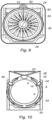
- THE figure 6 , 7 , 8 And 9 present the industrial truck 30 comprising on each side a vertical upright 54 located behind the front cowls 8, at the level of the movable rear cowls of the thrust reverser which are dismantled. At this level, the width of the nacelle is reduced, which makes it possible to arrange the vertical uprights 54 slightly set back from the total external lateral bulk of the nacelle given by the front covers 8 remaining assembled.
- Each vertical upright 54 is rigidly fixed to the base of the carriage 30, in the lower part by a triangular gusset 58 facing forwards, coming clearly below the horizontal diameter of the nacelle in order to remain within the lateral dimensions of these uprights, and in the upper part by a strut 56 inclined towards the rear.
- the two upper ends of the uprights 54 are connected by an upper crosspiece 62 coming above the nacelle, which gives lateral stability to these uprights.
- each vertical upright 54 comprises two arms facing forwards 60, forming a longitudinally elongated triangle having its small base fixed to this upright.
- the front end of the arms 60 receives a quick attachment of an upper handling yoke 24 installed on the turbojet engine.
- a transverse lower crosspiece 26 upstream is fixed to the lower support points 16.
- the carriage also comprises a transverse lower crosspiece 27 downstream.
- a link 32 there is placed on the carriage 30, in the chain of elements connecting the upper lifting points 14 to the lower support points 16, a link 32 making it possible to take up play due to small differences in geometry between that of the turbojet engine and that of the this cart.
- slightly elastic elements, clearances or adjustment ranges can be provided.
- the vertical uprights 54 can also be linked to the base of the carriage 30 by longitudinal pivots, like the articulated arms 34 presented on the first type of carriage, or be removable.
- FIG 10 presents as a variant a carriage 30 not using the lower transverse beam 26, which comprises vertical uprights 54 which are sufficiently rigid to carry the front mass of the motorization assembly. With this carriage there is no need to provide a lower support point 16 on the turbojet engine.
Landscapes
- Engineering & Computer Science (AREA)
- Aviation & Aerospace Engineering (AREA)
- Mechanical Engineering (AREA)
- General Engineering & Computer Science (AREA)
- Transportation (AREA)
- Chemical & Material Sciences (AREA)
- Combustion & Propulsion (AREA)
- Manufacturing & Machinery (AREA)
- Structures Of Non-Positive Displacement Pumps (AREA)
- Handcart (AREA)
Description
- La présente invention concerne un ensemble de motorisation pour aéronef, comprenant un moteur tel un turboréacteur et une nacelle équipée d'un inverseur de poussée à grilles, ainsi qu'un chariot de manutention pour cet ensemble.
- Les turboréacteurs de motorisation des aéronefs disposés dans une nacelle, reçoivent de l'air frais venant du côté avant, et rejettent du côté arrière les gaz chauds issus de la combustion du carburant délivrant une poussée.
- Pour les turboréacteurs à double flux, des aubes de soufflante disposées autour du moteur génèrent un flux secondaire important d'air froid le long d'une veine annulaire passant entre ce moteur et la nacelle, qui ajoute une poussée élevée.
- Certaines nacelles comportent un système d'inversion de poussée qui ferme au moins en partie la veine annulaire d'air froid, et rejette le flux secondaire radialement vers l'extérieur en le dirigeant vers l'avant afin de générer une poussée inversée de freinage de l'aéronef.
- Un type d'inverseur de poussée à grilles connu, présenté notamment par le document
US-A1-20160160799 , comporte des grilles d'inversion formant une couronne disposée sous des capots avant, entourant la veine annulaire, qui sont reliées à des capots mobiles arrière coulissant vers l'arrière sous l'effet de vérins. - Dans une position fermée de l'inverseur pour un flux direct, les capots mobiles arrière ferment des passages latéraux vers l'extérieur disposés autour de la veine annulaire.
- Dans une position ouverte de l'inverseur pour un flux inversé, les capots arrière manoeuvrés par des vérins reculent sur des guidages longitudinaux, en entraînant les grilles qui se positionnent dans les passages d'airs latéraux. Des volets de fermeture ferment au moins partiellement le flux secondaire en arrière de ces passages, en refoulant le flux vers les grilles qui inversent la poussée.
- Dans ce cas la surface extérieure de la nacelle est composée en partant de l'avant, d'une section amont comprenant l'entrée d'air, puis une section médiane entourant la soufflante, présentant des capots avant amovibles pour la maintenance, et ensuite une section arrière ou aval recouverte par les capots mobiles de l'inverseur de poussée.
- Les capots avant couvrant le tour de la nacelle, peuvent comporter en particulier des capots latéraux, un capot du dessous, et un capot du dessus disposé dans la continuité d'un capotage du pylône de suspension du turboréacteur. Le pylône de suspension permet de suspendre la motorisation à une aile de l'aéronef.
- En outre, le moteur comporte des points de suspension généralement disposés à 12 h, qui sont configurés pour recevoir des chapes de suspension permettant de fixer le pylône de suspension au moteur.
- Les différents capots avant comportent des systèmes de démontage permettant de les faire pivoter ou de les déposer complètement afin d'accéder aux éléments dans la nacelle, en particulier à la motorisation, pour des opérations de maintenance. Par ailleurs la motorisation comporte des points de levage disposés sur son pourtour, formant des points résistants d'accrochage recevant des chapes de manutention permettant de soulever et de transporter la motorisation complète avec sa nacelle.
- Un type de chariot de transport connu, présenté notamment par le document
US-A1-20150316197 , comporte de chaque côté un bras de fixation monté sur un pivot disposé suivant la direction longitudinale de la motorisation. Les deux bras s'écartent vers l'extérieur du chariot pour laisser entre eux la place afin de descendre la nacelle comprenant la motorisation, sur laquelle on a retiré des capots avant afin de dégager les points de levage latéraux du turboréacteur. Puis on referme ces deux bras sur la nacelle, en engageant un arbre fixé à l'extrémité de chaque bras sur un de ces points de levage qui est disposé à trois heures ou à neuf heures. - On obtient après un verrouillage des bras, une suspension du turboréacteur avec sa nacelle en deux points latéraux diamétralement opposés, disposés suivant une direction horizontale, qui maintiennent un équilibre de la motorisation.
- Un inconvénient de ces motorisations est qu'elles nécessitent un temps important pour démonter des capots avant permettant de dégager des zones suffisamment larges devant les points de levage.
- De plus les structures de levage et de transport, comme le chariot de transport présenté ci-dessus, occupent un espace latéral qui déborde de la largeur de la nacelle, afin de disposer les bras venant sur les côtés de cette nacelle pour prendre les points de levage latéraux. Cette largeur occupée pose des problèmes de manutention et de transport d'autant plus importants que les motorisations modernes tendent à augmenter le taux de dilution par la soufflante, ce qui entraîne un diamètre plus important de cette soufflante, et des bras plus écartés. Le document
WO 2015/114276 A1 divulgue un chariot de manutention portant un ensemble de motorisation dont le capotage cylindrique externe de nacelle a été retiré. - La présente invention a notamment pour but d'éviter ces inconvénients de la technique antérieure.
- Elle propose à cet effet un ensemble de motorisation selon la revendication 1.
- Un avantage de cet ensemble de motorisation est qu'après avoir dégagé les points de levage disposés derrière les capots avant, en ouvrant les trappes formées dans ces capots, grâce à la disposition de ces points de levage au-dessus du diamètre horizontal on peut installer sur chaque point une chape de manutention recevant un bras de reprise qui vient du haut ou de l'arrière, mais sans dépasser latéralement du diamètre extérieur horizontal de la nacelle. On obtient un encombrement total en largeur de la structure de levage ou de manutention qui ne dépasse pas de la largeur de la nacelle, ce qui facilite les transports de cet ensemble.
- L'ensemble de motorisation selon l'invention peut comporter une ou plusieurs des caractéristiques suivantes, qui peuvent être combinées entre elles.
- L'ensemble de motorisation comporte des points de suspension à un pylône.
- Selon la revendication 1, chaque capot avant latéral comporte une trappe amovible et mobile entre une position fermée dans laquelle la trappe affleure ledit capot et une position ouverte dans laquelle la trappe ouvre l'accès à un point de levage supérieur, disposée radialement à l'extérieur du point de levage supérieur de son côté. Chaque trappe amovible est configurée pour être ouverte pour donner accès aux points de levage supérieurs pour la manutention de l'ensemble de motorisation. De cette manière on évite la dépose de capots avant complets pour la manutention de l'ensemble de motorisation. Les trappes amovibles sont des trappes aptes à être ouvertes et peuvent être par exemple des trappes coulissantes ou pivotantes ou des trappes aptes à être retirées des capots.
- Par « amovible » on entend coulissant, pivotant ou apte à être retiré au moins partiellement.
- L'ensemble de motorisation comporte une chape de manutention fixée sur chaque point de levage supérieur lorsque les trappes amovibles sont ouvertes et l'inverseur de poussée est ouvert.
- Avantageusement, chaque point de levage supérieur est disposé dans un plan transversal à l'intérieur d'un secteur angulaire centré sur l'axe de la nacelle, compris entre 20 et 40° au-dessus du diamètre horizontal de cette nacelle. Avec cet angle on répartit les efforts de levage de chaque côté de la nacelle, en permettant la pose de chapes de manutention sur ces points de levage dirigées radialement vers l'extérieur, qui ne dépassent pas de l'encombrement transversal de la nacelle.
- Avantageusement, la nacelle comporte un capot avant inférieur et le moteur tel que le turboréacteur comporte deux points de support inférieurs disposés chacun radialement derrière le capot avant inférieur.
- L'invention a aussi pour objet un chariot selon la revendication 6, remarquable en ce qu'il est configuré pour présenter dans la direction transversale une largeur totale inférieure à la largeur maximum de l'ensemble de motorisation. De cette manière le chariot n'augmente pas la largeur de la nacelle pendant son transport.
- Le chariot présente donc dans la direction transversale une largeur totale inférieure à la largeur maximum de l'ensemble de motorisation.
- Selon un mode de réalisation, le chariot comporte de chaque côté un bras articulé comportant une partie inférieure reliée par un pivot à la base du chariot, et une partie supérieure comportant un point d'appui venant se fixer sur un point de levage supérieur.
- Selon un autre mode de réalisation, le chariot comporte de chaque côté un montant disposé en arrière des capots avant latéraux, relié en partie supérieure à un point de levage supérieur.
- Dans ce cas, avantageusement chaque montant comporte en arrière dans la direction longitudinale, une jambe de force prenant appui sur la base du chariot en arrière de ce montant.
- De plus, avantageusement chaque montant comporte en avant dans la direction longitudinale, en partie supérieure des bras allongés vers l'avant reliés à leurs extrémités avant à un point de levage supérieur.
- Avantageusement, les bras articulés ou les montants sont démontables.
- En complément, le chariot peut comporter une traverse inférieure transversale de transport amont, se fixant sous des points de support inférieurs du moteur, en particulier du turboréacteur.
- Avantageusement, le chariot comprend des points d'appui pour les points de levage supérieurs et/ou les points de support inférieurs. Il comporte entre ces points d'appui une liaison permettant de rattraper des jeux dus à des différences de géométrie entre celle du moteur tel que le turboréacteur et celle de ce chariot.
- L'invention a aussi pour objet un ensemble de transport de moteur comprenant un ensemble de motorisation et un chariot portant l'ensemble de motorisation comprenant l'une quelconque des caractéristiques précédentes.
- Selon une caractéristique, le chariot comporte de chaque côté un bras articulé ou un montant étant relié à l'un des points de levage supérieurs par l'intermédiaire d'une chape de manutention fixée sur ce point de levage supérieur.
- L'invention sera mieux comprise et d'autres caractéristiques et avantages apparaîtront plus clairement à la lecture de la description ci-après donnée à titre d'exemple, en référence aux dessins annexés dans lesquels :
- la
figure 1 est un schéma en coupe transversale d'un ensemble de motorisation selon l'invention, selon un plan de coupe passant par des points de levage et de support disposés derrière des capots avant ; - les
figures 2, 3 ,4, et 5 présentent dans le même plan de coupe, différentes étapes d'utilisation d'un premier type de chariot adapté pour cet ensemble de motorisation ; - les
figures 6 ,7 ,8 et9 présentent successivement en coupe transversale, de côté, de face avec une petite inclinaison et de face, un deuxième type de chariot adapté pour cet ensemble de motorisation ; et - la
figure 10 présente en coupe transversale une variante de ce deuxième type de chariot ne comportant pas de poutre inférieure de transport. - Pour plus de clarté, les éléments identiques ou similaires sont repérés par des signes de référence identiques sur l'ensemble des figures.
- La
figure 1 présente une nacelle contenant un turboréacteur à double flux 4 supporté par un pylône 2 disposé à 12h. - A cet effet, le turboréacteur comprend des points de suspensions 13 configurés pour recevoir des chapes de suspension 13' permettant de fixer le turboréacteur au pylône 2.
- Chaque côté du turboréacteur 4 est entouré par un ensemble de grilles d'inversion de poussée 6, qui dans une position fermée de l'inverseur de poussée se trouve radialement derrière des capots avant 8, 10 formant la surface extérieure aérodynamique de la nacelle.
- Les capots avant comportent de manière symétrique par rapport à un axe vertical, des capots latéraux 8 couvrant une grande partie des côtés, un capot inférieur 10, et un capot supérieur 12 comprenant un capotage aérodynamique dans le prolongement d'un pylône de suspension 2 fixé sous un aéronef. Le contour extérieur du turboréacteur 4 comporte des points de levage 14 et des points de support 16 solidement fixés à ce turboréacteur pour supporter sa masse, et disposés respectivement en partie supérieure nettement au-dessus d'un diamètre horizontal, dans des positions à environ 60 et 300°, appelées aussi positions 2h et 10h, et en partie inférieure dans des positions à environ 145 et 215°, proches des positions 5h et 7h. Ces points de levage sont distincts des points de fixation décrits plus haut. Les points de levage se distinguent par le fait qu'ils sont dimensionnés pourtransmettent des charges inférieures à celle des points de suspension. Comme cela apparaîtra plus loin dans la description ces points de levage ont un rôle lors de phase de maintenance statique du moteur et à ce titre les efforts qui vont transiter par ces points sont très inférieurs à ceux qui transitent par les points de suspension en phase d'utilisation de l'ensemble de motorisation.
- Par définition, et de façon classique en soi, les points de levage 14 sont aptes à recevoir des chapes de manutention 24 (
figure 2 ) permettant de soulever et de transporter la motorisation complète avec sa nacelle. Les chapes de manutention 24 sont préférablement des éléments rapportés destinés à être retirés une fois que l'ensemble de motorisation est fixé au pylône de suspension 2 au niveau des points de suspension 13. - Chaque capot latéral 4 comporte en partie supérieure une trappe amovible 18 et mobile entre une position fermée dans laquelle la trappe affleure ledit capot et une position ouverte dans laquelle la trappe ouvre l'accès à un point de levage supérieur 14, disposée radialement devant un point de levage supérieur 14. La trappe amovible est apte à être complètement retirée du capot latéral 4. Les points de support inférieurs 16 sont disposés derrière le capot inférieur 10.
- De cette manière en ouvrant de manière rapide les trappes amovibles 18, représentant des petits éléments faciles à stocker, on accède aux points de levage supérieurs 14. En particulier les points de levage 14 et les points de support 16 représentent des fixations résistantes qui peuvent recevoir des éléments techniques appliquant des efforts, comme des vérins de déplacement des grilles d'inversion 6, les trappes amovibles 18 disposées en regard facilitent alors des travaux de maintenance sur ces éléments techniques.
- La
figure 2 présente après l'ouverture des trappes 18 sans déposer les capots latéraux 8, et l'ouverture de l'inverseur de poussée pour reculer ses grilles 6 afin de dégager les points de levage 14 se trouvant derrière, la fixation d'une chape de manutention 24 sur chaque point de levage 14. De même le capot inférieur 10 est déposé pour fixer une poutre de transport inférieure transversale 26 sur les deux points de support inférieurs 16. - Un palan de levage 20 fixé au pylône 2 de l'aéronef, comporte de chaque côté un bras 28 s'étendant dans la largeur, présentant une extrémité venant au-dessus de la chape de manutention 24, pour recevoir un câble de suspension 22 fixé à cette chape.
- La
figure 3 présente un chariot de transport 30 comportant de chaque côté un bras articulé 34 qui pivote dans un plan transversal grâce à un pivot 36 disposé à sa base, présentant un axe longitudinal fixé sur le côté du chariot. - Le bras articulé 34 comporte une partie inférieure reliée par le pivot 36 à la base du chariot 30, et une partie supérieure comportant un point d'appui 38 venant se fixer sur un point de levage supérieur 14.
- En écartant les deux bras articulés 34, on dégage entre ces bras un espace disponible pour avancer le chariot 30 et le disposer sous la nacelle. Ensuite on rapproche les deux bras 34 vers l'axe de la nacelle, pour ajuster de chaque côté un point d'ancrage supérieur 30 de ce bras sur la chape de manutention 24, puis pour se fixer dessus grâce à un système de verrouillage rapide.
- On peut ensuite détacher le palan de levage 20 des chapes de manutention 24, pour emporter le chariot 30 posé sur des roues de déplacement, avec le système de motorisation complet qui a subi un minimum de démontage de ses capots avant.
- La
figure 4 présente le chariot de manutention 30 apporté ensuite, supportant l'ensemble de motorisation, après la dépose de ses bras articulés 34 en détachant les pivots 36 maintenant ces bras sur le chariot, qui comporte un encombrement transversal minimum lui permettant en particulier d'entrer dans une section de passage minimum 40. Cette section de passage 40 peut représenter en particulier la section de passage d'une porte cargo d'un avion, d'un container ou d'une remorque de camion. - Pendant le déplacement du chariot de manutention 30 on emporte avec lui les bras articulés 34, pour les fixer à nouveau sur ce chariot lors d'opérations ultérieures.
- On notera que les chapes de manutention 24 disposées nettement au-dessus du diamètre horizontal D de la nacelle, avantageusement dans un secteur angulaire centré sur l'axe de la nacelle, compris entre 20 et 40° au-dessus de ce diamètre, en particulier suivant un angle de 30°, peuvent dépasser à l'extérieur du contour de cette nacelle sans pour autant sortir de sa largeur totale.
- La
figure 5 présente si nécessaire la dépose des panneaux latéraux 8 de la nacelle afin d'effectuer des opérations de maintenance derrière ces panneaux, qui peut se faire avec les bras articulés 34 restant en place sur le chariot 30, en les écartant seulement ce qui réduit les opérations de démontage. - L'ouverture des bras 34 est suffisante pour permettre un écartement des panneaux latéraux 8 les dégageant des chapes de manutention 24, puis un déplacement de ces panneaux vers le haut ou dans la direction longitudinale pour les sortir.
- La
figure 7 présente un chariot de manutention 30 recevant un ensemble de motorisation, qui est posé sur une plate-forme de déplacement 48 équipée de roues 50, et du côté arrière indiqué par la flèche AR d'un timon de traction 52. - Les
figures 6 ,7 ,8 et9 présentent le chariot de manutention 30 comprenant de chaque côté un montant vertical 54 se trouvant en arrière des capots avant 8, au niveau des capots arrière mobiles de l'inverseur de poussée qui sont démontés. A ce niveau la largeur de la nacelle est réduite, ce qui permet de disposer les montants verticaux 54 légèrement en retrait de l'encombrement latéral extérieur total de la nacelle donné par les capots avant 8 restant assemblés. - Chaque montant vertical 54 est rigidement fixé à la base du chariot 30, en partie inférieure par un gousset triangulaire 58 tourné vers l'avant, venant nettement en dessous du diamètre horizontal de la nacelle afin de rester dans l'encombrement latéral de ces montants, et en partie supérieure par une jambe de force 56 inclinée vers l'arrière.
- Les deux extrémités supérieures des montants 54 sont reliées par une traverse supérieure 62 venant au-dessus de la nacelle, qui donne de la stabilité latérale à ces montants.
- En partie supérieure le côté avant de chaque montant vertical 54 comporte deux bras tournés vers l'avant 60, formant un triangle allongé longitudinalement présentant sa petite base fixée à ce montant. L'extrémité avant des bras 60 reçoit une fixation rapide d'une chape de manutention supérieure 24 installée sur le turboréacteur. Une traverse inférieure transversale 26 amont est fixée sur les points de support inférieurs 16. Le chariot comprend également une traverse inférieure transversale 27 aval.
- Le raidissement important dans la direction longitudinale des montants verticaux 54, grâce aux goussets avant 58 et aux jambes de force arrière 56, permet à ces montants de résister à la charge importante de l'ensemble de motorisation appliquée en porte-à-faux à l'extrémité avant des bras 60.
- Avantageusement on dispose sur le chariot 30, dans la chaîne d'éléments reliant les points de levage supérieurs 14 aux points de support inférieurs 16, une liaison 32 permettant de rattraper des jeux dus à des petites différences de géométrie entre celle du turboréacteur et celle de ce chariot. On peut en particulier prévoir des éléments légèrement élastiques, des jeux ou des plages de réglage.
- En option les montants verticaux 54 peuvent aussi être liés à la base du chariot 30 par des pivots longitudinaux, comme les bras articulés 34 présentés sur le premier type de chariot, ou être démontables.
- La
figure 9 présente la section de passage minimum 40 nécessaire pour l'ensemble de motorisation, qui est équivalente à celle donnée par le premier type de chariot. - La
figure 10 présente en variante un chariot 30 n'utilisant pas la poutre inférieure transversale 26, qui comporte des montants verticaux 54 suffisamment rigides pour porter la masse avant de l'ensemble de motorisation. Avec ce chariot on n'a pas besoin de prévoir de point de support inférieur 16 sur le turboréacteur.
Claims (14)
- Ensemble de motorisation comportant un moteur tel un turboréacteur à double flux (4), et une nacelle comprenant à l'extérieur autour d'une veine annulaire d'air frais, en partant de l'amont, une entrée d'air, des capots avant latéraux (8), un inverseur de poussée comprenant des grilles d'inversion (6) et des capots arrières mobiles, les capots avant latéraux (8) entourant les grilles d'inversion (6) de l'inverseur de poussée quand il est fermé, et les capots arrière mobiles reculant avec ces grilles (6) pour ouvrir l'inverseur, le moteur comportant des points de levage (14) formant des points résistants d'accrochage destinés à recevoir des chapes de manutention permettant de soulever et de transporter l'ensemble de motorisation, l'ensemble de motorisation étant tel que les points de levage (14) sont deux points de levage supérieurs (14) disposés sur le moteur, chacun d'un côté du moteur radialement derrière les capots avant latéraux (8) au-dessus du diamètre horizontal (D) de l'ensemble de motorisation, et tel que chaque capot avant latéral (8) comporte une trappe amovible (18) et mobile entre une position fermée dans laquelle la trappe affleure ledit capot et une position ouverte dans laquelle la trappe ouvre l'accès à un point de levage supérieur (14), disposée radialement à l'extérieur du point de levage supérieur (14) de son côté.
- Ensemble de motorisation selon la revendication 1, caractérisé en ce qu'il comporte des points de suspension (13) à un pylône.
- Ensemble de motorisation selon l'une quelconque des revendications précédentes, caractérisé en ce qu'il comporte une chape de manutention (24) fixée sur chaque point de levage supérieur (14) lorsque les trappes amovibles (18) sont ouvertes et l'inverseur de poussée (6) est ouvert.
- Ensemble de motorisation selon l'une des revendications précédentes, caractérisé en ce que chaque point de levage supérieur (14) est disposé dans un plan transversal à l'intérieur d'un secteur angulaire centré sur l'axe de la nacelle, compris entre 20 et 40° au-dessus du diamètre horizontal (D) de cette nacelle.
- Ensemble de motorisation selon l'une quelconque des revendications précédentes, caractérisé en ce que la nacelle comporte un capot avant inférieur (10) et le moteur tel que le turboréacteur comporte deux points de support inférieurs (16) disposés chacun radialement derrière le capot avant inférieur (10).
- Chariot configuré pour transporter un ensemble de motorisation selon l'une quelconque des revendications précédentes, le chariot étant configuré pour présenter dans la direction transversale une largeur totale inférieure à la largeur maximum de l'ensemble de motorisation.
- Chariot selon la revendication précédente, caractérisé en ce qu'il comporte de chaque côté un bras articulé (34) comportant une partie inférieure reliée par un pivot (36) à la base du chariot (30), et une partie supérieure comportant un point d'appui (38) venant se fixer sur un point de levage supérieur (14).
- Chariot selon la revendication 6, caractérisé en ce qu'il comporte de chaque côté un montant (54) disposé en arrière des capots avant latéraux (8), relié en partie supérieure à un point de levage supérieur (14).
- Chariot selon la revendication précédente, caractérisé en ce que chaque montant (54) comporte en arrière dans la direction longitudinale, une jambe de force (56) prenant appui sur la base du chariot (30) en arrière de ce montant (54).
- Chariot selon la revendication 8 ou 9, caractérisé en ce que chaque montant (54) comporte en avant dans la direction longitudinale, en partie supérieure des bras allongés vers l'avant (60) reliés à leurs extrémités avant à un point de levage supérieur (14).
- Chariot selon l'une quelconque des revendications 7 à 10, caractérisé en ce que les bras articulés (34) ou les montants (54) sont démontables.
- Chariot selon l'une quelconque des revendications 6 à 11 configuré pour transporter un ensemble de motorisation selon la revendication 5, caractérisé en ce qu'il comporte une traverse inférieure transversale de transport amont (26), se fixant sous les points de support inférieurs (16) du moteur.
- Chariot selon l'une quelconque des revendications 6 à 12 configuré pour transporter un ensemble de motorisation selon la revendication 5, comprenant des points d'appui pour les points de levage supérieurs (14) et des points d'appui pour les points de support inférieurs (16), caractérisé en ce qu'il comporte entre ces points d'appui une liaison (32) permettant de rattraper des jeux dus à des différences de géométrie entre celle du moteur et celle de ce chariot (30).
- Ensemble de transport de moteur, comprenant un ensemble de motorisation selon l'une quelconque des revendications 1 à 5 et un chariot selon l'une quelconque des revendications 6 à 13 portant l'ensemble de motorisation.
Applications Claiming Priority (2)
| Application Number | Priority Date | Filing Date | Title |
|---|---|---|---|
| FR1851445A FR3078058B1 (fr) | 2018-02-20 | 2018-02-20 | Ensemble de motorisation pour aeronef comportant des points de levage, et chariots pour supporter un tel ensemble |
| PCT/FR2019/050380 WO2019162611A1 (fr) | 2018-02-20 | 2019-02-19 | Ensemble de motorisation pour aeronef comportant des points de levage, et chariots pour supporter un tel ensemble |
Publications (2)
| Publication Number | Publication Date |
|---|---|
| EP3755627A1 EP3755627A1 (fr) | 2020-12-30 |
| EP3755627B1 true EP3755627B1 (fr) | 2023-05-10 |
Family
ID=62222905
Family Applications (1)
| Application Number | Title | Priority Date | Filing Date |
|---|---|---|---|
| EP19711970.4A Active EP3755627B1 (fr) | 2018-02-20 | 2019-02-19 | Ensemble de motorisation pour aeronef comportant des points de levage, et chariots pour supporter un tel ensemble |
Country Status (5)
| Country | Link |
|---|---|
| US (1) | US11834187B2 (fr) |
| EP (1) | EP3755627B1 (fr) |
| CN (1) | CN111741900B (fr) |
| FR (1) | FR3078058B1 (fr) |
| WO (1) | WO2019162611A1 (fr) |
Families Citing this family (3)
| Publication number | Priority date | Publication date | Assignee | Title |
|---|---|---|---|---|
| FR3085358B1 (fr) * | 2018-08-31 | 2020-09-25 | Safran Nacelles | Ensemble et procede de manutention d’un ensemble propulsif d’aeronef |
| US12459669B2 (en) | 2020-08-19 | 2025-11-04 | Safran Aero Boosters | Cart for assembling and transporting an aircraft engine to a test cell |
| EP4257481A1 (fr) * | 2022-04-05 | 2023-10-11 | Rohr, Inc. | Raccord de structure d'entrée de nacelle avec attache de positionnement et support de levage |
Family Cites Families (12)
| Publication number | Priority date | Publication date | Assignee | Title |
|---|---|---|---|---|
| RU2007345C1 (ru) | 1992-02-18 | 1994-02-15 | Юрий Семенович Соломонов | Способ сборки ступеней многоступенчатого летательного аппарата с секциями транспортно-пускового контейнера |
| FR2902839B1 (fr) * | 2006-06-21 | 2011-09-30 | Aircelle Sa | Inverseur de poussee formant une tuyere adaptative |
| FR2917710A1 (fr) * | 2007-06-22 | 2008-12-26 | Aircelle Sa | Platine de fixation et longeron de manutention d'ensemble propulsif monobloc d'un aeronef |
| FR2922498B1 (fr) | 2007-10-23 | 2012-03-30 | Aircelle Sa | Chariot de maintenance pour entree d'air de nacelle pour turboreacteur d'aeronef |
| FR2936493A1 (fr) * | 2008-10-01 | 2010-04-02 | Aircelle Sa | Mat adapte pour supporter un turboracteur d'aeronef et nacelle associee a un mat. |
| US8683670B2 (en) * | 2010-12-20 | 2014-04-01 | Turbine Tooling Solutions Llc | Method for partial disassembly of a bypass turbofan engine |
| FR2983836B1 (fr) * | 2011-12-08 | 2014-12-19 | Airbus Operations Sas | Outillage d'aide a la construction et a la maintenance des aeronefs |
| CN103112595B (zh) * | 2013-02-06 | 2016-01-27 | 中国商用飞机有限责任公司 | 推进系统一体化的吊挂结构 |
| FR3017112B1 (fr) * | 2014-02-03 | 2017-09-29 | Snecma | Structure de transport et de hissage pour turbomachine |
| WO2015168637A1 (fr) | 2014-05-02 | 2015-11-05 | Morey Joel T | Support pour moteur d'avion |
| FR3023324B1 (fr) * | 2014-07-01 | 2020-04-24 | Safran Nacelles | Inverseur de poussee d’une nacelle de turboreacteur, comprenant des decoupes d’evitement du bec mobile de l’aile |
| US10309343B2 (en) | 2014-11-06 | 2019-06-04 | Rohr, Inc. | Split sleeve hidden door thrust reverser |
-
2018
- 2018-02-20 FR FR1851445A patent/FR3078058B1/fr active Active
-
2019
- 2019-02-19 CN CN201980014353.8A patent/CN111741900B/zh active Active
- 2019-02-19 WO PCT/FR2019/050380 patent/WO2019162611A1/fr not_active Ceased
- 2019-02-19 EP EP19711970.4A patent/EP3755627B1/fr active Active
-
2020
- 2020-08-20 US US16/998,893 patent/US11834187B2/en active Active
Also Published As
| Publication number | Publication date |
|---|---|
| US20200377221A1 (en) | 2020-12-03 |
| US11834187B2 (en) | 2023-12-05 |
| FR3078058A1 (fr) | 2019-08-23 |
| RU2020126683A (ru) | 2022-03-21 |
| CN111741900A (zh) | 2020-10-02 |
| FR3078058B1 (fr) | 2022-03-25 |
| EP3755627A1 (fr) | 2020-12-30 |
| CN111741900B (zh) | 2023-07-04 |
| WO2019162611A1 (fr) | 2019-08-29 |
Similar Documents
| Publication | Publication Date | Title |
|---|---|---|
| CA2689111C (fr) | Ensemble moteur pour aeronef a nacelle coulissante | |
| EP1905689B1 (fr) | Système propusif intégré comportant un moteur à turboreacteur à double flux | |
| CA2602176C (fr) | Systeme propulsif a pylone integre pour avion | |
| EP3755627B1 (fr) | Ensemble de motorisation pour aeronef comportant des points de levage, et chariots pour supporter un tel ensemble | |
| FR2903666A1 (fr) | Ensemble moteur pour aeronef comprenant un capotage aerodynamique de jonction monte sur deux elements distincts | |
| FR2622930A1 (fr) | Capotage pour turboreacteur a double flux | |
| EP2035279A1 (fr) | Nacelle structurante | |
| EP3755887B1 (fr) | Ensemble propulsif comportant des points de levage disposés sur des supports de vérins d'inverseur de poussée | |
| FR2901245A1 (fr) | Dispositif d'articulation d'une porte d'une nacelle d'aeronef et nacelle equipee dudit dispositif d'articulation | |
| EP2602193B1 (fr) | Outillage d'aide à la construction et à la maintenance des aéronefs | |
| FR3024435A1 (fr) | Capot de soufflante pliable guide, pour ensemble moteur d'aeronef | |
| FR3040369A1 (fr) | Ensemble moteur d'aeronef comprenant une attache moteur avant amelioree | |
| EP3247635A1 (fr) | Système pour la pose et la dépose d'un ensemble propulsif sur un mât d'un aéronef | |
| WO2012045965A1 (fr) | Ensemble propulsif d'aéronef | |
| WO2015185811A1 (fr) | Ensemble de manutention d'un moteur d'aéronef | |
| EP3728799B1 (fr) | Nacelle de turboréacteur comportant des ouvertures de capots avant d'accès à des points de fixation de la nacelle | |
| FR3043648A1 (fr) | Voilure propulsive d'un aeronef | |
| EP3728041A1 (fr) | Ensemble de capot ouvrant et mécanisme de deploiement | |
| FR3075174A1 (fr) | Structure porteuse destinee au montage sur un generateur de gaz | |
| FR3020338A1 (fr) | Partie arriere d'aeronef pourvue d'une structure de support des moteurs de forme optimisee | |
| RU2775952C2 (ru) | Приводной блок для летательного аппарата, содержащий точки подъема, и тележка для поддержки такого блока | |
| FR3038885A1 (fr) | Aeronef avec entree d'air centrale | |
| FR2897591A1 (fr) | Dispositif de fixation de trains d'atterissage principaux pour un avion en configuration de voilure basse avec installation motrice sous voilure |
Legal Events
| Date | Code | Title | Description |
|---|---|---|---|
| STAA | Information on the status of an ep patent application or granted ep patent |
Free format text: STATUS: UNKNOWN |
|
| STAA | Information on the status of an ep patent application or granted ep patent |
Free format text: STATUS: THE INTERNATIONAL PUBLICATION HAS BEEN MADE |
|
| PUAI | Public reference made under article 153(3) epc to a published international application that has entered the european phase |
Free format text: ORIGINAL CODE: 0009012 |
|
| STAA | Information on the status of an ep patent application or granted ep patent |
Free format text: STATUS: REQUEST FOR EXAMINATION WAS MADE |
|
| 17P | Request for examination filed |
Effective date: 20200827 |
|
| AK | Designated contracting states |
Kind code of ref document: A1 Designated state(s): AL AT BE BG CH CY CZ DE DK EE ES FI FR GB GR HR HU IE IS IT LI LT LU LV MC MK MT NL NO PL PT RO RS SE SI SK SM TR |
|
| AX | Request for extension of the european patent |
Extension state: BA ME |
|
| DAV | Request for validation of the european patent (deleted) | ||
| DAX | Request for extension of the european patent (deleted) | ||
| GRAP | Despatch of communication of intention to grant a patent |
Free format text: ORIGINAL CODE: EPIDOSNIGR1 |
|
| STAA | Information on the status of an ep patent application or granted ep patent |
Free format text: STATUS: GRANT OF PATENT IS INTENDED |
|
| INTG | Intention to grant announced |
Effective date: 20220708 |
|
| GRAJ | Information related to disapproval of communication of intention to grant by the applicant or resumption of examination proceedings by the epo deleted |
Free format text: ORIGINAL CODE: EPIDOSDIGR1 |
|
| STAA | Information on the status of an ep patent application or granted ep patent |
Free format text: STATUS: REQUEST FOR EXAMINATION WAS MADE |
|
| GRAP | Despatch of communication of intention to grant a patent |
Free format text: ORIGINAL CODE: EPIDOSNIGR1 |
|
| STAA | Information on the status of an ep patent application or granted ep patent |
Free format text: STATUS: GRANT OF PATENT IS INTENDED |
|
| INTC | Intention to grant announced (deleted) | ||
| INTG | Intention to grant announced |
Effective date: 20221130 |
|
| GRAS | Grant fee paid |
Free format text: ORIGINAL CODE: EPIDOSNIGR3 |
|
| GRAA | (expected) grant |
Free format text: ORIGINAL CODE: 0009210 |
|
| STAA | Information on the status of an ep patent application or granted ep patent |
Free format text: STATUS: THE PATENT HAS BEEN GRANTED |
|
| AK | Designated contracting states |
Kind code of ref document: B1 Designated state(s): AL AT BE BG CH CY CZ DE DK EE ES FI FR GB GR HR HU IE IS IT LI LT LU LV MC MK MT NL NO PL PT RO RS SE SI SK SM TR |
|
| REG | Reference to a national code |
Ref country code: GB Ref legal event code: FG4D Free format text: NOT ENGLISH |
|
| REG | Reference to a national code |
Ref country code: AT Ref legal event code: REF Ref document number: 1566465 Country of ref document: AT Kind code of ref document: T Effective date: 20230515 Ref country code: CH Ref legal event code: EP |
|
| REG | Reference to a national code |
Ref country code: DE Ref legal event code: R096 Ref document number: 602019028714 Country of ref document: DE |
|
| REG | Reference to a national code |
Ref country code: IE Ref legal event code: FG4D Free format text: LANGUAGE OF EP DOCUMENT: FRENCH |
|
| REG | Reference to a national code |
Ref country code: LT Ref legal event code: MG9D |
|
| REG | Reference to a national code |
Ref country code: AT Ref legal event code: MK05 Ref document number: 1566465 Country of ref document: AT Kind code of ref document: T Effective date: 20230510 |
|
| PG25 | Lapsed in a contracting state [announced via postgrant information from national office to epo] |
Ref country code: SE Free format text: LAPSE BECAUSE OF FAILURE TO SUBMIT A TRANSLATION OF THE DESCRIPTION OR TO PAY THE FEE WITHIN THE PRESCRIBED TIME-LIMIT Effective date: 20230510 Ref country code: PT Free format text: LAPSE BECAUSE OF FAILURE TO SUBMIT A TRANSLATION OF THE DESCRIPTION OR TO PAY THE FEE WITHIN THE PRESCRIBED TIME-LIMIT Effective date: 20230911 Ref country code: NO Free format text: LAPSE BECAUSE OF FAILURE TO SUBMIT A TRANSLATION OF THE DESCRIPTION OR TO PAY THE FEE WITHIN THE PRESCRIBED TIME-LIMIT Effective date: 20230810 Ref country code: NL Free format text: LAPSE BECAUSE OF FAILURE TO SUBMIT A TRANSLATION OF THE DESCRIPTION OR TO PAY THE FEE WITHIN THE PRESCRIBED TIME-LIMIT Effective date: 20230510 Ref country code: ES Free format text: LAPSE BECAUSE OF FAILURE TO SUBMIT A TRANSLATION OF THE DESCRIPTION OR TO PAY THE FEE WITHIN THE PRESCRIBED TIME-LIMIT Effective date: 20230510 Ref country code: AT Free format text: LAPSE BECAUSE OF FAILURE TO SUBMIT A TRANSLATION OF THE DESCRIPTION OR TO PAY THE FEE WITHIN THE PRESCRIBED TIME-LIMIT Effective date: 20230510 |
|
| PG25 | Lapsed in a contracting state [announced via postgrant information from national office to epo] |
Ref country code: RS Free format text: LAPSE BECAUSE OF FAILURE TO SUBMIT A TRANSLATION OF THE DESCRIPTION OR TO PAY THE FEE WITHIN THE PRESCRIBED TIME-LIMIT Effective date: 20230510 Ref country code: PL Free format text: LAPSE BECAUSE OF FAILURE TO SUBMIT A TRANSLATION OF THE DESCRIPTION OR TO PAY THE FEE WITHIN THE PRESCRIBED TIME-LIMIT Effective date: 20230510 Ref country code: LV Free format text: LAPSE BECAUSE OF FAILURE TO SUBMIT A TRANSLATION OF THE DESCRIPTION OR TO PAY THE FEE WITHIN THE PRESCRIBED TIME-LIMIT Effective date: 20230510 Ref country code: LT Free format text: LAPSE BECAUSE OF FAILURE TO SUBMIT A TRANSLATION OF THE DESCRIPTION OR TO PAY THE FEE WITHIN THE PRESCRIBED TIME-LIMIT Effective date: 20230510 Ref country code: IS Free format text: LAPSE BECAUSE OF FAILURE TO SUBMIT A TRANSLATION OF THE DESCRIPTION OR TO PAY THE FEE WITHIN THE PRESCRIBED TIME-LIMIT Effective date: 20230910 Ref country code: HR Free format text: LAPSE BECAUSE OF FAILURE TO SUBMIT A TRANSLATION OF THE DESCRIPTION OR TO PAY THE FEE WITHIN THE PRESCRIBED TIME-LIMIT Effective date: 20230510 Ref country code: GR Free format text: LAPSE BECAUSE OF FAILURE TO SUBMIT A TRANSLATION OF THE DESCRIPTION OR TO PAY THE FEE WITHIN THE PRESCRIBED TIME-LIMIT Effective date: 20230811 |
|
| PG25 | Lapsed in a contracting state [announced via postgrant information from national office to epo] |
Ref country code: FI Free format text: LAPSE BECAUSE OF FAILURE TO SUBMIT A TRANSLATION OF THE DESCRIPTION OR TO PAY THE FEE WITHIN THE PRESCRIBED TIME-LIMIT Effective date: 20230510 |
|
| PG25 | Lapsed in a contracting state [announced via postgrant information from national office to epo] |
Ref country code: SK Free format text: LAPSE BECAUSE OF FAILURE TO SUBMIT A TRANSLATION OF THE DESCRIPTION OR TO PAY THE FEE WITHIN THE PRESCRIBED TIME-LIMIT Effective date: 20230510 |
|
| PG25 | Lapsed in a contracting state [announced via postgrant information from national office to epo] |
Ref country code: SM Free format text: LAPSE BECAUSE OF FAILURE TO SUBMIT A TRANSLATION OF THE DESCRIPTION OR TO PAY THE FEE WITHIN THE PRESCRIBED TIME-LIMIT Effective date: 20230510 Ref country code: SK Free format text: LAPSE BECAUSE OF FAILURE TO SUBMIT A TRANSLATION OF THE DESCRIPTION OR TO PAY THE FEE WITHIN THE PRESCRIBED TIME-LIMIT Effective date: 20230510 Ref country code: RO Free format text: LAPSE BECAUSE OF FAILURE TO SUBMIT A TRANSLATION OF THE DESCRIPTION OR TO PAY THE FEE WITHIN THE PRESCRIBED TIME-LIMIT Effective date: 20230510 Ref country code: EE Free format text: LAPSE BECAUSE OF FAILURE TO SUBMIT A TRANSLATION OF THE DESCRIPTION OR TO PAY THE FEE WITHIN THE PRESCRIBED TIME-LIMIT Effective date: 20230510 Ref country code: DK Free format text: LAPSE BECAUSE OF FAILURE TO SUBMIT A TRANSLATION OF THE DESCRIPTION OR TO PAY THE FEE WITHIN THE PRESCRIBED TIME-LIMIT Effective date: 20230510 Ref country code: CZ Free format text: LAPSE BECAUSE OF FAILURE TO SUBMIT A TRANSLATION OF THE DESCRIPTION OR TO PAY THE FEE WITHIN THE PRESCRIBED TIME-LIMIT Effective date: 20230510 |
|
| REG | Reference to a national code |
Ref country code: DE Ref legal event code: R097 Ref document number: 602019028714 Country of ref document: DE |
|
| PLBE | No opposition filed within time limit |
Free format text: ORIGINAL CODE: 0009261 |
|
| STAA | Information on the status of an ep patent application or granted ep patent |
Free format text: STATUS: NO OPPOSITION FILED WITHIN TIME LIMIT |
|
| 26N | No opposition filed |
Effective date: 20240213 |
|
| PG25 | Lapsed in a contracting state [announced via postgrant information from national office to epo] |
Ref country code: SI Free format text: LAPSE BECAUSE OF FAILURE TO SUBMIT A TRANSLATION OF THE DESCRIPTION OR TO PAY THE FEE WITHIN THE PRESCRIBED TIME-LIMIT Effective date: 20230510 |
|
| PG25 | Lapsed in a contracting state [announced via postgrant information from national office to epo] |
Ref country code: SI Free format text: LAPSE BECAUSE OF FAILURE TO SUBMIT A TRANSLATION OF THE DESCRIPTION OR TO PAY THE FEE WITHIN THE PRESCRIBED TIME-LIMIT Effective date: 20230510 Ref country code: IT Free format text: LAPSE BECAUSE OF FAILURE TO SUBMIT A TRANSLATION OF THE DESCRIPTION OR TO PAY THE FEE WITHIN THE PRESCRIBED TIME-LIMIT Effective date: 20230510 |
|
| PG25 | Lapsed in a contracting state [announced via postgrant information from national office to epo] |
Ref country code: MC Free format text: LAPSE BECAUSE OF FAILURE TO SUBMIT A TRANSLATION OF THE DESCRIPTION OR TO PAY THE FEE WITHIN THE PRESCRIBED TIME-LIMIT Effective date: 20230510 |
|
| REG | Reference to a national code |
Ref country code: CH Ref legal event code: PL |
|
| PG25 | Lapsed in a contracting state [announced via postgrant information from national office to epo] |
Ref country code: LU Free format text: LAPSE BECAUSE OF NON-PAYMENT OF DUE FEES Effective date: 20240219 |
|
| PG25 | Lapsed in a contracting state [announced via postgrant information from national office to epo] |
Ref country code: CH Free format text: LAPSE BECAUSE OF NON-PAYMENT OF DUE FEES Effective date: 20240229 |
|
| PG25 | Lapsed in a contracting state [announced via postgrant information from national office to epo] |
Ref country code: LU Free format text: LAPSE BECAUSE OF NON-PAYMENT OF DUE FEES Effective date: 20240219 Ref country code: CH Free format text: LAPSE BECAUSE OF NON-PAYMENT OF DUE FEES Effective date: 20240229 |
|
| PG25 | Lapsed in a contracting state [announced via postgrant information from national office to epo] |
Ref country code: BG Free format text: LAPSE BECAUSE OF FAILURE TO SUBMIT A TRANSLATION OF THE DESCRIPTION OR TO PAY THE FEE WITHIN THE PRESCRIBED TIME-LIMIT Effective date: 20230510 |
|
| PG25 | Lapsed in a contracting state [announced via postgrant information from national office to epo] |
Ref country code: BG Free format text: LAPSE BECAUSE OF FAILURE TO SUBMIT A TRANSLATION OF THE DESCRIPTION OR TO PAY THE FEE WITHIN THE PRESCRIBED TIME-LIMIT Effective date: 20230510 |
|
| REG | Reference to a national code |
Ref country code: BE Ref legal event code: MM Effective date: 20240229 |
|
| PG25 | Lapsed in a contracting state [announced via postgrant information from national office to epo] |
Ref country code: BE Free format text: LAPSE BECAUSE OF NON-PAYMENT OF DUE FEES Effective date: 20240229 |
|
| PG25 | Lapsed in a contracting state [announced via postgrant information from national office to epo] |
Ref country code: IE Free format text: LAPSE BECAUSE OF NON-PAYMENT OF DUE FEES Effective date: 20240219 |
|
| PG25 | Lapsed in a contracting state [announced via postgrant information from national office to epo] |
Ref country code: IE Free format text: LAPSE BECAUSE OF NON-PAYMENT OF DUE FEES Effective date: 20240219 Ref country code: BE Free format text: LAPSE BECAUSE OF NON-PAYMENT OF DUE FEES Effective date: 20240229 |
|
| PG25 | Lapsed in a contracting state [announced via postgrant information from national office to epo] |
Ref country code: CY Free format text: LAPSE BECAUSE OF FAILURE TO SUBMIT A TRANSLATION OF THE DESCRIPTION OR TO PAY THE FEE WITHIN THE PRESCRIBED TIME-LIMIT; INVALID AB INITIO Effective date: 20190219 |
|
| PG25 | Lapsed in a contracting state [announced via postgrant information from national office to epo] |
Ref country code: HU Free format text: LAPSE BECAUSE OF FAILURE TO SUBMIT A TRANSLATION OF THE DESCRIPTION OR TO PAY THE FEE WITHIN THE PRESCRIBED TIME-LIMIT; INVALID AB INITIO Effective date: 20190219 |
|
| PG25 | Lapsed in a contracting state [announced via postgrant information from national office to epo] |
Ref country code: TR Free format text: LAPSE BECAUSE OF FAILURE TO SUBMIT A TRANSLATION OF THE DESCRIPTION OR TO PAY THE FEE WITHIN THE PRESCRIBED TIME-LIMIT Effective date: 20230510 |
|
| PGFP | Annual fee paid to national office [announced via postgrant information from national office to epo] |
Ref country code: GB Payment date: 20260219 Year of fee payment: 8 |
|
| PGFP | Annual fee paid to national office [announced via postgrant information from national office to epo] |
Ref country code: DE Payment date: 20260217 Year of fee payment: 8 |
|
| PGFP | Annual fee paid to national office [announced via postgrant information from national office to epo] |
Ref country code: FR Payment date: 20260219 Year of fee payment: 8 |