EP3755517B1 - Structural member and/or coupling arrangement and/or method for same - Google Patents
Structural member and/or coupling arrangement and/or method for same Download PDFInfo
- Publication number
- EP3755517B1 EP3755517B1 EP19709779.3A EP19709779A EP3755517B1 EP 3755517 B1 EP3755517 B1 EP 3755517B1 EP 19709779 A EP19709779 A EP 19709779A EP 3755517 B1 EP3755517 B1 EP 3755517B1
- Authority
- EP
- European Patent Office
- Prior art keywords
- beam section
- fitting
- structural member
- nipping sleeve
- nipping
- Prior art date
- Legal status (The legal status is an assumption and is not a legal conclusion. Google has not performed a legal analysis and makes no representation as to the accuracy of the status listed.)
- Active
Links
- 230000008878 coupling Effects 0.000 title claims description 37
- 238000010168 coupling process Methods 0.000 title claims description 37
- 238000005859 coupling reaction Methods 0.000 title claims description 37
- 238000000034 method Methods 0.000 title claims description 11
- 210000002445 nipple Anatomy 0.000 claims description 50
- 238000004873 anchoring Methods 0.000 claims description 27
- 239000004033 plastic Substances 0.000 claims description 16
- 229920003023 plastic Polymers 0.000 claims description 16
- 230000015572 biosynthetic process Effects 0.000 claims description 15
- 238000005755 formation reaction Methods 0.000 claims description 15
- 239000000463 material Substances 0.000 claims description 7
- 239000007924 injection Substances 0.000 claims description 5
- 230000009194 climbing Effects 0.000 claims description 3
- 238000002347 injection Methods 0.000 claims description 3
- 238000000465 moulding Methods 0.000 description 7
- 239000002131 composite material Substances 0.000 description 5
- 238000005516 engineering process Methods 0.000 description 5
- 238000001746 injection moulding Methods 0.000 description 5
- 230000000712 assembly Effects 0.000 description 4
- 238000000429 assembly Methods 0.000 description 4
- 230000003319 supportive effect Effects 0.000 description 4
- 229910052782 aluminium Inorganic materials 0.000 description 3
- XAGFODPZIPBFFR-UHFFFAOYSA-N aluminium Chemical compound [Al] XAGFODPZIPBFFR-UHFFFAOYSA-N 0.000 description 3
- 238000010438 heat treatment Methods 0.000 description 3
- 239000012768 molten material Substances 0.000 description 3
- 229920000049 Carbon (fiber) Polymers 0.000 description 2
- 230000008901 benefit Effects 0.000 description 2
- 238000000748 compression moulding Methods 0.000 description 2
- 238000001125 extrusion Methods 0.000 description 2
- 238000007373 indentation Methods 0.000 description 2
- 238000005304 joining Methods 0.000 description 2
- 238000004519 manufacturing process Methods 0.000 description 2
- 239000011265 semifinished product Substances 0.000 description 2
- 229920001169 thermoplastic Polymers 0.000 description 2
- 239000004416 thermosoftening plastic Substances 0.000 description 2
- 238000009423 ventilation Methods 0.000 description 2
- 239000004593 Epoxy Substances 0.000 description 1
- FYYHWMGAXLPEAU-UHFFFAOYSA-N Magnesium Chemical compound [Mg] FYYHWMGAXLPEAU-UHFFFAOYSA-N 0.000 description 1
- 230000004075 alteration Effects 0.000 description 1
- 239000004917 carbon fiber Substances 0.000 description 1
- 239000011199 continuous fiber reinforced thermoplastic Substances 0.000 description 1
- 230000001419 dependent effect Effects 0.000 description 1
- 230000002708 enhancing effect Effects 0.000 description 1
- 239000000835 fiber Substances 0.000 description 1
- 239000003365 glass fiber Substances 0.000 description 1
- 239000005340 laminated glass Substances 0.000 description 1
- 239000003562 lightweight material Substances 0.000 description 1
- 239000011777 magnesium Substances 0.000 description 1
- 229910052749 magnesium Inorganic materials 0.000 description 1
- 239000011159 matrix material Substances 0.000 description 1
- 229910052751 metal Inorganic materials 0.000 description 1
- 239000002184 metal Substances 0.000 description 1
- 230000004048 modification Effects 0.000 description 1
- 238000012986 modification Methods 0.000 description 1
- 125000000962 organic group Chemical group 0.000 description 1
- 230000008520 organization Effects 0.000 description 1
- 230000002093 peripheral effect Effects 0.000 description 1
- 229920000728 polyester Polymers 0.000 description 1
- 238000003825 pressing Methods 0.000 description 1
- 230000008569 process Effects 0.000 description 1
- 229920005989 resin Polymers 0.000 description 1
- 239000011347 resin Substances 0.000 description 1
- 239000012815 thermoplastic material Substances 0.000 description 1
- 229920005992 thermoplastic resin Polymers 0.000 description 1
- 229920001187 thermosetting polymer Polymers 0.000 description 1
Images


Classifications
-
- F—MECHANICAL ENGINEERING; LIGHTING; HEATING; WEAPONS; BLASTING
- F16—ENGINEERING ELEMENTS AND UNITS; GENERAL MEASURES FOR PRODUCING AND MAINTAINING EFFECTIVE FUNCTIONING OF MACHINES OR INSTALLATIONS; THERMAL INSULATION IN GENERAL
- F16B—DEVICES FOR FASTENING OR SECURING CONSTRUCTIONAL ELEMENTS OR MACHINE PARTS TOGETHER, e.g. NAILS, BOLTS, CIRCLIPS, CLAMPS, CLIPS OR WEDGES; JOINTS OR JOINTING
- F16B7/00—Connections of rods or tubes, e.g. of non-circular section, mutually, including resilient connections
- F16B7/04—Clamping or clipping connections
- F16B7/0406—Clamping or clipping connections for rods or tubes being coaxial
- F16B7/0413—Clamping or clipping connections for rods or tubes being coaxial for tubes using the innerside thereof
-
- B—PERFORMING OPERATIONS; TRANSPORTING
- B29—WORKING OF PLASTICS; WORKING OF SUBSTANCES IN A PLASTIC STATE IN GENERAL
- B29C—SHAPING OR JOINING OF PLASTICS; SHAPING OF MATERIAL IN A PLASTIC STATE, NOT OTHERWISE PROVIDED FOR; AFTER-TREATMENT OF THE SHAPED PRODUCTS, e.g. REPAIRING
- B29C45/00—Injection moulding, i.e. forcing the required volume of moulding material through a nozzle into a closed mould; Apparatus therefor
- B29C45/14—Injection moulding, i.e. forcing the required volume of moulding material through a nozzle into a closed mould; Apparatus therefor incorporating preformed parts or layers, e.g. injection moulding around inserts or for coating articles
- B29C45/1418—Injection moulding, i.e. forcing the required volume of moulding material through a nozzle into a closed mould; Apparatus therefor incorporating preformed parts or layers, e.g. injection moulding around inserts or for coating articles the inserts being deformed or preformed, e.g. by the injection pressure
-
- B—PERFORMING OPERATIONS; TRANSPORTING
- B29—WORKING OF PLASTICS; WORKING OF SUBSTANCES IN A PLASTIC STATE IN GENERAL
- B29C—SHAPING OR JOINING OF PLASTICS; SHAPING OF MATERIAL IN A PLASTIC STATE, NOT OTHERWISE PROVIDED FOR; AFTER-TREATMENT OF THE SHAPED PRODUCTS, e.g. REPAIRING
- B29C45/00—Injection moulding, i.e. forcing the required volume of moulding material through a nozzle into a closed mould; Apparatus therefor
- B29C45/14—Injection moulding, i.e. forcing the required volume of moulding material through a nozzle into a closed mould; Apparatus therefor incorporating preformed parts or layers, e.g. injection moulding around inserts or for coating articles
- B29C45/14311—Injection moulding, i.e. forcing the required volume of moulding material through a nozzle into a closed mould; Apparatus therefor incorporating preformed parts or layers, e.g. injection moulding around inserts or for coating articles using means for bonding the coating to the articles
-
- B—PERFORMING OPERATIONS; TRANSPORTING
- B29—WORKING OF PLASTICS; WORKING OF SUBSTANCES IN A PLASTIC STATE IN GENERAL
- B29C—SHAPING OR JOINING OF PLASTICS; SHAPING OF MATERIAL IN A PLASTIC STATE, NOT OTHERWISE PROVIDED FOR; AFTER-TREATMENT OF THE SHAPED PRODUCTS, e.g. REPAIRING
- B29C45/00—Injection moulding, i.e. forcing the required volume of moulding material through a nozzle into a closed mould; Apparatus therefor
- B29C45/14—Injection moulding, i.e. forcing the required volume of moulding material through a nozzle into a closed mould; Apparatus therefor incorporating preformed parts or layers, e.g. injection moulding around inserts or for coating articles
- B29C45/14598—Coating tubular articles
- B29C45/14614—Joining tubular articles
-
- B—PERFORMING OPERATIONS; TRANSPORTING
- B60—VEHICLES IN GENERAL
- B60R—VEHICLES, VEHICLE FITTINGS, OR VEHICLE PARTS, NOT OTHERWISE PROVIDED FOR
- B60R9/00—Supplementary fittings on vehicle exterior for carrying loads, e.g. luggage, sports gear or the like
- B60R9/04—Carriers associated with vehicle roof
- B60R9/045—Carriers being adjustable or transformable, e.g. expansible, collapsible
-
- F—MECHANICAL ENGINEERING; LIGHTING; HEATING; WEAPONS; BLASTING
- F16—ENGINEERING ELEMENTS AND UNITS; GENERAL MEASURES FOR PRODUCING AND MAINTAINING EFFECTIVE FUNCTIONING OF MACHINES OR INSTALLATIONS; THERMAL INSULATION IN GENERAL
- F16B—DEVICES FOR FASTENING OR SECURING CONSTRUCTIONAL ELEMENTS OR MACHINE PARTS TOGETHER, e.g. NAILS, BOLTS, CIRCLIPS, CLAMPS, CLIPS OR WEDGES; JOINTS OR JOINTING
- F16B11/00—Connecting constructional elements or machine parts by sticking or pressing them together, e.g. cold pressure welding
- F16B11/002—Connecting constructional elements or machine parts by sticking or pressing them together, e.g. cold pressure welding by pressing the elements together so as to obtain plastic deformation
-
- F—MECHANICAL ENGINEERING; LIGHTING; HEATING; WEAPONS; BLASTING
- F16—ENGINEERING ELEMENTS AND UNITS; GENERAL MEASURES FOR PRODUCING AND MAINTAINING EFFECTIVE FUNCTIONING OF MACHINES OR INSTALLATIONS; THERMAL INSULATION IN GENERAL
- F16B—DEVICES FOR FASTENING OR SECURING CONSTRUCTIONAL ELEMENTS OR MACHINE PARTS TOGETHER, e.g. NAILS, BOLTS, CIRCLIPS, CLAMPS, CLIPS OR WEDGES; JOINTS OR JOINTING
- F16B17/00—Connecting constructional elements or machine parts by a part of or on one member entering a hole in the other and involving plastic deformation
- F16B17/006—Connecting constructional elements or machine parts by a part of or on one member entering a hole in the other and involving plastic deformation of rods or tubes to sheets or plates
-
- A—HUMAN NECESSITIES
- A63—SPORTS; GAMES; AMUSEMENTS
- A63G—MERRY-GO-ROUNDS; SWINGS; ROCKING-HORSES; CHUTES; SWITCHBACKS; SIMILAR DEVICES FOR PUBLIC AMUSEMENT
- A63G31/00—Amusement arrangements
-
- B—PERFORMING OPERATIONS; TRANSPORTING
- B29—WORKING OF PLASTICS; WORKING OF SUBSTANCES IN A PLASTIC STATE IN GENERAL
- B29L—INDEXING SCHEME ASSOCIATED WITH SUBCLASS B29C, RELATING TO PARTICULAR ARTICLES
- B29L2031/00—Other particular articles
- B29L2031/745—Ladders
-
- B—PERFORMING OPERATIONS; TRANSPORTING
- B62—LAND VEHICLES FOR TRAVELLING OTHERWISE THAN ON RAILS
- B62D—MOTOR VEHICLES; TRAILERS
- B62D27/00—Connections between superstructure or understructure sub-units
- B62D27/02—Connections between superstructure or understructure sub-units rigid
- B62D27/023—Assembly of structural joints
-
- E—FIXED CONSTRUCTIONS
- E04—BUILDING
- E04F—FINISHING WORK ON BUILDINGS, e.g. STAIRS, FLOORS
- E04F11/00—Stairways, ramps, or like structures; Balustrades; Handrails
- E04F11/18—Balustrades; Handrails
- E04F11/181—Balustrades
- E04F11/1817—Connections therefor
-
- E—FIXED CONSTRUCTIONS
- E06—DOORS, WINDOWS, SHUTTERS, OR ROLLER BLINDS IN GENERAL; LADDERS
- E06C—LADDERS
- E06C7/00—Component parts, supporting parts, or accessories
- E06C7/50—Joints or other connecting parts
Definitions
- Embodiments of the invention relate to a structural member and a method; in particular utilizing plastic over-molding process.
- Coupling between plastic components that are formed over substructure components may be used to form a structural member.
- Such structural member may thus have relative improved strength while being relative light in weight.
- Substructure components, possibly in form of beams or the like, may be inserted into an injection mold and subsequent pressurized molding may then take place to form such coupling by plastic components.
- a vehicle crossmember such as a cockpit cross-car beam, a front-end carrier (or the like); may be one example of a structural member where such coupling may take place.
- Such crossmember may be designed from components at least some of which being formed from lightweight materials.
- Such a crossmember here forms a transverse structural piece in a structural assembly here being a vehicle's chassis or body - and may be used to support elements such as: an instrument panel, steering column bracket, HVAC, airbags, headlight modules, radiator, windscreen wiper reservoirs (or the like).
- WO2015090987 describes a method for producing a cross-member for a dashboard of a vehicle that includes at least one cross-bar and at least one side support arranged to allow the cross-bar to be secured to a vehicle body pillar.
- the method includes producing a plate and a support sleeve that is mounted on the plate and designed to receive the cross-bar.
- US9555569 describes a plastic over-mold aluminum extrusion with an internal web for preventing undesirable collapses under injection or compression molding pressures.
- a plurality of protrusions and/or local deformations on an outer wall of the extrusion can be used to create strong mechanical interface to the plastic. Localized deformations can result from a combination of the applied plastic pressure under injection or compression molding pressures and the proximity of outer gaps of the internal web structure.
- DE102014004158A1 describes a method for producing structural elements (1) from load application element (3) and fiber-plastic composite hollow profile (2) with thermoplastic matrix material and structural elements. The method comprising the following steps - inserting at least one undercut (6) as a load introduction element (3) into the fiber-plastic composite hollow profile (2) to form a structural element semi-finished product. Local heating of the fiber-plastic composite hollow profile (2) until the fiber-plastic composite hollow profile is deformable (2) in the area of the undercut (6) and inserting the structural element semifinished product into a tool.
- Other structural assemblies including structural members where coupling between plastic components and substructure components may take place may include: tools or implements (such as ladders, etc.), railings (such as a handrail, etc.), play ground or recreational equipment (such as climbing frames, street workout structures, etc.), racks (such as roof racks, bicycle racks, etc.).
- tools or implements such as ladders, etc.
- railings such as a handrail, etc.
- play ground or recreational equipment such as climbing frames, street workout structures, etc.
- racks such as roof racks, bicycle racks, etc.
- a structural member in possible form of a cross member suitable for supporting and/or connecting to vehicle bodywork components, the structural member comprises a coupling region where a fitting and a beam section of the structural member are coupled together by a nipping sleeve of the structural member, wherein the fitting comprises at least one anchoring region and the nipping sleeve being arranged to press at least a portion of the structural member against the anchoring region to form the coupling.
- the fitting comprises a nipple arranged to fit into an open end of the beam section and the nipple comprises the at least one anchoring region.
- the nipping sleeve typically can be molded onto the beam section where it fits over the fitting in order to press the beam section in this area against the fitting. Such pressing may substantially plastically deform the beam section against the nipple and anchoring regions.
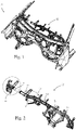
- FIG. 1 schematically showing a perspective front view of a structural assembly here in form of a vehicle BIW (body in White) 10 including a structural member 12 according to one possible embodiment of the invention here in form of lateral extending cross member.
- Structural member 12 may be located in the region of the vehicle's body illustrated in Fig. 1 and/or in other regions of the vehicle's body.
- Structural member 12 in its formation here as a cross member may also possibly be referred to and/or take form of: a cockpit cross-car beam, a front-end carrier (or the like); and may be used for supporting and/or connecting to vehicle bodywork components such as: an instrument panel, a steering column bracket, HVAC modules, airbags, headlight modules, windscreen wiper reservoirs (and the like).
- vehicle bodywork components such as: an instrument panel, a steering column bracket, HVAC modules, airbags, headlight modules, windscreen wiper reservoirs (and the like).
- structural member 12 may be seen as including along its extension a plurality of coupling regions 14.
- the coupling regions may be defined as areas along the structural member where coupling between a beam section 16 and a fitting 18 of the structural member takes place.
- such coupling between a beam section 16 and one example of a fitting 18 may be seen as including a nipping sleeve 20 that is molded over an area where the beam section 16 and fitting 18 meet and/or engage.
- Fitting 18 in its various forms includes a nipple 22 that may be arranged to fit into an open end of a beam section 16.
- the nipple may be formed on its outer periphery with one or more anchor regions 24, and in each given coupling region the nipping sleeve 20 can be used to press an area of the beam section that it overlies against the nipple of the fitting associated with the given coupling region.
- An anchoring region 24 may be defined as a localized region on the nipple's outer periphery with a geometry that is generally different to the geometry generally present in its surrounding.
- a generally cylindrical shaped nipple may be formed with an anchoring region on its outer cylindrical periphery that forms or includes a local area where the nipple's general cylindrical shape is not present.
- fitting 18 may include one of more brackets 26 for connecting/coupling to other entities, such as in the example of a structural member that is a cross member - to the shell of the vehicle's body and/or to vehicle bodywork components such as: an instrument panel, a steering wheel, heating and ventilation modules, airbags, headlight modules, windscreen wiper reservoirs (and the like).
- a structural member that is a cross member - to the shell of the vehicle's body and/or to vehicle bodywork components
- vehicle bodywork components such as: an instrument panel, a steering wheel, heating and ventilation modules, airbags, headlight modules, windscreen wiper reservoirs (and the like).
- Fittings according to at least certain embodiments of the present invention may be located at an end of another beam section - and thus coupling at a coupling region may result in coupling between two (or more) beam sections of a structural member (see examples in the structural assemblies of Figs. 9A to 9D ).
- Beam section 16 may be formed or may include thermoplastic material.
- beam section 16 may be formed from composite material such as continuous fiber-reinforced thermoplastics (e.g. organo sheets laminated glass/carbon fabrics or UD tape - laminated Unidirectional glass/carbon fibers or the like). Beam section 16 when exposed to pressurized injection molding of nipping sleeve 20 thereupon may be urged to at least partially deform and/or press against and/or abut nipple 22.
- Fitting 18 and/or nipple 22 may be formed from a variety of materials including (but not limited to) aluminum, magnesium, thermoplastic and thermosets, structural plastics (such as PP GF, PA GF, PA CF, PPS GF, POM GF, PBT GF, Epoxy, Polyester, and the like). Fitting 18 and/or nipple 22 thus may be formed from a variety of materials that can provide sufficient support/stiffness (counter force) against pressures applied during the joining phase due to pressure applied during the over-molding of nipping sleeve 20 upon nipple 22 with beam section 16 therebetween. Such provision of sufficient support/stiffness (counter force) may be provided with or without supportive beams/structures e.g. internal supportive beams/structures (such as those indicated below by numeral 29 with respect to Figs. 4 )
- Materials suitable for forming nipping sleeve 20 may include (but are not limited to) thermoplastic resins, fibers reinforced resins, possibly PE, PP, PS, ABS, PA, and/or PBT, and/or more preferably PP GF, PA GF, PA CF, PPS GF (etc.).
- Materials suitable for forming nipping sleeve 20 may also or alternatively be defined as being such that permit application of in-cavity pressures suitable for proper joining between nipping sleeve 20, beam section 16 and nipple 22. In a non-binding example, such suitable in-cavity pressures may be defined as above about 17 MPa and preferably above about 20 MPa.
- beam section 16 can be seen to have been deformed to closely follow the outer contour of nipple 22 including areas of the nipple including the anchor regions 24.
- Such abutting engagement formed by nipping sleeve 20 between the beam section 16 and the anchor regions on nipple 22, may be useful in assisting in resisting relative movements between the beam section and fitting, and/or in the fixing in place of beam section 16 relative to fitting 18 - during intended use of a structural member 12 including coupling regions 14 as discussed.
- such resistance to movements may be about a central axis X of the fitting's nipple.
- the optional planar shaped anchor regions 24 formed about axis X may act as abutting structures that can counter possible moment forces that may act to urge rotation or twisting between beam section 16 and nipple 22.
- Fig. 4B exemplifies possible resistance to movement generally along axis X formed e.g. by bulging and/or step-like formations located along or within the anchor regions 24 that can be used to resist forces acting to axially displace the beam section and fitting apart.
- Figs. 4A and 4B also illustrate possible provision of supportive beams/structures 29 for internally supporting nipple 22 against pressure applied during pressurized injection of nipping sleeve onto the nipple.
- Such optional beams/structures 29 if used may be defined as not extending axially beyond the location where nipping sleeve is designed to be injected - here marked by the dashed line 31.
- FIGs. 5A to 5C illustrating possible injection molding steps taken for creating a coupling region 14 along one possible embodiment of a structural member 12 of the invention.
- FIGs. 5A to 5C illustrating possible injection molding steps taken for creating a coupling region 14 along one possible embodiment of a structural member 12 of the invention.
- only one mold part 15 is shown revealing an interior side of the mold, and it is to be understood that one or more further mold part(s) may be used together with part 15 during injection molding.
- a prior fabricated fitting 18 and beam section 16 may be placed within a mold. Fitting 18 and beam section 16 may be placed one after the other or already fitted together within the mold. In this illustrated example, the fitting's nipple 22 and a portion of the beam section 16 fitted over the nipple are placed within a cavity 17 of the mold, which is arranged for receiving pressurized molten material for the forming of a nipping sleeve 20 thereupon.
- nipping sleeve 20 is illustrated being possibly formed with an optional integral bracket 26, suitable in the structural member for connecting to other entities such as in a cross member example to a shell of the vehicle's body and/or to vehicle bodywork components such as: an instrument panel, a steering wheel, heating and ventilation modules, airbags, headlight modules, windscreen wiper reservoirs (and the like).
- Nipping sleeve 20 formed by injected pressurized molten material is configured to deform and/or urge the beam section where it fits over the nipple to closely engage the nipple 22 and its anchoring regions 24. Formation of required forces for urging controlled deformation and/or close abutment of a beam section over a nipple, may be accomplished by various means.
- the nipping sleeve may be designed to have a suitable projection surface bearing against the beam section for forming required forces for creating the required deformation.
- the projection surface may be chosen to be substantially larger than other possible structures molded together with the nipping sleeve upon areas in the structural member.
- a gating point (see schematically illustrated by numeral 21 in Fig. 5C ) forming an opening where molten plastic material is injected into the nipping sleeve's cavity; may be chosen to be in proximity to the formed nipping sleeve so that pressure with the nipping sleeve's cavity is optimal, possibly maximal.
- the gating point (as illustrated) may be chosen to be at the nipping sleeve e.g. possibly identifiable on an outer exposed side/surface of the nipping sleeve.
- FIG. 6A illustrating an embodiment of a fitting 18 having an extension that follows an axis X, where in this example the extension is slightly curved.
- Fitting 18 of this embodiment includes a nipple 22 at each axial end and each nipple includes one or more anchoring regions 24 on its outer periphery.
- Fig. 6A At the upper side of Fig. 6A , fitting 18 and two beam sections 16 arranged to attach to respective nipples 22 at each one of its axial ends, are illustrated in an exploded un-attached state; and at the lower side of Fig. 6A , the beam sections 16 are shown fitted onto both axial ends of the fitting 18.
- the beam sections fitted on both axial ends of the fitting represents a state generally similar to that illustrated in Fig. 5B just before over-molding the nipping sleeve.
- the over molding of the nipping sleeves may be envisioned as e.g. being made within one single mold including two cavities one for the formation of each nipping sleeve.
- a mold may be used for over molding only one nipping sleeve onto one location where the beam section and nipple meet.
- Fig. 6B illustrates an imaginative view for illustration purposes only, showing an optional structure designed to be injected over areas of the connected fitting 18 and beam sections 16 of Fig. 6A .
- This structure as seen includes two nipping sleeves 20 (one for each merge of a nipple and a beam section), optional brackets 26 and optional struts 27 connecting between the nipping sleeves 20 and brackets 26 and possibly serving as supportive elements and/or channels for flow of molten material towards all areas of this optional molded structure.
- Fig. 6C provides a view of the fitting and beam sections of Fig. 6A with the optional structure seen in Fig. 6B molded thereupon.
- the molded nipping sleeves 20 accordingly serve for enhancing connection between each beam section 16 and its associated nipple 22 by deforming and/or urging each beam section 16 to closely follow the nipple's contour, inter alia, along its anchoring regions 24.
- Additional structures molded together with the nipping sleeves 20, such as the brackets 26, provide connecting regions to other possible entities, such as in a structural member being a cross member - to the shell of the vehicle's body and/or to vehicle bodywork components also in areas outside of the fitting such as on the beam section 16 itself.
- Cross-section B-B at the upper right-hand side of Fig. 6C illustrates the relative large projection surface S1 that nipping sleeve has upon beam section 16, which assists in obtaining effective/controlled deformation of the beam section upon nipple 22 and the anchoring regions 24 on the nipple.
- This relative large projection surface S1 can be seen in comparison e.g. to the relative small projection surface S2 that one of the optional struts 27 injected together with nipping sleeve 20 onto beam section 16 exhibits, which consequently results in smaller forces in such strut 27 being imposed upon the beam section and in turn in lower or substantial no deformation of the beam section in this area.
- Nipping sleeve 20 in at least certain embodiments, in comparison to other structures molded together with it onto a beam section 16; may be defined as having a substantially non-interrupted projection surface S1 that is substantially larger than other non-interrupted projection surfaces, such as projection surface S2 of strut 27.
- the nipping sleeve may be defined as extending between two axial ends (see ends 1, 2 marked in Fig. 4B ) and including an inner projection surface S1 that extends continuously and substantially un-interrupted between the axial ends 1, 2 - and which is arranged to bear against the beam section to press it against the fitting including areas in the fitting where the anchoring regions are present.
- Figs. 7A to 7E illustrating various fitting embodiments and various forms that the anchoring regions 24 may take.
- the anchoring regions take form of planar faces formed about the nipple generally similar to those illustrated in the former figures.
- Fig. 7B the anchoring regions take form of peripheral extending barb formations on the nipple.
- Fig. 7C the anchoring regions take form of indentations formed on the nipple.
- the fitting and nipple are shown possibly embodying a generally rectangle-like formation in a cross-section perpendicular to the fitting's axis (see, e.g., axis X in Figs. 4 of the fitting's nipple).
- the fitting of Fig. 7D includes anchoring regions 24, here optionally taking form of indentations with planar bottoms - however other type anchoring regions may also be possible - such as bulging formations (etc.).
- Fig. 7E exemplifies a fitting including more than two nipples, here three nipples each including anchoring regions. Such T-like formation of a fitting may be useful in connecting several beam sections, here three beam sections, together.
- FIGs. 8A and 8B illustrating a coupling region utilizing a fitting generally similar to that in Fig. 7D .
- the coupling region (similar to former discussed coupling regions) includes a nipping sleeve 20 that is molded over an area where a beam section 16 and the fitting 18 meet and/or engage.
- any other structural formation formed on the nipple upon which the beam section may be deformed may serve as a suitable anchoring region.
- the nipples and anchoring regions illustrated e.g. in Figs. 7A to 7E may be included in fittings that have other form to the one illustrated in these figures.
- FIGs. 9A to 9D illustrating various structural assemblies that may include various embodiments structural members and/or coupling regions here discussed.
- Fig. 9A illustrates a structural assembly 101 in formation of a roof rack arranged to be fitted onto a roof top of a vehicle.
- Structural assembly 101 includes coupling regions 141 connecting between beam sections 161 to form structural members of the assembly.
- the structural assembly 102 in Fig. 9B is in formation of a hand rail here fitted along a staircase - with again beam sections 162 and coupling regions 142 being shown connecting to each other to form structural members of assembly 102.
- Fig. 9C illustrates a structural assembly 103 in formation of a street workout structure - again including coupling regions 143 connecting between beam sections 163 to form structural members of the assembly.
- Fig. 9D illustrates a structural assembly 104 in formation of a ladder - again including coupling regions 144 connecting between beam sections 164 to form structural members of the assembly.
- each of the verbs, "comprise” “include” and “have”, and conjugates thereof, are used to indicate that the object or objects of the verb are not necessarily a complete listing of members, components, elements or parts of the subject or subjects of the verb.
Landscapes
- Engineering & Computer Science (AREA)
- Mechanical Engineering (AREA)
- General Engineering & Computer Science (AREA)
- Manufacturing & Machinery (AREA)
- Architecture (AREA)
- Chemical & Material Sciences (AREA)
- Combustion & Propulsion (AREA)
- Transportation (AREA)
- Civil Engineering (AREA)
- Structural Engineering (AREA)
- Body Structure For Vehicles (AREA)
- Joining Of Building Structures In Genera (AREA)
Applications Claiming Priority (2)
| Application Number | Priority Date | Filing Date | Title |
|---|---|---|---|
| US201862634837P | 2018-02-24 | 2018-02-24 | |
| PCT/IB2019/050763 WO2019162780A1 (en) | 2018-02-24 | 2019-01-30 | Structural member and/or coupling arrangement and/or method for same |
Publications (2)
| Publication Number | Publication Date |
|---|---|
| EP3755517A1 EP3755517A1 (en) | 2020-12-30 |
| EP3755517B1 true EP3755517B1 (en) | 2022-12-21 |
Family
ID=65718053
Family Applications (1)
| Application Number | Title | Priority Date | Filing Date |
|---|---|---|---|
| EP19709779.3A Active EP3755517B1 (en) | 2018-02-24 | 2019-01-30 | Structural member and/or coupling arrangement and/or method for same |
Country Status (5)
| Country | Link |
|---|---|
| US (1) | US10995785B2 (he) |
| EP (1) | EP3755517B1 (he) |
| CN (1) | CN111770826B (he) |
| IL (1) | IL276858B2 (he) |
| WO (1) | WO2019162780A1 (he) |
Families Citing this family (1)
| Publication number | Priority date | Publication date | Assignee | Title |
|---|---|---|---|---|
| CN112497699B (zh) * | 2020-10-30 | 2022-08-19 | 西安近代化学研究所 | 一种燃烧室筒段-封头绝热层一体化挤注成型系统及方法 |
Family Cites Families (12)
| Publication number | Priority date | Publication date | Assignee | Title |
|---|---|---|---|---|
| SE512411C2 (sv) * | 1998-08-11 | 2000-03-13 | Aba Sweden Ab | Anordning för hopkoppling av två styva rörformiga föremål |
| CN2443220Y (zh) * | 2000-10-18 | 2001-08-15 | 冯天裕 | 接头组件 |
| US7128360B2 (en) | 2002-12-10 | 2006-10-31 | Delphi Technologies, Inc. | Structural hybrid attachment system and method |
| US20070056748A1 (en) | 2003-10-17 | 2007-03-15 | Behr Gmbh & Co. Kg | Component for a motor vehicle |
| AT501051B8 (de) * | 2005-04-26 | 2007-02-15 | Ke Kelit Kunststoffwerk Gmbh | Anschlussvorrichtung für ein kunststoffrohr |
| CN100337003C (zh) * | 2005-12-22 | 2007-09-12 | 成志全 | 插扣卡型多功能脚手架 |
| US20100001552A1 (en) | 2008-07-01 | 2010-01-07 | Hyundai Motor Company | Mounting structure for cowl crossbar |
| WO2013148959A1 (en) * | 2012-03-30 | 2013-10-03 | Magna International Inc. | Plastic overmolding of aluminum extrusions |
| FR3014817B1 (fr) | 2013-12-18 | 2016-02-05 | Peugeot Citroen Automobiles Sa | Traverse pour planche de bord avec support lateral a structure mixte metallo-plastique |
| DE102014004158A1 (de) | 2014-03-17 | 2015-09-17 | Technische Universität Dresden | Verfahren zur Herstellung von Strukturelementen aus Lasteinleitungselement und Faser-Kunststoff-Verbund-Hohlprofil und Strukturelemente |
| DE102015213223A1 (de) * | 2015-07-15 | 2017-01-19 | Contitech Mgw Gmbh | Kupplungsarmatur für Rohrleitungen |
| CN206319575U (zh) * | 2016-12-06 | 2017-07-11 | 武汉理工大学 | 一种支架用连接装置 |
-
2019
- 2019-01-30 WO PCT/IB2019/050763 patent/WO2019162780A1/en active Application Filing
- 2019-01-30 EP EP19709779.3A patent/EP3755517B1/en active Active
- 2019-01-30 IL IL276858A patent/IL276858B2/he unknown
- 2019-01-30 US US16/975,126 patent/US10995785B2/en active Active
- 2019-01-30 CN CN201980014838.7A patent/CN111770826B/zh active Active
Also Published As
| Publication number | Publication date |
|---|---|
| EP3755517A1 (en) | 2020-12-30 |
| IL276858B1 (he) | 2023-07-01 |
| CN111770826B (zh) | 2021-12-21 |
| CN111770826A (zh) | 2020-10-13 |
| WO2019162780A1 (en) | 2019-08-29 |
| US20210003157A1 (en) | 2021-01-07 |
| IL276858B2 (he) | 2023-11-01 |
| IL276858A (he) | 2020-10-29 |
| US10995785B2 (en) | 2021-05-04 |
Similar Documents
| Publication | Publication Date | Title |
|---|---|---|
| CN110282021B (zh) | 车辆框架结构 | |
| US6296301B1 (en) | Motor vehicle body structure using a woven fiber | |
| US9914490B2 (en) | Frame structure with at least one console for connecting further components, method for producing and motor vehicle body | |
| EP1194327B1 (de) | Frontendmodul für ein kraftfahrzeug | |
| US6824199B2 (en) | Fender arrangement for a motor vehicle | |
| US7251915B2 (en) | Frame system for motor vehicle | |
| US6811195B2 (en) | Composite structural article for frame structures | |
| US20020060476A1 (en) | Overmoulded reinforced metal/plastic composite front panel for motor vehicle | |
| DE10022360A1 (de) | Profilverbundbauteil und Verfahren zu seiner Herstellung | |
| CN102905961B (zh) | 结构构件 | |
| US5853857A (en) | Windshield frame | |
| JP2005511308A5 (he) | ||
| CN104781060A (zh) | 横梁结构及其制造方法 | |
| US20170120956A1 (en) | Crosspiece for vehicle | |
| EP2853450B1 (en) | Instrument cluster finish panel | |
| US20190210662A1 (en) | Structural part of a body in white of a vehicle and associated manufacturing method | |
| US20200307708A1 (en) | Vehicle Structural Component and Method for Producing a Vehicle Structural Component | |
| US20190329823A1 (en) | Chassis for a vehicle | |
| EP3755517B1 (en) | Structural member and/or coupling arrangement and/or method for same | |
| EP2948362B1 (de) | Trägerstruktur und verfahren zum herstellen einer trägerstruktur | |
| JP7218596B2 (ja) | 繊維強化樹脂構造体の縁部構造 | |
| CN108068895B (zh) | 机动车辆车架的一体部件 | |
| EP0685386A1 (en) | Adapter fitting for the selective connection of a radiator to a one- or a two pipe system | |
| CN114475786A (zh) | 车身结合结构 | |
| US11358651B2 (en) | Structural component |
Legal Events
| Date | Code | Title | Description |
|---|---|---|---|
| STAA | Information on the status of an ep patent application or granted ep patent |
Free format text: STATUS: UNKNOWN |
|
| STAA | Information on the status of an ep patent application or granted ep patent |
Free format text: STATUS: THE INTERNATIONAL PUBLICATION HAS BEEN MADE |
|
| PUAI | Public reference made under article 153(3) epc to a published international application that has entered the european phase |
Free format text: ORIGINAL CODE: 0009012 |
|
| STAA | Information on the status of an ep patent application or granted ep patent |
Free format text: STATUS: REQUEST FOR EXAMINATION WAS MADE |
|
| 17P | Request for examination filed |
Effective date: 20200924 |
|
| AK | Designated contracting states |
Kind code of ref document: A1 Designated state(s): AL AT BE BG CH CY CZ DE DK EE ES FI FR GB GR HR HU IE IS IT LI LT LU LV MC MK MT NL NO PL PT RO RS SE SI SK SM TR |
|
| AX | Request for extension of the european patent |
Extension state: BA ME |
|
| STAA | Information on the status of an ep patent application or granted ep patent |
Free format text: STATUS: EXAMINATION IS IN PROGRESS |
|
| STAA | Information on the status of an ep patent application or granted ep patent |
Free format text: STATUS: EXAMINATION IS IN PROGRESS |
|
| 17Q | First examination report despatched |
Effective date: 20210120 |
|
| DAV | Request for validation of the european patent (deleted) | ||
| DAX | Request for extension of the european patent (deleted) | ||
| GRAP | Despatch of communication of intention to grant a patent |
Free format text: ORIGINAL CODE: EPIDOSNIGR1 |
|
| STAA | Information on the status of an ep patent application or granted ep patent |
Free format text: STATUS: GRANT OF PATENT IS INTENDED |
|
| INTG | Intention to grant announced |
Effective date: 20210628 |
|
| GRAJ | Information related to disapproval of communication of intention to grant by the applicant or resumption of examination proceedings by the epo deleted |
Free format text: ORIGINAL CODE: EPIDOSDIGR1 |
|
| STAA | Information on the status of an ep patent application or granted ep patent |
Free format text: STATUS: EXAMINATION IS IN PROGRESS |
|
| INTC | Intention to grant announced (deleted) | ||
| GRAP | Despatch of communication of intention to grant a patent |
Free format text: ORIGINAL CODE: EPIDOSNIGR1 |
|
| STAA | Information on the status of an ep patent application or granted ep patent |
Free format text: STATUS: GRANT OF PATENT IS INTENDED |
|
| INTG | Intention to grant announced |
Effective date: 20220701 |
|
| GRAS | Grant fee paid |
Free format text: ORIGINAL CODE: EPIDOSNIGR3 |
|
| GRAA | (expected) grant |
Free format text: ORIGINAL CODE: 0009210 |
|
| STAA | Information on the status of an ep patent application or granted ep patent |
Free format text: STATUS: THE PATENT HAS BEEN GRANTED |
|
| AK | Designated contracting states |
Kind code of ref document: B1 Designated state(s): AL AT BE BG CH CY CZ DE DK EE ES FI FR GB GR HR HU IE IS IT LI LT LU LV MC MK MT NL NO PL PT RO RS SE SI SK SM TR |
|
| REG | Reference to a national code |
Ref country code: GB Ref legal event code: FG4D |
|
| REG | Reference to a national code |
Ref country code: CH Ref legal event code: EP |
|
| REG | Reference to a national code |
Ref country code: DE Ref legal event code: R096 Ref document number: 602019023382 Country of ref document: DE |
|
| REG | Reference to a national code |
Ref country code: AT Ref legal event code: REF Ref document number: 1538779 Country of ref document: AT Kind code of ref document: T Effective date: 20230115 |
|
| REG | Reference to a national code |
Ref country code: IE Ref legal event code: FG4D |
|
| REG | Reference to a national code |
Ref country code: LT Ref legal event code: MG9D |
|
| REG | Reference to a national code |
Ref country code: NL Ref legal event code: MP Effective date: 20221221 |
|
| PG25 | Lapsed in a contracting state [announced via postgrant information from national office to epo] |
Ref country code: SE Free format text: LAPSE BECAUSE OF FAILURE TO SUBMIT A TRANSLATION OF THE DESCRIPTION OR TO PAY THE FEE WITHIN THE PRESCRIBED TIME-LIMIT Effective date: 20221221 Ref country code: NO Free format text: LAPSE BECAUSE OF FAILURE TO SUBMIT A TRANSLATION OF THE DESCRIPTION OR TO PAY THE FEE WITHIN THE PRESCRIBED TIME-LIMIT Effective date: 20230321 Ref country code: LT Free format text: LAPSE BECAUSE OF FAILURE TO SUBMIT A TRANSLATION OF THE DESCRIPTION OR TO PAY THE FEE WITHIN THE PRESCRIBED TIME-LIMIT Effective date: 20221221 Ref country code: FI Free format text: LAPSE BECAUSE OF FAILURE TO SUBMIT A TRANSLATION OF THE DESCRIPTION OR TO PAY THE FEE WITHIN THE PRESCRIBED TIME-LIMIT Effective date: 20221221 |
|
| REG | Reference to a national code |
Ref country code: AT Ref legal event code: MK05 Ref document number: 1538779 Country of ref document: AT Kind code of ref document: T Effective date: 20221221 |
|
| PG25 | Lapsed in a contracting state [announced via postgrant information from national office to epo] |
Ref country code: RS Free format text: LAPSE BECAUSE OF FAILURE TO SUBMIT A TRANSLATION OF THE DESCRIPTION OR TO PAY THE FEE WITHIN THE PRESCRIBED TIME-LIMIT Effective date: 20221221 Ref country code: LV Free format text: LAPSE BECAUSE OF FAILURE TO SUBMIT A TRANSLATION OF THE DESCRIPTION OR TO PAY THE FEE WITHIN THE PRESCRIBED TIME-LIMIT Effective date: 20221221 Ref country code: HR Free format text: LAPSE BECAUSE OF FAILURE TO SUBMIT A TRANSLATION OF THE DESCRIPTION OR TO PAY THE FEE WITHIN THE PRESCRIBED TIME-LIMIT Effective date: 20221221 Ref country code: GR Free format text: LAPSE BECAUSE OF FAILURE TO SUBMIT A TRANSLATION OF THE DESCRIPTION OR TO PAY THE FEE WITHIN THE PRESCRIBED TIME-LIMIT Effective date: 20230322 |
|
| PG25 | Lapsed in a contracting state [announced via postgrant information from national office to epo] |
Ref country code: NL Free format text: LAPSE BECAUSE OF FAILURE TO SUBMIT A TRANSLATION OF THE DESCRIPTION OR TO PAY THE FEE WITHIN THE PRESCRIBED TIME-LIMIT Effective date: 20221221 |
|
| PG25 | Lapsed in a contracting state [announced via postgrant information from national office to epo] |
Ref country code: SM Free format text: LAPSE BECAUSE OF FAILURE TO SUBMIT A TRANSLATION OF THE DESCRIPTION OR TO PAY THE FEE WITHIN THE PRESCRIBED TIME-LIMIT Effective date: 20221221 Ref country code: RO Free format text: LAPSE BECAUSE OF FAILURE TO SUBMIT A TRANSLATION OF THE DESCRIPTION OR TO PAY THE FEE WITHIN THE PRESCRIBED TIME-LIMIT Effective date: 20221221 Ref country code: PT Free format text: LAPSE BECAUSE OF FAILURE TO SUBMIT A TRANSLATION OF THE DESCRIPTION OR TO PAY THE FEE WITHIN THE PRESCRIBED TIME-LIMIT Effective date: 20230421 Ref country code: ES Free format text: LAPSE BECAUSE OF FAILURE TO SUBMIT A TRANSLATION OF THE DESCRIPTION OR TO PAY THE FEE WITHIN THE PRESCRIBED TIME-LIMIT Effective date: 20221221 Ref country code: EE Free format text: LAPSE BECAUSE OF FAILURE TO SUBMIT A TRANSLATION OF THE DESCRIPTION OR TO PAY THE FEE WITHIN THE PRESCRIBED TIME-LIMIT Effective date: 20221221 Ref country code: CZ Free format text: LAPSE BECAUSE OF FAILURE TO SUBMIT A TRANSLATION OF THE DESCRIPTION OR TO PAY THE FEE WITHIN THE PRESCRIBED TIME-LIMIT Effective date: 20221221 Ref country code: AT Free format text: LAPSE BECAUSE OF FAILURE TO SUBMIT A TRANSLATION OF THE DESCRIPTION OR TO PAY THE FEE WITHIN THE PRESCRIBED TIME-LIMIT Effective date: 20221221 |
|
| PG25 | Lapsed in a contracting state [announced via postgrant information from national office to epo] |
Ref country code: SK Free format text: LAPSE BECAUSE OF FAILURE TO SUBMIT A TRANSLATION OF THE DESCRIPTION OR TO PAY THE FEE WITHIN THE PRESCRIBED TIME-LIMIT Effective date: 20221221 Ref country code: PL Free format text: LAPSE BECAUSE OF FAILURE TO SUBMIT A TRANSLATION OF THE DESCRIPTION OR TO PAY THE FEE WITHIN THE PRESCRIBED TIME-LIMIT Effective date: 20221221 Ref country code: IS Free format text: LAPSE BECAUSE OF FAILURE TO SUBMIT A TRANSLATION OF THE DESCRIPTION OR TO PAY THE FEE WITHIN THE PRESCRIBED TIME-LIMIT Effective date: 20230421 Ref country code: AL Free format text: LAPSE BECAUSE OF FAILURE TO SUBMIT A TRANSLATION OF THE DESCRIPTION OR TO PAY THE FEE WITHIN THE PRESCRIBED TIME-LIMIT Effective date: 20221221 |
|
| REG | Reference to a national code |
Ref country code: CH Ref legal event code: PL |
|
| REG | Reference to a national code |
Ref country code: DE Ref legal event code: R097 Ref document number: 602019023382 Country of ref document: DE |
|
| PG25 | Lapsed in a contracting state [announced via postgrant information from national office to epo] |
Ref country code: MC Free format text: LAPSE BECAUSE OF FAILURE TO SUBMIT A TRANSLATION OF THE DESCRIPTION OR TO PAY THE FEE WITHIN THE PRESCRIBED TIME-LIMIT Effective date: 20221221 Ref country code: LU Free format text: LAPSE BECAUSE OF NON-PAYMENT OF DUE FEES Effective date: 20230130 |
|
| REG | Reference to a national code |
Ref country code: BE Ref legal event code: MM Effective date: 20230131 |
|
| PLBE | No opposition filed within time limit |
Free format text: ORIGINAL CODE: 0009261 |
|
| STAA | Information on the status of an ep patent application or granted ep patent |
Free format text: STATUS: NO OPPOSITION FILED WITHIN TIME LIMIT |
|
| PG25 | Lapsed in a contracting state [announced via postgrant information from national office to epo] |
Ref country code: LI Free format text: LAPSE BECAUSE OF NON-PAYMENT OF DUE FEES Effective date: 20230131 Ref country code: DK Free format text: LAPSE BECAUSE OF FAILURE TO SUBMIT A TRANSLATION OF THE DESCRIPTION OR TO PAY THE FEE WITHIN THE PRESCRIBED TIME-LIMIT Effective date: 20221221 Ref country code: CH Free format text: LAPSE BECAUSE OF NON-PAYMENT OF DUE FEES Effective date: 20230131 |
|
| 26N | No opposition filed |
Effective date: 20230922 |
|
| GBPC | Gb: european patent ceased through non-payment of renewal fee |
Effective date: 20230321 |
|
| PG25 | Lapsed in a contracting state [announced via postgrant information from national office to epo] |
Ref country code: BE Free format text: LAPSE BECAUSE OF NON-PAYMENT OF DUE FEES Effective date: 20230131 |
|
| PG25 | Lapsed in a contracting state [announced via postgrant information from national office to epo] |
Ref country code: GB Free format text: LAPSE BECAUSE OF NON-PAYMENT OF DUE FEES Effective date: 20230321 |
|
| PG25 | Lapsed in a contracting state [announced via postgrant information from national office to epo] |
Ref country code: SI Free format text: LAPSE BECAUSE OF FAILURE TO SUBMIT A TRANSLATION OF THE DESCRIPTION OR TO PAY THE FEE WITHIN THE PRESCRIBED TIME-LIMIT Effective date: 20221221 Ref country code: IE Free format text: LAPSE BECAUSE OF NON-PAYMENT OF DUE FEES Effective date: 20230130 Ref country code: GB Free format text: LAPSE BECAUSE OF NON-PAYMENT OF DUE FEES Effective date: 20230321 Ref country code: FR Free format text: LAPSE BECAUSE OF NON-PAYMENT OF DUE FEES Effective date: 20230221 |
|
| PGFP | Annual fee paid to national office [announced via postgrant information from national office to epo] |
Ref country code: DE Payment date: 20240119 Year of fee payment: 6 |