EP3754815A1 - Stator unit and electric valve provided with same - Google Patents
Stator unit and electric valve provided with same Download PDFInfo
- Publication number
- EP3754815A1 EP3754815A1 EP19754940.5A EP19754940A EP3754815A1 EP 3754815 A1 EP3754815 A1 EP 3754815A1 EP 19754940 A EP19754940 A EP 19754940A EP 3754815 A1 EP3754815 A1 EP 3754815A1
- Authority
- EP
- European Patent Office
- Prior art keywords
- yoke
- stator
- rotation
- plate portion
- stopping member
- Prior art date
- Legal status (The legal status is an assumption and is not a legal conclusion. Google has not performed a legal analysis and makes no representation as to the accuracy of the status listed.)
- Granted
Links
Images



Classifications
-
- H—ELECTRICITY
- H02—GENERATION; CONVERSION OR DISTRIBUTION OF ELECTRIC POWER
- H02K—DYNAMO-ELECTRIC MACHINES
- H02K5/00—Casings; Enclosures; Supports
- H02K5/04—Casings or enclosures characterised by the shape, form or construction thereof
- H02K5/12—Casings or enclosures characterised by the shape, form or construction thereof specially adapted for operating in liquid or gas
- H02K5/128—Casings or enclosures characterised by the shape, form or construction thereof specially adapted for operating in liquid or gas using air-gap sleeves or air-gap discs
-
- F—MECHANICAL ENGINEERING; LIGHTING; HEATING; WEAPONS; BLASTING
- F16—ENGINEERING ELEMENTS AND UNITS; GENERAL MEASURES FOR PRODUCING AND MAINTAINING EFFECTIVE FUNCTIONING OF MACHINES OR INSTALLATIONS; THERMAL INSULATION IN GENERAL
- F16K—VALVES; TAPS; COCKS; ACTUATING-FLOATS; DEVICES FOR VENTING OR AERATING
- F16K27/00—Construction of housing; Use of materials therefor
-
- F—MECHANICAL ENGINEERING; LIGHTING; HEATING; WEAPONS; BLASTING
- F16—ENGINEERING ELEMENTS AND UNITS; GENERAL MEASURES FOR PRODUCING AND MAINTAINING EFFECTIVE FUNCTIONING OF MACHINES OR INSTALLATIONS; THERMAL INSULATION IN GENERAL
- F16K—VALVES; TAPS; COCKS; ACTUATING-FLOATS; DEVICES FOR VENTING OR AERATING
- F16K31/00—Actuating devices; Operating means; Releasing devices
- F16K31/02—Actuating devices; Operating means; Releasing devices electric; magnetic
- F16K31/04—Actuating devices; Operating means; Releasing devices electric; magnetic using a motor
-
- H—ELECTRICITY
- H02—GENERATION; CONVERSION OR DISTRIBUTION OF ELECTRIC POWER
- H02K—DYNAMO-ELECTRIC MACHINES
- H02K21/00—Synchronous motors having permanent magnets; Synchronous generators having permanent magnets
- H02K21/12—Synchronous motors having permanent magnets; Synchronous generators having permanent magnets with stationary armatures and rotating magnets
- H02K21/14—Synchronous motors having permanent magnets; Synchronous generators having permanent magnets with stationary armatures and rotating magnets with magnets rotating within the armatures
- H02K21/145—Synchronous motors having permanent magnets; Synchronous generators having permanent magnets with stationary armatures and rotating magnets with magnets rotating within the armatures having an annular armature coil
Definitions
- the present disclosure relates to a stator unit, in particular, a casting-type stator unit in which resin having low hardness, such as a urethane resin, is used as a mold resin, and to a motor-driven valve including the same.
- resin having low hardness such as a urethane resin
- FIG. 9 An exemplary conventional stator unit along with a motor-driven valve using the same is illustrated in Fig. 9 , and the configuration will be briefly described (see Patent Literature 1 for the structure in detail).
- a lower end portion of a cylindrical can 120 with a ceiling portion is hermetically joined, through welding or the like, to a valve body 110 having a pipe joint 111 as a lateral inlet/outlet and a pipe joint 112 as a downward inlet/outlet.
- a rotor (not shown) is disposed on the inner periphery of the can 120 with a predetermined gap therebetween, and a stator unit 50 is externally and securely fitted to the can 120 so as to rotary drive the rotor.
- the rotor and the stator unit 50 constitute a stepping motor.
- the stator unit 50 includes stator coils 50A and 50B in two phases (phase A and phase B).
- the stator coil 50A on an upper stage has a pair of upper and lower yokes 51 and 52, a bobbin 55 attached to the yokes 51 and 52, a coil 56 wound around the bobbin 55, and the like.
- the stator coil 50B on a lower stage which is configured in such a manner as being vertically inverted from the configuration of the stator coil 50A on the upper stage, has the pair of upper and lower yokes 52 and 51, the bobbin 55 attached to the yokes 52 and 51, the coil 56 wound around the bobbin 55, and the like.
- the yokes 51 and 52 are made of magnetic material as raw material, and the inner periphery side of each of the yokes 51 and 52 is provided with elongated claw-shaped or isosceles triangular magnetic-pole teeth 58 at a predetermined angular interval (for example, at an interval of 30°).
- the stator unit 50 is molded using a thermoplastic resin, such as an ABS resin, as a mold resin 59.
- the stator coils 50A and 50B that are stacked are set in a mold for molding.
- the mold for molding includes, for example, a lower die in which the stacked stator coils 50A and 50B are to be placed, a core for forming a fit-insertion hole 61 into which the can 120 is to be fit-inserted, and an upper die to cover the lower die so as to form a hermetically sealed space in cooperation with the lower die and the core.
- stator coils 50A and 50B are set inside the mold configured as such and a thermoplastic resin as the mold resin 59 is melted and then injected into the mold, the outer periphery of the stator coils 50A and 50B is covered with and their internal gaps are filled with the mold resin 59. Then, when the mold resin 59 is hardened, the outer side of the stator coils 50A and 50B (the outer periphery and upper and lower portions thereof) is sealed.
- the lead wire connecting portion 70 is provided with a base 73 and a connector 74 for connecting a plurality of coil terminal pins 72 and a plurality of lead wires 75, and has attached thereto a cover 76 that covers the upper portion of the coil terminal pins 72, base 73, connector 74, lead wires 75, and the like, the inside of the cover 76 being filled with a resin 77 of a silicone resin, an epoxy resin, or the like, and sealed.
- a ring-like rotation-stopping member 30 is securely attached so as to prevent the relative rotation and relative movement among the stator unit 50, the can 120, and the valve body 110.
- the rotation-stopping member 30 which is produced through die-cutting and press working of a conductive metal plate, such as SUS, includes an annular flat plate portion 31 with an opening 32 through which the can 120 can be inserted.
- a conductive metal plate such as SUS
- the annular flat plate portion 31 On the underside of the mold resin 59 of the stator body 60, a plurality of bar-like portions projecting downward is provided, and the annular flat plate portion 31 has round holes 33 through which the bar-like portions can be inserted.
- a plurality of engagement plate portions 35 each having an inverted L-shape, is cut and raised, engagement pieces 37 facing downward of the engagement plate portions 35 each have a round or elongated hole-shaped engagement hole 38 formed therein, and the can 120 has semispherical projections 122 formed in its circumferential direction, each semispherical projection 122 being fitted into the engagement hole 38.
- the rotation-stopping member 30 is securely attached to the stator unit 50 in the aforementioned manner, the stator unit 50 is externally fitted to the can 120, and the projections 122 formed in the can 120 are fitted into their respective engagement holes 38 formed in the engagement pieces 37 facing downward of the engagement plate portions 35, so that the engagement pieces 37 are outwardly distorted to allow, with their spring force, the projections 122 to firmly fit into the engagement holes 38.
- the stator unit 50 is externally and securely fitted to the can 120, so that their relative rotation and relative movement are prevented.
- a conducting spring 40 having conductivity is interposed between the magnetic-pole teeth 58 of the yoke 51 positioned at the lowest and the rotation-stopping member 30.
- the yokes 51 and 52 and the can 120 are at the same potential, which can prevent undesirable discharge that may be generated between the yokes 51 and 52, and the can 120, thereby enabling to reduce adverse effects on the peripheral circuits.
- a bifurcated one as shown in Patent Literature 2 is also known, which is attached to one side of the stator body, having a pair of circular sandwiching portions adapted to sandwich a pipe joint as a lateral inlet/outlet so as to prevent the relative rotation and relative movement between the stator unit 50 and the can 120.
- thermoplastic resin such as an ABS resin
- a thermoplastic resin, such as an ABS resin for use in molding becomes relatively solid when hardened, and thus, is inflexible to thermal deformation due to varying temperature, thereby likely causing cracks, distortion, and the like. Therefore, the improvement in the durability, product life, and the like has been sought.
- thermosetting resin having low hardness such as a urethane resin
- thermosetting resin having low hardness such as a urethane resin
- the bar-like portions 64 or the like for fixing the rotation-stopping member 30 to the stator body 60 become fragile, which likely leads to improper positioning of the stator coils 50A and 50B as well as fails to firmly fix the rotation-stopping member 30 to the stator body 60.
- the mold resin is a thermosetting resin, a fixation method through the post-process, such as ultrasonic welding or thermal swaging, cannot be adopted.
- the mold resin 59 of the stator unit 50 and the resin 77 of the lead wire connecting portion 70 illustrated in Fig. 9 are formed as a mold resin 19 made of a thermosetting resin having low hardness, such as a urethane resin, and a portion sealed with the mold resin 19 is formed as a stator body 20.
- the outer periphery surface of the stator body 20, except for its underside, is covered with a cover 57 made of a thermoplastic resin, such as an ABS.
- each seating 41 in a stepped short columnar shape being made of conductive metal, such as SUS.
- the rotation-stopping member 30 with the seatings 41 has substantially the same configuration as that of the rotation-stopping member 30 illustrated in Fig. 9 , except for the seatings 41.
- the annular flat plate portion 31 of the rotation-stopping member 30 has a plurality of round holes 33 (eight round holes formed at an interval of 45° in the illustrated example), and a small-diameter portion of each seating 41 in a stepped short columnar shape is fitted into and joined through welding to each round hole 33 (each of every other round holes 33 of eight round holes 33 (at an interval of 90°), that is, four round holes 33 in the illustrated example) (a welded portion K1), prior to the assembling of the stator coils 50A and 50B.
- each seating 41 is joined to the underside of the yoke 51 positioned at the lowest through resistance welding (a welded portion K2), prior to the assembling of the stator coils 50A and 50B.
- stator coils 50A and 50B are assembled, the assembled stator coils 50A and 50B are vertically stacked and set inside a mold in which the cover 57 is placed in advance, and a thermosetting resin having low hardness, such as a urethane resin, as the mold resin, is injected into the mold through vacuum casting and then hardened in a drying furnace.
- a thermosetting resin having low hardness such as a urethane resin
- stator coils 50A and 50B are demolded, and the stator unit 90 is obtained, in which portions including the surroundings of the seatings 41 of the rotation-stopping member 30 are covered and filled with the mold resin 19 of a thermosetting resin having low hardness, such as a urethane resin, and sealed.
- the rotation-stopping member 30 can be fixed to the stator body 20, and positioning of the stator coils 50A and 50B can also be relatively properly performed.
- the seatings 41 are made of conductive metal, such as SUS, similarly to the conducting spring 40 of the stator unit 50 illustrated in Fig. 9 , the yokes 51 and 52, the can 120, and the valve body 110 are electrically connected via the seatings 41 and the rotation-stopping member 30.
- the yokes 51 and 52 and the can 120 are at the same potential, which can prevent undesirable discharge that may be generated between the yokes 51 and 52, and the can 120, thereby enabling to reduce adverse effects on the peripheral circuits.
- the aforementioned conventional stator unit 90 requires the seatings 41 to be attached to the rotation-stopping member 30, and joining through welding of the seatings 41 and the rotation-stopping member 30 and of the seatings 41 and the yoke 51.
- This increases the number of components, and the man-hours of assembling due to the necessity of separate welding of the seatings 41 and the rotation-stopping member 30 and of the seatings 41 and the yoke 51.
- the contact area between the seatings 41, each having a short columnar shape, and the yoke 51 increases at the time of welding, the resistance welding is difficult to be performed, and sufficient strength of the welded portions may not be secured.
- the present disclosure has been made in view of the aforementioned circumstances, and provides a stator unit capable of reducing the number of components and man-hours of assembling so as to suppress the parts cost and production cost, and a motor-driven valve including the same.
- a stator unit basically includes a stator body having a stator coil with a yoke, a bobbin attached to the yoke, and a coil wound around the bobbin, an outer side of the stator coil being sealed with a mold resin, and a rotation-stopping member disposed adjacent to the yoke of the stator body, in which the rotation-stopping member has a base plate portion, an engagement piece for stopping rotation that is provided facing in a direction opposite to a side of the yoke from the base plate portion, and a projecting piece that is bent and raised toward the side of the yoke from the base plate portion, a tip end portion of the projecting piece being joined through welding to the yoke.
- the stator unit may basically include a stator body having a stator coil with a yoke, a bobbin attached to the yoke, and a coil wound around the bobbin, an outer side of the stator coil being sealed with a mold resin, and a rotation-stopping member disposed adjacent to the yoke of the stator body, in which the rotation-stopping member has an annular base plate portion, an engagement piece for stopping rotation that is provided facing in a direction opposite to a side of the yoke from the base plate portion, and a projecting piece that is bent and raised toward the side of the yoke from the base plate portion, a tip end portion of the projecting piece being joined through welding to the yoke.
- the rotation-stopping member may be embedded in the mold resin such that the engagement piece partially or entirely projects from the mold resin.
- the engagement piece may be provided in the engagement plate portion that is bent from the inner periphery side of the base plate portion in the direction opposite to the side of the yoke.
- the projecting piece may be cut and raised from a portion between the inner periphery and the outer periphery of the base plate portion toward the side of the yoke.
- the engagement piece may include three or more engagement pieces provided at an equiangular interval in a circumferential direction and the projecting piece may include three or more projecting pieces provided likewise.
- a urethane resin, a silicone resin, or an epoxy resin may be used as the mold resin.
- the rotation-stopping member may be made of a conductive metal plate.
- a motor-driven valve according to the present disclosure is characterized in that the aforementioned stator unit is externally and securely fitted to the can that is securely attached to the valve body.
- the rotation-stopping member since the rotation-stopping member is provided with the projecting piece that is bent and raised toward the side of the yoke, and the projecting piece is joined through welding to the yoke, the rotation-stopping member can be firmly fixed to the stator body, and positioning of the stator coil can also be relatively properly performed.
- the rotation-stopping member with the projecting pieces can be formed as a single component through, for example, die-cutting and press working, and thus can significantly reduce the number of components and also the number of welded portions (the number of times of welding) by half, so that parts cost and production cost can be reduced, as compared to the stator units as in the aforementioned conventional examples that use the rotation-stopping member with separate seatings.
- the contact area between the projecting pieces and the yoke at the time of welding is reduced, resistance welding is facilitated, so that sufficient strength of the welded portions can be secured.
- advantageous effects can be obtained that variations in the clearance between the yoke and the rotation-stopping member, that is, those in the positional relations among the stator coil, the can, the rotor, and the like can be reduced.
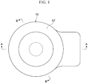
- Fig. 1 is a plan view of an embodiment of a stator unit according to the present disclosure
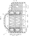
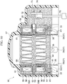
- Fig. 2 and Fig. 3 are cross-sectional views of Fig. 1 taken along arrow A-A and arrow B-B, respectively
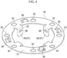
- Fig. 4 is an upper perspective view of a rotation-stopping member for use in the stator unit illustrated in Fig. 1 to Fig. 3
- Fig. 5 is a lower perspective view of a yoke and the rotation-stopping member joined through welding to the yoke illustrated in Fig. 2 and Fig. 3
- Fig. 6 to Fig. 8 are respectively an underside view, a right-side view (a reversed view of Fig. 6 taken along arrow C), and a cross-sectional view taken along arrow D1-D1 (a reversed cross-sectional view of Fig. 6 taken along arrow D2-D2) of Fig. 5 .
- a stator unit 10 of the present embodiment is externally and securely fitted to the can 120 that is securely attached to the valve body 110 of the motor-driven valve 100 as illustrated in Fig. 9 , and constitutes a stepping motor, together with a rotor (not shown) disposed inside the can 120.
- the stator unit 10 of the present embodiment includes the mold resin 19 made of a thermosetting resin having low hardness, such as a urethane resin, and a portion sealed with the mold resin 19 is formed as the stator body 20 (see Fig. 2 and Fig. 3 ).
- the outer periphery surface of the stator body 20, except for its underside, is covered with the cover 57 made of a thermoplastic resin, such as an ABS.
- a lower portion of the mold resin 19 of the stator body 20 is provided with the rotation-stopping member 30 made of a conductive metal plate so as to be embedded in the mold resin 19 such that the engagement pieces 37 facing downward of the engagement plate portions 35 provided on the inner periphery side each project partially or entirely from the mold resin 19.
- This rotation-stopping member 30 has substantially the same basic configuration as that of the rotation-stopping member 30 illustrated in Fig. 9 to Figs. 11A and 11B .
- the rotation-stopping member 30, which is produced through die-cutting and press working of a conductive metal plate, such as SUS, includes the annular flat plate portion (the annular base plate portion) 31 with the opening 32 through which the can 120 can be inserted, the annular flat plate portion 31 having eight round holes 33 in total formed at an interval of 45°.
- each engagement plate portion 35 On the side of the opening 32 (the inner periphery side) of the annular flat plate portion 31 of the rotation-stopping member 30, four engagement plate portions 35, each having an inverted L shape, are cut and raised (formed by bending) at an interval of 90°, and the engagement pieces 37 facing downward (in a direction opposite to the side of the adjacent yoke 51) of the engagement plate portions 35 each have formed therein a round or elongated hole-shaped engagement hole 38.
- each projecting piece 39 is formed so as to be cut and raised upward from a portion between the inner periphery and the outer periphery (more specifically, a substantially center portion in the radial direction) of the annular flat plate portion 31.
- the aforementioned eight round holes 33 and four engagement plate portions 35 are formed through die-cutting and press working, and the four projecting pieces 39 are formed through separate die-cutting and press working.
- the upper end faces (the tip end portions) of the four projecting pieces 39 which have an identical shape and are bent and raised upward from the annular flat plate portion 31, abut and are joined, through resistance welding, to an underside (an annular flat surface portion) 51d of the yoke 51 positioned at the lowest (a welded portion K3), prior to the assembling of the stator coils 50A and 50B.
- This joining through welding is performed such that the positioning of the rotation-stopping member 30 relative to the underside (the annular flat surface portion) 51d of the yoke 51 in the vertical and circumferential directions is performed using jigs or the like, so as to properly set the relative positional relation between the yoke 51 and the rotation-stopping member 30.
- stator coils 50A and 50B are assembled, the assembled stator coils 50A and 50B are vertically stacked and set inside a mold in which the cover 57 is placed in advance, and a thermosetting resin having low hardness, such as a urethane resin, as the mold resin, is injected into the mold through vacuum casting and then hardened in a drying furnace.
- a thermosetting resin having low hardness such as a urethane resin
- stator coils 50A and 50B are demolded, and the stator unit 10 is obtained, in which portions including the surroundings of the projecting pieces 39 of the rotation-stopping member 30 are covered and filled with the mold resin 19 of a thermosetting resin having low hardness, such as a urethane resin, and sealed.
- the stator unit 10 obtained as such is externally fitted to the can 120, and four projections 122 formed in the can 120 are fitted into their respective engagement holes 38 formed in the engagement pieces 37 facing downward of the four engagement plate portions 35, so that the engagement pieces 37 are outwardly distorted to allow, with their spring force, the projections 122 to firmly fit into the engagement holes 38.
- the stator unit 10 is externally and securely fitted to the can 120, so that their relative rotation and relative movement are prevented.
- the four projecting pieces 39 that are bent and raised toward the side of the yoke 51 are provided in the rotation-stopping member 30 and are joined through welding to the yoke 51, and thus, the rotation-stopping member 30 can be firmly fixed to the stator body 20, and also, the positioning of the stator coils 50A and 50B can be relatively properly performed.
- the rotation-stopping member 30 with the projecting pieces 39 can be formed as a single component through, for example, die-cutting and press working, and thus can significantly reduce the number of components and also the number of welded portions (the number of times of welding) by half, so that parts cost and production cost can be reduced, as compared to the stator units as in the aforementioned conventional examples that use the rotation-stopping member 30 with the separate seatings 41.
- the contact area between the projecting pieces 39 and the yoke 51 at the time of welding is reduced, resistance welding is facilitated, so that sufficient strength of the welded portions can be secured.
- the rotation-stopping member 30 including the four projecting pieces 39 is made of conductive metal, such as SUS, and thus, similarly to the stator units 50 and 90 illustrated in Fig. 9 to Figs. 11A and 11B , the yokes 51 and 52, the can 120, and the valve body 110 are electrically connected via the rotation-stopping member 30 including the four projecting pieces 39.
- the yokes 51 and 52 and the can 120 are at the same potential, which can prevent undesirable discharge that may be generated between the yokes 51 and 52, and the can 120, thereby enabling to reduce adverse effects on the peripheral circuits.
- stator coil the types of the mold resin, and the like are not limited to those in the aforementioned embodiment.
- a thermosetting resin such as a silicone resin and an epoxy resin, may also be adopted.
- the number, the shape, the aspect of the arrangement, etc. of the projecting pieces 39, engagement pieces 37, etc. that are formed in the annular flat plate portion (the annular base plate portion) 31 of the rotation-stopping member 30 may also be changed, as appropriate.
- the present disclosure may be applied not only to the ring-like rotation-stopping member such as the aforementioned rotation-stopping member 30 that is externally fitted to the can 120, but also to a bifurcated one, etc. as shown in Patent Literature 2, for example, which has a base plate portion and engagement pieces for stopping rotation (a pair of circular sandwiching portions) provided downward (facing in the direction opposite to the side of the yoke) from the base plate portion.
- the base plate portion disposed on the lower side of the yoke may be provided with projecting pieces that are bent and raised toward the side of the yoke from the base plate portion, and the tip end portions of the projecting pieces may be joined through welding to the underside of the yoke.
Landscapes
- Engineering & Computer Science (AREA)
- General Engineering & Computer Science (AREA)
- Power Engineering (AREA)
- Mechanical Engineering (AREA)
- Motor Or Generator Frames (AREA)
- Electrically Driven Valve-Operating Means (AREA)
Abstract
Description
- The present disclosure relates to a stator unit, in particular, a casting-type stator unit in which resin having low hardness, such as a urethane resin, is used as a mold resin, and to a motor-driven valve including the same.
- An exemplary conventional stator unit along with a motor-driven valve using the same is illustrated in
Fig. 9 , and the configuration will be briefly described (see Patent Literature 1 for the structure in detail). - In a motor-driven
valve 100 as a conventional example illustrated inFig. 9 , a lower end portion of acylindrical can 120 with a ceiling portion is hermetically joined, through welding or the like, to avalve body 110 having apipe joint 111 as a lateral inlet/outlet and apipe joint 112 as a downward inlet/outlet. A rotor (not shown) is disposed on the inner periphery of thecan 120 with a predetermined gap therebetween, and astator unit 50 is externally and securely fitted to thecan 120 so as to rotary drive the rotor. The rotor and thestator unit 50 constitute a stepping motor. - The
stator unit 50 includesstator coils stator coil 50A on an upper stage has a pair of upper andlower yokes bobbin 55 attached to theyokes coil 56 wound around thebobbin 55, and the like. Meanwhile, thestator coil 50B on a lower stage, which is configured in such a manner as being vertically inverted from the configuration of thestator coil 50A on the upper stage, has the pair of upper andlower yokes bobbin 55 attached to theyokes coil 56 wound around thebobbin 55, and the like. - The
yokes yokes pole teeth 58 at a predetermined angular interval (for example, at an interval of 30°). - The
stator unit 50 is molded using a thermoplastic resin, such as an ABS resin, as amold resin 59. - In molding the
stator unit 50 including thestator coils stator coils stacked stator coils insertion hole 61 into which thecan 120 is to be fit-inserted, and an upper die to cover the lower die so as to form a hermetically sealed space in cooperation with the lower die and the core. - When the
stator coils mold resin 59 is melted and then injected into the mold, the outer periphery of thestator coils mold resin 59. Then, when themold resin 59 is hardened, the outer side of thestator coils - One side of a
stator body 60, which includes the portions covered and filled with themold resin 59 and sealed, is provided with a leadwire connecting portion 70. The leadwire connecting portion 70 is provided with abase 73 and aconnector 74 for connecting a plurality ofcoil terminal pins 72 and a plurality oflead wires 75, and has attached thereto acover 76 that covers the upper portion of thecoil terminal pins 72,base 73,connector 74,lead wires 75, and the like, the inside of thecover 76 being filled with aresin 77 of a silicone resin, an epoxy resin, or the like, and sealed. - Meanwhile, on the underside of the
mold resin 59 of thestator body 60, a ring-like rotation-stoppingmember 30 is securely attached so as to prevent the relative rotation and relative movement among thestator unit 50, thecan 120, and thevalve body 110. - Specifically, the rotation-stopping
member 30, which is produced through die-cutting and press working of a conductive metal plate, such as SUS, includes an annularflat plate portion 31 with anopening 32 through which thecan 120 can be inserted. On the underside of themold resin 59 of thestator body 60, a plurality of bar-like portions projecting downward is provided, and the annularflat plate portion 31 hasround holes 33 through which the bar-like portions can be inserted. - Securely attaching the rotation-stopping
member 30 to thestator unit 50 is performed such that the bar-like portions are inserted through theround holes 33 and melted through ultrasonic welding or the like, and then crushed (bar-like portions 64 in a crushed state). - Further, on the side of the opening 32 (the inner periphery side) of the annular
flat plate portion 31 of the rotation-stoppingmember 30, a plurality ofengagement plate portions 35, each having an inverted L-shape, is cut and raised,engagement pieces 37 facing downward of theengagement plate portions 35 each have a round or elongated hole-shaped engagement hole 38 formed therein, and thecan 120 hassemispherical projections 122 formed in its circumferential direction, eachsemispherical projection 122 being fitted into theengagement hole 38. - Therefore, the rotation-stopping
member 30 is securely attached to thestator unit 50 in the aforementioned manner, thestator unit 50 is externally fitted to thecan 120, and theprojections 122 formed in thecan 120 are fitted into theirrespective engagement holes 38 formed in theengagement pieces 37 facing downward of theengagement plate portions 35, so that theengagement pieces 37 are outwardly distorted to allow, with their spring force, theprojections 122 to firmly fit into theengagement holes 38. Thus, thestator unit 50 is externally and securely fitted to thecan 120, so that their relative rotation and relative movement are prevented. - Further, in this motor-driven
valve 100, to prevent undesirable discharge that may be generated between theyokes can 120, a conductingspring 40 having conductivity is interposed between the magnetic-pole teeth 58 of theyoke 51 positioned at the lowest and the rotation-stoppingmember 30. With this, the rotation-stoppingmember 30, thecan 120, and thevalve body 110 are electrically connected with theprojections 122 fitted into theengagement holes 38, so that theyokes can 120, and thevalve body 110 are electrically connected via the conductingspring 40 and the rotation-stoppingmember 30. Thus, even when high-voltage noise is applied to thestator coils yokes can 120 are at the same potential, which can prevent undesirable discharge that may be generated between theyokes can 120, thereby enabling to reduce adverse effects on the peripheral circuits. - It should be noted that as the rotation-stopping member, instead of the ring-like one that is externally fitted to the
can 120 as described above, a bifurcated one as shown in Patent Literature 2, for example, is also known, which is attached to one side of the stator body, having a pair of circular sandwiching portions adapted to sandwich a pipe joint as a lateral inlet/outlet so as to prevent the relative rotation and relative movement between thestator unit 50 and thecan 120. - In addition, as a member for electrically connecting the yoke and the valve body, instead of a conducting spring as described above, ring-like or pin-type ones and the like as shown in Patent Literature 2, for example, are also known.
-
- Patent Literature 1:
JP 2016-14453 A - Patent Literature 2:
JP 2004-353679 A - In the aforementioned
conventional stator unit 50, a thermoplastic resin, such as an ABS resin, is used as themold resin 59 to produce thestator body 60 through injection molding. However, a thermoplastic resin, such as an ABS resin, for use in molding becomes relatively solid when hardened, and thus, is inflexible to thermal deformation due to varying temperature, thereby likely causing cracks, distortion, and the like. Therefore, the improvement in the durability, product life, and the like has been sought. - Thus, as a major trend in recent years, a thermosetting resin having low hardness, such as a urethane resin, has been used as the mold resin.
- However, when a thermosetting resin having low hardness, such as a urethane resin, is used as the mold resin, the bar-
like portions 64 or the like for fixing the rotation-stoppingmember 30 to thestator body 60 become fragile, which likely leads to improper positioning of the stator coils 50A and 50B as well as fails to firmly fix the rotation-stoppingmember 30 to thestator body 60. Further, since the mold resin is a thermosetting resin, a fixation method through the post-process, such as ultrasonic welding or thermal swaging, cannot be adopted. - Thus, to solve the foregoing, the configuration of a stator unit as illustrated in
Fig. 10 andFigs. 11A and 11B has already been adopted. It should be noted that portions illustrated inFig. 10 andFigs. 11A and 11B are denoted by the same reference numerals as those denoting the respective portions of thestator unit 50 illustrated inFig. 9 . - In a
stator unit 90 illustrated as an example inFig. 10 andFigs. 11A and 11B, themold resin 59 of thestator unit 50 and theresin 77 of the leadwire connecting portion 70 illustrated inFig. 9 are formed as amold resin 19 made of a thermosetting resin having low hardness, such as a urethane resin, and a portion sealed with themold resin 19 is formed as astator body 20. The outer periphery surface of thestator body 20, except for its underside, is covered with acover 57 made of a thermoplastic resin, such as an ABS. - In a lower portion of the
mold resin 19 of thestator body 20, the rotation-stoppingmember 30 withseatings 41 attached thereto is disposed, eachseating 41 in a stepped short columnar shape being made of conductive metal, such as SUS. The rotation-stoppingmember 30 with theseatings 41 has substantially the same configuration as that of the rotation-stoppingmember 30 illustrated inFig. 9 , except for theseatings 41. - That is, the annular
flat plate portion 31 of the rotation-stoppingmember 30 has a plurality of round holes 33 (eight round holes formed at an interval of 45° in the illustrated example), and a small-diameter portion of eachseating 41 in a stepped short columnar shape is fitted into and joined through welding to each round hole 33 (each of every otherround holes 33 of eight round holes 33 (at an interval of 90°), that is, fourround holes 33 in the illustrated example) (a welded portion K1), prior to the assembling of the stator coils 50A and 50B. - Further, in the rotation-stopping
member 30 having theseatings 41 attached thereto through welding, the upper face of eachseating 41 is joined to the underside of theyoke 51 positioned at the lowest through resistance welding (a welded portion K2), prior to the assembling of the stator coils 50A and 50B. - In this manner, after the rotation-stopping
member 30 with theseatings 41 is joined to theyoke 51, the stator coils 50A and 50B are assembled, the assembledstator coils cover 57 is placed in advance, and a thermosetting resin having low hardness, such as a urethane resin, as the mold resin, is injected into the mold through vacuum casting and then hardened in a drying furnace. Then, the stator coils 50A and 50B are demolded, and thestator unit 90 is obtained, in which portions including the surroundings of theseatings 41 of the rotation-stoppingmember 30 are covered and filled with themold resin 19 of a thermosetting resin having low hardness, such as a urethane resin, and sealed. - As described above, with the use of the rotation-stopping
member 30 with themetal seatings 41, the rotation-stoppingmember 30 can be fixed to thestator body 20, and positioning of the stator coils 50A and 50B can also be relatively properly performed. - Further, since the
seatings 41 are made of conductive metal, such as SUS, similarly to the conductingspring 40 of thestator unit 50 illustrated inFig. 9 , theyokes can 120, and thevalve body 110 are electrically connected via theseatings 41 and the rotation-stoppingmember 30. Thus, even when high-voltage noise is applied to the stator coils 50A and 50B, theyokes can 120 are at the same potential, which can prevent undesirable discharge that may be generated between theyokes can 120, thereby enabling to reduce adverse effects on the peripheral circuits. - However, the aforementioned
conventional stator unit 90 requires theseatings 41 to be attached to the rotation-stoppingmember 30, and joining through welding of theseatings 41 and the rotation-stoppingmember 30 and of theseatings 41 and theyoke 51. This increases the number of components, and the man-hours of assembling due to the necessity of separate welding of theseatings 41 and the rotation-stoppingmember 30 and of theseatings 41 and theyoke 51. In addition, since the contact area between the seatings 41, each having a short columnar shape, and theyoke 51 increases at the time of welding, the resistance welding is difficult to be performed, and sufficient strength of the welded portions may not be secured. Further, in joining through welding of theseatings 41 and the rotation-stoppingmember 30, there is a concern that the clearance between the yoke and the rotation-stopping member, that is, the positional relations among the stator coils 50A and 50B, the can, the rotor, and the like may vary. Furthermore, there is also another concern such as an increase in parts cost due to the necessity of producing theseatings 41 through cutting. - The present disclosure has been made in view of the aforementioned circumstances, and provides a stator unit capable of reducing the number of components and man-hours of assembling so as to suppress the parts cost and production cost, and a motor-driven valve including the same.
- In view of the foregoing, a stator unit according to the present disclosure basically includes a stator body having a stator coil with a yoke, a bobbin attached to the yoke, and a coil wound around the bobbin, an outer side of the stator coil being sealed with a mold resin, and a rotation-stopping member disposed adjacent to the yoke of the stator body, in which the rotation-stopping member has a base plate portion, an engagement piece for stopping rotation that is provided facing in a direction opposite to a side of the yoke from the base plate portion, and a projecting piece that is bent and raised toward the side of the yoke from the base plate portion, a tip end portion of the projecting piece being joined through welding to the yoke.
- In an aspect, the stator unit according to the present disclosure may basically include a stator body having a stator coil with a yoke, a bobbin attached to the yoke, and a coil wound around the bobbin, an outer side of the stator coil being sealed with a mold resin, and a rotation-stopping member disposed adjacent to the yoke of the stator body, in which the rotation-stopping member has an annular base plate portion, an engagement piece for stopping rotation that is provided facing in a direction opposite to a side of the yoke from the base plate portion, and a projecting piece that is bent and raised toward the side of the yoke from the base plate portion, a tip end portion of the projecting piece being joined through welding to the yoke.
- In an aspect, the rotation-stopping member may be embedded in the mold resin such that the engagement piece partially or entirely projects from the mold resin.
- In another aspect, the engagement piece may be provided in the engagement plate portion that is bent from the inner periphery side of the base plate portion in the direction opposite to the side of the yoke.
- In a further aspect, the projecting piece may be cut and raised from a portion between the inner periphery and the outer periphery of the base plate portion toward the side of the yoke.
- In still yet another aspect, the engagement piece may include three or more engagement pieces provided at an equiangular interval in a circumferential direction and the projecting piece may include three or more projecting pieces provided likewise.
- In yet a further aspect, a urethane resin, a silicone resin, or an epoxy resin may be used as the mold resin.
- In another aspect, the rotation-stopping member may be made of a conductive metal plate.
- Meanwhile, a motor-driven valve according to the present disclosure is characterized in that the aforementioned stator unit is externally and securely fitted to the can that is securely attached to the valve body.
- In the stator unit according to the present disclosure, since the rotation-stopping member is provided with the projecting piece that is bent and raised toward the side of the yoke, and the projecting piece is joined through welding to the yoke, the rotation-stopping member can be firmly fixed to the stator body, and positioning of the stator coil can also be relatively properly performed.
- Further, the rotation-stopping member with the projecting pieces can be formed as a single component through, for example, die-cutting and press working, and thus can significantly reduce the number of components and also the number of welded portions (the number of times of welding) by half, so that parts cost and production cost can be reduced, as compared to the stator units as in the aforementioned conventional examples that use the rotation-stopping member with separate seatings. In addition, since the contact area between the projecting pieces and the yoke at the time of welding is reduced, resistance welding is facilitated, so that sufficient strength of the welded portions can be secured. Furthermore, advantageous effects can be obtained that variations in the clearance between the yoke and the rotation-stopping member, that is, those in the positional relations among the stator coil, the can, the rotor, and the like can be reduced.
-
-
Fig. 1 is a plan view of an embodiment of a stator unit according to the present disclosure; -
Fig. 2 is a cross-sectional view ofFig. 1 taken along arrow A-A; -
Fig. 3 is a cross-sectional view ofFig. 1 taken along arrow B-B; -
Fig. 4 is an upper perspective view of a rotation-stopping member for use in the stator unit illustrated inFig. 1 to Fig. 3 ; -
Fig. 5 is a lower perspective view of a yoke and the rotation-stopping member joined through welding to the yoke illustrated inFig. 2 andFig. 3 ; -
Fig. 6 is an underside view ofFig. 5 ; -
Fig. 7 is a right-side view ofFig. 5 (a reversed view ofFig. 6 taken along arrow C); -
Fig. 8 is a cross-sectional view ofFig. 5 taken along arrow D1-D1 (a reversed cross-sectional view ofFig. 6 taken along arrow D2-D2); -
Fig. 9 is a partially cutaway front view of an example of a motor-driven valve with a conventional stator unit; -
Fig. 10 is an overall longitudinal cross-sectional view of another example of the conventional stator unit; -
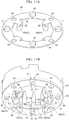
Fig. 11A is an upper perspective view of a rotation-stopping member illustrated inFig. 10 ; and -
Fig. 11B is a lower perspective view of a yoke and the rotation-stopping member joined through welding to the yoke illustrated inFig. 10 . - An embodiment of the present disclosure will be described below with reference to the drawings.
- It should be noted that some of the gaps formed between the members, clearances between the members, and the like illustrated in the drawings may be exaggerated for easier understanding of the disclosure and for convenience in the preparation of the drawings. Further, descriptions indicating positions and directions such as up, down, left, and right in the present specification are based on the drawings, and do not indicate the positions and directions in the actual use.
-
Fig. 1 is a plan view of an embodiment of a stator unit according to the present disclosure,Fig. 2 andFig. 3 are cross-sectional views ofFig. 1 taken along arrow A-A and arrow B-B, respectively,Fig. 4 is an upper perspective view of a rotation-stopping member for use in the stator unit illustrated inFig. 1 to Fig. 3 ,Fig. 5 is a lower perspective view of a yoke and the rotation-stopping member joined through welding to the yoke illustrated inFig. 2 andFig. 3 , andFig. 6 to Fig. 8 are respectively an underside view, a right-side view (a reversed view ofFig. 6 taken along arrow C), and a cross-sectional view taken along arrow D1-D1 (a reversed cross-sectional view ofFig. 6 taken along arrow D2-D2) ofFig. 5 . - It should be noted that portions illustrated in
Fig. 1 to Fig. 8 are denoted by the same reference numerals as those denoting the respective portions of theconventional stator units Fig. 9 to Figs. 11A and11B, and the overlapping descriptions are omitted. The following description is provided emphasizing the differences. - Similarly to the
stator units stator unit 10 of the present embodiment is externally and securely fitted to thecan 120 that is securely attached to thevalve body 110 of the motor-drivenvalve 100 as illustrated inFig. 9 , and constitutes a stepping motor, together with a rotor (not shown) disposed inside thecan 120. - Similarly to the
stator unit 90 illustrated inFig. 10 , thestator unit 10 of the present embodiment includes themold resin 19 made of a thermosetting resin having low hardness, such as a urethane resin, and a portion sealed with themold resin 19 is formed as the stator body 20 (seeFig. 2 andFig. 3 ). The outer periphery surface of thestator body 20, except for its underside, is covered with thecover 57 made of a thermoplastic resin, such as an ABS. - A lower portion of the
mold resin 19 of thestator body 20 is provided with the rotation-stoppingmember 30 made of a conductive metal plate so as to be embedded in themold resin 19 such that theengagement pieces 37 facing downward of theengagement plate portions 35 provided on the inner periphery side each project partially or entirely from themold resin 19. This rotation-stoppingmember 30 has substantially the same basic configuration as that of the rotation-stoppingmember 30 illustrated inFig. 9 to Figs. 11A and11B . - That is, the rotation-stopping
member 30, which is produced through die-cutting and press working of a conductive metal plate, such as SUS, includes the annular flat plate portion (the annular base plate portion) 31 with theopening 32 through which thecan 120 can be inserted, the annularflat plate portion 31 having eightround holes 33 in total formed at an interval of 45°. - On the side of the opening 32 (the inner periphery side) of the annular
flat plate portion 31 of the rotation-stoppingmember 30, fourengagement plate portions 35, each having an inverted L shape, are cut and raised (formed by bending) at an interval of 90°, and theengagement pieces 37 facing downward (in a direction opposite to the side of the adjacent yoke 51) of theengagement plate portions 35 each have formed therein a round or elongated hole-shapedengagement hole 38. - Further, of the eight
round holes 33 in total formed at an interval of 45°, between the adjacent round holes (33-33) of each of four sets of those, four rectangular projectingpieces 39 are each substantially perpendicularly cut and raised from the annularflat plate portion 31 facing upward (toward the side of the adjacent yoke 51). That is, herein, each projectingpiece 39 is formed so as to be cut and raised upward from a portion between the inner periphery and the outer periphery (more specifically, a substantially center portion in the radial direction) of the annularflat plate portion 31. - In the rotation-stopping
member 30 of the present embodiment, for example, the aforementioned eightround holes 33 and fourengagement plate portions 35 are formed through die-cutting and press working, and the four projectingpieces 39 are formed through separate die-cutting and press working. - The upper end faces (the tip end portions) of the four projecting
pieces 39, which have an identical shape and are bent and raised upward from the annularflat plate portion 31, abut and are joined, through resistance welding, to an underside (an annular flat surface portion) 51d of theyoke 51 positioned at the lowest (a welded portion K3), prior to the assembling of the stator coils 50A and 50B. This joining through welding is performed such that the positioning of the rotation-stoppingmember 30 relative to the underside (the annular flat surface portion) 51d of theyoke 51 in the vertical and circumferential directions is performed using jigs or the like, so as to properly set the relative positional relation between theyoke 51 and the rotation-stoppingmember 30. - In this manner, after the four projecting
pieces 39 provided in the rotation-stoppingmember 30 are joined through welding to theunderside 51d of theyoke 51, the stator coils 50A and 50B are assembled, the assembledstator coils cover 57 is placed in advance, and a thermosetting resin having low hardness, such as a urethane resin, as the mold resin, is injected into the mold through vacuum casting and then hardened in a drying furnace. Then, the stator coils 50A and 50B are demolded, and thestator unit 10 is obtained, in which portions including the surroundings of the projectingpieces 39 of the rotation-stoppingmember 30 are covered and filled with themold resin 19 of a thermosetting resin having low hardness, such as a urethane resin, and sealed. - The
stator unit 10 obtained as such is externally fitted to thecan 120, and fourprojections 122 formed in thecan 120 are fitted into their respective engagement holes 38 formed in theengagement pieces 37 facing downward of the fourengagement plate portions 35, so that theengagement pieces 37 are outwardly distorted to allow, with their spring force, theprojections 122 to firmly fit into the engagement holes 38. Thus, thestator unit 10 is externally and securely fitted to thecan 120, so that their relative rotation and relative movement are prevented. - In the
stator unit 10 of the present embodiment configured as such, the four projectingpieces 39 that are bent and raised toward the side of theyoke 51 are provided in the rotation-stoppingmember 30 and are joined through welding to theyoke 51, and thus, the rotation-stoppingmember 30 can be firmly fixed to thestator body 20, and also, the positioning of the stator coils 50A and 50B can be relatively properly performed. - Further, the rotation-stopping
member 30 with the projectingpieces 39 can be formed as a single component through, for example, die-cutting and press working, and thus can significantly reduce the number of components and also the number of welded portions (the number of times of welding) by half, so that parts cost and production cost can be reduced, as compared to the stator units as in the aforementioned conventional examples that use the rotation-stoppingmember 30 with theseparate seatings 41. In addition, since the contact area between the projectingpieces 39 and theyoke 51 at the time of welding is reduced, resistance welding is facilitated, so that sufficient strength of the welded portions can be secured. Furthermore, advantageous effects can be obtained that variations in the clearance between theyoke 51 and the rotation-stoppingmember 30, that is, those in the positional relations among the stator coils 50A and 50B, thecan 120, the rotor, and the like can be reduced. - In addition to the foregoing, the rotation-stopping
member 30 including the four projectingpieces 39 is made of conductive metal, such as SUS, and thus, similarly to thestator units Fig. 9 to Figs. 11A and11B , theyokes can 120, and thevalve body 110 are electrically connected via the rotation-stoppingmember 30 including the four projectingpieces 39. Thus, even when high-voltage noise is applied to the stator coils 50A and 50B, theyokes can 120 are at the same potential, which can prevent undesirable discharge that may be generated between theyokes can 120, thereby enabling to reduce adverse effects on the peripheral circuits. - It should be noted that it is needless to mention that the configuration of the stator coil, the types of the mold resin, and the like are not limited to those in the aforementioned embodiment. For example, although a urethane resin is used as the mold resin in the aforementioned embodiment, a thermosetting resin, such as a silicone resin and an epoxy resin, may also be adopted. Further, it is obvious that the number, the shape, the aspect of the arrangement, etc. of the projecting
pieces 39,engagement pieces 37, etc. that are formed in the annular flat plate portion (the annular base plate portion) 31 of the rotation-stoppingmember 30 may also be changed, as appropriate. - Moreover, the present disclosure may be applied not only to the ring-like rotation-stopping member such as the aforementioned rotation-stopping
member 30 that is externally fitted to thecan 120, but also to a bifurcated one, etc. as shown in Patent Literature 2, for example, which has a base plate portion and engagement pieces for stopping rotation (a pair of circular sandwiching portions) provided downward (facing in the direction opposite to the side of the yoke) from the base plate portion. In this case, the base plate portion disposed on the lower side of the yoke may be provided with projecting pieces that are bent and raised toward the side of the yoke from the base plate portion, and the tip end portions of the projecting pieces may be joined through welding to the underside of the yoke. -
- 10
- Stator unit
- 19
- Mold resin
- 20
- Stator body
- 30
- Rotation-stopping member
- 31
- Annular flat plate portion (annular base plate portion)
- 32
- Opening
- 33
- Round hole
- 35
- Engagement plate portion
- 37
- Engagement piece
- 38
- Engagement hole
- 39
- Projecting piece
- 50A, 50B
- Stator coil
- 51, 52
- Yoke
- 51d
- Annular flat surface portion
- 55
- Bobbin
- 56
- Coil
- 57
- Cover
- 58
- Magnetic-pole teeth
- 60
- Stator body
- 61
- Fit-insertion hole
- 100
- Motor-driven valve
- 110
- Valve body
- 120
- Can
- 122
- Projection
- K1 to K3
- Welded portion
Claims (9)
- A stator unit, comprising:a stator body including a stator coil having a yoke, a bobbin attached to the yoke, and a coil wound around the bobbin, an outer side of the stator coil being sealed with a mold resin; anda rotation-stopping member disposed adjacent to the yoke of the stator body,wherein the rotation-stopping member has a base plate portion, an engagement piece for stopping rotation that is provided facing in a direction opposite to a side of the yoke from the base plate portion, and a projecting piece that is bent and raised toward the side of the yoke from the base plate portion, a tip end portion of the projecting piece being joined through welding to the yoke.
- A stator unit comprising:a stator body including a stator coil having a yoke, a bobbin attached to the yoke, and a coil wound around the bobbin, an outer side of the stator coil being sealed with a mold resin; anda rotation-stopping member disposed adjacent to the yoke of the stator body,wherein the rotation-stopping member has an annular base plate portion, an engagement piece for stopping rotation that is provided facing in a direction opposite to a side of the yoke from the base plate portion, and a projecting piece that is bent and raised toward the side of the yoke from the base plate portion, a tip end portion of the projecting piece being joined through welding to the yoke.
- The stator unit according to claim 2, wherein the rotation-stopping member is embedded in the mold resin such that the engagement piece partially or entirely projects from the mold resin.
- The stator unit according to claim 2 or 3, wherein the engagement piece is provided in an engagement plate portion that is bent from an inner periphery side of the base plate portion in the direction opposite to the side of the yoke.
- The stator unit according to any one of claims 2 to 4, wherein the projecting piece is cut and raised from a portion between an inner periphery and an outer periphery of the base plate portion toward the side of the yoke.
- The stator unit according to any one of claims 2 to 5, wherein the engagement piece includes three or more engagement pieces provided at an equiangular interval in a circumferential direction and the projecting piece includes three or more projecting pieces provided likewise.
- The stator unit according to any one of claims 1 to 6, wherein a urethane resin, a silicone resin, or an epoxy resin is used as the mold resin.
- The stator unit according to any one of claims 1 to 7, wherein the rotation-stopping member is made of a conductive metal plate.
- A motor-driven valve comprising the stator unit according to any one of claims 1 to 8, wherein the stator unit is externally and securely fitted to a can that is securely attached to a valve body.
Applications Claiming Priority (2)
| Application Number | Priority Date | Filing Date | Title |
|---|---|---|---|
| JP2018026029A JP6895684B2 (en) | 2018-02-16 | 2018-02-16 | Stator unit and electric valve equipped with it |
| PCT/JP2019/000588 WO2019159573A1 (en) | 2018-02-16 | 2019-01-10 | Stator unit and electric valve provided with same |
Publications (3)
| Publication Number | Publication Date |
|---|---|
| EP3754815A1 true EP3754815A1 (en) | 2020-12-23 |
| EP3754815A4 EP3754815A4 (en) | 2021-11-10 |
| EP3754815B1 EP3754815B1 (en) | 2024-06-05 |
Family
ID=67618616
Family Applications (1)
| Application Number | Title | Priority Date | Filing Date |
|---|---|---|---|
| EP19754940.5A Active EP3754815B1 (en) | 2018-02-16 | 2019-01-10 | Electric valve provided with a stator unit |
Country Status (4)
| Country | Link |
|---|---|
| EP (1) | EP3754815B1 (en) |
| JP (2) | JP6895684B2 (en) |
| CN (1) | CN111742468B (en) |
| WO (1) | WO2019159573A1 (en) |
Cited By (2)
| Publication number | Priority date | Publication date | Assignee | Title |
|---|---|---|---|---|
| JP2023076922A (en) * | 2021-11-24 | 2023-06-05 | 株式会社鷺宮製作所 | Motor-operated valve stators, motor-operated valves and refrigeration cycle systems |
| EP4299957A4 (en) * | 2021-06-24 | 2024-08-07 | BYD Company Limited | ELECTRIC VALVE |
Families Citing this family (6)
| Publication number | Priority date | Publication date | Assignee | Title |
|---|---|---|---|---|
| JP7349307B2 (en) * | 2019-09-27 | 2023-09-22 | 株式会社鷺宮製作所 | Stator and motorized valve for motorized valves |
| JP7280622B2 (en) * | 2020-08-28 | 2023-05-24 | 株式会社不二工機 | Stator unit, motor-operated valve, and stator unit manufacturing method |
| JP7153944B2 (en) * | 2020-09-24 | 2022-10-17 | 株式会社不二工機 | Stator unit manufacturing method and stator unit |
| JP7384411B2 (en) * | 2020-09-24 | 2023-11-21 | 株式会社不二工機 | electric valve |
| JP7646198B2 (en) | 2021-06-14 | 2025-03-17 | 株式会社不二工機 | Stator unit, motor-operated valve, and method for manufacturing the stator unit |
| WO2023207935A1 (en) * | 2022-04-25 | 2023-11-02 | 浙江三花汽车零部件有限公司 | Fluid control assembly |
Family Cites Families (10)
| Publication number | Priority date | Publication date | Assignee | Title |
|---|---|---|---|---|
| JP3780348B2 (en) * | 1996-02-27 | 2006-05-31 | 株式会社鷺宮製作所 | Electromagnetic coil in motorized valve |
| CN1248390C (en) * | 1999-04-20 | 2006-03-29 | 三菱电机株式会社 | Motor shaft for rotary/direct motion conversion motor and manufacturing method thereof |
| JP4084939B2 (en) | 2001-12-14 | 2008-04-30 | 株式会社鷺宮製作所 | Stator coil of stepping motor for electric valve |
| JP4200281B2 (en) | 2003-02-19 | 2008-12-24 | パナソニック株式会社 | Molded motor |
| JP4515045B2 (en) | 2003-04-02 | 2010-07-28 | 株式会社不二工機 | Motorized valve |
| JP4246541B2 (en) | 2003-05-07 | 2009-04-02 | 株式会社鷺宮製作所 | Motorized valve |
| JP5707114B2 (en) * | 2010-12-06 | 2015-04-22 | 株式会社不二工機 | Electric valve stator and electric valve using the same |
| JP6023569B2 (en) * | 2012-12-05 | 2016-11-09 | 小倉クラッチ株式会社 | Electromagnetic drive device and method of manufacturing electromagnetic drive device |
| JP6053601B2 (en) * | 2013-04-25 | 2016-12-27 | 株式会社不二工機 | Stator unit |
| JP6434236B2 (en) | 2014-07-03 | 2018-12-05 | 株式会社不二工機 | Motorized valve |
-
2018
- 2018-02-16 JP JP2018026029A patent/JP6895684B2/en active Active
-
2019
- 2019-01-10 CN CN201980013547.6A patent/CN111742468B/en active Active
- 2019-01-10 EP EP19754940.5A patent/EP3754815B1/en active Active
- 2019-01-10 WO PCT/JP2019/000588 patent/WO2019159573A1/en not_active Ceased
-
2021
- 2021-06-01 JP JP2021092310A patent/JP7286186B2/en active Active
Cited By (4)
| Publication number | Priority date | Publication date | Assignee | Title |
|---|---|---|---|---|
| EP4299957A4 (en) * | 2021-06-24 | 2024-08-07 | BYD Company Limited | ELECTRIC VALVE |
| US12379043B2 (en) | 2021-06-24 | 2025-08-05 | Byd Company Limited | Electric valve |
| AU2022299892B2 (en) * | 2021-06-24 | 2025-09-11 | Byd Company Limited | Electric valve |
| JP2023076922A (en) * | 2021-11-24 | 2023-06-05 | 株式会社鷺宮製作所 | Motor-operated valve stators, motor-operated valves and refrigeration cycle systems |
Also Published As
| Publication number | Publication date |
|---|---|
| JP2019146299A (en) | 2019-08-29 |
| CN111742468B (en) | 2022-09-30 |
| CN111742468A (en) | 2020-10-02 |
| JP2021132527A (en) | 2021-09-09 |
| JP7286186B2 (en) | 2023-06-05 |
| JP6895684B2 (en) | 2021-06-30 |
| WO2019159573A1 (en) | 2019-08-22 |
| EP3754815A4 (en) | 2021-11-10 |
| EP3754815B1 (en) | 2024-06-05 |
Similar Documents
| Publication | Publication Date | Title |
|---|---|---|
| EP3754815B1 (en) | Electric valve provided with a stator unit | |
| US9385571B2 (en) | Stator member | |
| US9318933B2 (en) | Stepping motor with snapping front boss and securing pins | |
| EP3358715B1 (en) | Stator, motor, and pump device | |
| EP3200320A1 (en) | Stator and manufacturing method therefor | |
| CN108512324B (en) | Motor and method for manufacturing motor | |
| KR20170122486A (en) | Terminal and Motor having the same | |
| JP2021058000A (en) | Motor and transmission device | |
| CN107852044B (en) | Stator, motor and air conditioner | |
| CN111130246A (en) | Rotors, Stators and Motors | |
| JP7651878B2 (en) | Method for manufacturing busbar unit, busbar unit, and motor | |
| JP2019180134A (en) | motor | |
| JP2019054622A (en) | Stator, motor, and stator manufacturing method | |
| CN110323878B (en) | Electric motor | |
| JP2019126123A (en) | motor | |
| CN111384811A (en) | Motor with a stator having a stator core | |
| JP2020167826A (en) | Motor and valve body drive | |
| US12407212B2 (en) | Motor with a motor terminal | |
| CN108123580A (en) | Manufacturing method, stator and the motor of stator | |
| CN210780273U (en) | Rotor and motor | |
| CN216564729U (en) | Motor, air supply device and smoke exhaust ventilator | |
| JP7219424B2 (en) | Rotating electric machine | |
| CN110323887B (en) | Electric motor | |
| JP2010279174A (en) | Vibrating motor | |
| JP2006187156A (en) | Commutator manufacturing method and commutator using the same |
Legal Events
| Date | Code | Title | Description |
|---|---|---|---|
| STAA | Information on the status of an ep patent application or granted ep patent |
Free format text: STATUS: THE INTERNATIONAL PUBLICATION HAS BEEN MADE |
|
| PUAI | Public reference made under article 153(3) epc to a published international application that has entered the european phase |
Free format text: ORIGINAL CODE: 0009012 |
|
| STAA | Information on the status of an ep patent application or granted ep patent |
Free format text: STATUS: REQUEST FOR EXAMINATION WAS MADE |
|
| 17P | Request for examination filed |
Effective date: 20200908 |
|
| AK | Designated contracting states |
Kind code of ref document: A1 Designated state(s): AL AT BE BG CH CY CZ DE DK EE ES FI FR GB GR HR HU IE IS IT LI LT LU LV MC MK MT NL NO PL PT RO RS SE SI SK SM TR |
|
| AX | Request for extension of the european patent |
Extension state: BA ME |
|
| DAV | Request for validation of the european patent (deleted) | ||
| DAX | Request for extension of the european patent (deleted) | ||
| REG | Reference to a national code |
Ref country code: DE Free format text: PREVIOUS MAIN CLASS: H02K0005000000 Ref country code: DE Ref legal event code: R079 Ref document number: 602019053259 Country of ref document: DE Free format text: PREVIOUS MAIN CLASS: H02K0005000000 Ipc: F16K0027000000 |
|
| A4 | Supplementary search report drawn up and despatched |
Effective date: 20211008 |
|
| RIC1 | Information provided on ipc code assigned before grant |
Ipc: H02K 21/14 20060101ALI20211004BHEP Ipc: H02K 5/128 20060101ALI20211004BHEP Ipc: F16K 31/04 20060101ALI20211004BHEP Ipc: F16K 27/00 20060101AFI20211004BHEP |
|
| GRAP | Despatch of communication of intention to grant a patent |
Free format text: ORIGINAL CODE: EPIDOSNIGR1 |
|
| STAA | Information on the status of an ep patent application or granted ep patent |
Free format text: STATUS: GRANT OF PATENT IS INTENDED |
|
| INTG | Intention to grant announced |
Effective date: 20240125 |
|
| GRAS | Grant fee paid |
Free format text: ORIGINAL CODE: EPIDOSNIGR3 |
|
| GRAA | (expected) grant |
Free format text: ORIGINAL CODE: 0009210 |
|
| STAA | Information on the status of an ep patent application or granted ep patent |
Free format text: STATUS: THE PATENT HAS BEEN GRANTED |
|
| AK | Designated contracting states |
Kind code of ref document: B1 Designated state(s): AL AT BE BG CH CY CZ DE DK EE ES FI FR GB GR HR HU IE IS IT LI LT LU LV MC MK MT NL NO PL PT RO RS SE SI SK SM TR |
|
| REG | Reference to a national code |
Ref country code: CH Ref legal event code: EP |
|
| REG | Reference to a national code |
Ref country code: DE Ref legal event code: R096 Ref document number: 602019053259 Country of ref document: DE |
|
| REG | Reference to a national code |
Ref country code: IE Ref legal event code: FG4D |
|
| REG | Reference to a national code |
Ref country code: LT Ref legal event code: MG9D |
|
| PG25 | Lapsed in a contracting state [announced via postgrant information from national office to epo] |
Ref country code: BG Free format text: LAPSE BECAUSE OF FAILURE TO SUBMIT A TRANSLATION OF THE DESCRIPTION OR TO PAY THE FEE WITHIN THE PRESCRIBED TIME-LIMIT Effective date: 20240605 |
|
| REG | Reference to a national code |
Ref country code: NL Ref legal event code: MP Effective date: 20240605 |
|
| PG25 | Lapsed in a contracting state [announced via postgrant information from national office to epo] |
Ref country code: FI Free format text: LAPSE BECAUSE OF FAILURE TO SUBMIT A TRANSLATION OF THE DESCRIPTION OR TO PAY THE FEE WITHIN THE PRESCRIBED TIME-LIMIT Effective date: 20240605 Ref country code: HR Free format text: LAPSE BECAUSE OF FAILURE TO SUBMIT A TRANSLATION OF THE DESCRIPTION OR TO PAY THE FEE WITHIN THE PRESCRIBED TIME-LIMIT Effective date: 20240605 |
|
| PG25 | Lapsed in a contracting state [announced via postgrant information from national office to epo] |
Ref country code: GR Free format text: LAPSE BECAUSE OF FAILURE TO SUBMIT A TRANSLATION OF THE DESCRIPTION OR TO PAY THE FEE WITHIN THE PRESCRIBED TIME-LIMIT Effective date: 20240906 |
|
| PG25 | Lapsed in a contracting state [announced via postgrant information from national office to epo] |
Ref country code: ES Free format text: LAPSE BECAUSE OF FAILURE TO SUBMIT A TRANSLATION OF THE DESCRIPTION OR TO PAY THE FEE WITHIN THE PRESCRIBED TIME-LIMIT Effective date: 20240605 |
|
| PG25 | Lapsed in a contracting state [announced via postgrant information from national office to epo] |
Ref country code: LV Free format text: LAPSE BECAUSE OF FAILURE TO SUBMIT A TRANSLATION OF THE DESCRIPTION OR TO PAY THE FEE WITHIN THE PRESCRIBED TIME-LIMIT Effective date: 20240605 |
|
| PG25 | Lapsed in a contracting state [announced via postgrant information from national office to epo] |
Ref country code: NO Free format text: LAPSE BECAUSE OF FAILURE TO SUBMIT A TRANSLATION OF THE DESCRIPTION OR TO PAY THE FEE WITHIN THE PRESCRIBED TIME-LIMIT Effective date: 20240905 Ref country code: LV Free format text: LAPSE BECAUSE OF FAILURE TO SUBMIT A TRANSLATION OF THE DESCRIPTION OR TO PAY THE FEE WITHIN THE PRESCRIBED TIME-LIMIT Effective date: 20240605 Ref country code: HR Free format text: LAPSE BECAUSE OF FAILURE TO SUBMIT A TRANSLATION OF THE DESCRIPTION OR TO PAY THE FEE WITHIN THE PRESCRIBED TIME-LIMIT Effective date: 20240605 Ref country code: GR Free format text: LAPSE BECAUSE OF FAILURE TO SUBMIT A TRANSLATION OF THE DESCRIPTION OR TO PAY THE FEE WITHIN THE PRESCRIBED TIME-LIMIT Effective date: 20240906 Ref country code: FI Free format text: LAPSE BECAUSE OF FAILURE TO SUBMIT A TRANSLATION OF THE DESCRIPTION OR TO PAY THE FEE WITHIN THE PRESCRIBED TIME-LIMIT Effective date: 20240605 Ref country code: ES Free format text: LAPSE BECAUSE OF FAILURE TO SUBMIT A TRANSLATION OF THE DESCRIPTION OR TO PAY THE FEE WITHIN THE PRESCRIBED TIME-LIMIT Effective date: 20240605 Ref country code: BG Free format text: LAPSE BECAUSE OF FAILURE TO SUBMIT A TRANSLATION OF THE DESCRIPTION OR TO PAY THE FEE WITHIN THE PRESCRIBED TIME-LIMIT Effective date: 20240605 Ref country code: RS Free format text: LAPSE BECAUSE OF FAILURE TO SUBMIT A TRANSLATION OF THE DESCRIPTION OR TO PAY THE FEE WITHIN THE PRESCRIBED TIME-LIMIT Effective date: 20240905 |
|
| PG25 | Lapsed in a contracting state [announced via postgrant information from national office to epo] |
Ref country code: NL Free format text: LAPSE BECAUSE OF FAILURE TO SUBMIT A TRANSLATION OF THE DESCRIPTION OR TO PAY THE FEE WITHIN THE PRESCRIBED TIME-LIMIT Effective date: 20240605 |
|
| REG | Reference to a national code |
Ref country code: AT Ref legal event code: MK05 Ref document number: 1692677 Country of ref document: AT Kind code of ref document: T Effective date: 20240605 |
|
| PG25 | Lapsed in a contracting state [announced via postgrant information from national office to epo] |
Ref country code: NL Free format text: LAPSE BECAUSE OF FAILURE TO SUBMIT A TRANSLATION OF THE DESCRIPTION OR TO PAY THE FEE WITHIN THE PRESCRIBED TIME-LIMIT Effective date: 20240605 |
|
| PG25 | Lapsed in a contracting state [announced via postgrant information from national office to epo] |
Ref country code: PT Free format text: LAPSE BECAUSE OF FAILURE TO SUBMIT A TRANSLATION OF THE DESCRIPTION OR TO PAY THE FEE WITHIN THE PRESCRIBED TIME-LIMIT Effective date: 20241007 |
|
| PG25 | Lapsed in a contracting state [announced via postgrant information from national office to epo] |
Ref country code: PT Free format text: LAPSE BECAUSE OF FAILURE TO SUBMIT A TRANSLATION OF THE DESCRIPTION OR TO PAY THE FEE WITHIN THE PRESCRIBED TIME-LIMIT Effective date: 20241007 |
|
| PG25 | Lapsed in a contracting state [announced via postgrant information from national office to epo] |
Ref country code: PL Free format text: LAPSE BECAUSE OF FAILURE TO SUBMIT A TRANSLATION OF THE DESCRIPTION OR TO PAY THE FEE WITHIN THE PRESCRIBED TIME-LIMIT Effective date: 20240605 |
|
| PG25 | Lapsed in a contracting state [announced via postgrant information from national office to epo] |
Ref country code: EE Free format text: LAPSE BECAUSE OF FAILURE TO SUBMIT A TRANSLATION OF THE DESCRIPTION OR TO PAY THE FEE WITHIN THE PRESCRIBED TIME-LIMIT Effective date: 20240605 |
|
| PG25 | Lapsed in a contracting state [announced via postgrant information from national office to epo] |
Ref country code: AT Free format text: LAPSE BECAUSE OF FAILURE TO SUBMIT A TRANSLATION OF THE DESCRIPTION OR TO PAY THE FEE WITHIN THE PRESCRIBED TIME-LIMIT Effective date: 20240605 Ref country code: IS Free format text: LAPSE BECAUSE OF FAILURE TO SUBMIT A TRANSLATION OF THE DESCRIPTION OR TO PAY THE FEE WITHIN THE PRESCRIBED TIME-LIMIT Effective date: 20241005 |
|
| PG25 | Lapsed in a contracting state [announced via postgrant information from national office to epo] |
Ref country code: CZ Free format text: LAPSE BECAUSE OF FAILURE TO SUBMIT A TRANSLATION OF THE DESCRIPTION OR TO PAY THE FEE WITHIN THE PRESCRIBED TIME-LIMIT Effective date: 20240605 |
|
| PG25 | Lapsed in a contracting state [announced via postgrant information from national office to epo] |
Ref country code: RO Free format text: LAPSE BECAUSE OF FAILURE TO SUBMIT A TRANSLATION OF THE DESCRIPTION OR TO PAY THE FEE WITHIN THE PRESCRIBED TIME-LIMIT Effective date: 20240605 Ref country code: SK Free format text: LAPSE BECAUSE OF FAILURE TO SUBMIT A TRANSLATION OF THE DESCRIPTION OR TO PAY THE FEE WITHIN THE PRESCRIBED TIME-LIMIT Effective date: 20240605 |
|
| PG25 | Lapsed in a contracting state [announced via postgrant information from national office to epo] |
Ref country code: SM Free format text: LAPSE BECAUSE OF FAILURE TO SUBMIT A TRANSLATION OF THE DESCRIPTION OR TO PAY THE FEE WITHIN THE PRESCRIBED TIME-LIMIT Effective date: 20240605 |
|
| PG25 | Lapsed in a contracting state [announced via postgrant information from national office to epo] |
Ref country code: SM Free format text: LAPSE BECAUSE OF FAILURE TO SUBMIT A TRANSLATION OF THE DESCRIPTION OR TO PAY THE FEE WITHIN THE PRESCRIBED TIME-LIMIT Effective date: 20240605 Ref country code: SK Free format text: LAPSE BECAUSE OF FAILURE TO SUBMIT A TRANSLATION OF THE DESCRIPTION OR TO PAY THE FEE WITHIN THE PRESCRIBED TIME-LIMIT Effective date: 20240605 Ref country code: RO Free format text: LAPSE BECAUSE OF FAILURE TO SUBMIT A TRANSLATION OF THE DESCRIPTION OR TO PAY THE FEE WITHIN THE PRESCRIBED TIME-LIMIT Effective date: 20240605 Ref country code: PL Free format text: LAPSE BECAUSE OF FAILURE TO SUBMIT A TRANSLATION OF THE DESCRIPTION OR TO PAY THE FEE WITHIN THE PRESCRIBED TIME-LIMIT Effective date: 20240605 Ref country code: IS Free format text: LAPSE BECAUSE OF FAILURE TO SUBMIT A TRANSLATION OF THE DESCRIPTION OR TO PAY THE FEE WITHIN THE PRESCRIBED TIME-LIMIT Effective date: 20241005 Ref country code: EE Free format text: LAPSE BECAUSE OF FAILURE TO SUBMIT A TRANSLATION OF THE DESCRIPTION OR TO PAY THE FEE WITHIN THE PRESCRIBED TIME-LIMIT Effective date: 20240605 Ref country code: CZ Free format text: LAPSE BECAUSE OF FAILURE TO SUBMIT A TRANSLATION OF THE DESCRIPTION OR TO PAY THE FEE WITHIN THE PRESCRIBED TIME-LIMIT Effective date: 20240605 Ref country code: AT Free format text: LAPSE BECAUSE OF FAILURE TO SUBMIT A TRANSLATION OF THE DESCRIPTION OR TO PAY THE FEE WITHIN THE PRESCRIBED TIME-LIMIT Effective date: 20240605 |
|
| PG25 | Lapsed in a contracting state [announced via postgrant information from national office to epo] |
Ref country code: IT Free format text: LAPSE BECAUSE OF FAILURE TO SUBMIT A TRANSLATION OF THE DESCRIPTION OR TO PAY THE FEE WITHIN THE PRESCRIBED TIME-LIMIT Effective date: 20240605 |
|
| REG | Reference to a national code |
Ref country code: DE Ref legal event code: R097 Ref document number: 602019053259 Country of ref document: DE |
|
| PGFP | Annual fee paid to national office [announced via postgrant information from national office to epo] |
Ref country code: DE Payment date: 20250128 Year of fee payment: 7 |
|
| PLBE | No opposition filed within time limit |
Free format text: ORIGINAL CODE: 0009261 |
|
| STAA | Information on the status of an ep patent application or granted ep patent |
Free format text: STATUS: NO OPPOSITION FILED WITHIN TIME LIMIT |
|
| PG25 | Lapsed in a contracting state [announced via postgrant information from national office to epo] |
Ref country code: DK Free format text: LAPSE BECAUSE OF FAILURE TO SUBMIT A TRANSLATION OF THE DESCRIPTION OR TO PAY THE FEE WITHIN THE PRESCRIBED TIME-LIMIT Effective date: 20240605 |
|
| PGFP | Annual fee paid to national office [announced via postgrant information from national office to epo] |
Ref country code: FR Payment date: 20250123 Year of fee payment: 7 |
|
| 26N | No opposition filed |
Effective date: 20250306 |
|
| REG | Reference to a national code |
Ref country code: CH Ref legal event code: PL |
|
| PG25 | Lapsed in a contracting state [announced via postgrant information from national office to epo] |
Ref country code: SE Free format text: LAPSE BECAUSE OF FAILURE TO SUBMIT A TRANSLATION OF THE DESCRIPTION OR TO PAY THE FEE WITHIN THE PRESCRIBED TIME-LIMIT Effective date: 20240605 |
|
| PG25 | Lapsed in a contracting state [announced via postgrant information from national office to epo] |
Ref country code: MC Free format text: LAPSE BECAUSE OF FAILURE TO SUBMIT A TRANSLATION OF THE DESCRIPTION OR TO PAY THE FEE WITHIN THE PRESCRIBED TIME-LIMIT Effective date: 20240605 Ref country code: LU Free format text: LAPSE BECAUSE OF NON-PAYMENT OF DUE FEES Effective date: 20250110 |
|
| GBPC | Gb: european patent ceased through non-payment of renewal fee |
Effective date: 20250110 |
|
| PG25 | Lapsed in a contracting state [announced via postgrant information from national office to epo] |
Ref country code: GB Free format text: LAPSE BECAUSE OF NON-PAYMENT OF DUE FEES Effective date: 20250110 Ref country code: BE Free format text: LAPSE BECAUSE OF NON-PAYMENT OF DUE FEES Effective date: 20250131 |
|
| PG25 | Lapsed in a contracting state [announced via postgrant information from national office to epo] |
Ref country code: CH Free format text: LAPSE BECAUSE OF NON-PAYMENT OF DUE FEES Effective date: 20250131 |
|
| REG | Reference to a national code |
Ref country code: BE Ref legal event code: MM Effective date: 20250131 |
|
| PG25 | Lapsed in a contracting state [announced via postgrant information from national office to epo] |
Ref country code: IE Free format text: LAPSE BECAUSE OF NON-PAYMENT OF DUE FEES Effective date: 20250110 |