EP3754579A1 - Barcode generation device and barcode generation method - Google Patents
Barcode generation device and barcode generation method Download PDFInfo
- Publication number
- EP3754579A1 EP3754579A1 EP20153536.6A EP20153536A EP3754579A1 EP 3754579 A1 EP3754579 A1 EP 3754579A1 EP 20153536 A EP20153536 A EP 20153536A EP 3754579 A1 EP3754579 A1 EP 3754579A1
- Authority
- EP
- European Patent Office
- Prior art keywords
- barcode
- display
- processor
- barcodes
- split
- Prior art date
- Legal status (The legal status is an assumption and is not a legal conclusion. Google has not performed a legal analysis and makes no representation as to the accuracy of the status listed.)
- Withdrawn
Links
Images


Classifications
-
- G—PHYSICS
- G06—COMPUTING; CALCULATING OR COUNTING
- G06Q—INFORMATION AND COMMUNICATION TECHNOLOGY [ICT] SPECIALLY ADAPTED FOR ADMINISTRATIVE, COMMERCIAL, FINANCIAL, MANAGERIAL OR SUPERVISORY PURPOSES; SYSTEMS OR METHODS SPECIALLY ADAPTED FOR ADMINISTRATIVE, COMMERCIAL, FINANCIAL, MANAGERIAL OR SUPERVISORY PURPOSES, NOT OTHERWISE PROVIDED FOR
- G06Q20/00—Payment architectures, schemes or protocols
- G06Q20/30—Payment architectures, schemes or protocols characterised by the use of specific devices or networks
- G06Q20/32—Payment architectures, schemes or protocols characterised by the use of specific devices or networks using wireless devices
- G06Q20/327—Short range or proximity payments by means of M-devices
- G06Q20/3274—Short range or proximity payments by means of M-devices using a pictured code, e.g. barcode or QR-code, being displayed on the M-device
-
- G—PHYSICS
- G06—COMPUTING; CALCULATING OR COUNTING
- G06K—GRAPHICAL DATA READING; PRESENTATION OF DATA; RECORD CARRIERS; HANDLING RECORD CARRIERS
- G06K19/00—Record carriers for use with machines and with at least a part designed to carry digital markings
- G06K19/06—Record carriers for use with machines and with at least a part designed to carry digital markings characterised by the kind of the digital marking, e.g. shape, nature, code
- G06K19/06009—Record carriers for use with machines and with at least a part designed to carry digital markings characterised by the kind of the digital marking, e.g. shape, nature, code with optically detectable marking
- G06K19/06046—Constructional details
- G06K19/06112—Constructional details the marking being simulated using a light source, e.g. a barcode shown on a display or a laser beam with time-varying intensity profile
-
- G—PHYSICS
- G06—COMPUTING; CALCULATING OR COUNTING
- G06K—GRAPHICAL DATA READING; PRESENTATION OF DATA; RECORD CARRIERS; HANDLING RECORD CARRIERS
- G06K19/00—Record carriers for use with machines and with at least a part designed to carry digital markings
- G06K19/06—Record carriers for use with machines and with at least a part designed to carry digital markings characterised by the kind of the digital marking, e.g. shape, nature, code
- G06K19/06009—Record carriers for use with machines and with at least a part designed to carry digital markings characterised by the kind of the digital marking, e.g. shape, nature, code with optically detectable marking
- G06K19/06018—Record carriers for use with machines and with at least a part designed to carry digital markings characterised by the kind of the digital marking, e.g. shape, nature, code with optically detectable marking one-dimensional coding
- G06K19/06028—Record carriers for use with machines and with at least a part designed to carry digital markings characterised by the kind of the digital marking, e.g. shape, nature, code with optically detectable marking one-dimensional coding using bar codes
-
- G—PHYSICS
- G06—COMPUTING; CALCULATING OR COUNTING
- G06K—GRAPHICAL DATA READING; PRESENTATION OF DATA; RECORD CARRIERS; HANDLING RECORD CARRIERS
- G06K19/00—Record carriers for use with machines and with at least a part designed to carry digital markings
- G06K19/06—Record carriers for use with machines and with at least a part designed to carry digital markings characterised by the kind of the digital marking, e.g. shape, nature, code
- G06K19/06009—Record carriers for use with machines and with at least a part designed to carry digital markings characterised by the kind of the digital marking, e.g. shape, nature, code with optically detectable marking
- G06K19/06046—Constructional details
- G06K19/06075—Constructional details the marking containing means for error correction
-
- G—PHYSICS
- G06—COMPUTING; CALCULATING OR COUNTING
- G06K—GRAPHICAL DATA READING; PRESENTATION OF DATA; RECORD CARRIERS; HANDLING RECORD CARRIERS
- G06K7/00—Methods or arrangements for sensing record carriers, e.g. for reading patterns
- G06K7/10—Methods or arrangements for sensing record carriers, e.g. for reading patterns by electromagnetic radiation, e.g. optical sensing; by corpuscular radiation
- G06K7/14—Methods or arrangements for sensing record carriers, e.g. for reading patterns by electromagnetic radiation, e.g. optical sensing; by corpuscular radiation using light without selection of wavelength, e.g. sensing reflected white light
- G06K7/1404—Methods for optical code recognition
- G06K7/1408—Methods for optical code recognition the method being specifically adapted for the type of code
- G06K7/1413—1D bar codes
-
- G—PHYSICS
- G06—COMPUTING; CALCULATING OR COUNTING
- G06K—GRAPHICAL DATA READING; PRESENTATION OF DATA; RECORD CARRIERS; HANDLING RECORD CARRIERS
- G06K7/00—Methods or arrangements for sensing record carriers, e.g. for reading patterns
- G06K7/10—Methods or arrangements for sensing record carriers, e.g. for reading patterns by electromagnetic radiation, e.g. optical sensing; by corpuscular radiation
- G06K7/14—Methods or arrangements for sensing record carriers, e.g. for reading patterns by electromagnetic radiation, e.g. optical sensing; by corpuscular radiation using light without selection of wavelength, e.g. sensing reflected white light
- G06K7/1404—Methods for optical code recognition
- G06K7/1439—Methods for optical code recognition including a method step for retrieval of the optical code
-
- G—PHYSICS
- G06—COMPUTING; CALCULATING OR COUNTING
- G06K—GRAPHICAL DATA READING; PRESENTATION OF DATA; RECORD CARRIERS; HANDLING RECORD CARRIERS
- G06K7/00—Methods or arrangements for sensing record carriers, e.g. for reading patterns
- G06K7/10—Methods or arrangements for sensing record carriers, e.g. for reading patterns by electromagnetic radiation, e.g. optical sensing; by corpuscular radiation
- G06K7/14—Methods or arrangements for sensing record carriers, e.g. for reading patterns by electromagnetic radiation, e.g. optical sensing; by corpuscular radiation using light without selection of wavelength, e.g. sensing reflected white light
- G06K7/1404—Methods for optical code recognition
- G06K7/146—Methods for optical code recognition the method including quality enhancement steps
- G06K7/1491—Methods for optical code recognition the method including quality enhancement steps the method including a reconstruction step, e.g. stitching two pieces of bar code together to derive the full bar code
-
- H—ELECTRICITY
- H04—ELECTRIC COMMUNICATION TECHNIQUE
- H04W—WIRELESS COMMUNICATION NETWORKS
- H04W4/00—Services specially adapted for wireless communication networks; Facilities therefor
- H04W4/80—Services using short range communication, e.g. near-field communication [NFC], radio-frequency identification [RFID] or low energy communication
-
- G—PHYSICS
- G06—COMPUTING; CALCULATING OR COUNTING
- G06K—GRAPHICAL DATA READING; PRESENTATION OF DATA; RECORD CARRIERS; HANDLING RECORD CARRIERS
- G06K7/00—Methods or arrangements for sensing record carriers, e.g. for reading patterns
- G06K7/10—Methods or arrangements for sensing record carriers, e.g. for reading patterns by electromagnetic radiation, e.g. optical sensing; by corpuscular radiation
- G06K7/10544—Methods or arrangements for sensing record carriers, e.g. for reading patterns by electromagnetic radiation, e.g. optical sensing; by corpuscular radiation by scanning of the records by radiation in the optical part of the electromagnetic spectrum
- G06K7/10821—Methods or arrangements for sensing record carriers, e.g. for reading patterns by electromagnetic radiation, e.g. optical sensing; by corpuscular radiation by scanning of the records by radiation in the optical part of the electromagnetic spectrum further details of bar or optical code scanning devices
- G06K7/1095—Methods or arrangements for sensing record carriers, e.g. for reading patterns by electromagnetic radiation, e.g. optical sensing; by corpuscular radiation by scanning of the records by radiation in the optical part of the electromagnetic spectrum further details of bar or optical code scanning devices the scanner comprising adaptations for scanning a record carrier that is displayed on a display-screen or the like
Definitions
- Embodiments described herein relate generally to a barcode generation device and a barcode generation method.
- Embodiments provide a barcode generation device and a barcode generation method which are capable of preventing the illegal use of a barcode.
- a barcode generation device includes an interface and a processor.
- the interface receives a barcode display instruction.
- the processor generates a basic barcode in response to the display instruction received by the interface, generates a plurality of barcodes in which noise is superimposed at different positions on the basic barcode, determines whether there is misreading in an image scanned by a barcode reader on a screen on which the plurality of barcodes are sequentially displayed, and sequentially displays the plurality of barcodes on a display device when it is determined that there is no misreading.
- to determine whether there is the misreading comprises to determine whether there is misreading in each of images of a plurality of barcodes in which the noise is superimposed.
- to determine whether there is the misreading comprises to determine whether there is misreading in a combined image which is obtained when the plurality of sequentially displayed barcodes are scanned.
- the basic barcode is generated so as to be decodable by a barcode reader.
- the plurality of barcodes is generated so as to be undecodable by a barcode reader.
- the display device is a smartphone.
- the present invention further relates to a barcode generation device, comprising: an interface configured to receive a barcode display instruction; and a processor configured to generate a basic barcode in response to the barcode display instruction received by the interface, generate a split barcode image group in which the basic barcode is split into a plurality of images that are singly undecodable, and sequentially display the split barcode image group on a display device.
- a barcode generation device comprising: an interface configured to receive a barcode display instruction; and a processor configured to generate a basic barcode in response to the barcode display instruction received by the interface, generate a split barcode image group in which the basic barcode is split into a plurality of images that are singly undecodable, and sequentially display the split barcode image group on a display device.
- the split barcode image group comprises an image group in which the basic barcode is split so that partial regions overlap between adjacent regions.
- the basic barcode is generated so as to be decodable by a barcode reader.
- the split barcode image group is generated so as to be undecodable by a barcode reader.
- the display device is a smartphone.
- the present invention also relates to a barcode generation method, comprising:
- the barcode generation method may further comprise:
- the basic barcode is generated so as to be decodable by a barcode reader.
- the plurality of barcodes is generated so as to be undecodable by a barcode reader.
- the display device is a smartphone.
- the present invention further relates to a barcode generation method, comprising:
- the split barcode image group comprises an image group in which the basic barcode is split so that partial regions overlap between adjacent regions.
- the basic barcode is generated so as to be decodable by a barcode reader.
- the split barcode image group is generated so as to be undecodable by a barcode reader.
- the display device is a smartphone.
- a barcode generation device generates a barcode displayed on a display of a portable terminal such as a smartphone, a mobile phone, or a tablet PC.
- the barcode generation device may be a portable terminal or a computer such as a server capable of communicating with a portable terminal.
- a case of a portable terminal and a case of a server as the barcode generation device will be described.
- FIG. 1 is a block diagram illustrating a configuration example of a portable terminal 10 serving as a barcode generation device according to the first embodiment.
- the portable terminal 10 includes a processor 11, a read-only memory (ROM) 12, a random access memory (RAM) 13, a data memory 14, an interface (panel interface) 15, and a touch panel 16.
- the processor 11 is connected to the ROM 12, the RAM 13, the data memory 14, and the panel interface 15.
- the touch panel 16 includes a display 17 and a touch sensor 18. The touch panel 16 is connected to the processor 11 via the panel interface 15.
- the processor 11 performs various processes by executing programs.
- the processor 11 is, for example, a central processing unit (CPU).
- the processor 11 realizes various processing functions by executing programs stored in the ROM 21 or the data memory 14.
- the processor 11 generates a barcode image to be displayed on the display by executing a barcode generation program.
- the processor 11 displays the generated barcode image on the display 17 by executing a barcode display program.
- the ROM 12 is a non-volatile memory.
- the ROM 12 stores programs and data.
- the ROM 12 stores programs such as an operating system, middleware, and applications.
- the ROM 12 may store data which is referred to when the processor 11 performs various processes.
- the RAM 13 stores working data.
- the RAM 13 is a memory used as a so-called work area.
- the RAM 13 appropriately stores data which is referred to or data which is temporarily used when the processor 11 performs various programs.
- the data memory 14 is a rewritable nonvolatile memory.
- the data memory 14 is configured with, for example, a memory (storage device) such as an electric erasable programmable read-only memory (EEPROM) (registered trademark), a hard disk drive (HDD), a solid-state drive (SSD), and a memory card.
- EEPROM electric erasable programmable read-only memory
- HDD hard disk drive
- SSD solid-state drive
- memory card a memory card
- the panel interface 15 is connected to the touch panel 16.
- the touch panel 16 is an example of a display device connected to an interface in the portable terminal 10.
- the touch panel 16 includes the display 17 as a display unit and the touch sensor 18 as an operation unit.
- the display device connected to the interface in the portable terminal 10 may be a display device capable of displaying a barcode image or may not be a touch panel that includes a touch sensor.
- the touch interface 15 connects the processor 11 to the display 17 and the touch sensor 18 in the touch panel 16.
- the processor 11 controls an image displayed on the display 17 via the panel interface 15.
- the processor 11 acquires an input signal (operation signal) detected by the touch sensor 18 via the panel interface 15.
- the panel interface 15 is an example of an interface that receives a barcode display instruction input on the touch panel 16.
- Programs that are executed by the processor 11 are installed in the ROM 12 or the data memory 14.
- the processor 11 executes a program of an operating system (OS) that manages a basic operation of the portable terminal 10.
- OS operating system
- the processor 11 executes various application programs after the OS is executed.
- FIG. 2 is a schematic diagram illustrating an example of a program group stored in the ROM 12 of the portable terminal 10 according to the first embodiment.
- the ROM 12 stores various programs that are executed by the processor 11.
- the ROM 12 stores an operating system (OS), a barcode display program, and a barcode generation program.
- the OS is a program that manages a basic operation of the portable terminal 10.
- the processor 11 can execute an application program that is based on the OS by executing the OS.
- the barcode display program and the barcode generation program may be generated as application programs operated on the OS.
- the barcode display program and the barcode generation program are an application program for realizing operations described below according to the first embodiment.
- the barcode display program is a program for displaying barcodes on a display device.
- the processor 11 realizes display control of barcode images described below by executing the barcode display program.
- the barcode generation program is a program for generating barcodes.
- the processor 11 generates a basic barcode described below and generates a plurality of barcode images for display by executing the barcode generation program.
- the programs illustrated in FIG. 2 may be stored in a memory so as to be executed by the processor 11 or may be stored in a memory such as the data memory 14 other than the ROM 12.
- the OS may be stored in the ROM 12 and the barcode display program and the barcode generation program may be stored in the data memory 14.
- the portable terminal 10 generates a plurality of barcode images (display images) in which noise is superimposed on the basic barcode and sequentially displays the plurality of barcode images repeatedly.
- a scanner of a barcode reader reads the plurality of sequentially displayed display images as images combined at scan timings.
- the barcode reader can read a barcode in which regions without noise are combined when the scan timings are correct.
- the portable terminal 10 can display the barcode image in which the individual display images are undecodable and cause the barcode reader to read the barcode without noise.
- FIG. 3 is a diagram illustrating examples of a plurality of barcode images (display images) 31A and 31B generated by superimposing noise in a basic barcode 30.
- the barcode image 31A is a first display image generated by superimposing noise on one portion on the left side of the basic barcode 30.
- the barcode image 31B is a second display image generated by superimposing noise on one portion on the right side of the basic barcode 30.
- FIG. 4 is a diagram illustrating a relationship between display control of the plurality of barcode images 31A and 31B in which noise is superimposed and scanned images 32a to 32d which are scan results.
- the portable terminal 10 alternately displays the barcode images 31A and 31B on the display 17.
- a scanner that scans a display screen of the display 17 in a predetermined direction (direction a) reads the barcode images 31A and 31B as a combined image at a scan timing. That is, the images (scanned images) read by the barcode reader can be several patterns in accordance with a relationship between a display timing of each display image on the display 17 and a scan timing.
- FIG. 4 illustrates examples of scanned images 32a to 32d obtained by the barcode reader (the scanner).
- the scanned image 32a is an image in which noise n1 on the left side is superimposed on the basic barcode 30.
- the scanned image 32a is a result obtained when only the barcode image 31A is read.
- the scanned image 32a is undecodable by the barcode reader due to the noise n1.
- the scanned image 32b is an image in which noise n2 on the right side is superimposed on the basic barcode 30.
- the scanned image 32b is a result obtained when only the barcode image 31B is read.
- the scanned image 32b is undecodable by the barcode reader due to the noise n2.
- the scanned image 32c is an image in which the noise n1 on the left side and the noise n2 on the right side are superimposed on the basic barcode 30.
- the scanned image 32c is a result read by combining a region including noise in the barcode image 31A (a region on the left side of the barcode image 31A) and a region including noise in the barcode image 32B (a region on the right side of the barcode image 31B) .
- the scanned image 32c is undecodable by the barcode reader due to the noise n1 and the noise n2.
- the scanned image 32d is an image in which no noise is included in the basic barcode 30.
- the scanned image 32d is a result read by combining a region including no noise in the barcode image 31A (a region on the right side of the barcode image 31A) and a region including no noise in the barcode image 32B (a region on the left side of the barcode image 31B) . Since the scanned image 32d includes no noise and is the read basic barcode, the scanned image 32d is decodable by the barcode reader.
- the barcode reader performs scanning again when the scanned images 32a, 32b, and 32c are undecodable due to noise. That is, within a predetermined time, the barcode reader repeats the scanning until the scanned image 32d (that is, a decodable barcode) is read as a barcode image without noise. As a result, the barcode reader can read a correct barcode (decodable barcode) from the barcode image in which two pieces of noise alternately displayed on the display 17 are superimposed.
- the portable terminal 10 alternately displays the plurality of barcode images (display images) 31A and 31B on the display 17 so that the barcode reader can read the scanned image 32d.
- a decoded result of the scanned image is determined with check digits included in the barcode. Therefore, when noise triggers an incorrect reading even in the scanned image with noise, there is a possibility that check digits are read at a low probability. For example, in WPC, C/D matches and reading is achieved at a probability of 1/10 even in a misreading result in some cases. That is, when random noise is simply added to the basic barcode, there is a possibility of the barcode reader performing misreading in an image with noise.
- the barcode generation device checks whether there is misreading in a plurality of barcode images in which noise is superimposed and an image in which the plurality of barcode images are combined.
- the portable terminal 10 checks whether there is misreading in the barcode image 31A, the barcode image 31B, and a combined image in which the barcode images 31A and 31B are combined.
- FIG. 5 is a flowchart illustrating an operation example of the barcode display process in the portable terminal 10.
- the processor 11 of the portable terminal 10 generates a basic barcode which is read by the barcode reader when a barcode is displayed on the display 17 (ACT11).
- the processor 11 acquires information (barcode information) which is read by the barcode reader.
- the barcode information may be information stored in the data memory 14 or the like, may be information acquired from an external device or the like, or may be information generated through arithmetic processing by the processor 11.
- the processor 11 When the basic barcode is generated, the processor 11 generates a plurality of barcode images (display images) by superimposing noise on the basic barcode (ACT12). The processor 11 generates the plurality of barcode images in which noise is superimposed at different positions on the basic barcode in a scanning direction of the barcode reader. For example, in the example illustrated in FIG. 3 , the processor 11 generates the barcode image 31A in which noise is superimposed in a region on the left side and the barcode image 31B in which noise is superimposed in a region on the right side on the basic barcode 30.
- the processor 11 After the plurality of images in which the noise is superimposed are generated, the processor 11 checks whether there is a possibility of misreading in the generated individual barcode images (ACT13) . When it is determined that there is a possibility of the misreading in any barcode image (YES in ACT13), the process returns to ACT12 and the processor 11 generates a plurality of barcode images in which noise is superimposed at different positions.
- the processor 11 determines whether there is a possibility of misreading in an image (scanned image) when the plurality of barcode images are combined and read (ACT14). When it is determined that there is a possibility of misreading in any scanned image (YES in ACT14), the process returns to ACT12 and the processor 11 generates a plurality of barcode images in which noise is superimposed at different positions.
- the processor 11 When it is determined that there is no misreading in the scanned image in which the plurality of barcode images are combined (NO in ACT14), the processor 11 performs display control such that the plurality of barcode images are sequentially displayed on the display 17 (ACT15) .
- the barcode image 31A as a first display image and the barcode image 31B as a second display image are alternately displayed on the display 17.
- the processor 11 sequentially switches and displays the barcode images 31A and 31B at timings at which the barcode reader can continuously scan the region on the right side of the barcode image 31A and the region on the left side of the barcode image 31B.
- the processor 11 receives an instruction to end the display of the barcode (ACT16) . Until the instruction to end the display of the barcode is received (NO in ACT16), the processor 11 continues the display control of the plurality of barcode images. Conversely, when the instruction to end the display of the barcode is received (YES in ACT16), the processor 11 ends the series of the barcode display process. For example, the processor 11 may receive an instruction to end the display of the barcode as an instruction from a user detected by the touch sensor 18. The processor 11 may set a display time of the barcode and determine the end of the display of the barcode at a time point at which the display time elapses from display start.
- the portable terminal as the barcode generation device generates the plurality of barcodes in which noise is superimposed at different positions on the basic barcode.
- the portable terminal determines whether there is misreading when the barcode reader scans a screen on which the plurality of barcodes generated with the superimposed noise are sequentially displayed. When it is determined that there is no misreading, the portable terminal sequentially displays the plurality of barcodes generated with the superimposed noise on the screen.
- the first embodiment it is possible to provide a portable terminal as the barcode generation device capable of preventing illegal use of a barcode displayed on a screen while reducing the risk of misreading.
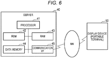
- FIG. 6 is a block diagram illustrating a configuration example of a server 40 as a barcode generation device according to a modification example of the first embodiment.
- the server 40 communicates with a display device such as a portable terminal and generates a plurality of barcode images in which noise is superimposed in response to a request from the display device. Further, the server 40 sequentially displays the plurality of generated barcode images on the display device. That is, the server 40 functions as a barcode generation device and controls the display of a barcode image on the display device.
- the server 40 includes a processor 41, a read-only memory (ROM) 42, a random access memory (RAM) 43, a data memory 44, and a communication interface (I/F) 45.
- the processor 41 is connected to the ROM 42, the RAM 43, the data memory 44, and the communication interface 45.
- the processor 41 performs various processes by executing programs.
- the processor 41 is, for example, a central processing unit (CPU).
- the processor 41 realizes various processing functions by executing programs stored in the ROM 41 or the data memory 44.
- the processor 41 communicates with the display device via the communication interface 45 by executing a communication program.
- the processor 41 generates an image of a barcode to be displayed on the display of the display device by executing a barcode generation program.
- the processor 41 displays the generated barcode image on the display of the display device by executing a barcode display program.
- the ROM 42 is a non-volatile memory.
- the ROM 42 stores programs and data.
- the ROM 42 stores programs such as an operating system, middleware, and applications.
- the ROM 42 may store data which is referred to when the processor 41 performs various processes.
- the RAM 43 stores working data.
- the RAM 43 is a memory used as a so-called work area.
- the RAM 43 appropriately stores data which is referred to or data which is temporarily used when the processor 41 performs various processes.
- the data memory 44 is a rewritable nonvolatile memory.
- the data memory 44 is configured with, for example, a memory (storage device) such as an electric erasable programmable read-only memory (EEPROM) (registered trademark), a hard disk drive (HDD), a solid-state drive (SSD), and a memory card.
- EEPROM electric erasable programmable read-only memory
- HDD hard disk drive
- SSD solid-state drive
- memory card a memory card
- the communication interface 45 is an interface (network interface) for communicating with an external device via a network.
- the communication interface 45 is an interface that communicates with the display device 50 via the network.
- the communication interface 45 is an example of an interface that receives an instruction to display barcode requested from the display device 50.
- the display device 50 communicates with the server 40 via the network.
- the display device 50 is a device that displays a barcode image supplied from the server 40.
- the display device 50 supplies display of a barcode to the server 40 in response to an operation or the like from the user.
- the display device 50 may be a device capable of requesting the server 40 to display the barcode and displaying the barcode image from the server as a barcode image read with the barcode reader.
- the display device 50 is a portable terminal such as a smartphone, a mobile phone, or a tablet PC.
- Programs that are executed by the processor 41 of the server 40 are stored in the ROM 42 or the data memory 44.
- the programs that are executed by the processor 41 are an operating system (OS), a barcode display program, and a barcode generation program, as exemplified in FIG. 2 .
- OS operating system
- barcode display program barcode display program
- barcode generation program as exemplified in FIG. 2 .
- the OS is a program that manages a basic operation of the server 40.
- the processor 41 can execute a program that is based on the OS by executing the OS.
- the barcode display program is a program for displaying a barcode on the display device 50.
- the barcode generation program is a program for generating a barcode displayed on the display device 50.
- the server 40 stores a program for communicating with the display device 50, a program for operating in response to a command from the display device 50, and the like in the RAM 42 or the data memory 44.
- the server 40 generates a plurality of barcode images (display images) in which noise is superimposed on a basic barcode in response a request from the display device 50.
- the server 40 sequentially displays the plurality of generated barcode images repeatedly on the display of the display device 50. That is, the plurality of barcode images generated by the server 40 are barcode images in which noise is superimposed at different positions on the basic barcode, as exemplified in FIG. 3 .
- the server 40 sequentially displays the plurality of barcode images in which noise is superimposed on the display device 50 so that the scanned images illustrated in FIG. 4 can be read by the barcode reader.
- the server 40 checks whether there is misreading in the plurality of barcode images in which noise is superimposed and an image in which the plurality of barcode images are combined.
- the server 40 checks whether there is misreading in the individual barcode images and the combined image in which the plurality of barcode images 31A are combined.
- the server 40 prevents misreading due to a barcode image displayed on the display device 50.
- FIG. 7 is a flowchart illustrating an operation example of the barcode display process in the server 40.
- the processor 41 of the server 40 receives a barcode display request from the display device 50 connected via the network (ACT20).
- ACT20 a command for the barcode display request is received from the display device 50 (YES in ACT20)
- the processor 41 generates a basic barcode that is displayed on the display device 50 and is read by the barcode reader (ACT21).
- the processor 41 acquires information regarding the barcode to be displayed (information indicated by the basic barcode) in response to the request from the display device 50 and generates the basic barcode from the acquired information.
- the information indicated by the basic barcode may be information stored in the data memory 44 or may be information generated through arithmetic processing by the processor 41.
- the processor 41 When the basic barcode is generated, the processor 41 generates a plurality of barcode images (display images) by superimposing noise at different positions on the basic barcode (ACT22). After generating the plurality of barcode images in which noise is superimposed, the processor 41 checks whether there is a possibility of misreading in the generated individual barcode images (ACT23) . When it is determined that there is a possibility of the misreading in any barcode image (YES in ACT23), the process returns to ACT22 and the processor 41 generates a plurality of barcode images in which noise is superimposed at different positions.
- the processor 41 determines whether there is a possibility of misreading in an image (scanned image) when the plurality of barcode images are combined and read (ACT24). When it is determined that there is a possibility of misreading in any scanned image (YES in ACT24), the process returns to ACT22 and the processor 41 generates a plurality of barcode images in which noise is superimposed at different positions.
- the processor 41 sequentially displays the plurality of barcode images on the display of the display device 50 (ACT25) .
- the processor 41 supplies the barcode image (first display image) 31A and the barcode image (second display image) 31B to be displayed as a barcode to the display device 50.
- the processor 41 informs the display device 50 of timings at which the barcode images 31A and 31B are alternately displayed (display switch timings).
- the processor 41 informs the display device 50 of the display switch timings at which the barcode reader can continuously scan a region on the right side of the barcode image 31A and a region on the left side of the barcode image 31B.
- the display device 50 alternately displays the barcode images 31A and 31B on the display 17 at the informed timings.
- the processor 41 sequentially displays the plurality of barcode images on the display device 50 and receives an instruction to end the display of the barcode (ACT26). For example, the processor 41 receives a display end notification from the display device 50 while sequentially displaying the plurality of barcode images. The processor 41 may end the display of the plurality of barcode images on the display device 50 at a predetermined time from the display start. When it is determined that the display of the barcode does not end (NO in ACT26), the process returns to ACT25 and the processor 41 continues to display the plurality of barcode images. Conversely, when it is determined that the display of the barcode ends (YES in ACT26), the processor 41 ends the display of the barcode on the display device 50.
- the server as the barcode generation device communicates with the display device and generates a basic barcode in response to the request from the display device.
- the server generates the plurality of barcodes in which noise is superimposed at different positions on the basic barcode.
- the server determines whether there is misreading when the barcode reader scans a screen on which the plurality of barcodes generated with the superimposed noise are sequentially displayed. When it is determined that there is no misreading, the server sequentially displays the plurality of barcodes generated with the superimposed noise on the display device.
- a server as a barcode generation device capable of preventing illegal use of a barcode displayed on the display device while reducing the risk of misreading.
- a barcode generation device is realized as a portable terminal having the configuration described in the first embodiment. That is, the barcode generation device according to the second embodiment is assumed to be the portable terminal 10 that has the configuration illustrated in FIG. 1 , as described in the first embodiment. Therefore, in the second embodiment, the configuration of the portable terminal 10 as a barcode generation device will not be described in detail.
- an application program stored in the ROM 12 or the data memory 14 of the portable terminal 10 according to the second embodiment is different from that of the first embodiment.
- the ROM 12 of the portable terminal 10 according to the second embodiment stores an application program for realizing a process to be described below together with an OS.
- the portable terminal 10 splits a basic barcode into portions that are singly undecodable and generates a group of barcodes that are split (split barcodes).
- the portable terminal 10 sequentially displays images of the split barcodes on the display 17.
- the barcode reader is assumed to have a function capable of collecting barcodes read for each thin partial piece and decoding the partial pieces as one barcode (a split reading function) .
- the split reading function is equipped in a general barcode reader.
- the split reading function is, for example, a function of reading a barcode attached to a location at which reading is difficult, such as a baglike article.
- the barcode reader that has the split reading function can read split barcodes sequentially displayed on the display 17 and combine the split barcodes to decode all the barcodes.
- the barcode reader that reads images of barcodes displayed on the display 17 is assumed to have the split reading function in the description.
- FIG. 8 is a diagram illustrating a first example of split barcodes 81 and 82 generated from a basic barcode 80.
- FIG. 8 illustrates an example in which a basic barcode 80 is split into two split barcodes 81 and 82.
- the example illustrated in FIG. 8 is an example of 2-splitting by half segments.
- the half segment is a segment including a center bar and one character from a guard bar.
- the split barcode 81 is configured to include a region on the left side of the basic barcode 80.
- the split barcode 82 is configured to include a region on the right side of the basic barcode 80.
- the spit barcodes 81 and 82 are configured so that partial regions overlap.
- the two split barcodes 81 and 82 are generated so that the spit barcodes overlap by one character including the center bar before and after the center bar.
- FIG. 9 is a diagram illustrating a second example of split barcodes 91, 92, and 93 generated from a basic barcode 90.
- FIG. 9 illustrates an example in which the basic barcode 90 is split into three split barcodes 91, 92, and 93.
- the example illustrated in FIG. 9 is an example of 3-splitting by partial segments.
- the partial segment is a segment of a guard bar or several characters including a center bar.
- the split barcode 91 is configured to include a region on the left side of the basic barcode 90.
- the split barcode 92 is configured to include a region near the middle of the basic barcode 90.
- the split barcode 93 is configured to include a region on the right side of the basic barcode 90.
- the split barcodes 91 and 92 are configured so that partial regions overlap. In the specific example illustrated in FIG. 9 , the split barcodes 91 and 92 are configured to overlap by one character in the left data characters. The split barcodes 92 and 93 are configured so that partial regions overlap. In the specific example illustrated in FIG. 9 , the split barcodes 92 and 93 are configured to overlap by one character in the right data characters.
- the plurality of split barcodes generated from the basic barcode is configured so that adjacent partial regions of the basic barcode mutually overlap.
- the regions in which the split barcodes mutually overlap can appropriately be set.
- the individual split barcodes may be configured to be singly undecodable. Therefore, the split barcodes of the adjacent regions may be configured to overlap in the regions by a plurality of characters.
- the split barcodes are configured to be each singly undecodable. Therefore, the split barcodes displayed on the display 17 by the portable terminal 10 are singly undecodable.
- images (split barcodes) displayed on the display cannot be used illegally although the images are captured. Since the split barcodes are cuts from the basic barcode and are generated without superimposing noise, it is possible to reduce the risk of misreading in the individual split barcodes .
- FIG. 10 is a flowchart illustrating an operation example of the barcode display process in the portable terminal 10 according to the second embodiment.
- the processor 11 of the portable terminal 10 generates a basic barcode which is read by the barcode reader when a barcode is displayed on the display 17 (ACT111).
- the processor 11 splits the basic barcode to generate a plurality of split barcodes (split images) (ACT112) .
- the processor 11 splits the basic barcode into a plurality of regions to generate the split barcodes including overlap portions with regions adjacent to the split regions, and a splitting number may be within a range which can be read by the barcode reader. For example, when the splitting number is 2, the processor 11 splits the basic barcode into two half segments to generate two split barcodes. When the splitting number is 3, the processor 11 splits the basic barcode into three partial segments to generate three split barcode images.
- the processor 11 sequentially displays the images of the plurality of split barcodes on the display 17 (ACT113).
- the split barcodes sequentially displayed on the display are sufficient as long as respective images can be sequentially read by the barcode reader. Accordingly, the processor 11 displays the images of the respective split barcodes so as to be sequentially read by the barcode reader.
- the processor 11 receives an instruction to end the display of the barcode (ACT114). Until the instruction to end the display of the barcode is received (NO in ACT114), the processor 11 continues the sequential display control of the plurality of split barcode images. Conversely, when the instruction to end the display of the barcode is received (YES in ACT114), the processor 11 ends the series of the barcode display process. For example, the processor 11 receives an instruction to end the display of the barcode as a user instruction detected by the touch sensor 18. The processor 11 may set a display time of the barcode and determine the end of the display of the barcode at a time point at which the display time elapses from display start.
- the portable terminal as a barcode generation device generates a plurality of split barcodes obtained by splitting the basic barcode so that the partial regions overlap.
- the portable terminal sequentially displays the plurality of split barcodes on the display.
- a barcode generation device is realized as a server having the configuration described in the modification example of the first embodiment. That is, the barcode generation device according to the modification example of the second embodiment is assumed to be the server 40 that has the configuration illustrated in FIG. 6 described in the first embodiment. Therefore, in the modification example of the second embodiment, the configuration of the server 40 as the barcode generation device will not be described in detail.
- an application program stored in the ROM 42 or the data memory 44 of the server 40 according to the modification example of the second embodiment is different from that of the modification example of the first embodiment.
- the ROM 42 of the server 40 according to the modification example of the second embodiment stores an application program for realizing a process to be described below together with an OS.
- the processor 41 of the server 40 generates a plurality of split barcode images (display images) generated by splitting a basic barcode in response to a request from the display device 50.
- the processor 41 of the server 40 sequentially displays the generated split barcode images on the display of the display device 50 repeatedly.
- the plurality of split barcode images generated by the processor 41 may be the barcode images exemplified in FIG. 8 or 9 or the like.
- FIG. 11 is a flowchart illustrating an operation example of the barcode display process in the server 40.
- the processor 41 of the server 40 receives a barcode display request from the display device 50 connected via the network (ACT120).
- ACT120 a command for the barcode display request is received from the display device 50 (YES in ACT120)
- the processor 41 generates a basic barcode that is displayed on the display device 50 and is read by the barcode reader (ACT121) .
- the processor 41 acquires information regarding the barcode to be displayed (information indicated by the basic barcode) in response to the request from the display device 50 and generates the basic barcode from the acquired information.
- the information indicated by the basic barcode may be information stored in the data memory 44 or may be information generated through arithmetic processing by the processor 41.
- the processor 41 splits the basic barcode to generate a plurality of split barcode images (display images) (ACT122). After generating the plurality of split barcode images, the processor 41 sequentially displays the plurality of split barcode images on the display of the display device 50 (ACT123) . For example, the processor 41 displays the plurality split barcode images on the display device 50 by sequentially delivering the split barcode images to the display device 50. The processor 41 may collectively supply the plurality of split barcode image to the display device 50 and the display device 50 may sequentially display the split barcode images.
- the processor 41 sequentially displays the plurality of barcode images on the display device 50 and receives an instruction to end the display of the barcode (ACT124). For example, the processor 41 receives an end command requesting a display end from the display device 50 while sequentially displaying the plurality of barcode images. When it is determined that the display of the barcode does not end (NO in ACT124), the process returns to ACT123 and the processor 41 continues the display of the plurality of barcode images. Conversely, when it is determined that the display of the barcode ends (YES in ACT124), the processor 41 ends the display of the barcode on the display device 50.
- the server as the barcode generation device communicates with the display device and generates a basic barcode in response to the request from the display device.
- the server generates a plurality of split barcodes obtained by splitting the basic barcode so that partial regions overlap.
- the server sequentially displays the plurality of split barcodes on the display device.
Landscapes
- Engineering & Computer Science (AREA)
- Physics & Mathematics (AREA)
- General Physics & Mathematics (AREA)
- Theoretical Computer Science (AREA)
- Health & Medical Sciences (AREA)
- Electromagnetism (AREA)
- General Health & Medical Sciences (AREA)
- Toxicology (AREA)
- Artificial Intelligence (AREA)
- Computer Vision & Pattern Recognition (AREA)
- Computer Networks & Wireless Communication (AREA)
- Quality & Reliability (AREA)
- Business, Economics & Management (AREA)
- Signal Processing (AREA)
- Optics & Photonics (AREA)
- Accounting & Taxation (AREA)
- Strategic Management (AREA)
- General Business, Economics & Management (AREA)
- Controls And Circuits For Display Device (AREA)
- User Interface Of Digital Computer (AREA)
Abstract
According to one embodiment, a barcode generation device includes an interface and a processor. The interface receives a barcode display instruction. The processor generates a basic barcode in response to the display instruction received by the interface, generates a plurality of barcodes in which noise is superimposed at different positions on the basic barcode, determines whether there is misreading in an image scanned by a barcode reader on a screen on which the plurality of barcodes are sequentially displayed, and sequentially displays the plurality of barcodes on a display device when it is determined that there is no misreading.
Description
- Embodiments described herein relate generally to a barcode generation device and a barcode generation method.
- In recent years, solutions using barcodes displayed by portable terminals such as smartphones as substitutes of coupons or entrance tickets have been widespread. However, barcodes displayed on displays have a risk of illegal use or distribution by copy or the like using capturing functions on display screens or digital cameras.
-
-
FIG. 1 is a block diagram illustrating a configuration example of a portable terminal serving as a barcode generation device according to a first embodiment; -
FIG. 2 is a diagram illustrating an example of a program stored in a memory of the barcode generation device according to the first embodiment; -
FIG. 3 is a diagram illustrating examples of a plurality of barcode images generated by the barcode generation device according to the first embodiment; -
FIG. 4 is a diagram illustrating examples of display control on the plurality of barcode images generated by the barcode generation device and scanned images by a barcode reader according to the first embodiment; -
FIG. 5 is a flowchart illustrating an operation example of a barcode display process by a portable terminal serving as the barcode generation device according to the first embodiment; -
FIG. 6 is a block diagram illustrating a configuration example of a server serving as the barcode generation device according to a modification example of the first embodiment; -
FIG. 7 is a flowchart illustrating an operation example of a barcode display process by a server serving as the barcode generation device according to a modification example of the first embodiment; -
FIG. 8 is a diagram illustrating a first example of a plurality of split barcodes generated by a barcode generation device according to a second embodiment; -
FIG. 9 is a diagram illustrating a second example of a plurality of split barcodes generated by a barcode generation device according to the second embodiment; -
FIG. 10 is a flowchart illustrating an operation example of a barcode display process by a portable terminal serving as the barcode generation device according to the second embodiment; and -
FIG. 11 is a flowchart illustrating an operation example of a barcode display process by a server serving as the barcode generation device according to a modification example of the second embodiment. - Embodiments provide a barcode generation device and a barcode generation method which are capable of preventing the illegal use of a barcode.
- In general, according to one embodiment, a barcode generation device includes an interface and a processor. The interface receives a barcode display instruction. The processor generates a basic barcode in response to the display instruction received by the interface, generates a plurality of barcodes in which noise is superimposed at different positions on the basic barcode, determines whether there is misreading in an image scanned by a barcode reader on a screen on which the plurality of barcodes are sequentially displayed, and sequentially displays the plurality of barcodes on a display device when it is determined that there is no misreading.
- Preferably, to determine whether there is the misreading comprises to determine whether there is misreading in each of images of a plurality of barcodes in which the noise is superimposed.
- Preferably, to determine whether there is the misreading comprises to determine whether there is misreading in a combined image which is obtained when the plurality of sequentially displayed barcodes are scanned.
- Preferably, the basic barcode is generated so as to be decodable by a barcode reader.
- Preferably, the plurality of barcodes is generated so as to be undecodable by a barcode reader.
- Preferably, the display device is a smartphone.
- The present invention further relates to a barcode generation device, comprising: an interface configured to receive a barcode display instruction; and
a processor configured to generate a basic barcode in response to the barcode display instruction received by the interface, generate a split barcode image group in which the basic barcode is split into a plurality of images that are singly undecodable, and sequentially display the split barcode image group on a display device. - Preferably the split barcode image group comprises an image group in which the basic barcode is split so that partial regions overlap between adjacent regions.
- Preferably, the basic barcode is generated so as to be decodable by a barcode reader.
- Preferably, the split barcode image group is generated so as to be undecodable by a barcode reader.
- Preferably, the display device is a smartphone.
- The present invention also relates to a barcode generation method, comprising:
- generating, by a processor, a basic barcode in response to a barcode display instruction received;
- generating, by a processor, a plurality of barcodes in which noise is superimposed at different positions on the basic barcode;
- determining, by a processor, whether there is a misreading in an image scanned by a barcode reader on a screen on which the plurality of barcodes are sequentially displayed; and
- sequentially displaying the plurality of barcodes on a display device when a determination indicates that there is no misreading.
- The barcode generation method may further comprise:
- determining, by a processor, whether there is a misreading in each of images of a plurality of barcodes in which the noise is superimposed, and
- determining, by a processor, whether there is a misreading in a combined image which is obtained when the plurality of sequentially displayed barcodes are scanned.
- Preferably, the basic barcode is generated so as to be decodable by a barcode reader.
- Preferably, the plurality of barcodes is generated so as to be undecodable by a barcode reader.
- Preferably, the display device is a smartphone.
- The present invention further relates to a barcode generation method, comprising:
- generating, by a processor, a basic barcode in response to a barcode display instruction;
- generating, by a processor, a split barcode image group in which the basic barcode is split into a plurality of images that are singly undecodable; and
- sequentially display the split barcode image group on a display device.
- Preferably, the split barcode image group comprises an image group in which the basic barcode is split so that partial regions overlap between adjacent regions.
- Preferably, the basic barcode is generated so as to be decodable by a barcode reader.
- Preferably, the split barcode image group is generated so as to be undecodable by a barcode reader.
- Preferably, the display device is a smartphone.
- Hereinafter, embodiments will be described with reference to the drawings.
- A barcode generation device according to each embodiment generates a barcode displayed on a display of a portable terminal such as a smartphone, a mobile phone, or a tablet PC. The barcode generation device may be a portable terminal or a computer such as a server capable of communicating with a portable terminal. In the first and second embodiments described below, a case of a portable terminal and a case of a server as the barcode generation device will be described.
-
FIG. 1 is a block diagram illustrating a configuration example of aportable terminal 10 serving as a barcode generation device according to the first embodiment. - As illustrated in
FIG. 1 , theportable terminal 10 includes aprocessor 11, a read-only memory (ROM) 12, a random access memory (RAM) 13, adata memory 14, an interface (panel interface) 15, and atouch panel 16. Theprocessor 11 is connected to theROM 12, theRAM 13, thedata memory 14, and thepanel interface 15. Thetouch panel 16 includes adisplay 17 and atouch sensor 18. Thetouch panel 16 is connected to theprocessor 11 via thepanel interface 15. - The
processor 11 performs various processes by executing programs. Theprocessor 11 is, for example, a central processing unit (CPU). Theprocessor 11 realizes various processing functions by executing programs stored in the ROM 21 or thedata memory 14. For example, theprocessor 11 generates a barcode image to be displayed on the display by executing a barcode generation program. Theprocessor 11 displays the generated barcode image on thedisplay 17 by executing a barcode display program. - The
ROM 12 is a non-volatile memory. TheROM 12 stores programs and data. For example, theROM 12 stores programs such as an operating system, middleware, and applications. TheROM 12 may store data which is referred to when theprocessor 11 performs various processes. - The
RAM 13 stores working data. TheRAM 13 is a memory used as a so-called work area. TheRAM 13 appropriately stores data which is referred to or data which is temporarily used when theprocessor 11 performs various programs. - The
data memory 14 is a rewritable nonvolatile memory. Thedata memory 14 is configured with, for example, a memory (storage device) such as an electric erasable programmable read-only memory (EEPROM) (registered trademark), a hard disk drive (HDD), a solid-state drive (SSD), and a memory card. - The
panel interface 15 is connected to thetouch panel 16. Thetouch panel 16 is an example of a display device connected to an interface in theportable terminal 10. In the example illustrated inFIG. 1 , thetouch panel 16 includes thedisplay 17 as a display unit and thetouch sensor 18 as an operation unit. The display device connected to the interface in theportable terminal 10 may be a display device capable of displaying a barcode image or may not be a touch panel that includes a touch sensor. - The
touch interface 15 connects theprocessor 11 to thedisplay 17 and thetouch sensor 18 in thetouch panel 16. Theprocessor 11 controls an image displayed on thedisplay 17 via thepanel interface 15. Theprocessor 11 acquires an input signal (operation signal) detected by thetouch sensor 18 via thepanel interface 15. Thepanel interface 15 is an example of an interface that receives a barcode display instruction input on thetouch panel 16. - Next, a program executed by the
processor 11 of theportable terminal 10 will be described. - Programs that are executed by the
processor 11 are installed in theROM 12 or thedata memory 14. For example, theprocessor 11 executes a program of an operating system (OS) that manages a basic operation of theportable terminal 10. Theprocessor 11 executes various application programs after the OS is executed. -
FIG. 2 is a schematic diagram illustrating an example of a program group stored in theROM 12 of theportable terminal 10 according to the first embodiment. - As illustrated in
FIG. 2 , theROM 12 stores various programs that are executed by theprocessor 11. In the example illustrated inFIG. 2 , theROM 12 stores an operating system (OS), a barcode display program, and a barcode generation program. The OS is a program that manages a basic operation of theportable terminal 10. Theprocessor 11 can execute an application program that is based on the OS by executing the OS. For example, the barcode display program and the barcode generation program may be generated as application programs operated on the OS. - The barcode display program and the barcode generation program are an application program for realizing operations described below according to the first embodiment.
- The barcode display program is a program for displaying barcodes on a display device. The
processor 11 realizes display control of barcode images described below by executing the barcode display program. - The barcode generation program is a program for generating barcodes. The
processor 11 generates a basic barcode described below and generates a plurality of barcode images for display by executing the barcode generation program. - Here, the programs illustrated in
FIG. 2 may be stored in a memory so as to be executed by theprocessor 11 or may be stored in a memory such as thedata memory 14 other than theROM 12. For example, the OS may be stored in theROM 12 and the barcode display program and the barcode generation program may be stored in thedata memory 14. - Next, barcode images generated by the
portable terminal 10 as a barcode generation device according to the first embodiment will be described. - The
portable terminal 10 according to the first embodiment generates a plurality of barcode images (display images) in which noise is superimposed on the basic barcode and sequentially displays the plurality of barcode images repeatedly. A scanner of a barcode reader reads the plurality of sequentially displayed display images as images combined at scan timings. The barcode reader can read a barcode in which regions without noise are combined when the scan timings are correct. Thus, theportable terminal 10 can display the barcode image in which the individual display images are undecodable and cause the barcode reader to read the barcode without noise. -
FIG. 3 is a diagram illustrating examples of a plurality of barcode images (display images) 31A and 31B generated by superimposing noise in abasic barcode 30. - The
barcode image 31A is a first display image generated by superimposing noise on one portion on the left side of thebasic barcode 30. Thebarcode image 31B is a second display image generated by superimposing noise on one portion on the right side of thebasic barcode 30. When a portion without noise in thebarcode image 31A and a portion without noise in thebarcode image 31B are scanned, thebasic barcode 30 without noise is read. -
FIG. 4 is a diagram illustrating a relationship between display control of the plurality ofbarcode images images 32a to 32d which are scan results. - The
portable terminal 10 alternately displays thebarcode images display 17. A scanner (barcode reader) that scans a display screen of thedisplay 17 in a predetermined direction (direction a) reads thebarcode images display 17 and a scan timing. -
FIG. 4 illustrates examples of scannedimages 32a to 32d obtained by the barcode reader (the scanner). - The scanned
image 32a is an image in which noise n1 on the left side is superimposed on thebasic barcode 30. The scannedimage 32a is a result obtained when only thebarcode image 31A is read. The scannedimage 32a is undecodable by the barcode reader due to the noise n1. - The scanned
image 32b is an image in which noise n2 on the right side is superimposed on thebasic barcode 30. The scannedimage 32b is a result obtained when only thebarcode image 31B is read. The scannedimage 32b is undecodable by the barcode reader due to the noise n2. - The scanned
image 32c is an image in which the noise n1 on the left side and the noise n2 on the right side are superimposed on thebasic barcode 30. The scannedimage 32c is a result read by combining a region including noise in thebarcode image 31A (a region on the left side of thebarcode image 31A) and a region including noise in the barcode image 32B (a region on the right side of thebarcode image 31B) . The scannedimage 32c is undecodable by the barcode reader due to the noise n1 and the noise n2. - The scanned
image 32d is an image in which no noise is included in thebasic barcode 30. The scannedimage 32d is a result read by combining a region including no noise in thebarcode image 31A (a region on the right side of thebarcode image 31A) and a region including no noise in the barcode image 32B (a region on the left side of thebarcode image 31B) . Since the scannedimage 32d includes no noise and is the read basic barcode, the scannedimage 32d is decodable by the barcode reader. - The barcode reader performs scanning again when the scanned
images image 32d (that is, a decodable barcode) is read as a barcode image without noise. As a result, the barcode reader can read a correct barcode (decodable barcode) from the barcode image in which two pieces of noise alternately displayed on thedisplay 17 are superimposed. Theportable terminal 10 alternately displays the plurality of barcode images (display images) 31A and 31B on thedisplay 17 so that the barcode reader can read the scannedimage 32d. - In general, a decoded result of the scanned image is determined with check digits included in the barcode. Therefore, when noise triggers an incorrect reading even in the scanned image with noise, there is a possibility that check digits are read at a low probability. For example, in WPC, C/D matches and reading is achieved at a probability of 1/10 even in a misreading result in some cases. That is, when random noise is simply added to the basic barcode, there is a possibility of the barcode reader performing misreading in an image with noise.
- Therefore, the barcode generation device according to the first embodiment checks whether there is misreading in a plurality of barcode images in which noise is superimposed and an image in which the plurality of barcode images are combined. The
portable terminal 10 checks whether there is misreading in thebarcode image 31A, thebarcode image 31B, and a combined image in which thebarcode images display 17, it is possible to prevent misreading. - Next, a barcode display process in the
portable terminal 10 as a barcode generation device according to the first embodiment will be described. -
FIG. 5 is a flowchart illustrating an operation example of the barcode display process in theportable terminal 10. - The
processor 11 of theportable terminal 10 generates a basic barcode which is read by the barcode reader when a barcode is displayed on the display 17 (ACT11). For example, theprocessor 11 acquires information (barcode information) which is read by the barcode reader. For example, the barcode information may be information stored in thedata memory 14 or the like, may be information acquired from an external device or the like, or may be information generated through arithmetic processing by theprocessor 11. - When the basic barcode is generated, the
processor 11 generates a plurality of barcode images (display images) by superimposing noise on the basic barcode (ACT12). Theprocessor 11 generates the plurality of barcode images in which noise is superimposed at different positions on the basic barcode in a scanning direction of the barcode reader. For example, in the example illustrated inFIG. 3 , theprocessor 11 generates thebarcode image 31A in which noise is superimposed in a region on the left side and thebarcode image 31B in which noise is superimposed in a region on the right side on thebasic barcode 30. - After the plurality of images in which the noise is superimposed are generated, the
processor 11 checks whether there is a possibility of misreading in the generated individual barcode images (ACT13) . When it is determined that there is a possibility of the misreading in any barcode image (YES in ACT13), the process returns to ACT12 and theprocessor 11 generates a plurality of barcode images in which noise is superimposed at different positions. - When it is determined that there is no misreading in any barcode image (NO in ACT13), the
processor 11 determines whether there is a possibility of misreading in an image (scanned image) when the plurality of barcode images are combined and read (ACT14). When it is determined that there is a possibility of misreading in any scanned image (YES in ACT14), the process returns to ACT12 and theprocessor 11 generates a plurality of barcode images in which noise is superimposed at different positions. - When it is determined that there is no misreading in the scanned image in which the plurality of barcode images are combined (NO in ACT14), the
processor 11 performs display control such that the plurality of barcode images are sequentially displayed on the display 17 (ACT15) . For example, as illustrated inFIG. 4 , thebarcode image 31A as a first display image and thebarcode image 31B as a second display image are alternately displayed on thedisplay 17. Theprocessor 11 sequentially switches and displays thebarcode images barcode image 31A and the region on the left side of thebarcode image 31B. - When the plurality of barcode images is sequentially displayed on the
display 17, theprocessor 11 receives an instruction to end the display of the barcode (ACT16) . Until the instruction to end the display of the barcode is received (NO in ACT16), theprocessor 11 continues the display control of the plurality of barcode images. Conversely, when the instruction to end the display of the barcode is received (YES in ACT16), theprocessor 11 ends the series of the barcode display process. For example, theprocessor 11 may receive an instruction to end the display of the barcode as an instruction from a user detected by thetouch sensor 18. Theprocessor 11 may set a display time of the barcode and determine the end of the display of the barcode at a time point at which the display time elapses from display start. - As described above, the portable terminal as the barcode generation device according to the first embodiment generates the plurality of barcodes in which noise is superimposed at different positions on the basic barcode. The portable terminal determines whether there is misreading when the barcode reader scans a screen on which the plurality of barcodes generated with the superimposed noise are sequentially displayed. When it is determined that there is no misreading, the portable terminal sequentially displays the plurality of barcodes generated with the superimposed noise on the screen.
- Thus, according to the first embodiment, it is possible to provide a portable terminal as the barcode generation device capable of preventing illegal use of a barcode displayed on a screen while reducing the risk of misreading.
- Next, a modification example of the above-described first embodiment will be described.
-
FIG. 6 is a block diagram illustrating a configuration example of aserver 40 as a barcode generation device according to a modification example of the first embodiment. - In the modification example of the first embodiment, the
server 40 communicates with a display device such as a portable terminal and generates a plurality of barcode images in which noise is superimposed in response to a request from the display device. Further, theserver 40 sequentially displays the plurality of generated barcode images on the display device. That is, theserver 40 functions as a barcode generation device and controls the display of a barcode image on the display device. - As illustrated in
FIG. 6 , theserver 40 includes aprocessor 41, a read-only memory (ROM) 42, a random access memory (RAM) 43, adata memory 44, and a communication interface (I/F) 45. Theprocessor 41 is connected to theROM 42, theRAM 43, thedata memory 44, and thecommunication interface 45. - The
processor 41 performs various processes by executing programs. Theprocessor 41 is, for example, a central processing unit (CPU). Theprocessor 41 realizes various processing functions by executing programs stored in theROM 41 or thedata memory 44. For example, theprocessor 41 communicates with the display device via thecommunication interface 45 by executing a communication program. Theprocessor 41 generates an image of a barcode to be displayed on the display of the display device by executing a barcode generation program. Theprocessor 41 displays the generated barcode image on the display of the display device by executing a barcode display program. - The
ROM 42 is a non-volatile memory. TheROM 42 stores programs and data. For example, theROM 42 stores programs such as an operating system, middleware, and applications. TheROM 42 may store data which is referred to when theprocessor 41 performs various processes. - The
RAM 43 stores working data. TheRAM 43 is a memory used as a so-called work area. TheRAM 43 appropriately stores data which is referred to or data which is temporarily used when theprocessor 41 performs various processes. - The
data memory 44 is a rewritable nonvolatile memory. Thedata memory 44 is configured with, for example, a memory (storage device) such as an electric erasable programmable read-only memory (EEPROM) (registered trademark), a hard disk drive (HDD), a solid-state drive (SSD), and a memory card. - The
communication interface 45 is an interface (network interface) for communicating with an external device via a network. In the configuration example illustrated inFIG. 6 , thecommunication interface 45 is an interface that communicates with thedisplay device 50 via the network. Thecommunication interface 45 is an example of an interface that receives an instruction to display barcode requested from thedisplay device 50. - The
display device 50 communicates with theserver 40 via the network. Thedisplay device 50 is a device that displays a barcode image supplied from theserver 40. Thedisplay device 50 supplies display of a barcode to theserver 40 in response to an operation or the like from the user. Thedisplay device 50 may be a device capable of requesting theserver 40 to display the barcode and displaying the barcode image from the server as a barcode image read with the barcode reader. For example, thedisplay device 50 is a portable terminal such as a smartphone, a mobile phone, or a tablet PC. - Programs that are executed by the
processor 41 of theserver 40 are stored in theROM 42 or thedata memory 44. The programs that are executed by theprocessor 41 are an operating system (OS), a barcode display program, and a barcode generation program, as exemplified inFIG. 2 . - The OS is a program that manages a basic operation of the
server 40. Theprocessor 41 can execute a program that is based on the OS by executing the OS. - The barcode display program is a program for displaying a barcode on the
display device 50. The barcode generation program is a program for generating a barcode displayed on thedisplay device 50. Theserver 40 stores a program for communicating with thedisplay device 50, a program for operating in response to a command from thedisplay device 50, and the like in theRAM 42 or thedata memory 44. - Next, a barcode image generated by the
server 40 as a barcode generation device according to a modification example of the first embodiment will be described. - The
server 40 according to the modification example of the first embodiment generates a plurality of barcode images (display images) in which noise is superimposed on a basic barcode in response a request from thedisplay device 50. Theserver 40 sequentially displays the plurality of generated barcode images repeatedly on the display of thedisplay device 50. That is, the plurality of barcode images generated by theserver 40 are barcode images in which noise is superimposed at different positions on the basic barcode, as exemplified inFIG. 3 . Theserver 40 sequentially displays the plurality of barcode images in which noise is superimposed on thedisplay device 50 so that the scanned images illustrated inFIG. 4 can be read by the barcode reader. - As in the above-described portable terminal, the
server 40 checks whether there is misreading in the plurality of barcode images in which noise is superimposed and an image in which the plurality of barcode images are combined. Theserver 40 checks whether there is misreading in the individual barcode images and the combined image in which the plurality ofbarcode images 31A are combined. Thus, theserver 40 prevents misreading due to a barcode image displayed on thedisplay device 50. - Net, a barcode display process in the
server 40 serving as the barcode generation device according to the modification example of the first embodiment will be described. -
FIG. 7 is a flowchart illustrating an operation example of the barcode display process in theserver 40. - The
processor 41 of theserver 40 receives a barcode display request from thedisplay device 50 connected via the network (ACT20). When a command for the barcode display request is received from the display device 50 (YES in ACT20), theprocessor 41 generates a basic barcode that is displayed on thedisplay device 50 and is read by the barcode reader (ACT21). Theprocessor 41 acquires information regarding the barcode to be displayed (information indicated by the basic barcode) in response to the request from thedisplay device 50 and generates the basic barcode from the acquired information. The information indicated by the basic barcode may be information stored in thedata memory 44 or may be information generated through arithmetic processing by theprocessor 41. - When the basic barcode is generated, the
processor 41 generates a plurality of barcode images (display images) by superimposing noise at different positions on the basic barcode (ACT22). After generating the plurality of barcode images in which noise is superimposed, theprocessor 41 checks whether there is a possibility of misreading in the generated individual barcode images (ACT23) . When it is determined that there is a possibility of the misreading in any barcode image (YES in ACT23), the process returns to ACT22 and theprocessor 41 generates a plurality of barcode images in which noise is superimposed at different positions. - When it is determined that there is no misreading in any barcode images (NO in ACT23), the
processor 41 determines whether there is a possibility of misreading in an image (scanned image) when the plurality of barcode images are combined and read (ACT24). When it is determined that there is a possibility of misreading in any scanned image (YES in ACT24), the process returns to ACT22 and theprocessor 41 generates a plurality of barcode images in which noise is superimposed at different positions. - When it is determined that there is no misreading in the scanned image in which the plurality of barcode images are combined (NO in ACT24), the
processor 41 sequentially displays the plurality of barcode images on the display of the display device 50 (ACT25) . For example, theprocessor 41 supplies the barcode image (first display image) 31A and the barcode image (second display image) 31B to be displayed as a barcode to thedisplay device 50. Theprocessor 41 informs thedisplay device 50 of timings at which thebarcode images processor 41 informs thedisplay device 50 of the display switch timings at which the barcode reader can continuously scan a region on the right side of thebarcode image 31A and a region on the left side of thebarcode image 31B. Thus, thedisplay device 50 alternately displays thebarcode images display 17 at the informed timings. - The
processor 41 sequentially displays the plurality of barcode images on thedisplay device 50 and receives an instruction to end the display of the barcode (ACT26). For example, theprocessor 41 receives a display end notification from thedisplay device 50 while sequentially displaying the plurality of barcode images. Theprocessor 41 may end the display of the plurality of barcode images on thedisplay device 50 at a predetermined time from the display start. When it is determined that the display of the barcode does not end (NO in ACT26), the process returns to ACT25 and theprocessor 41 continues to display the plurality of barcode images. Conversely, when it is determined that the display of the barcode ends (YES in ACT26), theprocessor 41 ends the display of the barcode on thedisplay device 50. - As described above, the server as the barcode generation device according to the modification example of the first embodiment communicates with the display device and generates a basic barcode in response to the request from the display device. The server generates the plurality of barcodes in which noise is superimposed at different positions on the basic barcode. The server determines whether there is misreading when the barcode reader scans a screen on which the plurality of barcodes generated with the superimposed noise are sequentially displayed. When it is determined that there is no misreading, the server sequentially displays the plurality of barcodes generated with the superimposed noise on the display device.
- Thus, according to the modification example of the first embodiment, it is possible to provide a server as a barcode generation device capable of preventing illegal use of a barcode displayed on the display device while reducing the risk of misreading.
- Next, a second embodiment will be described.
- A barcode generation device according to the second embodiment is realized as a portable terminal having the configuration described in the first embodiment. That is, the barcode generation device according to the second embodiment is assumed to be the
portable terminal 10 that has the configuration illustrated inFIG. 1 , as described in the first embodiment. Therefore, in the second embodiment, the configuration of theportable terminal 10 as a barcode generation device will not be described in detail. - Here, an application program stored in the
ROM 12 or thedata memory 14 of theportable terminal 10 according to the second embodiment is different from that of the first embodiment. For example, theROM 12 of theportable terminal 10 according to the second embodiment stores an application program for realizing a process to be described below together with an OS. - Next, a barcode image generated by the
portable terminal 10 as a barcode generation device according to the second embodiment will be described. - The
portable terminal 10 according to the second embodiment splits a basic barcode into portions that are singly undecodable and generates a group of barcodes that are split (split barcodes). The portable terminal 10 sequentially displays images of the split barcodes on thedisplay 17. - Here, the barcode reader is assumed to have a function capable of collecting barcodes read for each thin partial piece and decoding the partial pieces as one barcode (a split reading function) . The split reading function is equipped in a general barcode reader. The split reading function is, for example, a function of reading a barcode attached to a location at which reading is difficult, such as a baglike article. The barcode reader that has the split reading function can read split barcodes sequentially displayed on the
display 17 and combine the split barcodes to decode all the barcodes. In the second embodiment, the barcode reader that reads images of barcodes displayed on thedisplay 17 is assumed to have the split reading function in the description. -
FIG. 8 is a diagram illustrating a first example of split barcodes 81 and 82 generated from abasic barcode 80. -
FIG. 8 illustrates an example in which abasic barcode 80 is split into twosplit barcodes FIG. 8 is an example of 2-splitting by half segments. InFIG. 8 , the half segment is a segment including a center bar and one character from a guard bar. As illustrated inFIG. 8 , thesplit barcode 81 is configured to include a region on the left side of thebasic barcode 80. Thesplit barcode 82 is configured to include a region on the right side of thebasic barcode 80. The spit barcodes 81 and 82 are configured so that partial regions overlap. In the example illustrated inFIG. 8 , the twosplit barcodes -
FIG. 9 is a diagram illustrating a second example of split barcodes 91, 92, and 93 generated from abasic barcode 90. -
FIG. 9 illustrates an example in which thebasic barcode 90 is split into threesplit barcodes FIG. 9 is an example of 3-splitting by partial segments. InFIG. 9 , the partial segment is a segment of a guard bar or several characters including a center bar. As illustrated inFIG. 9 , thesplit barcode 91 is configured to include a region on the left side of thebasic barcode 90. Thesplit barcode 92 is configured to include a region near the middle of thebasic barcode 90. Thesplit barcode 93 is configured to include a region on the right side of thebasic barcode 90. - The split barcodes 91 and 92 are configured so that partial regions overlap. In the specific example illustrated in
FIG. 9 , the split barcodes 91 and 92 are configured to overlap by one character in the left data characters. The split barcodes 92 and 93 are configured so that partial regions overlap. In the specific example illustrated inFIG. 9 , the split barcodes 92 and 93 are configured to overlap by one character in the right data characters. - The plurality of split barcodes generated from the basic barcode is configured so that adjacent partial regions of the basic barcode mutually overlap. The regions in which the split barcodes mutually overlap can appropriately be set. The individual split barcodes may be configured to be singly undecodable. Therefore, the split barcodes of the adjacent regions may be configured to overlap in the regions by a plurality of characters.
- The split barcodes are configured to be each singly undecodable. Therefore, the split barcodes displayed on the
display 17 by theportable terminal 10 are singly undecodable. When the individual split barcodes displayed on the display are unusable, images (split barcodes) displayed on the display cannot be used illegally although the images are captured. Since the split barcodes are cuts from the basic barcode and are generated without superimposing noise, it is possible to reduce the risk of misreading in the individual split barcodes . - Next, a barcode display process in the
portable terminal 10 as a barcode generation device according to the second embodiment will be described. -
FIG. 10 is a flowchart illustrating an operation example of the barcode display process in theportable terminal 10 according to the second embodiment. - The
processor 11 of theportable terminal 10 generates a basic barcode which is read by the barcode reader when a barcode is displayed on the display 17 (ACT111). When the basic barcode is generated, theprocessor 11 splits the basic barcode to generate a plurality of split barcodes (split images) (ACT112) . - The
processor 11 splits the basic barcode into a plurality of regions to generate the split barcodes including overlap portions with regions adjacent to the split regions, and a splitting number may be within a range which can be read by the barcode reader. For example, when the splitting number is 2, theprocessor 11 splits the basic barcode into two half segments to generate two split barcodes. When the splitting number is 3, theprocessor 11 splits the basic barcode into three partial segments to generate three split barcode images. - After the split barcodes are generated, the
processor 11 sequentially displays the images of the plurality of split barcodes on the display 17 (ACT113). The split barcodes sequentially displayed on the display are sufficient as long as respective images can be sequentially read by the barcode reader. Accordingly, theprocessor 11 displays the images of the respective split barcodes so as to be sequentially read by the barcode reader. - When the split barcode images are sequentially displayed on the
display 17, theprocessor 11 receives an instruction to end the display of the barcode (ACT114). Until the instruction to end the display of the barcode is received (NO in ACT114), theprocessor 11 continues the sequential display control of the plurality of split barcode images. Conversely, when the instruction to end the display of the barcode is received (YES in ACT114), theprocessor 11 ends the series of the barcode display process. For example, theprocessor 11 receives an instruction to end the display of the barcode as a user instruction detected by thetouch sensor 18. Theprocessor 11 may set a display time of the barcode and determine the end of the display of the barcode at a time point at which the display time elapses from display start. - As described above, the portable terminal as a barcode generation device according to the second embodiment generates a plurality of split barcodes obtained by splitting the basic barcode so that the partial regions overlap. The portable terminal sequentially displays the plurality of split barcodes on the display.
- Thus, according to the second embodiment, by sequentially displaying the plurality of split barcodes, it is possible to prevent the illegal use of the barcode.
- Next, a modification example of the above-described second embodiment will be described.
- A barcode generation device according to the modification example of the second embodiment is realized as a server having the configuration described in the modification example of the first embodiment. That is, the barcode generation device according to the modification example of the second embodiment is assumed to be the
server 40 that has the configuration illustrated inFIG. 6 described in the first embodiment. Therefore, in the modification example of the second embodiment, the configuration of theserver 40 as the barcode generation device will not be described in detail. - Here, an application program stored in the
ROM 42 or thedata memory 44 of theserver 40 according to the modification example of the second embodiment is different from that of the modification example of the first embodiment. For example, theROM 42 of theserver 40 according to the modification example of the second embodiment stores an application program for realizing a process to be described below together with an OS. - The
processor 41 of theserver 40 according to the modification example of the second embodiment generates a plurality of split barcode images (display images) generated by splitting a basic barcode in response to a request from thedisplay device 50. Theprocessor 41 of theserver 40 sequentially displays the generated split barcode images on the display of thedisplay device 50 repeatedly. The plurality of split barcode images generated by theprocessor 41 may be the barcode images exemplified inFIG. 8 or9 or the like. - Next, a barcode display process in the
server 40 as a barcode generation device according to the modification example of the second embodiment will be described. -
FIG. 11 is a flowchart illustrating an operation example of the barcode display process in theserver 40. - The
processor 41 of theserver 40 receives a barcode display request from thedisplay device 50 connected via the network (ACT120). When a command for the barcode display request is received from the display device 50 (YES in ACT120), theprocessor 41 generates a basic barcode that is displayed on thedisplay device 50 and is read by the barcode reader (ACT121) . Theprocessor 41 acquires information regarding the barcode to be displayed (information indicated by the basic barcode) in response to the request from thedisplay device 50 and generates the basic barcode from the acquired information. The information indicated by the basic barcode may be information stored in thedata memory 44 or may be information generated through arithmetic processing by theprocessor 41. - When the basic barcode is generated, the
processor 41 splits the basic barcode to generate a plurality of split barcode images (display images) (ACT122). After generating the plurality of split barcode images, theprocessor 41 sequentially displays the plurality of split barcode images on the display of the display device 50 (ACT123) . For example, theprocessor 41 displays the plurality split barcode images on thedisplay device 50 by sequentially delivering the split barcode images to thedisplay device 50. Theprocessor 41 may collectively supply the plurality of split barcode image to thedisplay device 50 and thedisplay device 50 may sequentially display the split barcode images. - The
processor 41 sequentially displays the plurality of barcode images on thedisplay device 50 and receives an instruction to end the display of the barcode (ACT124). For example, theprocessor 41 receives an end command requesting a display end from thedisplay device 50 while sequentially displaying the plurality of barcode images. When it is determined that the display of the barcode does not end (NO in ACT124), the process returns to ACT123 and theprocessor 41 continues the display of the plurality of barcode images. Conversely, when it is determined that the display of the barcode ends (YES in ACT124), theprocessor 41 ends the display of the barcode on thedisplay device 50. - As described above, the server as the barcode generation device according to the modification example of the second embodiment communicates with the display device and generates a basic barcode in response to the request from the display device. The server generates a plurality of split barcodes obtained by splitting the basic barcode so that partial regions overlap. The server sequentially displays the plurality of split barcodes on the display device.
- Thus, according to the second embodiment, by sequentially displaying the plurality of split barcodes, it is possible to prevent the illegal use of the barcode.
- While certain embodiments have been described, these embodiments have been presented by way of example only, and are not intended to limit the scope of the inventions. Indeed, the novel embodiments described herein may be embodied in a variety of other forms; furthermore, various omissions, substitutions and changes in the form of the embodiments described herein may be made without departing from the scopeof the inventions. The accompanying claims and their equivalents are intended to cover such forms or modifications as would fall within the scope of the inventions.
Claims (9)
- A barcode generation device, comprising:an interface configured to receive a barcode display instruction; anda processor configured togenerate a basic barcode in response to the barcode display instruction received by the interface,generate a plurality of barcodes in which noise is superimposed at different positions on the basic barcode,determine whether there is a misreading in an image scanned by a barcode reader on a screen on which the plurality of barcodes are sequentially displayed, andsequentially display the plurality of barcodes on a display device when a determination indicates that there is no misreading.
- The device according to claim 1, wherein to determine whether there is the misreading comprises
to determine whether there is misreading in each of images of a plurality of barcodes in which the noise is superimposed, and
to determine whether there is misreading in a combined image which is obtained when the plurality of sequentially displayed barcodes are scanned. - A barcode generation device, comprising:an interface configured to receive a barcode display instruction; anda processor configured togenerate a basic barcode in response to the barcode display instruction received by the interface,generate a split barcode image group in which the basic barcode is split into a plurality of images that are singly undecodable, andsequentially display the split barcode image group on a display device.
- The device according to claim 3, wherein the split barcode image group comprises an image group in which the basic barcode is split so that partial regions overlap between adjacent regions.
- The device according to any one of claims 1 to 4, wherein the basic barcode is generated so as to be decodable by a barcode reader.
- The device according to any one of claims 1 to 5, wherein the split barcode image group is generated so as to be undecodable by a barcode reader.
- The device according to any one of claims 1 to 6, wherein the display device is a smartphone.
- A barcode generation method, comprising:generating, by a processor, a basic barcode in response to a barcode display instruction received;generating, by a processor, a plurality of barcodes in which noise is superimposed at different positions on the basic barcode;determining, by a processor, whether there is a misreading in an image scanned by a barcode reader on a screen on which the plurality of barcodes are sequentially displayed; andsequentially displaying the plurality of barcodes on a display device when a determination indicates that there is no misreading.
- The barcode generation method according to claim 8, further comprising:determining, by a processor, whether there is a misreading in each of images of a plurality of barcodes in which the noise is superimposed, anddetermining, by a processor, whether there is a misreading in a combined image which is obtained when the plurality of sequentially displayed barcodes are scanned.
Applications Claiming Priority (1)
| Application Number | Priority Date | Filing Date | Title |
|---|---|---|---|
| JP2019112965A JP2020204957A (en) | 2019-06-18 | 2019-06-18 | Bar code generator, bar code generation method, and bar code generation program |
Publications (1)
| Publication Number | Publication Date |
|---|---|
| EP3754579A1 true EP3754579A1 (en) | 2020-12-23 |
Family
ID=69232758
Family Applications (1)
| Application Number | Title | Priority Date | Filing Date |
|---|---|---|---|
| EP20153536.6A Withdrawn EP3754579A1 (en) | 2019-06-18 | 2020-01-24 | Barcode generation device and barcode generation method |
Country Status (4)
| Country | Link |
|---|---|
| US (1) | US20200401862A1 (en) |
| EP (1) | EP3754579A1 (en) |
| JP (1) | JP2020204957A (en) |
| CN (1) | CN112101499A (en) |
Cited By (1)
| Publication number | Priority date | Publication date | Assignee | Title |
|---|---|---|---|---|
| CN114882370A (en) * | 2022-07-07 | 2022-08-09 | 西安超嗨网络科技有限公司 | Intelligent commodity identification method and device, terminal and storage medium |
Citations (8)
| Publication number | Priority date | Publication date | Assignee | Title |
|---|---|---|---|---|
| EP1383063A1 (en) * | 2002-07-19 | 2004-01-21 | Denso Wave Incorporated | Method for displaying and reading information code for commercial transaction |
| GB2467113A (en) * | 2008-12-22 | 2010-07-28 | Benjamin John Dixon Whitaker | Dynamic barcode display and scanner to defeat barcode copying |
| US8231054B1 (en) * | 2011-05-12 | 2012-07-31 | Kim Moon J | Time-varying barcodes for information exchange |
| US20150269559A1 (en) * | 2014-03-24 | 2015-09-24 | Cellum Innovacios es Szolgaltato Zrt. | Systems and methods for a quick card |
| WO2015145334A1 (en) * | 2014-03-24 | 2015-10-01 | Cellum Innovacios es Szolgaltato Zrt. | Systems and methods for motion two-dimensional codes |
| US20160283836A1 (en) * | 2013-08-06 | 2016-09-29 | Intel Corporation | Optical communication using differential images |
| WO2017189820A1 (en) * | 2016-04-27 | 2017-11-02 | Cubic Corporation | 4d barcode |
| US20190065803A1 (en) * | 2016-12-02 | 2019-02-28 | Koupon Media, Inc. | Using dynamic occlusion to protect against capturing barcodes for fraudulent use on mobile devices |
Family Cites Families (1)
| Publication number | Priority date | Publication date | Assignee | Title |
|---|---|---|---|---|
| CN109829526B (en) * | 2019-01-25 | 2023-09-26 | 深圳市优博讯科技股份有限公司 | Bar code management method and device and electronic equipment |
-
2019
- 2019-06-18 JP JP2019112965A patent/JP2020204957A/en active Pending
- 2019-12-04 US US16/702,623 patent/US20200401862A1/en not_active Abandoned
-
2020
- 2020-01-16 CN CN202010047073.1A patent/CN112101499A/en not_active Withdrawn
- 2020-01-24 EP EP20153536.6A patent/EP3754579A1/en not_active Withdrawn
Patent Citations (8)
| Publication number | Priority date | Publication date | Assignee | Title |
|---|---|---|---|---|
| EP1383063A1 (en) * | 2002-07-19 | 2004-01-21 | Denso Wave Incorporated | Method for displaying and reading information code for commercial transaction |
| GB2467113A (en) * | 2008-12-22 | 2010-07-28 | Benjamin John Dixon Whitaker | Dynamic barcode display and scanner to defeat barcode copying |
| US8231054B1 (en) * | 2011-05-12 | 2012-07-31 | Kim Moon J | Time-varying barcodes for information exchange |
| US20160283836A1 (en) * | 2013-08-06 | 2016-09-29 | Intel Corporation | Optical communication using differential images |
| US20150269559A1 (en) * | 2014-03-24 | 2015-09-24 | Cellum Innovacios es Szolgaltato Zrt. | Systems and methods for a quick card |
| WO2015145334A1 (en) * | 2014-03-24 | 2015-10-01 | Cellum Innovacios es Szolgaltato Zrt. | Systems and methods for motion two-dimensional codes |
| WO2017189820A1 (en) * | 2016-04-27 | 2017-11-02 | Cubic Corporation | 4d barcode |
| US20190065803A1 (en) * | 2016-12-02 | 2019-02-28 | Koupon Media, Inc. | Using dynamic occlusion to protect against capturing barcodes for fraudulent use on mobile devices |
Cited By (1)
| Publication number | Priority date | Publication date | Assignee | Title |
|---|---|---|---|---|
| CN114882370A (en) * | 2022-07-07 | 2022-08-09 | 西安超嗨网络科技有限公司 | Intelligent commodity identification method and device, terminal and storage medium |
Also Published As
| Publication number | Publication date |
|---|---|
| US20200401862A1 (en) | 2020-12-24 |
| JP2020204957A (en) | 2020-12-24 |
| CN112101499A (en) | 2020-12-18 |
Similar Documents
| Publication | Publication Date | Title |
|---|---|---|
| JP2006004037A (en) | Code reading device and program | |
| US9779326B2 (en) | Moving image recognition apparatus and moving image recognition method | |
| US20170316242A1 (en) | Image recognition apparatus, commodity information processing apparatus and image recognition method | |
| EP3754579A1 (en) | Barcode generation device and barcode generation method | |
| JP4337597B2 (en) | Code symbol reader and program | |
| JP5413006B2 (en) | Portable terminal device and program | |
| JP5780219B2 (en) | Information terminal and program | |
| US20170294157A1 (en) | Image display device | |
| US11657244B2 (en) | Information code reading system | |
| JP5228016B2 (en) | Optical code reader | |
| US8657198B2 (en) | End user-customizable data capture terminal for and method of imaging and processing target data | |
| JP6502882B2 (en) | INFORMATION CODE READER, INFORMATION CODE GENERATION METHOD, AND INFORMATION CODE DISPLAY MEDIUM | |
| JP5195011B2 (en) | Code reader and program | |
| JP5534053B2 (en) | Code reader and program | |
| JP6008333B2 (en) | Optical recognition code reader, optical recognition code reading method, program, and optical recognition code | |
| JP7492341B2 (en) | Radio tag reader and program | |
| JP5115124B2 (en) | Bar code reader and program | |
| AU2023202635B2 (en) | Scanning method, electronic device and processing system for multiple barcodes | |
| JP5482340B2 (en) | Bar code reading apparatus, bar code reading method, and bar code reading program | |
| JP2018055304A (en) | Code reading device, control program and control method | |
| JP2018010555A (en) | Symbol reading device, symbol reading program and symbol reading method | |
| JP6056915B2 (en) | Information terminal and program | |
| US9451123B2 (en) | Image processing apparatus | |
| JP4873312B2 (en) | Optical information reader | |
| JP2017208732A (en) | Information processing device, data arrangement method, and program |
Legal Events
| Date | Code | Title | Description |
|---|---|---|---|
| PUAI | Public reference made under article 153(3) epc to a published international application that has entered the european phase |
Free format text: ORIGINAL CODE: 0009012 |
|
| STAA | Information on the status of an ep patent application or granted ep patent |
Free format text: STATUS: THE APPLICATION HAS BEEN PUBLISHED |
|
| AK | Designated contracting states |
Kind code of ref document: A1 Designated state(s): AL AT BE BG CH CY CZ DE DK EE ES FI FR GB GR HR HU IE IS IT LI LT LU LV MC MK MT NL NO PL PT RO RS SE SI SK SM TR |
|
| AX | Request for extension of the european patent |
Extension state: BA ME |
|
| STAA | Information on the status of an ep patent application or granted ep patent |
Free format text: STATUS: THE APPLICATION IS DEEMED TO BE WITHDRAWN |
|
| 18D | Application deemed to be withdrawn |
Effective date: 20210624 |