EP3754530B1 - Procédé pour recharger un logiciel sur une carte à puce par l'intermédiaire d'un dispositif automatique de rechargement - Google Patents
Procédé pour recharger un logiciel sur une carte à puce par l'intermédiaire d'un dispositif automatique de rechargement Download PDFInfo
- Publication number
- EP3754530B1 EP3754530B1 EP20182246.7A EP20182246A EP3754530B1 EP 3754530 B1 EP3754530 B1 EP 3754530B1 EP 20182246 A EP20182246 A EP 20182246A EP 3754530 B1 EP3754530 B1 EP 3754530B1
- Authority
- EP
- European Patent Office
- Prior art keywords
- smart card
- data
- loading machine
- memory
- software
- Prior art date
- Legal status (The legal status is an assumption and is not a legal conclusion. Google has not performed a legal analysis and makes no representation as to the accuracy of the status listed.)
- Active
Links
Images



Classifications
-
- G—PHYSICS
- G06—COMPUTING OR CALCULATING; COUNTING
- G06F—ELECTRIC DIGITAL DATA PROCESSING
- G06F21/00—Security arrangements for protecting computers, components thereof, programs or data against unauthorised activity
- G06F21/50—Monitoring users, programs or devices to maintain the integrity of platforms, e.g. of processors, firmware or operating systems
- G06F21/57—Certifying or maintaining trusted computer platforms, e.g. secure boots or power-downs, version controls, system software checks, secure updates or assessing vulnerabilities
-
- G—PHYSICS
- G06—COMPUTING OR CALCULATING; COUNTING
- G06F—ELECTRIC DIGITAL DATA PROCESSING
- G06F21/00—Security arrangements for protecting computers, components thereof, programs or data against unauthorised activity
- G06F21/70—Protecting specific internal or peripheral components, in which the protection of a component leads to protection of the entire computer
- G06F21/71—Protecting specific internal or peripheral components, in which the protection of a component leads to protection of the entire computer to assure secure computing or processing of information
- G06F21/77—Protecting specific internal or peripheral components, in which the protection of a component leads to protection of the entire computer to assure secure computing or processing of information in smart cards
-
- G—PHYSICS
- G06—COMPUTING OR CALCULATING; COUNTING
- G06F—ELECTRIC DIGITAL DATA PROCESSING
- G06F8/00—Arrangements for software engineering
- G06F8/60—Software deployment
- G06F8/61—Installation
-
- G—PHYSICS
- G06—COMPUTING OR CALCULATING; COUNTING
- G06F—ELECTRIC DIGITAL DATA PROCESSING
- G06F2221/00—Indexing scheme relating to security arrangements for protecting computers, components thereof, programs or data against unauthorised activity
- G06F2221/21—Indexing scheme relating to G06F21/00 and subgroups addressing additional information or applications relating to security arrangements for protecting computers, components thereof, programs or data against unauthorised activity
- G06F2221/2107—File encryption
Definitions
- the invention relates to a method for reloading software provided by a reloading machine onto a chip card using the reloading machine, as well as a chip card and a reloading machine.
- Computer systems consisting of hardware, operating system and applications including user data are subject to constant technical change. Because of the expansion of such a computer system to include technical functionalities, computer systems in a safety-critical environment must have sufficient mechanism strength of the implemented security mechanisms are checked. Such a check may require increasing the strength of the mechanism, for example by increasing the key length, but also switching off the security mechanism or adding a new security mechanism. Such changes are commonly known as “patches”, “updates” and “upgrades” which are made available by a manufacturer and installed by the computer system. After a patch has been successfully installed, the computer system is usually available again with all its functionalities. Only errors in the implementation were fixed. After the successful import of an update, the computer system is usually available with its old but improved functionalities. After the successful import of an upgrade, the computer system is usually available with the old and new functionalities.
- the reloading of patches, updates and upgrades is an established process in the environment of servers, PCs, tablets or smartphones, which usually involves loading reloading software from the manufacturer onto the computer system from the network or from a data medium, running this software on the computer system and requires restarting part or all of the computer system.
- Such a reloading process cannot be used for security modules such as chip cards or secure elements due to limited storage space and limited computing capacity as well as restrictions due to security evaluations.
- a method for reloading updates for a smart card uses a virtual machine to run applications that are also intended to be used while the smart card is being updated.
- status information of the virtual machine and the application is loaded onto a server before the smart card update, so that the application can continue to run on it, and loaded back onto the smart card after the update is complete.
- this procedure is very complex.
- the EP 2 453 352 A1 describes a method for updating software in an embedded device, the software being stored in an EEPROM memory of the embedded device.
- the method comprises the following steps: Execution of update management program code, this execution step comprising: deleting the memory area in which the previous software is stored and storing at least one update command at the beginning of the memory area, the execution of this update command leading to access to the code of the update management program, writing the updated software to the erased memory area.
- the method further includes the step of deleting the update instruction to allow the updated software to run at startup.
- the US2014/025940A1 describes a security element that includes a boot program that includes instructions for performing a boot step to determine whether non-volatile memory stores an active operating system and, in the case of confirmation, to start running the operating system, to perform an authentication step of an update device as a function of first authentication data determined by a secure element and the second authentication data received from the update device, and in response to the authentication step of performing a step of storing a new operating system received from the update device in the non-volatile memory and a step of activating the new operating system when these instructions are executed by a microprocessor.
- the U.S. 2014/189211 A1 describes a persistent storage device that includes both persistent storage containing a set of persistent storage blocks and a storage controller.
- the persistent storage device stores and retrieves data in response to commands received from an external host device.
- the persistent storage device stores a mapping of logical block addresses to physical addresses.
- the persistent storage device also stores an updated mapping of logical block addresses to physical addresses in response to a remap command.
- the object of the present invention is therefore to provide an improved method for reloading software onto a chip card. This object is achieved in each case with the features of the independent patent claims. Embodiments of the invention are indicated with the dependent patent claims. Unless expressly stated otherwise, embodiments of the invention can be freely combined with one another.
- the invention in a first aspect, relates to a method for reloading software provided by a reloading machine onto a chip card.
- the software is reloaded onto the chip card by the reloading machine.
- the chip card has a processor, a communication interface and a non-volatile electronic memory.
- a logical data structure (LDS) as well as user data and control data are stored in the non-volatile electronic memory.
- LDS logical data structure
- User data is understood to mean all data stored in the file system of the chip card operating system that can only be used internally by the chip card operating system at runtime (e.g. key and associated cryptographic parameters) or can be read out in compliance with the access conditions stored in the control data (e.g. data of the owner ).
- control data e.g. data of the owner
- user data is understood here as data that an application program of a terminal that is interoperable with the chip card requires for biometric authentication, such as biometric data, in particular fingerprint data, face biometric data and/or iris scan data. Such sensitive payload data may only be read from the chip card after prior authentication of the terminal, with the necessary cryptographic access conditions being specified by the respective control data.
- control data of a chip card is understood to mean the assigned administration data which, in particular, define at least one access condition for access to the user data.
- control data can also contain an indication of the position of the file in question in the chip card file system, for example in the form of a pointer to the respective Successor nodes in the document's file tree, such as a File Identifier (FID), an Application Identifier (AID), the size of the file, etc.
- FID File Identifier
- AID Application Identifier
- a communication connection is set up between the reloading machine and the chip card via their communication interface in a first method step.
- the chip card can be signaled by the reloading machine that at least parts of the applications stored on the chip card or the chip card operating system are to be updated.
- the communication connection can be either a wireless connection, for example via NFC, RFID, Bluetooth or the like, or a contact-based connection, which is produced, for example, by inserting the chip card into the automatic reloading machine.
- the processor of the chip card After the communication connection between the reloading machine and the chip card has been established, the processor of the chip card generates a first data set by encrypting at least part of the user data stored in the non-volatile electronic memory and/or at least part of the control data stored in the non-volatile electronic memory and/or the logical data structure. This first data set is then transmitted to the automatic reloading device via the communication link, whereupon the automatic reloading device stores the first data set.
- the automatic reloader can have volatile or non-volatile storage means, for example.
- the software to be reloaded is then reloaded onto the chip card by transferring the software via the communication link, with the software to be reloaded being stored in the non-volatile electronic memory of the chip card.
- the first data set which is stored in the reloading machine, is then transmitted to the chip card again via the communication connection.
- the chip card processor can then restore the user data and/or the control data and/or the logical data structure by decrypting the first data record and cause the user data and/or control data and/or logical data structure contained in the first data set to be stored in the non-volatile electronic memory.
- the memory of the automatic reloader is, for example, a non-volatile memory
- the automatic reloader can be designed to actively delete the first data set from the memory.
- the memory of the reloading machine is designed as a volatile memory, the memory of the machine is also automatically erased when the reloading machine is switched off, provided that the power supply to the memory is switched off in the process.
- the final deletion of the first data set from the memory of the reloading machine can be advantageous in order to prevent misuse of the data contained in the first data set.
- Embodiments of the invention can have the advantage that the reloading process itself can largely be designed freely by swapping out user data stored in the chip card and/or the control data and/or the logical data structure in the reloading machine. Since data loss is no longer to be feared after the aforementioned data has been outsourced, a so-called factory reset can be carried out, for example by the reloading machine according to embodiments of the invention, i.e. the chip card can be reset to the delivery state, with new application data and/or a new chip card operating system can be transferred to the chip card.
- the functionality of the set of transferred software can be tested beforehand, for example, and is then transferred as a whole to the chip card. This ensures that the applications installed on the chip card after the reloading process are also compatible with one another.
- the chip card is then personalized again in such a way that, for example, all passwords, keys, runtime data, Access authorizations or the like are again contained on the chip card.
- the method according to the invention could have the advantage that a reloading machine used here can act completely independently, since no external communication of the reloading machine is necessary for the functionality of the reloading. Furthermore, since the reloading machine can only reload software onto the chip card, but cannot access the chip card data encrypted in the first data set, the requirements for a secure environment for personalizing a security document do not have to be met. Furthermore, the data that is stored in the reloading machine is only temporarily stored in the reloading machine and can only be decrypted again by the chip card that originally provided the data.
- the reloading process is interrupted due to a power failure
- the reloading of the software could easily be restarted from the beginning by resetting the chip card again and then starting the reloading process without fearing a loss of information.
- this requires a non-volatile memory of the reloading machine.
- the chip card has a chip card operating system with a hierarchical chip card file system and applications stored therein.
- the software to be reloaded includes a chip card operating system and/or applications.
- the chip card operating system contained in the software to be downloaded or the applications contained in the software to be downloaded are intended to replace a first chip card operating system installed on the chip card and/or a first part of the applications installed on the chip card.
- the method according to the invention then includes the further steps of deleting the useful data transmitted to the automatic reloading device in the first data set and/or the control data and/or the logical data structure from the non-volatile electronic memory after the first data set has been transmitted to the reloading machine.
- the deletion process can be initiated either by the chip card itself or by the reloading machine.
- the software transferred from the reloading machine to the chip card is then stored in the memory area of the non-volatile electronic memory that has become free as a result of the deletion of the user data and/or control data and/or logical data structure transmitted to the reloading machine in the first data set.
- the reloaded software is then installed on the chip card by the chip card processor.
- the method further includes deleting the first chip card operating system and/or the first part of the application and if a faulty functionality of the installed, reloaded software, the procedure includes deleting the newly installed, reloaded software.
- Embodiments of the invention could have the advantage that the existing construct of chip card operating system and installed applications can remain on the chip card and software newly installed and subsequently loaded on the chip card can first be checked for its function. In the event that the reloaded software does not work, the original, working software configuration can then be used.
- the chip card memory for example in a smart card, is usually very limited. Therefore, it is usually not possible to keep multiple configurations of chip card operating systems and installed applications on a chip card, for example to check the functionality after changes in a configuration.
- the solution according to the invention creates a free memory area by outsourcing the user data and/or the control data and/or the logical data structure to the automatic reloading machine, which, depending on the amount of outsourced data, can be sufficient to to keep a second software configuration on the chip card, so that an originally installed software package can be used in the event of a possibly faulty subsequent installation of software.
- the establishment of the communication connection between the reloading machine and the chip card includes a mutual authentication of the reloading machine and the chip card.
- a mutual authentication of the reloading machine and the chip card For this purpose, for example, an exchange of certificates between the reloading machine and the chip card can be provided. Only after successful authentication between the reloading machine and chip card can the first data set be transmitted via a secure communication channel.
- the reloading machine only receives access rights to the non-volatile electronic memory of the chip card after successful authentication to the chip card. For example, it is only possible for the reloading machine after successful authentication to delete applications or the chip card operating system from the chip card or to initiate such a deletion process in the course of a reloading process. This could prevent an unauthorized entity, such as a corrupted reloading machine, from gaining access to the chip card and possibly reading out sensitive data of a chip card user from the chip card.
- the reloading machine determines at least one identifier of the chip card after the secure communication channel has been set up with the chip card, wherein the reloading machine uses the at least one identifier to determine the software to be reloaded on the chip card.
- the identifier can, for example, contain information about the version number of the operating system or applications installed on the chip card, or identify the chip card type itself, so that the reloading machine can use this data to decide which software is to be reloaded onto the chip card, or whether a software is to be loaded at all reloading is necessary.
- a reloading process is no longer necessary.
- an identifier for the type of chip card or the installed software is exchanged between the reloading machine and the chip card as part of the authentication process.
- the software to be reloaded is contained on a reloading token, the reloading token being connected to the reloading machine at the beginning of the method, the connection between the reloading machine and reloading token being designed for data transmission between the reloading machine and reloading token.
- the automatic reloading device is designed to transfer the software to be reloaded from the reloading token via the communication link into the first non-volatile memory of the chip card in the course of a reloading process.
- Embodiments of the invention could have the advantage that by using a reloading token, a generic reloading machine can be used since the software to be reloaded is given by the reloading token. In this way, different software configurations can be reloaded onto a chip card with one and the same reloading machine. Furthermore, by using a reloading token, a reloading machine can be designed to be completely self-sufficient, since it is not necessary to set up a connection to a network, such as the Internet, to change the software to be reloaded by the reloading machine.
- the chip card has a write-protected, non-volatile, secured memory area.
- This write-protected memory area contains at least the function of decrypting the first data set and the key material required for this.
- the key used to generate the first data set is generated for each reloading process from a set of chip card parameters or other attributes.
- the first data record is generated by symmetrical encryption with a chip card-specific key.
- the chip-card-specific key is stored in the protected memory area or is derived from chip-card-specific attributes as soon as the intention to reload software onto the chip card has been signaled by the establishment of the communication link of the chip card.
- deriving the chip-card-specific key from chip-card-specific attributes could have the advantage that the key used to encrypt and decrypt the first data set cannot be generated without knowledge of the parameters characterizing the chip card.
- the use of a symmetrical encryption method for generating the first data record is advantageous since it generally represents an encryption method with a very low degree of complexity. It can therefore usually be implemented without further ado on a possibly very limited chip card memory or limited processor performance.
- the first data set is signed by the chip card with a chip card-specific key in addition to the encryption.
- the chip card After the chip card receives the first data set from the reloading machine after the reloading process is complete, the chip card checks the signature of the first data set. Only if the signature is checked successfully is the first data record decrypted by the chip card and the user data contained therein reinstalled in the chip card. Provision can also be made for an error message to be output in the event of an incorrect signature. In addition, it is also possible not to encrypt the first data set before transmission to the automatic reloading machine and only to sign it.
- the signature of the first record can then be used to possibly to detect changes occurring in the first data set due to the transmission, for example due to a technical defect.
- Embodiments of the invention could have the advantage that manipulation of the user data contained in the first data set is made more difficult since in this case the signature of the first data set would also be changed. However, this would be recognized by the chip card when checking the signature after playing back the first data record from the reloading machine to the chip card.
- the method also includes changing control data of the chip card, the chip card having a volatile working memory and the chip card file system containing directory data (DFs) and data files (EFs).
- DFs directory data
- EFs data files
- a file tree consisting of at least one directory file and several data files is stored in the chip card's non-volatile memory.
- Control data for the user data which are stored in a memory area of the chip card's memory, are stored in at least one of the files.
- the control data can, for example, be an access condition to the EF or to the files dependent on a DF.
- a pointer to the memory area of the user data is stored in the at least one data file.
- a change in the control data can become necessary, for example, if new applications, which implement new cryptographic functions, for example, which are to be used when accessing the user data, have been set up on the chip card in the course of the reloading process.
- a change in the control data of the chip card takes place during active operation, ie after initialization and personalization as well as activation of the chip card for active operation have already taken place.
- this is made possible by the fact that the control data of a data object, which is also referred to as a data file, that is to say, for example, of an EF, is not stored directly together with the user data of the EF itself.
- the user data of the data object only contains a pointer the memory area of the chip card in which the user data is stored.
- control data and the user data are stored independently of one another and in different memory areas of the memory.
- the only loose coupling of control data with their user data via the pointer makes it possible to keep a copy of the control data in the working memory of the chip card for the process of changing.
- the main memory of a chip card is generally very small, the copy of the control data to be changed can still be stored in the main memory because the user data does not also have to be copied to the main memory for this purpose.
- the chip card does not have to be personalized again with the user data, since these can remain unchanged and in the original memory area in the memory, even though the control data associated with this user data has been changed.
- the user data contains relocatable program code
- the non-volatile electronic memory comprising unoccupied memory areas and memory areas occupied with relocatable program code after the user data has been restored.
- the method then further includes the step of defragmenting the non-volatile electronic memory.
- the defragmentation includes a shifting of the relocatable program code stored in the occupied memory areas, so that several of the unoccupied memory areas form a contiguous unoccupied memory area.
- a contiguous memory area means not only a physically contiguous memory area but also a logically contiguous memory area with consecutive memory addresses is to be understood.
- the physical addresses of a logically connected memory can also not be connected, for example as a result of memory scrambling which is usual in chip cards.
- a shift can be correspondingly implemented logically or physically.
- Embodiments could have the advantage that the memory of a chip card, which is usually very limited anyway, can be used in an improved manner. This means that applications can be repeatedly removed from the chip card over a longer period of time and new applications can be reloaded in the memory of the chip card, with the effectively usable memory of the chip card being prevented from shrinking due to fragmentation of the memory.
- the defragmentation includes the arranging of the relocatable program code stored in the occupied memory areas by physically moving the relocatable program code.
- the relocatable program code is thus copied from its original memory area to a new, unoccupied memory area and its original memory area is deleted.
- the program code stored in an occupied memory area can also be moved to an area that is initially not large enough to accommodate the entire data block. In this case, during the relocation, a first part of the program code would be relocated from its original memory address to a new memory address. If this is repeated for the following further parts of the program code, it is possible at some point that a part of the program code is copied into a memory area in which the first part of the program code to be moved was originally stored. This gradually overwrites the original program code. However, this harbors the risk that in the event of a power failure during the move process, a segmented and no longer functional program code will be created.
- the logical order of the memory areas of the memory of the chip card is defined by an allocation table.
- the defragmentation of the memory area of the chip card then includes lining up the occupied memory areas by manipulating the assignment table.
- a memory management unit (Memory Management Unit MMU) can be provided in the chip card, which implements the addressing of the memory by the processor using the assignment table.
- a memory can be defragmented very quickly by simply logically rearranging the memory areas of the memory by manipulating the assignment table. For example, an additional jump address can be inserted in the assignment tables, so that when a memory address is called up by the chip card processor, the chip card processor is referred by the MMU to the memory position where the corresponding relocatable program code is stored after defragmentation.
- repeated defragmentation can result in chaining of jump commands as a result of manipulation of the allocation table, so that the access time required by a chip card processor to address the relocatable program code in the memory increases.
- defragmenting by physically moving avoids this problem, since no additional jump commands are created in an allocation table, but the program code is actually moved in the physical memory.
- the relocatable program code to be moved involves a large number and/or very large memory areas, a physical move involves considerable effort.
- the copying and subsequent deletion of program codes is error-prone, since errors could also be inserted into the program code during copying, or program blocks could be deleted or duplicated in the case of non-atomic displacement processes.
- one of the two aforementioned defragmentation methods is used, depending on the situation.
- a threshold value for the length of an occupied memory area can first be defined, with the decision as to whether an occupied memory area should be defragmented by manipulating the assignment table or by physically moving being dependent on said threshold value.
- relocatable program codes stored in occupied memory areas with a length greater than the threshold value could be moved by manipulating the allocation table, while relocatable program codes stored in occupied memory areas with a length less than or equal to the threshold value could be moved by physical shifting of the relocatable program code takes place.
- the best method for defragmenting the memory can be selected.
- the defragmentation initially includes determining a first position of a first, unoccupied memory area in terms of memory addressing, ie the block with the smallest memory address.
- a second position of a second, occupied memory area is then determined, with the second occupied memory area in the memory directly following the first free memory area with regard to memory addressing.
- the relocatable program code stored in the second occupied memory area is then moved to the previously determined first position.
- the shifting can be both logical and physical.
- the steps of determining an occupied memory area following an unoccupied memory area and shifting the occupied memory area in the thus determined Stored relocatable program code is repeated until no more occupied memory area follows the determined first unoccupied memory area.
- Embodiments of the invention could have the advantage that a memory of a chip card can be defragmented in a simple manner by the algorithm described.
- the corresponding logic for carrying out the defragmentation process can thus be implemented in the chip card using simple means.
- the defragmentation initially includes determining the respective positions and lengths of the occupied memory areas and determining the respective positions and lengths of the unoccupied memory areas. Then, starting from the lowest memory address, the first unoccupied memory area is determined and a check is made as to whether one of the following blocks has the same length. If this is the case, the block is moved. The method is iterated for the next subsequent memory area. The iteration takes place until an unoccupied memory area is reached, which is not followed by an occupied memory area. According to a further embodiment, occupied memory areas could be moved to the positions of unoccupied memory areas of the same or greater length.
- Embodiments of the invention could have the advantage that the number of shifting operations can be reduced by the defragmentation method described compared to a method in which the occupied memory areas are successively shifted to one another. For example, it can happen that after a first occupied memory area there is an unoccupied memory area of a defined length, with the unoccupied memory area being followed by a chain of occupied memory areas. If, for example, the length of the last occupied memory area in the chain corresponds to the length of the unoccupied memory area after the first occupied memory area, the defragmentation can be implemented according to the method described above in that only the last occupied memory area is at the position of the unused memory area is moved. All other occupied memory areas do not have to be moved. In this way it can be avoided that every single occupied memory area is moved during a defragmentation process.
- the invention relates to a chip card with at least one non-volatile electronic memory with a logical data structure contained therein, as well as user data and control data, a processor and a communication interface, the chip card being designed to carry out the method described above.
- the invention relates to a reloading machine, wherein the reloading machine is designed to reload software onto a chip card according to the method described above.
- the reloading machine has a mechanical feeder, with the mechanical feeder being designed to receive the chip card, with the feeder also being designed to protect the chip card from being removed from the reloading machine during the reloading process until the method for reload is complete.
- Embodiments could have the advantage that by retaining the chip card in a feeder, it can be effectively prevented that a reloading process is terminated by removing the chip card from the reloading machine before the reloading process is completed. In this way, a loss of data due to an incomplete reloading process could be avoided since the power supply to the chip card is not interrupted by the reloading machine until the reloading process is complete.
- the automatic reloader comprises an energy source, the energy source being a closed internal energy source and/or an external energy source.
- Embodiments could have the advantage that when using an internal energy source, the automatic reloader can be designed as a portable device that is completely self-sufficient. Such a self-sufficiency would improve the security of the reloading machine against access by unauthorized persons, since communication only takes place between the chip card and the reloading machine. Furthermore, a combination of an internal energy source, such as a battery, and an external energy source, such as a mains connection, can improve the reloading machine's reliability against failure, since the probability of both energy sources failing is lower than the probability of one of the energy sources failing.
- an internal energy source such as a battery
- an external energy source such as a mains connection
- the automatic reloading device includes a reloading token, the reloading token containing the software to be reloaded onto the chip card, the reloading token being designed as an exchangeable physical data carrier.
- the data carrier can be a chip card.
- Embodiments could have the advantage that one and the same automatic reloader could be used for reloading a large number of different software configurations. In order to be able to reload a different software configuration onto a chip card, only the reload token of the reload machine would have to be exchanged.
- the automatic reloader includes an authentication token, the authentication token containing data for authenticating a user of the automatic reloader, the authentication token being designed as an exchangeable physical data carrier.
- the data carrier can be a chip card, for example.
- Embodiments could have the advantage that the reloading machine can be used by a large number of different users by exchanging the authentication token. However, it is also ensured that only the user whose authentication token is currently connected to the reloading machine can use the reloading machine. It can be provided that the reloading machine independently checks whether a user whose authentication token has just been inserted into the reloading machine is actually authorized to use the reloading machine.
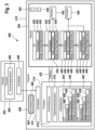
- the 1 shows a system 100 from a reloading machine 102 and a chip card 104.
- the reloading machine 102 includes a communication interface 106, a control module 108 and a storage module for temporary user data 110.
- the reloading machine 102 shown also includes an authentication token 112, a reloading token 114 , a further communication interface 116 and an energy source 118.
- the authentication token 112 and the second communication interface 116 represent optional features of the reloading machine 102.
- the energy source 118 can be, for example, a battery or a power-generating unit such as a fuel cell or a solar cell.
- a closed energy source 118 could have the advantage that the automatic reloader 102 can be designed to be completely self-sufficient on the one hand and portable on the other.
- the energy source 118 can also be a power pack or some other type of connection to an external energy supply.
- a combination of External and internal power supply possible, which would improve the reliability of the reloading machine 102.
- the storage module for temporary user data 110 can be both a volatile and a non-volatile memory. If, for example, a connection to a power grid is provided as the energy source 118 of the automatic reloading device 102, it can be useful to design the memory module for temporary user data 110 as a non-volatile memory. If the power supply to the automatic reloader 102 were interrupted during a reloading process after the first data set had been transmitted to the automatic reloader, the first data record would be deleted from a volatile memory, with the result that the user data contained in the first data record would be lost. This would be avoided by a non-volatile memory.
- the storage module for temporary user data 110 can also be in the form of a volatile memory. This would have the advantage, in particular, that after the automatic reloading machine was switched off and the software of a chip card 104 was successfully updated, the user data 124, 126 of the chip card 104 stored in the automatic reloading machine 102 would be automatically deleted. This would prevent the user data from being misused by subsequent reading out of the automatic reloading device 102 .
- the chip card 104 contains a chip card operating system 120 and a logical data structure 122 and user data 124. Furthermore, user data 126 is also stored in the logical data structure 122. In this case, the user data 126, which is stored in the logical data structure 122, can be linked to the user data 124 stored outside of the logical data structure 122 by references. Control data 128 and 130 are also stored in the logical data structure 122, it being possible for the control data 128 to be assigned to an application, while the control data 130 is assigned to a set of useful data.
- communication between the automatic reloading machine 102 and the chip card 104 is possible through the communication interface 106 of the automatic reloading machine 102 .
- the chip card 104 can be addressed through the communication interface 106, as a result of which a reloading process can be initiated.
- the communication interface 106 can be designed in accordance with ISO 14443, for example.
- the further communication interface 116 of the automatic reloading device 102 can be designed for the administration of the automatic reloading device 102, for example.
- the communication interface 116 can be an Ethernet connection.
- the authentication token 112 and also the reloading token 114 can be in the form of both a software token and a hardware token, for example in the form of a chip card for insertion into the reloading machine 102 .
- the reload token 114 can be supplied by a manufacturer of the chip card 104 to be renewed and then contains the software to be reloaded.
- the reloading token 114 it is also possible for the reloading token 114 to be permanently installed in the reloading machine 102 so that manufacturer-specific reloading software would have to be transferred to the reloading machine 102 via the communication interface 116 .
- the reloading token 114 can also be designed as a storage area within the automatic reloading device 102 .
- the communication interface 106 via which communication between the automatic reloading machine 102 and the chip card 104 is to be ensured, can also have a mechanical retraction for partially or completely receiving the chip card 104 in the automatic reloading machine 102.
- the retraction can be such that it protects the chip card 104 from being removed from the automatic reloading machine 102 by a chip card user at least for the duration of the reloading process. This ensures uninterrupted communication and power supply during the reloading process.
- the reloading machine 102 is designed to replace at least parts of the logical data structure 122 stored in the chip card 104 and the operating system 120 stored in the chip card 104 with a renewed operating system or a newer logical data structure in the course of a reloading process to replace.
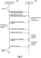
- the reloading process is a multi-step process that is preceded by an initialization.
- the reloading software is either loaded onto the reloading machine 102 as a software token via the communication interface 116 or is introduced into the reloading machine 102 as a hardware token 114 .
- the reloading software can support exactly one chip card type and version, or be designed as a package to support several chip card types and versions.
- the reloading machine 102 is activated.
- activation can take place by actuating a power switch, or the automatic reloading device 102 can be designed in such a way that it is woken up from an idle state when a chip card 104 is inserted into a corresponding mechanical feeder.
- An operator authentication can then be provided, for example by means of a password query, which, if successful, initiates the reloading process.
- the reloading machine 102 must have a suitable input option, such as a keyboard, and the authentication token 112 .
- a communication channel between the reloading machine 102 and the chip card 104 is set up. This can be done, for example, by inserting the chip card 104 into the slot of a card reader or by establishing a wireless connection.
- the reloading machine 102 reads generally available card data from the chip card 104, for example to determine the support for the chip card type and version. For reasons of data protection, it can be provided that the exact version number of the operating system 120 or the logical data structure 122 of the chip card 104 may not initially be read out.
- the reloading machine 102 and the chip card 104 are then mutually authenticated, so that a secure channel can be set up between the reloading machine 102 and the chip card 104 .
- corresponding authentication data can be stored in the automatic reloading machine 102, for example in the authentication token 112, which are used in the course of the mutual authentication.
- a necessary authorization of the automatic reloading device 102 for reloading data into the smart card 104 is obtained by the authentication of the automatic reloading device 102 in relation to the chip card 104 . It can be provided that the authentication of the chip card 104 to the reloading machine 102 proves the correct supporting chip card type.
- an authentication value can be generated in the chip card 104, in which chip-card-specific attributes flow.
- the exact version number of the operating system of the logical data structure and the user data version of the chip card 104 can also be read.
- the control module 108 of the automatic reloading device 102 determines the reloading software that matches the chip card type and version, as well as the reloading mode, for example patch, update or upgrade.
- the chip card 104 In a subsequent step, the chip card 104 generates or activates an already existing chip-specific key for encrypting all or parts of the user data 124, 126 and/or all or parts of the logical data structure 122.
- separate encryption keys for the user data 124, 126 and the logical data structure 122 can be generated.
- a key for integrity protection can be generated for each encryption key. This key can be used, for example, to sign the first data record that results from the encryption of user data and the logical data structure. All or parts of the user data 124, 126 and/or all or parts of the logical data structure 122 are then transmitted in encrypted form to the reloading machine 102 via the secure channel.
- the automatic reloader 102 then stores the received data (first data set) in the memory 110.
- the user data 124, 126, the logical data structure 122 and the operating system 120 in the chip card 104 are deleted, according to the previously determined mode of reloading.
- the data can be deleted from the chip card 104 by the chip card 104 itself or by the reloading machine 102 .
- the new entire or parts of the operating system 120 and/or all or parts of the logical data structure 122 are then transmitted from the reload token 114 of the reload machine 102 to the chip card 104 via the secure channel according to the previously determined reload mode.
- the chip card 104 verifies the data obtained in this way and installs the new operating system 120 and/or logical data structure 122 in the chip card 104.
- the data can be verified, for example, by verifying a signature of the data.
- the signature is generated, for example, by a manufacturer of the reloading software and the verification key is stored in the operating system or in a boot loader of the chip card 104 .
- the encrypted data in the form of the first data set is read from the memory 110 of the reloading machine 102 and transmitted to the chip card 104 via the secure channel.
- the chip card 104 then decrypts the data contained in the first data set and installs all or parts of the user data 124, 126 and/or all or parts of the logical data structure 122. According to one embodiment, it can be provided that the chip card 104 first uses a signature to check whether the first data set has been corrupted or not.
- connection and the secure channel between automatic reloading machine 102 and chip card 104 are then terminated and the first data record is deleted from memory 110 of automatic reloading machine 102 .
- the reloading machine 102 triggers the update of the control data 128 in the course of playing back the first data set on the chip card 104, 130.
- a flag can be transmitted for this purpose, which causes the chip card 104 to, when the user data 124, 126 is restored from the first data set, the control data 128, 130 according to the reloaded adapt functionalities.
- the connection between the reloading machine 102 and the chip card 104 must be maintained until the update of the control data 128, 130 has been completed.
- the 3 shows a chip card system 400 with a terminal 402.
- the terminal 402 can be, for example, a reading device for an official document, in particular for an electronic identity card, an electronic residence permit or an electronic passport.
- the terminal 402 has a processor 404 for executing an application program 406, which is interoperable with a document 410, and an interface 408 for establishing a communication connection with a corresponding interface 412 of the document 410.
- the interfaces 408 and 412 can be embodied as contact-based or contactless interfaces, in particular in accordance with ISO14443, for example as NFC interfaces.
- the document 410 preferably does not have its own energy supply, but is supplied with electrical energy by coupling electromagnetic energy from the interface 408 into the interface 412, for which purpose the interface 412 has an antenna in the case of the wireless embodiment.
- the document 410 has a processor 414 for executing a program module 416 for the authentication of the terminal 402 or the mutual authentication of the terminal 402 and the document 410.
- the program module 416 implement, for example, those steps of a challenge-response protocol that relate to the document 410, wherein the application program 406 can then implement those steps of the challenge-response protocol that relate to the terminal 402.
- Another possibility is authentication by means of a secret identifier, for example a so-called PIN, which a user enters into the terminal and which is checked by the program module 416, for example according to the PACE protocol, as specified by the Federal Office for Information Security (BSI) has been specified.
- a secret identifier for example a so-called PIN
- PACE Federal Office for Information Security
- the processor 414 is also used to run a chip card operating system 418 and has a volatile main memory 420.
- the processor 416 is connected to the interface 412 of the document 410 and via an internal data bus 422 to a non-volatile protected electronic memory 424.
- FIG. 12 shows an example of a DF 426 of the file tree, which contains control data 428 including a pointer 430 to a successor node, i.e. the EF 432.
- the EF 432 also includes control data 434, including a pointer 438 to its successor node in the file tree, namely an EF 440, and a pointer 436 to payload data 442 associated with the EF 432 but not in the EF 432 or any other file in the file tree are saved.
- the EF 440 has a structure analogous thereto, which contains control data 444, including a pointer 446, to the user data 450 assigned to the EF 440 and a pointer 448 to one in the 3 child nodes, not shown, of EF 440 in the file tree.
- the procedure can be as follows, for example, as in FIG 4 shown:
- the terminal 402 is first authenticated with respect to the document 410.
- an authorization check can also be carried out done, namely whether the terminal 402 has the necessary rights to change control data. This can be done, for example, in such a way that the terminal 402 transmits an authorization certificate to the document 410, the authorization certificate specifying the rights of the terminal 402 to change the control data.
- the document 410 receives changed control data from the terminal 402, for example by the application program 406 sending a command APDU 458 from the interface 408 to the interface 412, which contains the changed control data and also a specification of the file of the chip card file system, whose Control data to be changed. Without restricting the generality, it is assumed below, for example, that this is the EF 440 or its control data 444.
- step 504 the chip card operating system 418 sets a flag F 452 in the memory 424. Furthermore, a log file P can also be created in the memory 424 in order to log the subsequent steps for changing the control data.
- step 506 the chip card operating system 418 accesses the memory 424 via the internal data bus 422 and reads the EF 440.
- the chip card operating system 418 then stores a copy 456 of the EF 440 in the main memory 420.
- the control data 444 of the copy 456 is then updated.
- the command APDU 458 contains the changed control data 444' and an identifier (ID) 460 of the file whose control data is to be changed, here the EF 440.
- ID identifier
- the smart card operating system 418 writes the changed control data 444' of the APDU 458 to the copy 456 of the EF 440, which is temporarily stored in the main memory 420, thereby replacing the previous version of the control data 444.
- the pointers 446 and 448 remain unchanged (step 508). .
- step 510 the modified copy EF ⁇ 456 of the EF 440 is then stored in a memory area of the memory 424, which differs from the memory area in which the EF 440 is stored is different. This is particularly necessary when the control data 444' has a larger volume than the control data 444, so that the modified copy 456 is larger than the previous version, i.e. the EF 440.
- step 514 the modified copy 456 that is in the Memory 424 is stored activated and the original, i.e. the EF 440, deactivated or deleted.
- the EF 432 is now also updated by temporarily storing a copy 462 of the EF 432 in the working memory 420 in step 514 and in step 516 the Pointer 438 to the successor node in copy 462 is updated by replacing the previous pointer to EF 440 with a pointer to the memory area in memory 424 of copy EF ⁇ 456.
- the remaining control data 434 including the pointer to the user data 436 can remain unchanged.
- step 518 the modified copy 462 of the EF 432 is stored in the memory 424 , which can be done in such a way that the copy 462 overwrites the EF 432 .
- This is possible because only the pointer 438 has been updated, so the file size of the EF 432 and the modified copy 462 are the same.
- the flag 452 is reset in step 520 and the log file 454 is deleted.
- the chip card operating system 418 can then also be updated. This can be necessary if the original version of the chip card operating system 418 does not contain a function to check a cryptographic access condition for the user data 450 specified by the changed control data 444′.
- BAC Basic Access Control
- EAC Extended Access Control
- the document 410 receives update data for the chip card operating system 418 from the terminal 402, which contains program codes for the implementation of the additional function. Based on this update data, the chip card operating system 418 is then updated in step 524.
- FIG. 12 is a schematic representation of a first possible defragmentation method. It is assumed here that the non-volatile electronic memory 110 of the chip card 104 has a size or a storage volume which is indicated by the arrow 202 . As in Fig. 5 a) shown, the memory comprises four occupied memory areas 204, 206, 208 and 210. Between these occupied memory areas there are three unoccupied memory areas 212, 214 and 216.
- a first unoccupied memory area is determined, in this case memory area 212. Then the first occupied memory area 206 following the unoccupied memory area 212 is determined. This is then moved to the start position of the unoccupied memory area 212. The result of this step is in Fig. 5 b) shown.
- the occupied memory area 208 is converted to the occupied memory area 206 moved to the following unoccupied memory area. The result of this shift is in Fig. 5 c) shown.
- the 6 Figure 12 is a schematic representation of another possible defragmentation method. Analogous to the in figure 5 In the initial situation shown, four occupied memory areas 302, 304, 306 and 308 are also present in a memory of a defined size, indicated by the arrow 302. As also in Fig. 6 a) shown, the memory is initially fragmented.
Landscapes
- Engineering & Computer Science (AREA)
- Theoretical Computer Science (AREA)
- Software Systems (AREA)
- General Engineering & Computer Science (AREA)
- Physics & Mathematics (AREA)
- Computer Hardware Design (AREA)
- General Physics & Mathematics (AREA)
- Computer Security & Cryptography (AREA)
- Mathematical Physics (AREA)
- Storage Device Security (AREA)
Claims (15)
- Procédé pour recharger un logiciel fourni par un automate de rechargement (102) sur une carte à puce (104, 410) par l'automate de rechargement (102), dans lequel la carte à puce (104, 410) présente un processeur (414), une interface de communication (412) et une mémoire électronique (424) non volatile avec une structure de données (122) logique y étant enregistrée, ainsi que des données d'utilisation (124, 126, 442, 450) et des données de commande (128, 130), dans lequel l'automate de rechargement (102) comprend un jeton d'authentification (112), où le jeton d'authentification (112) contient des données permettant une authentification d'un utilisateur de l'automate de rechargement (102), où le jeton d'authentification (112) est conçu sous forme d'un support de données physique échangeable, où uniquement l'utilisateur en question, dont le jeton d'authentification est relié effectivement avec l'automate de rechargement, peut utiliser l'automate de rechargement,
où le procédé comprend :a) l'établissement d'une connexion de communication entre l'automate de rechargement (102) et la carte à puce (104) par le biais de l'interface de communication (412, 106), où l'établissement de la connexion de communication contient une authentification réciproque de l'automate de rechargement (102) et de la carte à puce (104, 410), c'est la raison pour laquelle des données d'authentification sont stockées dans le jeton d'authentification (112), lesquelles sont employées dans le cadre de l'authentification réciproque, où un canal de communication sécurisé entre l'automate de rechargement (102) et la carte à puce (104) est établi par l'authentification,b) la création d'un premier ensemble de données par le processeur (414) par le chiffrement d'au moins une partie des données d'utilisation (124, 126, 442, 450) stockées dans la mémoire électronique (424) non volatile et/ou d'au moins une partie des données de commande (128, 130) stockées dans la mémoire électronique (424) non volatile, et/ou de la structure de données (122) logique,c) la transmission du premier ensemble de données à l'automate de rechargement (102) par le biais de la connexion de communication, où le premier ensemble de données est transmis exclusivement par le biais du canal de communication sécurisé,d) le stockage du premier ensemble de données dans l'automate de rechargement (102),e) le rechargement du logiciel sur la carte à puce (104, 410) par la transmission du logiciel à recharger sur la carte à puce (104, 410) par le biais de la connexion de communication et le stockage du logiciel transmis dans la mémoire électronique (424) non volatile, où l'automate de rechargement (102) n'obtient l'accès aux données contenues sur la carte à puce (104, 410) qu'après une authentification réussie par rapport à la carte à puce (104, 410),f) la transmission du premier ensemble de données à la carte à puce (104, 410) par le biais de la connexion de communication,g) la restauration des données d'utilisation (124, 126, 442, 450), et/ou des données de commande (128, 130), et/ou de la structure de données (122) logique de la carte à puce (104, 410) par le déchiffrement du premier ensemble de données par le processeur (414) et le stockage des données d'utilisation (124, 126, 442, 450) contenues dans le premier ensemble de données, et/ou des données de commande (128, 130), et/ou de la structure de données (122) logique, dans la mémoire électronique (424) non volatile. - Procédé selon la revendication 1, dans lequel la carte à puce (104, 410) présente un système de fonctionnement de carte à puce (120, 418) avec un système de données de carte à puce (122) hiérarchiques et des applications y étant enregistrées, dans lequel le logiciel à recharger comprend un système de fonctionnement de carte à puce (120, 418) et/ou des applications, lesquels doivent remplacer un système de fonctionnement de carte à puce (120, 418) installé sur la carte à puce (104, 410) et/ou une première partie des applications installées sur la carte à puce (104, 410), où le rechargement du logiciel sur la carte à puce (104, 410) comprend l'effacement des données d'utilisation (124, 126, 442, 450), et/ou des données de commande (128, 130), et/ou de la structure de données (122) logique, ainsi que les autres étapes suivantes :• entre l'étape d) et l'étape e), l'effacement du système de fonctionnement de carte à puce (120, 418), et/ou de la première partie des applications,• entre l'étape e) et l'étape f), l'installation du logiciel rechargé sur la carte à puce (104, 410) par le processeur (414), oudans lequel la carte à puce (104, 410) présente un système de fonctionnement de carte à puce (120, 418) avec un système de données de carte à puce (122) hiérarchiques et des applications y étant enregistrées, dans lequel le logiciel à recharger comprend un système de fonctionnement de carte à puce (120, 418) et/ou des applications, lesquels doivent remplacer un système de fonctionnement de carte à puce (120, 418) installé sur la carte à puce (104, 410), et/ou une première partie des applications installées sur la carte à puce (104, 410), où le rechargement du logiciel sur la carte à puce (104, 410) comprend :• l'effacement des données d'utilisation (124, 126, 442, 450) transmises dans le premier ensemble de données à l'automate de rechargement (102), et/ou des données de commande (128, 130), et/ou de la structure de données (122) logique, de la mémoire électronique (424) non volatile après l'étape c) ou l'étape d),• dans l'étape e), l'enregistrement du logiciel transmis dans la zone de mémoire de la première mémoire électronique (424) non volatile devenue libre par l'effacement des données d'utilisation (124, 126, 442, 450) transmises dans le premier ensemble de données à l'automate de rechargement (102), et/ou des données de commande (128, 130), et/ou de la structure de données (122) logique,• l'installation du logiciel rechargé sur la carte à puce (104, 410) par le processeur (414),• l'exécution d'une vérification de fonctionnement du logiciel rechargé installé, dans lequel, lors d'un constat d'une fonctionnalité correcte du logiciel rechargé installé, le procédé comprend l'effacement du premier système de fonctionnement de carte à puce (120, 418), et/ou de la première partie des applications, et dans lequel, lors d'un constat d'une fonctionnalité défaillante du logiciel installé, le procédé comprend l'effacement du logiciel rechargé nouvellement installé.
- Procédé selon l'une des revendications précédentes, dans lequel l'automate de rechargement (102) détermine au moins un identificateur de la carte à puce (104, 410) après l'établissement du canal de communication sécurisé avec la carte à puce (104, 410), dans lequel l'automate de rechargement (102) détermine le logiciel à recharger sur la carte à puce (104, 410) à l'aide de l'au moins un identificateur.
- Procédé selon l'une des revendications précédentes, doté en outre d'un jeton de rechargement (114), dans lequel le logiciel à recharger est contenu sur le jeton de rechargement (114), dans lequel le jeton de rechargement (114) est relié avec l'automate de rechargement (102) au début du procédé, dans lequel la liaison entre l'automate de rechargement (102) et le jeton de rechargement (114) est conçue pour une transmission de données entre l'automate de rechargement (102) et le jeton de rechargement (114), dans lequel l'automate de rechargement (102) est conçu pour transmettre le logiciel à recharger à partir du jeton de rechargement (114) dans la première mémoire électronique (424) non volatile de la carte à puce (104, 410) par le biais de la connexion de communication.
- Procédé selon l'une des revendications précédentes, dans lequel la carte à puce (104, 410) présente une zone de mémoire protégée non volatile protégée contre l'écriture, dans lequel la zone de mémoire protégée contre l'écriture contient au moins la fonction de déchiffrement du premier ensemble de données, ainsi que le matériel en clés nécessaire à cet effet.
- Procédé selon la revendication 5, dans lequel le premier ensemble de données est généré par un chiffrement symétrique avec une clé individuelle de la carte à puce, dans lequel la clé individuelle de la carte à puce est enregistrée dans la zone de mémoire sécurisée, ou bien, dans lequel la clé individuelle de la carte à puce est dérivée d'attributs spécifiques à la carte à puce, dans lequel la clé individuelle de la carte à puce n'est générée après l'étape de procédé a).
- Procédé selon l'une des revendications précédentes, dans lequel le premier ensemble de données est signé avec une clé individuelle de la carte à puce par la carte à puce (104, 410), dans lequel la signature du premier ensemble de données est vérifiée après la réception du premier ensemble de données par l'automate de rechargement (102), dans lequel le premier ensemble de données est installé uniquement pour une vérification réussie de la signature du premier ensemble de données.
- Procédé selon l'une des revendications précédentes 2 à 7, où le procédé comprend en outre une modification de données de commande (444, 128, 130) de la carte à puce (104, 410), dans lequel la carte à puce (104, 410) présente une mémoire de travail (420) volatile, dans lequel le système de données de carte à puce contient des fichiers de répertoire (DFs) et des fichiers de données (EFs), dans lequel une arborescence de fichiers constituée d'au moins un fichier de répertoire (426) et de plusieurs fichiers de données (432, 440, ...) est stockée dans la mémoire électronique (424) non volatile, dans lequel, dans au moins un des fichiers, sont stockées des données de commande (444, 128, 130) pour les données d'utilisation (450), les données d'utilisation sont stockées dans une zone de mémoire de la mémoire électronique non volatile et un indicateur (446) est stocké sur cette zone de mémoire dans l'au moins un fichier de données (440), dans lequel la carte à puce est activée pour le fonctionnement actif, dans lequel, pour la modification des données de commande par le système de fonctionnement de carte à puce, une copie (456) d'au moins une arborescence partielle de l'arborescence de fichiers contenant le fichier (440) est stockée dans la carte à puce de manière temporaire dans la mémoire de travail (420), des données de commande (444, 128, 130) modifiées sont stockées dans l'au moins un fichier de l'arborescence partielle copiée, et la copie modifiée de l'arborescence partielle est stockée de manière permanente dans la première mémoire électronique et est activée, et l'arborescence partielle d'origine est effacée ou désactivée, ou les modifications des données de commande sont directement exécutées dans la première mémoire non volatile.
- Procédé selon l'une des revendications précédentes, dans lequel les données d'utilisation (124, 126, 442, 450) contiennent des codes de programme relocalisables, dans lequel, après la restauration des données d'utilisation (124, 126, 442, 450), la mémoire électronique (424) non volatile comprend des zones de mémoires non occupées (212, 214,...) et des zones de mémoire occupées (204, 206, ...) avec des codes de programmes relocalisables, où le procédé comprend en outre la défragmentation de la mémoire électronique (424) non volatile, dans lequel la défragmentation comprend un déplacement du code de programme relocalisable stocké dans les zones de mémoire occupées de sorte que plusieurs parmi les zones de mémoire non occupées forment une zone de mémoire non occupée assemblée.
- Procédé selon la revendication 9, dans lequel la défragmentation comprend le classement, l'un derrière l'autre, des codes de programme relocalisables stockés dans les zones de mémoire occupées (204, 206,...) par un déplacement physique du code de programme relocalisable, et/ou
dans lequel le classement logique des zones de mémoire de la mémoire électronique (424) non volatile est fixé par un tableau d'association, dans lequel la défragmentation comprend le classement d'une partie des zones de mémoire occupées (204, 206, ...) par une manipulation du tableau d'association. - Procédé selon l'une des revendications précédentes 9 et 10, dans lequel la défragmentation comprend :a) la détermination d'une première position d'une première zone de mémoire non occupée (212),b) la détermination d'une deuxième position d'une deuxième zone de mémoire occupée (206), dans lequel la deuxième zone de mémoire occupée (206) suit directement de manière logique la première zone de mémoire libre (212) dans la mémoire,c) le déplacement du code de programme relocalisable stocké dans la deuxième zone de mémoire occupée (206) à la première position,dans lequel les étapes précédemment décrites sont répétées aussi longtemps qu'il n'y a pas de zone de mémoire occupée postérieure à la première zone de mémoire non occupée (212), oudans lequel la défragmentation comprend :a) la détermination des positions et des tailles respectives des zones de mémoire occupées (204, 206, ...),b) la détermination des positions et des tailles respectives des zones de mémoire non occupées (212,214, ...),c) le déplacement du code de programme relocalisable stocké dans une zone de mémoire occupée à des positions de zones de mémoire non occupées de taille identique ou supérieure.
- Procédé selon l'une des revendications 10 ou 11, dans lequel la défragmentation comprend en outre la définition d'une valeur limite pour la taille d'une zone de mémoire occupée (204, 206, ...), dans lequel le déplacement d'un code de programme relocalisable stocké dans des zones de mémoire occupées (204, 206, ...) a lieu avec une taille qui est supérieure à la valeur limite par une manipulation du tableau d'association, et dans lequel le déplacement d'un code de programme relocalisable stocké dans des zones de mémoire occupées (204, 206, ...) a lieu avec une taille qui est inférieure à la valeur limite par un déplacement physique du code de programme relocalisable des zones de mémoire occupées (204, 206,...).
- Automate de rechargement (102), l'automate de rechargement (102) étant conçu pour recharger un logiciel fourni par l'automate de rechargement (102) sur une carte à puce (104, 410), l'automate de rechargement (102) comprenant un jeton d'authentification (112), dans lequel le jeton d'authentification (112) contient des données pour une authentification d'un utilisateur de l'automate de rechargement (102), dans lequel le jeton d'authentification (112) est conçu sous forme d'un support de données physique échangeable, où uniquement l'utilisateur en question, dont le jeton d'authentification est relié effectivement avec l'automate de rechargement, peut utiliser l'automate de rechargement, où le rechargement par l'automate de rechargement ((102) comprend :a) l'établissement d'une connexion de communication avec la carte à puce (104, 410), où l'établissement de la connexion de communication contient une authentification réciproque de l'automate de rechargement (102) et de la carte à puce (104, 410), c'est la raison pour laquelle des données d'authentification sont stockées dans le jeton d'authentification (112), lesquelles sont employées dans le cadre de l'authentification réciproque, où un canal de communication sécurisé entre l'automate de rechargement (102) et la carte à puce (104) est établi par l'authentification,b) la réception d'un premier ensemble de données à partir de la carte à puce (104, 410) par le biais de la connexion de communication, où le premier ensemble de données est exclusivement transmis par le biais du canal de communication sécurisé,c) le stockage du premier ensemble de données,d) le rechargement du logiciel sur la carte à puce (104, 410) par l'accès à la carte à puce (104, 410), où l'automate de rechargement (102) n'obtient l'accès aux données contenues sur la carte à puce (104, 410) qu'après une authentification réussie par rapport à la carte à puce (104, 410) par le biais de la connexion de communication,e) la transmission du premier ensemble de données à la carte à puce (104, 410) par le biais de la connexion de communication.
- Automate de rechargement (102) selon la revendication 13, où l'automate de rechargement (102) présente une entrée mécanique, où l'entrée mécanique est conçue pour la réception de la carte à puce (104, 410), où l'entrée est en outre conçue pour protéger la carte à puce (104, 410) contre un retrait de l'automate de rechargement (102) lors du processus de rechargement aussi longtemps que le procédé de rechargement n'est pas terminé, et/ouoù l'automate de rechargement (102) comprend une source d'énergie (118), où, dans le cas de la source d'énergie (118), il s'agit d'une source d'énergie interne enfermée et/ou d'une source d'énergie externe, et/ouoù l'automate de rechargement (102) comprend un jeton de rechargement (114), où le jeton de rechargement (114) contient le logiciel à recharger sur la carte à puce (104), où le jeton de rechargement (114) est conçu sous forme de support de données physique échangeable.
- Système comprenant un automate de rechargement (102) selon l'une des revendications 13 à 14 et une carte à puce (104, 410) avec au moins une mémoire électronique (424) non volatile avec une structure de données (122) logique y étant enregistrée, ainsi que des données d'utilisation (124, 126, 442, 450) et des données de commande (128, 130), un processeur (414) et une interface de communication (412), dans lequel la carte à puce (104, 410) est conçue pour exécuter le procédé suivant :a) l'établissement d'une connexion de communication avec l'automate de rechargement (102) par le biais de l'interface de communication (412), où l'établissement de la connexion de communication contient une authentification réciproque de l'automate de rechargement (102) et de la carte à puce (104, 410), c'est la raison pour laquelle des données d'authentification sont stockées dans le jeton d'authentification (112), lesquelles sont employées dans le cadre de l'authentification réciproque, où un canal de communication sécurisé entre l'automate de rechargement (102) et la carte à puce (104) est établi par l'authentification,b) la création d'un premier ensemble de données par le processeur (414) par le chiffrement d'au moins une partie des données d'utilisation (124, 126, 442, 450) stockées dans la mémoire électronique (424) non volatile et/ou d'au moins une partie des données de commande (128, 130) stockées dans la mémoire électronique (424) non volatile, et/ou de la structure de données (122) logique,c) la transmission du premier ensemble de données à l'automate de rechargement (102) par le biais de la connexion de communication pour le stockage du premier ensemble de données dans l'automate de rechargement (102), où le premier ensemble de données est transmis exclusivement par le biais du canal de communication sécurisé,d) le rechargement du logiciel sur la carte à puce (104, 410) dans la mémoire électronique (424) non volatile par le biais de la connexion de communication, où l'automate de rechargement (102) n'obtient l'accès aux données contenues sur la carte à puce (104, 410) qu'après une authentification réussie par rapport à la carte à puce (104, 410),e) la réception du premier ensemble de données à partir de l'automate de rechargement (102) par le biais de la connexion de communication,f) la restauration des données d'utilisation, et/ou des données de commande (128, 130), et/ou de la structure de données (122) logique dans la carte à puce (104, 410) par le déchiffrement du premier ensemble de données par le processeur (414) et le stockage des données d'utilisation (124, 126, 442, 450) contenues dans le premier ensemble de données, et/ou des données de commande (128, 130), et/ou de la structure de données (122) logique, dans la mémoire électronique (424) non volatile.
Applications Claiming Priority (3)
| Application Number | Priority Date | Filing Date | Title |
|---|---|---|---|
| DE102014224278.9A DE102014224278A1 (de) | 2014-11-27 | 2014-11-27 | Verfahren zum Nachladen von Software auf eine Chipkarte durch einen Nachladeautomaten |
| EP15802062.8A EP3224756B1 (fr) | 2014-11-27 | 2015-11-26 | Procédé pour recharger un logiciel sur une carte à puce par l'intermédiaire d'un dispositif automatique de rechargement |
| PCT/EP2015/077826 WO2016083532A2 (fr) | 2014-11-27 | 2015-11-26 | Procédé pour recharger un logiciel sur une carte à puce par l'intermédiaire d'un dispositif automatique de rechargement |
Related Parent Applications (2)
| Application Number | Title | Priority Date | Filing Date |
|---|---|---|---|
| EP15802062.8A Division EP3224756B1 (fr) | 2014-11-27 | 2015-11-26 | Procédé pour recharger un logiciel sur une carte à puce par l'intermédiaire d'un dispositif automatique de rechargement |
| EP15802062.8A Division-Into EP3224756B1 (fr) | 2014-11-27 | 2015-11-26 | Procédé pour recharger un logiciel sur une carte à puce par l'intermédiaire d'un dispositif automatique de rechargement |
Publications (2)
| Publication Number | Publication Date |
|---|---|
| EP3754530A1 EP3754530A1 (fr) | 2020-12-23 |
| EP3754530B1 true EP3754530B1 (fr) | 2023-03-22 |
Family
ID=54754625
Family Applications (3)
| Application Number | Title | Priority Date | Filing Date |
|---|---|---|---|
| EP20182244.2A Active EP3754529B1 (fr) | 2014-11-27 | 2015-11-26 | Procédé pour recharger un logiciel sur une carte à puce par l'intermédiaire d'un dispositif automatique de rechargement |
| EP20182246.7A Active EP3754530B1 (fr) | 2014-11-27 | 2015-11-26 | Procédé pour recharger un logiciel sur une carte à puce par l'intermédiaire d'un dispositif automatique de rechargement |
| EP15802062.8A Active EP3224756B1 (fr) | 2014-11-27 | 2015-11-26 | Procédé pour recharger un logiciel sur une carte à puce par l'intermédiaire d'un dispositif automatique de rechargement |
Family Applications Before (1)
| Application Number | Title | Priority Date | Filing Date |
|---|---|---|---|
| EP20182244.2A Active EP3754529B1 (fr) | 2014-11-27 | 2015-11-26 | Procédé pour recharger un logiciel sur une carte à puce par l'intermédiaire d'un dispositif automatique de rechargement |
Family Applications After (1)
| Application Number | Title | Priority Date | Filing Date |
|---|---|---|---|
| EP15802062.8A Active EP3224756B1 (fr) | 2014-11-27 | 2015-11-26 | Procédé pour recharger un logiciel sur une carte à puce par l'intermédiaire d'un dispositif automatique de rechargement |
Country Status (3)
| Country | Link |
|---|---|
| EP (3) | EP3754529B1 (fr) |
| DE (1) | DE102014224278A1 (fr) |
| WO (1) | WO2016083532A2 (fr) |
Families Citing this family (3)
| Publication number | Priority date | Publication date | Assignee | Title |
|---|---|---|---|---|
| CN109189407A (zh) * | 2018-08-01 | 2019-01-11 | 广州华望汽车电子有限公司 | 一种对多芯片烧录的统计方法、系统、装置和存储介质 |
| CN113360955B (zh) * | 2021-06-16 | 2024-06-04 | 深圳市雪球科技有限公司 | 一种Applet管理方法、装置和服务器 |
| CN116578352B (zh) * | 2023-07-11 | 2023-09-22 | 沐曦集成电路(上海)有限公司 | 芯片初始化系统 |
Family Cites Families (8)
| Publication number | Priority date | Publication date | Assignee | Title |
|---|---|---|---|---|
| JP2006119901A (ja) * | 2004-10-21 | 2006-05-11 | Toshiba Corp | 携帯可能電子装置および携帯可能電子装置のアプリケーション更新方法 |
| US7721059B2 (en) * | 2006-07-06 | 2010-05-18 | Nokia Corporation | Performance optimization in solid-state media |
| US8347055B2 (en) * | 2009-06-30 | 2013-01-01 | Incard S.A. | Method to defrag a memory of an IC card |
| EP2453352A1 (fr) * | 2010-11-08 | 2012-05-16 | Gemalto SA | Procédé de mise à jour de logiciel pour dispositif intégré |
| FR2993682B1 (fr) * | 2012-07-20 | 2014-08-22 | Oberthur Technologies | Mise a jour d'un systeme d'exploitation pour element securise |
| US8935689B2 (en) * | 2012-08-13 | 2015-01-13 | International Business Machines Corporation | Concurrent embedded application update and migration |
| US20140189211A1 (en) * | 2012-12-31 | 2014-07-03 | Sandisk Enterprise Ip Llc | Remapping Blocks in a Storage Device |
| US20140229657A1 (en) * | 2013-02-08 | 2014-08-14 | Microsoft Corporation | Readdressing memory for non-volatile storage devices |
-
2014
- 2014-11-27 DE DE102014224278.9A patent/DE102014224278A1/de not_active Withdrawn
-
2015
- 2015-11-26 EP EP20182244.2A patent/EP3754529B1/fr active Active
- 2015-11-26 WO PCT/EP2015/077826 patent/WO2016083532A2/fr not_active Ceased
- 2015-11-26 EP EP20182246.7A patent/EP3754530B1/fr active Active
- 2015-11-26 EP EP15802062.8A patent/EP3224756B1/fr active Active
Also Published As
| Publication number | Publication date |
|---|---|
| WO2016083532A2 (fr) | 2016-06-02 |
| WO2016083532A3 (fr) | 2016-07-21 |
| DE102014224278A1 (de) | 2016-06-02 |
| EP3224756A2 (fr) | 2017-10-04 |
| EP3754530A1 (fr) | 2020-12-23 |
| EP3754529B1 (fr) | 2023-06-14 |
| EP3754529A1 (fr) | 2020-12-23 |
| EP3224756B1 (fr) | 2021-02-17 |
Similar Documents
| Publication | Publication Date | Title |
|---|---|---|
| DE102009013384B4 (de) | System und Verfahren zur Bereitstellung einer sicheren Anwendungsfragmentierungsumgebung | |
| DE102020119389A1 (de) | Vorrichtung und Verfahren zum sicheren Verwalten von Schlüsseln | |
| DE102014220616A1 (de) | Verfahren zum Laden von ausführbaren Programminstruktionen in eine Chipkarte im Wirkbetrieb | |
| DE112023002184T5 (de) | Sram physically unclonable function (puf) speicher zum erzeugen von schlüsseln basierend auf dem besitzer der vorrichtung | |
| EP3754529B1 (fr) | Procédé pour recharger un logiciel sur une carte à puce par l'intermédiaire d'un dispositif automatique de rechargement | |
| EP3286872B1 (fr) | Obtention d'une clé cryptographique spécifique d'un appareil à partir d'une clé intersystème pour un appareil | |
| EP3308278B1 (fr) | Procédé de mise à jour de données de personnalisation | |
| DE112022000914T5 (de) | Steuervorrichtung und steuersystem | |
| EP3329415B1 (fr) | Carte a puce avec une application principale et une application persistante permettant de mettre a jour l'application principale sans modifier les donnees d'utilisateur stockees dans l'application persistante | |
| EP1762956A2 (fr) | Ordinateur avec au moins un connecteur pour un support d'information amovible et procédé de démarrer et d'utilisation d'un ordinateur avec un support d'information amovible | |
| EP3887989A1 (fr) | Élement sûr en tant que module de plateforme de confiance pouvant être mis à jour | |
| DE102014224186B4 (de) | Verfahren zum Nachladen einer Anwendung auf ein Dokument | |
| EP3215957B1 (fr) | Carte à puce, système de carte à puce et procédé d'accès à une carte à puce | |
| EP3175383B1 (fr) | Procédé pour modifier les données de contrôle d'une carte à puce et système de carte à puce | |
| WO2010040423A1 (fr) | Exécution d'opérations cryptographiques | |
| DE102012024250B4 (de) | Verfahren zur Bereitstellung von Chips mit hoher Kopierschutzfunktion, insbesondere für digitale Authentifizierungssysteme, wie Chipkarten oder dergleichen, sowie danach hergestellte Chips | |
| DE112023001125T5 (de) | Verwaltung der eigentümerschaft an einer elektronischen vorrichtung | |
| DE112023004657T5 (de) | Eigentümerwiderrufsemulationscontainer | |
| DE102015207004A1 (de) | Verfahren zum geschützten Zugriff auf Sicherheitsfunktionen eines Sicherheitsmoduls eines Hostsystems | |
| DE102020212988A1 (de) | Sicheres Hochfahren eines Computersystems | |
| WO2011023453A1 (fr) | Dispositifs et procédé pour configurer un appareil appartenant à un système intégré | |
| DE102004056635A1 (de) | Verfahren zur Softwaredistribution |
Legal Events
| Date | Code | Title | Description |
|---|---|---|---|
| PUAI | Public reference made under article 153(3) epc to a published international application that has entered the european phase |
Free format text: ORIGINAL CODE: 0009012 |
|
| STAA | Information on the status of an ep patent application or granted ep patent |
Free format text: STATUS: THE APPLICATION HAS BEEN PUBLISHED |
|
| AC | Divisional application: reference to earlier application |
Ref document number: 3224756 Country of ref document: EP Kind code of ref document: P |
|
| AK | Designated contracting states |
Kind code of ref document: A1 Designated state(s): AL AT BE BG CH CY CZ DE DK EE ES FI FR GB GR HR HU IE IS IT LI LT LU LV MC MK MT NL NO PL PT RO RS SE SI SK SM TR |
|
| STAA | Information on the status of an ep patent application or granted ep patent |
Free format text: STATUS: REQUEST FOR EXAMINATION WAS MADE |
|
| 17P | Request for examination filed |
Effective date: 20210623 |
|
| RBV | Designated contracting states (corrected) |
Designated state(s): AL AT BE BG CH CY CZ DE DK EE ES FI FR GB GR HR HU IE IS IT LI LT LU LV MC MK MT NL NO PL PT RO RS SE SI SK SM TR |
|
| GRAP | Despatch of communication of intention to grant a patent |
Free format text: ORIGINAL CODE: EPIDOSNIGR1 |
|
| STAA | Information on the status of an ep patent application or granted ep patent |
Free format text: STATUS: GRANT OF PATENT IS INTENDED |
|
| INTG | Intention to grant announced |
Effective date: 20220627 |
|
| GRAJ | Information related to disapproval of communication of intention to grant by the applicant or resumption of examination proceedings by the epo deleted |
Free format text: ORIGINAL CODE: EPIDOSDIGR1 |
|
| STAA | Information on the status of an ep patent application or granted ep patent |
Free format text: STATUS: REQUEST FOR EXAMINATION WAS MADE |
|
| INTC | Intention to grant announced (deleted) | ||
| GRAP | Despatch of communication of intention to grant a patent |
Free format text: ORIGINAL CODE: EPIDOSNIGR1 |
|
| STAA | Information on the status of an ep patent application or granted ep patent |
Free format text: STATUS: GRANT OF PATENT IS INTENDED |
|
| INTG | Intention to grant announced |
Effective date: 20221027 |
|
| GRAS | Grant fee paid |
Free format text: ORIGINAL CODE: EPIDOSNIGR3 |
|
| GRAA | (expected) grant |
Free format text: ORIGINAL CODE: 0009210 |
|
| STAA | Information on the status of an ep patent application or granted ep patent |
Free format text: STATUS: THE PATENT HAS BEEN GRANTED |
|
| AC | Divisional application: reference to earlier application |
Ref document number: 3224756 Country of ref document: EP Kind code of ref document: P |
|
| AK | Designated contracting states |
Kind code of ref document: B1 Designated state(s): AL AT BE BG CH CY CZ DE DK EE ES FI FR GB GR HR HU IE IS IT LI LT LU LV MC MK MT NL NO PL PT RO RS SE SI SK SM TR |
|
| REG | Reference to a national code |
Ref country code: GB Ref legal event code: FG4D Free format text: NOT ENGLISH |
|
| REG | Reference to a national code |
Ref country code: CH Ref legal event code: EP |
|
| REG | Reference to a national code |
Ref country code: IE Ref legal event code: FG4D Free format text: LANGUAGE OF EP DOCUMENT: GERMAN |
|
| REG | Reference to a national code |
Ref country code: DE Ref legal event code: R096 Ref document number: 502015016298 Country of ref document: DE |
|
| REG | Reference to a national code |
Ref country code: AT Ref legal event code: REF Ref document number: 1555749 Country of ref document: AT Kind code of ref document: T Effective date: 20230415 |
|
| P01 | Opt-out of the competence of the unified patent court (upc) registered |
Effective date: 20230526 |
|
| REG | Reference to a national code |
Ref country code: LT Ref legal event code: MG9D |
|
| REG | Reference to a national code |
Ref country code: NL Ref legal event code: MP Effective date: 20230322 |
|
| PG25 | Lapsed in a contracting state [announced via postgrant information from national office to epo] |
Ref country code: RS Free format text: LAPSE BECAUSE OF FAILURE TO SUBMIT A TRANSLATION OF THE DESCRIPTION OR TO PAY THE FEE WITHIN THE PRESCRIBED TIME-LIMIT Effective date: 20230322 Ref country code: NO Free format text: LAPSE BECAUSE OF FAILURE TO SUBMIT A TRANSLATION OF THE DESCRIPTION OR TO PAY THE FEE WITHIN THE PRESCRIBED TIME-LIMIT Effective date: 20230622 Ref country code: LV Free format text: LAPSE BECAUSE OF FAILURE TO SUBMIT A TRANSLATION OF THE DESCRIPTION OR TO PAY THE FEE WITHIN THE PRESCRIBED TIME-LIMIT Effective date: 20230322 Ref country code: LT Free format text: LAPSE BECAUSE OF FAILURE TO SUBMIT A TRANSLATION OF THE DESCRIPTION OR TO PAY THE FEE WITHIN THE PRESCRIBED TIME-LIMIT Effective date: 20230322 Ref country code: HR Free format text: LAPSE BECAUSE OF FAILURE TO SUBMIT A TRANSLATION OF THE DESCRIPTION OR TO PAY THE FEE WITHIN THE PRESCRIBED TIME-LIMIT Effective date: 20230322 |
|
| PG25 | Lapsed in a contracting state [announced via postgrant information from national office to epo] |
Ref country code: SE Free format text: LAPSE BECAUSE OF FAILURE TO SUBMIT A TRANSLATION OF THE DESCRIPTION OR TO PAY THE FEE WITHIN THE PRESCRIBED TIME-LIMIT Effective date: 20230322 Ref country code: NL Free format text: LAPSE BECAUSE OF FAILURE TO SUBMIT A TRANSLATION OF THE DESCRIPTION OR TO PAY THE FEE WITHIN THE PRESCRIBED TIME-LIMIT Effective date: 20230322 Ref country code: GR Free format text: LAPSE BECAUSE OF FAILURE TO SUBMIT A TRANSLATION OF THE DESCRIPTION OR TO PAY THE FEE WITHIN THE PRESCRIBED TIME-LIMIT Effective date: 20230623 Ref country code: FI Free format text: LAPSE BECAUSE OF FAILURE TO SUBMIT A TRANSLATION OF THE DESCRIPTION OR TO PAY THE FEE WITHIN THE PRESCRIBED TIME-LIMIT Effective date: 20230322 |
|
| PG25 | Lapsed in a contracting state [announced via postgrant information from national office to epo] |
Ref country code: SM Free format text: LAPSE BECAUSE OF FAILURE TO SUBMIT A TRANSLATION OF THE DESCRIPTION OR TO PAY THE FEE WITHIN THE PRESCRIBED TIME-LIMIT Effective date: 20230322 Ref country code: RO Free format text: LAPSE BECAUSE OF FAILURE TO SUBMIT A TRANSLATION OF THE DESCRIPTION OR TO PAY THE FEE WITHIN THE PRESCRIBED TIME-LIMIT Effective date: 20230322 Ref country code: PT Free format text: LAPSE BECAUSE OF FAILURE TO SUBMIT A TRANSLATION OF THE DESCRIPTION OR TO PAY THE FEE WITHIN THE PRESCRIBED TIME-LIMIT Effective date: 20230724 Ref country code: ES Free format text: LAPSE BECAUSE OF FAILURE TO SUBMIT A TRANSLATION OF THE DESCRIPTION OR TO PAY THE FEE WITHIN THE PRESCRIBED TIME-LIMIT Effective date: 20230322 Ref country code: EE Free format text: LAPSE BECAUSE OF FAILURE TO SUBMIT A TRANSLATION OF THE DESCRIPTION OR TO PAY THE FEE WITHIN THE PRESCRIBED TIME-LIMIT Effective date: 20230322 |
|
| PG25 | Lapsed in a contracting state [announced via postgrant information from national office to epo] |
Ref country code: SK Free format text: LAPSE BECAUSE OF FAILURE TO SUBMIT A TRANSLATION OF THE DESCRIPTION OR TO PAY THE FEE WITHIN THE PRESCRIBED TIME-LIMIT Effective date: 20230322 Ref country code: PL Free format text: LAPSE BECAUSE OF FAILURE TO SUBMIT A TRANSLATION OF THE DESCRIPTION OR TO PAY THE FEE WITHIN THE PRESCRIBED TIME-LIMIT Effective date: 20230322 Ref country code: IS Free format text: LAPSE BECAUSE OF FAILURE TO SUBMIT A TRANSLATION OF THE DESCRIPTION OR TO PAY THE FEE WITHIN THE PRESCRIBED TIME-LIMIT Effective date: 20230722 |
|
| REG | Reference to a national code |
Ref country code: DE Ref legal event code: R097 Ref document number: 502015016298 Country of ref document: DE |
|
| PLBE | No opposition filed within time limit |
Free format text: ORIGINAL CODE: 0009261 |
|
| STAA | Information on the status of an ep patent application or granted ep patent |
Free format text: STATUS: NO OPPOSITION FILED WITHIN TIME LIMIT |
|
| PG25 | Lapsed in a contracting state [announced via postgrant information from national office to epo] |
Ref country code: SI Free format text: LAPSE BECAUSE OF FAILURE TO SUBMIT A TRANSLATION OF THE DESCRIPTION OR TO PAY THE FEE WITHIN THE PRESCRIBED TIME-LIMIT Effective date: 20230322 Ref country code: DK Free format text: LAPSE BECAUSE OF FAILURE TO SUBMIT A TRANSLATION OF THE DESCRIPTION OR TO PAY THE FEE WITHIN THE PRESCRIBED TIME-LIMIT Effective date: 20230322 Ref country code: CZ Free format text: LAPSE BECAUSE OF FAILURE TO SUBMIT A TRANSLATION OF THE DESCRIPTION OR TO PAY THE FEE WITHIN THE PRESCRIBED TIME-LIMIT Effective date: 20230322 |
|
| 26N | No opposition filed |
Effective date: 20240102 |
|
| PG25 | Lapsed in a contracting state [announced via postgrant information from national office to epo] |
Ref country code: IT Free format text: LAPSE BECAUSE OF FAILURE TO SUBMIT A TRANSLATION OF THE DESCRIPTION OR TO PAY THE FEE WITHIN THE PRESCRIBED TIME-LIMIT Effective date: 20230322 |
|
| REG | Reference to a national code |
Ref country code: CH Ref legal event code: PL |
|
| PG25 | Lapsed in a contracting state [announced via postgrant information from national office to epo] |
Ref country code: MC Free format text: LAPSE BECAUSE OF FAILURE TO SUBMIT A TRANSLATION OF THE DESCRIPTION OR TO PAY THE FEE WITHIN THE PRESCRIBED TIME-LIMIT Effective date: 20230322 |
|
| PG25 | Lapsed in a contracting state [announced via postgrant information from national office to epo] |
Ref country code: LU Free format text: LAPSE BECAUSE OF NON-PAYMENT OF DUE FEES Effective date: 20231126 |
|
| PG25 | Lapsed in a contracting state [announced via postgrant information from national office to epo] |
Ref country code: CH Free format text: LAPSE BECAUSE OF NON-PAYMENT OF DUE FEES Effective date: 20231130 |
|
| PG25 | Lapsed in a contracting state [announced via postgrant information from national office to epo] |
Ref country code: MC Free format text: LAPSE BECAUSE OF FAILURE TO SUBMIT A TRANSLATION OF THE DESCRIPTION OR TO PAY THE FEE WITHIN THE PRESCRIBED TIME-LIMIT Effective date: 20230322 Ref country code: LU Free format text: LAPSE BECAUSE OF NON-PAYMENT OF DUE FEES Effective date: 20231126 Ref country code: CH Free format text: LAPSE BECAUSE OF NON-PAYMENT OF DUE FEES Effective date: 20231130 |
|
| REG | Reference to a national code |
Ref country code: BE Ref legal event code: MM Effective date: 20231130 |
|
| REG | Reference to a national code |
Ref country code: IE Ref legal event code: MM4A |
|
| PG25 | Lapsed in a contracting state [announced via postgrant information from national office to epo] |
Ref country code: IE Free format text: LAPSE BECAUSE OF NON-PAYMENT OF DUE FEES Effective date: 20231126 |
|
| PG25 | Lapsed in a contracting state [announced via postgrant information from national office to epo] |
Ref country code: BE Free format text: LAPSE BECAUSE OF NON-PAYMENT OF DUE FEES Effective date: 20231130 |
|
| PG25 | Lapsed in a contracting state [announced via postgrant information from national office to epo] |
Ref country code: IE Free format text: LAPSE BECAUSE OF NON-PAYMENT OF DUE FEES Effective date: 20231126 Ref country code: BE Free format text: LAPSE BECAUSE OF NON-PAYMENT OF DUE FEES Effective date: 20231130 |
|
| PG25 | Lapsed in a contracting state [announced via postgrant information from national office to epo] |
Ref country code: BG Free format text: LAPSE BECAUSE OF FAILURE TO SUBMIT A TRANSLATION OF THE DESCRIPTION OR TO PAY THE FEE WITHIN THE PRESCRIBED TIME-LIMIT Effective date: 20230322 |
|
| PG25 | Lapsed in a contracting state [announced via postgrant information from national office to epo] |
Ref country code: BG Free format text: LAPSE BECAUSE OF FAILURE TO SUBMIT A TRANSLATION OF THE DESCRIPTION OR TO PAY THE FEE WITHIN THE PRESCRIBED TIME-LIMIT Effective date: 20230322 |
|
| REG | Reference to a national code |
Ref country code: AT Ref legal event code: MM01 Ref document number: 1555749 Country of ref document: AT Kind code of ref document: T Effective date: 20231126 |
|
| PG25 | Lapsed in a contracting state [announced via postgrant information from national office to epo] |
Ref country code: AT Free format text: LAPSE BECAUSE OF NON-PAYMENT OF DUE FEES Effective date: 20231126 |
|
| PG25 | Lapsed in a contracting state [announced via postgrant information from national office to epo] |
Ref country code: AT Free format text: LAPSE BECAUSE OF NON-PAYMENT OF DUE FEES Effective date: 20231126 |
|
| PG25 | Lapsed in a contracting state [announced via postgrant information from national office to epo] |
Ref country code: CY Free format text: LAPSE BECAUSE OF FAILURE TO SUBMIT A TRANSLATION OF THE DESCRIPTION OR TO PAY THE FEE WITHIN THE PRESCRIBED TIME-LIMIT; INVALID AB INITIO Effective date: 20151126 |
|
| PG25 | Lapsed in a contracting state [announced via postgrant information from national office to epo] |
Ref country code: HU Free format text: LAPSE BECAUSE OF FAILURE TO SUBMIT A TRANSLATION OF THE DESCRIPTION OR TO PAY THE FEE WITHIN THE PRESCRIBED TIME-LIMIT; INVALID AB INITIO Effective date: 20151126 |
|
| PG25 | Lapsed in a contracting state [announced via postgrant information from national office to epo] |
Ref country code: TR Free format text: LAPSE BECAUSE OF FAILURE TO SUBMIT A TRANSLATION OF THE DESCRIPTION OR TO PAY THE FEE WITHIN THE PRESCRIBED TIME-LIMIT Effective date: 20230322 |
|
| PGFP | Annual fee paid to national office [announced via postgrant information from national office to epo] |
Ref country code: DE Payment date: 20251118 Year of fee payment: 11 |
|
| PGFP | Annual fee paid to national office [announced via postgrant information from national office to epo] |
Ref country code: GB Payment date: 20251120 Year of fee payment: 11 |
|
| PGFP | Annual fee paid to national office [announced via postgrant information from national office to epo] |
Ref country code: FR Payment date: 20251120 Year of fee payment: 11 |