EP3754453A1 - Temperature control method and apparatus for cookware, and cookware and storage medium - Google Patents
Temperature control method and apparatus for cookware, and cookware and storage medium Download PDFInfo
- Publication number
- EP3754453A1 EP3754453A1 EP18910968.9A EP18910968A EP3754453A1 EP 3754453 A1 EP3754453 A1 EP 3754453A1 EP 18910968 A EP18910968 A EP 18910968A EP 3754453 A1 EP3754453 A1 EP 3754453A1
- Authority
- EP
- European Patent Office
- Prior art keywords
- temperature
- value
- heating area
- cookware
- heating device
- Prior art date
- Legal status (The legal status is an assumption and is not a legal conclusion. Google has not performed a legal analysis and makes no representation as to the accuracy of the status listed.)
- Granted
Links
Images


Classifications
-
- G—PHYSICS
- G05—CONTROLLING; REGULATING
- G05D—SYSTEMS FOR CONTROLLING OR REGULATING NON-ELECTRIC VARIABLES
- G05D23/00—Control of temperature
- G05D23/19—Control of temperature characterised by the use of electric means
- G05D23/1927—Control of temperature characterised by the use of electric means using a plurality of sensors
- G05D23/193—Control of temperature characterised by the use of electric means using a plurality of sensors sensing the temperaure in different places in thermal relationship with one or more spaces
- G05D23/1931—Control of temperature characterised by the use of electric means using a plurality of sensors sensing the temperaure in different places in thermal relationship with one or more spaces to control the temperature of one space
-
- A—HUMAN NECESSITIES
- A47—FURNITURE; DOMESTIC ARTICLES OR APPLIANCES; COFFEE MILLS; SPICE MILLS; SUCTION CLEANERS IN GENERAL
- A47J—KITCHEN EQUIPMENT; COFFEE MILLS; SPICE MILLS; APPARATUS FOR MAKING BEVERAGES
- A47J27/00—Cooking-vessels
- A47J27/004—Cooking-vessels with integral electrical heating means
-
- A—HUMAN NECESSITIES
- A47—FURNITURE; DOMESTIC ARTICLES OR APPLIANCES; COFFEE MILLS; SPICE MILLS; SUCTION CLEANERS IN GENERAL
- A47J—KITCHEN EQUIPMENT; COFFEE MILLS; SPICE MILLS; APPARATUS FOR MAKING BEVERAGES
- A47J36/00—Parts, details or accessories of cooking-vessels
- A47J36/32—Time-controlled igniting mechanisms or alarm devices
-
- A—HUMAN NECESSITIES
- A47—FURNITURE; DOMESTIC ARTICLES OR APPLIANCES; COFFEE MILLS; SPICE MILLS; SUCTION CLEANERS IN GENERAL
- A47J—KITCHEN EQUIPMENT; COFFEE MILLS; SPICE MILLS; APPARATUS FOR MAKING BEVERAGES
- A47J37/00—Baking; Roasting; Grilling; Frying
- A47J37/10—Frying pans, e.g. frying pans with integrated lids or basting devices
- A47J37/105—Frying pans, e.g. frying pans with integrated lids or basting devices electrically heated
-
- G—PHYSICS
- G05—CONTROLLING; REGULATING
- G05D—SYSTEMS FOR CONTROLLING OR REGULATING NON-ELECTRIC VARIABLES
- G05D23/00—Control of temperature
- G05D23/19—Control of temperature characterised by the use of electric means
- G05D23/20—Control of temperature characterised by the use of electric means with sensing elements having variation of electric or magnetic properties with change of temperature
Definitions
- the present application relates to the technology of temperature control, and in particular to a temperature control method and a temperature control apparatus for a cookware, a cookware and a storage medium.
- Temperature sensors of most existing baking machine are disposed at the center position of the baking tray, and the temperature sensors directly detect the temperature of the center of the baking tray. After preheating, a food is placed on the baking tray for cooking. When the food is just placed in a central region of the baking tray, since the food itself has a relatively low temperature, the food would absorb quickly the heat from the central region of the baking tray, thereby reducing the temperature of the central region of the baking tray.
- the temperature sensors detect that the temperature of the baking tray has been reduced to the lowest temperature threshold value, a heating device is started to work, so that the working temperature of the baking tray is in a normal working range, so as to ensure the cooking effect of the food.
- the food when the food is placed on an edge region of the baking tray, the food would absorb the heat from the edge region of the baking tray, which has a little effect on the temperature of the center region of the baking tray in a short period of time, and thus the temperature sensors in the center region of the baking tray cannot detect the temperature reduction of the baking tray in time. Accordingly, the operation of the heating device cannot be controlled in time, so that the baking tray cannot provide a reliable cooking temperature for the food.
- the embodiments of the present application are expected to provide a temperature control method and a temperature control apparatus for a cookware, a cookware and a storage medium, to improve the flexibility of temperature control and improve the intelligent level of the cookware.
- the embodiments of the present application provide a temperature control method for a cookware, the cookware including a first heating device and a plurality of temperature sensors arranged at different positions of a first heating area; the method including the following steps:
- the temperature increase condition includes: the minimum temperature value being less than a lowest temperature threshold value, and the maximum temperature value being less than a highest temperature threshold value.
- the temperature reduction condition includes: the minimum temperature value being greater than or equal to a lowest temperature threshold value, or the maximum temperature value being greater than or equal to a highest temperature threshold value.
- the method further includes the following steps: the lowest temperature threshold value and the highest temperature threshold value corresponding to each working mode of the cookware are preset; and the lowest temperature threshold value and the highest temperature threshold value of the cookware in a current working mode are determined.
- the cookware further includes: a second heating device to an N th heating device, and a plurality of temperature sensors arranged at different positions of an i th heating area.
- the i th heating area corresponds to an i th heating device, in which i is an integer of 2 to N.
- the method further includes the following steps: temperature values detected by the plurality of temperature sensors in the i th heating area are collected; a minimum temperature value and a maximum temperature value of the i th heating area are determined from all the collected temperature values; the i th heating device is started if the minimum temperature value and the maximum temperature value of the i th heating area satisfy the preset temperature increase condition; and the i th heating device is stopped if the minimum temperature value and the maximum temperature value of the i th heating area satisfy the preset temperature reduction condition.
- the method further includes the following steps: the lowest temperature threshold value and the highest temperature threshold value corresponding to each working mode of each heating area are preset; and the lowest temperature threshold value and the highest temperature threshold value of each heating area in a current working mode are determined.
- a distribution of the plurality of temperature sensors is a radial distribution or a dot matrix distribution.
- the embodiments of the present application further provide a temperature control apparatus for a cookware.
- the cookware includes a first heating device and a plurality of temperature sensors arranged at different positions of a first heating area.
- the temperature control apparatus includes a first processor and a first memory.
- the first processor is configured to execute temperature control programs stored in the first memory to implement the following steps: temperature values detected by the plurality of temperature sensors are collected; a minimum temperature value and a maximum temperature value of the first heating area are determined from all the collected temperature values; the first heating device is started if the minimum temperature value and the maximum temperature value of the first heating area satisfy a preset temperature increase condition; and the first heating device is stopped if the minimum temperature value and the maximum temperature value of the first heating area satisfy a preset temperature reduction condition.
- the embodiments of the present application further provide a cookware.
- the cookware includes a second processor, a second memory, a first heating device, and a plurality of temperature sensors arranged at different positions of a first heating area.
- the second processor is configured to execute temperature control programs stored in the second memory to implement the following steps:
- the embodiments of the present application further provide a computer readable storage medium having computer programs stored thereon, in which steps of the method of any one of the above embodiments are implemented when the computer programs are executed by a processor.
- the embodiments of the present application provide a temperature control method and a temperature control apparatus for a cookware, a cookware and a storage medium.
- the cookware includes a first heating device and a plurality of temperature sensors arranged at different positions of a first heating area.
- the method includes the following steps: temperature values detected by the plurality of temperature sensors are collected; a minimum temperature value and a maximum temperature value of the first heating area are determined from all the collected temperature values; the first heating device is started if the minimum temperature value and the maximum temperature value of the first heating area satisfy a preset temperature increase condition; and the first heating device is stopped if the minimum temperature value and the maximum temperature value of the first heating area satisfy a preset temperature reduction condition.
- the temperature of the heating area can be synthetically judged based on the temperature values detected by the plurality of temperature sensors.
- the heating device is started if the temperature increase condition is satisfied, so as to increase the temperature of the heating area to ensure the cooking effect of the food.
- the heating device is stopped if the temperature reduction condition is satisfied, so as to reduce the temperature of the heating area to ensure the safety of the cookware. In this way, the flexibility of temperature control is improved, and the intelligent level of the cookware is improved.
- a cookware in the first embodiment, includes a first heating device and a plurality of temperature sensors arranged at different positions of a first heating area.
- the first heating device is configured to heat the first heating area
- the cookware may be a home kitchen appliance such as a baking machine, a steak machine, an induction cooker, a rice cooker and the like.
- FIG. 1 is a flow chart of the first embodiment of a temperature control method for a cookware in embodiments of the present application. As shown in FIG. 1 , the method includes the following steps.
- step 101 temperature values detected by the plurality of temperature sensors are collected.
- the heating area is a baking tray
- the food is in contact with an outer surface of the baking tray
- the plurality of temperature sensors are in contact with an inner surface of the baking tray to detect the working temperature of the baking tray.
- a distribution of the plurality of temperature sensors may be a radial distribution or a dot matrix distribution.
- the radial distribution includes a center position of the heating area and equally-spaced positions on a circumference of a circle that spreads outward from the center position by at least a radius.
- the dot matrix distribution includes a plurality of dot matrix positions with an equal row spacing and an equal column spacing.
- FIG. 2 is a schematic diagram of structure of a cookware in embodiments of the present application.
- the cookware is a baking machine.
- the baking machine 20 includes: a baking tray 201, a heating device 202 and a plurality of temperature sensors 203, in which the baking tray is the heating area in the embodiments of the present application, and the food is placed on the baking tray to implement the cooking operation.
- the plurality of temperature sensors 203 which are distributed in a radiation pattern, particularly include: a primary temperature sensor at the center position, and three secondary temperature sensors evenly distributed on a circumference of a circle that spreads outward from the center position by a radius.
- the primary temperature sensor is configured to detect the temperature at the center of the baking tray, and each of the three secondary temperature sensors is configured to detect the temperature at the edge of the baking tray.
- step 102 a minimum temperature value and a maximum temperature value of the first heating area are determined from all the collected temperature values.
- temperature values of the first heating area include T1, T2 to Tm.
- a number of m temperature values are compared to determine the minimum temperature value Tmin and the maximum temperature value Tmax.
- the two values can be used as a basis for controlling the starting and stopping of the first heating device, to improve the reliability of temperature control.
- step 103 the first heating device is started if the minimum temperature value and the maximum temperature value of the first heating area satisfy a preset temperature increase condition.
- the temperature increase condition includes: the minimum temperature value being less than a lowest temperature threshold value, and the maximum temperature value being less than a highest temperature threshold value.
- the first heating device is in a stopped state. Therefore, it is necessary to start the first heating device to increase the temperature of the first heating area.
- the first heating device may be an electrical heating tube, a heater with a Positive Temperature Coefficient (PCT) characteristic, or an electrical heating film, etc..
- PCT Positive Temperature Coefficient
- step 104 the first heating device is stopped if the minimum temperature value and the maximum temperature value of the first heating area satisfy a preset temperature reduction condition.
- the temperature reduction condition includes: the minimum temperature value being greater than or equal to a lowest temperature threshold value, or the maximum temperature value being greater than or equal to a highest temperature threshold value.
- the first heating device is in a working state. Therefore, it is necessary to stop the first heating device to reduce the temperature of the first heating area.
- the lowest temperature threshold value may be determined according to the minimum temperature value which guarantees the cooking effect of the food when the cookware is working, and the highest temperature threshold value may be determined according to the maximum temperature value which is allowed when the cookware is working.
- the range of the minimum temperature value may be set between 150 °C and 210 °C, preferably 180°C.
- a preset protection temperature of the baking tray is set between 250 °C and 300 °C, and the maximum temperature value may be 250 °C.
- both the lowest temperature threshold value and the highest temperature threshold value may be determined according to a working mode selected in the cookware.
- the cookware in a working mode has a corresponding temperature range.
- An upper limit value of the temperature range is the highest temperature threshold value and a lower limit value of the temperature range is the lowest temperature threshold value.
- the working modes of the baking machine include: a steak mode, a pancake mode, a fried egg mode and the like.
- a temperature range corresponding to the steak mode is between 185 °C and 205 °C, in which the highest temperature threshold value is 205 °C, and the lowest temperature threshold value is 185 °C.
- a temperature range corresponding to the pancake mode is between 180 °C and 200 °C, in which the highest temperature threshold value is 200 °C, and the lowest temperature threshold value is 180 °C.
- a temperature range corresponding to the fried egg mode is between 170 °C and 190 °C, in which the highest temperature threshold value is 190 °C, and the lowest temperature threshold value is 170 °C.
- the temperature control method in the embodiment of the present application may further includes the following steps: the lowest temperature threshold value and the highest temperature threshold value corresponding to each working mode of the cookware are preset; and the lowest temperature threshold value and the highest temperature threshold value of the cookware in the current working mode are determined.
- the heating device is started, if Tmin is less than a preset lowest temperature threshold value TL and Tmax is less than a preset highest temperature threshold value TH; or else, the heating device is stopped, if Tmin is greater than or equal to the preset lowest temperature threshold value TL or Tmax is greater than or equal to the highest temperature threshold value TH.
- cooking programs intermittently read the temperature values of all the temperature sensors, and judge whether to start or stop heating according to the above method until timing of the cooking program is over.
- step 101 to step 104 may be performed by a processor of the cookware, or performed by a processor of a temperature control apparatus for the cookware.
- the performing order of step 103 and step 104 as well as whether to perform step 103 and step 104 are not limited by the embodiments of the present application, but are determined based on the collected minimum temperature value and maximum temperature value.
- the cookware includes a first heating device and a plurality of temperature sensors arranged at different positions of a first heating area.
- the method includes the following steps: temperature values detected by the plurality of temperature sensors are collected; a minimum temperature value and a maximum temperature value of the first heating area are determined from all the collected temperature values; the first heating device is started if the minimum temperature value and the maximum temperature value of the first heating area satisfy a preset temperature increase condition; and the first heating device is stopped if the minimum temperature value and the maximum temperature value of the first heating area satisfy a preset temperature reduction condition.
- the temperature of the heating area can be synthetically judged based on the temperature values detected by the plurality of temperature sensors.
- the heating device is started if the temperature increase condition is satisfied, so as to increase the temperature of the heating area to ensure the cooking effect of the food.
- the heating device is stopped if the temperature reduction condition is satisfied, so as to reduce the temperature of the heating area to ensure the safety of the cookware. In this way, the flexibility of temperature control is improved, and the intelligent level of the cookware is improved.
- the present application is further exemplified on the basis of the first embodiment of the present application.
- the cookware includes: a first heating device, a second heating device to an N th heating device, and a plurality of temperature sensors arranged at different positions of an i th heating area.
- the i th heating area corresponds to an i th heating device, in which i is an integer of 2 to N.
- the i th heating device is configured to heat the i th heating area.
- the i th heating device to the N th heating device may be electrical heating tubes, heaters with PCT characteristic, or electrical heating films etc., and may be the same device or different devices.
- FIG. 3 is a flow chart of the second embodiment of a temperature control method for a cookware in embodiments of the present application. The method includes the following steps.
- step 301 temperature values detected by the plurality of temperature sensors are collected.
- the temperature values detected by all of the temperature sensors on the cookware may be collected at the same time, or the temperature values detected by the temperature sensors in a part of the heating areas may be collected.
- step 302 a minimum temperature value and a maximum temperature value of the i th heating area are determined from all the collected temperature values.
- the minimum temperature values and the maximum temperature values of the first heating area to the N th heating area may be determined successively.
- the minimum temperature value and the maximum temperature value of each heating area may also be determined at the same time, and the heating device corresponding to each heating area may be controlled according to the determined maximum and minimum temperature values.
- the first heating area to the N th heating area may be set flexibly according to the use of the cookware.
- an upper baking tray of the baking machine is divided into several heating areas, or a lower baking tray of the baking machine is divided into several heating areas.
- step 303 it is judged whether the minimum temperature value and the maximum temperature value of the i th heating area satisfy the preset temperature increase condition. If it is, step 304 is performed; if it is not, step 305 is performed.
- the temperature increase condition includes: the minimum temperature value of the i th heating area being less than a lowest temperature threshold value, and the maximum temperature value of the i th heating area being less than a highest temperature threshold value.
- step 304 the i th heating device is started.
- step 301 is returned, so as to continue to collect temperature values detected by the plurality of temperature sensors at the next time, thereby achieving real-time monitoring of the temperature of the first heating area to the temperature of the N th heating area.
- step 305 it is judged whether the minimum temperature value and the maximum temperature value of the i th heating area satisfy the preset temperature reduction condition. If it is, step 306 is performed; if it is not, step 301 is returned.
- the temperature reduction condition includes: the minimum temperature value of the i th heating area being greater than or equal to the lowest temperature threshold value, or the maximum temperature value of the i th heating area being greater than or equal to the highest temperature threshold value.
- step 306 the i th heating device is stopped.
- step 301 is returned, so as to continue to collect temperature values detected by the plurality of temperature sensors at the next time, thereby achieving real-time monitoring of the temperature of the first heating area to the temperature of the N th heating area until the cookware is stopped. Therefore, no matter which heating area the food is placed in, temperature change of the heating area may be detected in time, and heating is controlled according to the temperature change. In addition, the accuracy of temperature control in the heating areas may be improved by controlling independently starting and stopping of the plurality of heating devices.
- the lowest temperature threshold value and the highest temperature threshold value corresponding to each working mode of each heating area is preset; and the lowest temperature threshold value and the highest temperature threshold value of each heating area in the current working mode are determined.
- a plurality of temperature sensors are arranged at different positions of the first heating area to the N th heating area, to detect temperature values at different positions. In this way, no matter which one of the heating areas the food or the cooker is placed in, temperature change of the heating area may be detected in time, and starting or stopping of the heating device may be controlled according to the temperature change, so as to ensure that the heating area may provide a uniform temperature and improve the cooking effect.
- the embodiments of the present application further provide a temperature control apparatus for a cookware.
- the cookware includes a first heating device and a plurality of temperature sensors arranged at different positions of a first heating area.
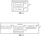
- FIG. 4 is a schematic diagram of components of a temperature control apparatus of a cookware in embodiments of the present application. As shown in FIG.4 , the temperature control apparatus 40 includes a first processor 401 and a first memory 402.
- the first processor 401 is configured to execute temperature control programs stored in the first memory 402 to implement the following steps:
- the temperature increase condition includes: the minimum temperature value being less than a lowest temperature threshold value, and the maximum temperature value being less than a highest temperature threshold value.
- the temperature reduction condition includes: the minimum temperature value being greater than or equal to a lowest temperature threshold value, or the maximum temperature value being greater than or equal to a highest temperature threshold value.
- the first processor 401 is configured to execute temperature control programs stored in the first memory 402 to implement the following steps: the lowest temperature threshold value and the highest temperature threshold value corresponding to each working mode of the cookware are preset; and the lowest temperature threshold value and the highest temperature threshold value of the cookware in the current working mode are determined.
- the cookware further includes: a second heating device to an N th heating device, and a plurality of temperature sensors arranged at different positions of an i th heating area.
- the i th heating area corresponds to an i th heating device, in which i is an integer of 2 to N.
- the first processor 401 is also configured to execute temperature control programs stored in the first memory 402 to implement the following steps: temperature values detected by the plurality of temperature sensors in the i th heating area are collected; a minimum temperature value and a maximum temperature value of the i th heating area are determined from all the collected temperature values; the i th heating device is started if the minimum temperature value and the maximum temperature value of the i th heating area satisfy the preset temperature increase condition; and the i th heating device is stopped if the minimum temperature value and the maximum temperature value of the i th heating area satisfy the preset temperature reduction condition.
- the first processor 401 is also configured to execute temperature control programs stored in the first memory 402 to implement the following steps: the lowest temperature threshold value and the highest temperature threshold value corresponding to each working mode of each heating area are preset; and the lowest temperature threshold value and the highest temperature threshold value of each heating area in the current working mode are determined.
- a distribution of the plurality of temperature sensors is a radial distribution or a dot matrix distribution.
- FIG.5 is a schematic diagram of components of a cookware in embodiments of the present application.
- the cookware 50 includes: a second processor 501, a second memory 502, a first heating device 503, and a plurality of temperature sensors 504 arranged at different positions of a first heating area.
- the second processor 501 is configured to execute temperature control programs stored in the second memory 502 to implement the following steps:
- the temperature increase condition includes: the minimum temperature value being less than a lowest temperature threshold value, and the maximum temperature value being less than a highest temperature threshold value.
- the temperature reduction condition includes: the minimum temperature value being greater than or equal to the lowest temperature threshold value, or the maximum temperature value being greater than or equal to the highest temperature threshold value.
- the second processor 501 is also configured to execute temperature control programs stored in the second memory 502 to implement the following steps: the lowest temperature threshold value and the highest temperature threshold value corresponding to each working mode of the cookware are preset; and the lowest temperature threshold value and the highest temperature threshold value of the cookware in the current working mode are determined.
- the cookware further includes: a second heating device to an N th heating device, and a plurality of temperature sensors arranged at different positions of an i th heating area.
- the i th heating area corresponds to an i th heating device, in which i is an integer of 2 to N.
- the second processor 501 is also configured to execute temperature control programs stored in the second memory 502 to implement the following steps: temperature values detected by the plurality of temperature sensors in the i th heating area are collected; a minimum temperature value and a maximum temperature value of the i th heating area are determined from all the collected temperature values; the i th heating device is started if the minimum temperature value and the maximum temperature value of the i th heating area satisfy the preset temperature increase condition; and the i th heating device is stopped if the minimum temperature value and the maximum temperature value of the i th heating area satisfy the preset temperature reduction condition.
- the second processor 501 is also configured to execute temperature control programs stored in the second memory 502 to implement the following steps: the lowest temperature threshold value and the highest temperature threshold value corresponding to each working mode of each heating area are preset; and the lowest temperature threshold value and the highest temperature threshold value of each heating area in the current working mode are determined.
- a distribution of the plurality of temperature sensors is a radial distribution or a dot matrix distribution.
- the above-mentioned first processor 401 and second processor 501 may be at least one of Application Specific Integrated Circuit (ASIC), Digital Signal Processing Device (DSPD), Programmable Logic Device (PLD), Field-Programmable Gate Array (FPGA), Micro Processor Unit (MPU) or Digital Signal Processor (DSP). It may be understood that, for different devices, the electronic elements used to implement the functions of the above-mentioned processors may also be other electronic elements, which are not specifically limited in the embodiments of the present application.
- ASIC Application Specific Integrated Circuit
- DSPD Digital Signal Processing Device
- PLD Programmable Logic Device
- FPGA Field-Programmable Gate Array
- MPU Micro Processor Unit
- DSP Digital Signal Processor
- Each of the above-mentioned first memory 402 and second memory 502 may be a volatile memory, such as a Random-Access Memory (RAM); or may be an non-volatile memory, such as a Read-Only Memory (ROM), a flash memory, a Hard Disk Drive (HDD) or a Solid-State Drive (SSD); or may be a combination of the above types of memories, and may provide instructions and data to the processors.
- RAM Random-Access Memory
- ROM Read-Only Memory
- HDD Hard Disk Drive
- SSD Solid-State Drive
- the embodiments of the present application further provide a computer readable storage medium.
- the computer readable storage medium is, for example, a first memory 402 having computer programs which may be executed by the first processor 401 of the temperature control apparatus, or a second memory 502 having computer programs which may be executed by the second processor 501 of the cookware, so that the steps of the method in one or more embodiments mentioned above are implemented.
- the embodiments of the present application may be provided as a method, a system, or a computer program product. Therefore, the present application may be in the form of hardware embodiments, software embodiments, or a combination thereof. Moreover, the present application may be in the form of a computer program product that is implemented on one or more computer-usable storage media (including, but not limited to, magnetic disk storage and optical storage) containing computer-usable program codes.
- a computer-usable storage media including, but not limited to, magnetic disk storage and optical storage
- each flow and/or block in the flow chart and/or the block diagram and the combination of flow and/or block in the flow chart and/or the block diagram may be realized via computer program instructions.
- Such computer program instructions may be provided to a processor of a general-purpose computer, a special-purpose computer, a built-in processor or other programmable data processing devices, to produce a machine, so that the instructions executed by the processor of the computer or other programmable data processing devices may produce a device for realizing the functions specified in one or more flows in the flow chart and/or one or more blocks in the block diagram.
- Such computer program instructions may also be stored in a computer-readable storage that can guide a computer or other programmable data processing devices to work in a specific mode, so that the instructions stored in the computer-readable storage may produce a manufacture including a command device.
- the command device may realize the functions specified in one or more flows of the flow chart and one or more blocks in the block diagram.
- Such computer program instructions may also be loaded to a computer or other programmable data processing devices, so that a series of operational processes may be executed on the computer or other programmable devices to produce a computer-realized processing, so that the instructions executed on the computer or other programmable devices may provide steps for realizing the functions specified in one or more flows in the flow chart and/or one or more blocks in the block diagram.
Landscapes
- Engineering & Computer Science (AREA)
- Food Science & Technology (AREA)
- Physics & Mathematics (AREA)
- General Physics & Mathematics (AREA)
- Automation & Control Theory (AREA)
- Remote Sensing (AREA)
- Electric Stoves And Ranges (AREA)
- Cookers (AREA)
- Induction Heating Cooking Devices (AREA)
Abstract
Description
- The present application is based upon and claims the benefit of priority from Chinese Patent Application No.
201810242383.1, filed on March 22, 2018 - The present application relates to the technology of temperature control, and in particular to a temperature control method and a temperature control apparatus for a cookware, a cookware and a storage medium.
- Temperature sensors of most existing baking machine are disposed at the center position of the baking tray, and the temperature sensors directly detect the temperature of the center of the baking tray. After preheating, a food is placed on the baking tray for cooking. When the food is just placed in a central region of the baking tray, since the food itself has a relatively low temperature, the food would absorb quickly the heat from the central region of the baking tray, thereby reducing the temperature of the central region of the baking tray. When the temperature sensors detect that the temperature of the baking tray has been reduced to the lowest temperature threshold value, a heating device is started to work, so that the working temperature of the baking tray is in a normal working range, so as to ensure the cooking effect of the food. However, when the food is placed on an edge region of the baking tray, the food would absorb the heat from the edge region of the baking tray, which has a little effect on the temperature of the center region of the baking tray in a short period of time, and thus the temperature sensors in the center region of the baking tray cannot detect the temperature reduction of the baking tray in time. Accordingly, the operation of the heating device cannot be controlled in time, so that the baking tray cannot provide a reliable cooking temperature for the food.
- The embodiments of the present application are expected to provide a temperature control method and a temperature control apparatus for a cookware, a cookware and a storage medium, to improve the flexibility of temperature control and improve the intelligent level of the cookware.
- The technical solutions of the present application are implemented as follows.
- The embodiments of the present application provide a temperature control method for a cookware, the cookware including a first heating device and a plurality of temperature sensors arranged at different positions of a first heating area; the method including the following steps:
- temperature values detected by the plurality of temperature sensors are collected;
- a minimum temperature value and a maximum temperature value of the first heating area are determined from all the collected temperature values;
- the first heating device is started if the minimum temperature value and the maximum temperature value of the first heating area satisfy a preset temperature increase condition; and
- the first heating device is stopped if the minimum temperature value and the maximum temperature value of the first heating area satisfy a preset temperature reduction condition.
- In the above solution, the temperature increase condition includes: the minimum temperature value being less than a lowest temperature threshold value, and the maximum temperature value being less than a highest temperature threshold value.
- In the above solution, the temperature reduction condition includes: the minimum temperature value being greater than or equal to a lowest temperature threshold value, or the maximum temperature value being greater than or equal to a highest temperature threshold value.
- In the above solution, the method further includes the following steps: the lowest temperature threshold value and the highest temperature threshold value corresponding to each working mode of the cookware are preset; and the lowest temperature threshold value and the highest temperature threshold value of the cookware in a current working mode are determined.
- In the above solution, the cookware further includes: a second heating device to an Nth heating device, and a plurality of temperature sensors arranged at different positions of an ith heating area. The ith heating area corresponds to an ith heating device, in which i is an integer of 2 to N. The method further includes the following steps: temperature values detected by the plurality of temperature sensors in the ith heating area are collected; a minimum temperature value and a maximum temperature value of the ith heating area are determined from all the collected temperature values; the ith heating device is started if the minimum temperature value and the maximum temperature value of the ith heating area satisfy the preset temperature increase condition; and the ith heating device is stopped if the minimum temperature value and the maximum temperature value of the ith heating area satisfy the preset temperature reduction condition.
- In the above solution, the method further includes the following steps: the lowest temperature threshold value and the highest temperature threshold value corresponding to each working mode of each heating area are preset; and the lowest temperature threshold value and the highest temperature threshold value of each heating area in a current working mode are determined.
- In the above solution, a distribution of the plurality of temperature sensors is a radial distribution or a dot matrix distribution.
- The embodiments of the present application further provide a temperature control apparatus for a cookware. The cookware includes a first heating device and a plurality of temperature sensors arranged at different positions of a first heating area. The temperature control apparatus includes a first processor and a first memory.
- The first processor is configured to execute temperature control programs stored in the first memory to implement the following steps: temperature values detected by the plurality of temperature sensors are collected; a minimum temperature value and a maximum temperature value of the first heating area are determined from all the collected temperature values; the first heating device is started if the minimum temperature value and the maximum temperature value of the first heating area satisfy a preset temperature increase condition; and the first heating device is stopped if the minimum temperature value and the maximum temperature value of the first heating area satisfy a preset temperature reduction condition.
- The embodiments of the present application further provide a cookware. The cookware includes a second processor, a second memory, a first heating device, and a plurality of temperature sensors arranged at different positions of a first heating area. The second processor is configured to execute temperature control programs stored in the second memory to implement the following steps:
- temperature values detected by the plurality of temperature sensors are collected;
- a minimum temperature value and a maximum temperature value of the first heating area are determined from all the collected temperature values;
- the first heating device is started if the minimum temperature value and the maximum temperature value of the first heating area satisfy a preset temperature increase condition; and
- the first heating device is stopped if the minimum temperature value and the maximum temperature value of the first heating area satisfy a preset temperature reduction condition.
- The embodiments of the present application further provide a computer readable storage medium having computer programs stored thereon, in which steps of the method of any one of the above embodiments are implemented when the computer programs are executed by a processor.
- The embodiments of the present application provide a temperature control method and a temperature control apparatus for a cookware, a cookware and a storage medium. The cookware includes a first heating device and a plurality of temperature sensors arranged at different positions of a first heating area. The method includes the following steps: temperature values detected by the plurality of temperature sensors are collected; a minimum temperature value and a maximum temperature value of the first heating area are determined from all the collected temperature values; the first heating device is started if the minimum temperature value and the maximum temperature value of the first heating area satisfy a preset temperature increase condition; and the first heating device is stopped if the minimum temperature value and the maximum temperature value of the first heating area satisfy a preset temperature reduction condition.
- By adopting the above technical solutions, the temperature of the heating area can be synthetically judged based on the temperature values detected by the plurality of temperature sensors. The heating device is started if the temperature increase condition is satisfied, so as to increase the temperature of the heating area to ensure the cooking effect of the food. The heating device is stopped if the temperature reduction condition is satisfied, so as to reduce the temperature of the heating area to ensure the safety of the cookware. In this way, the flexibility of temperature control is improved, and the intelligent level of the cookware is improved.
-
-
FIG. 1 is a flow chart of a first embodiment of a temperature control method for a cookware in embodiments of the present application; -
FIG. 2 is a schematic diagram of a structure of a cookware in embodiments of the present application; -
FIG. 3 is a flow chart of a second embodiment of a temperature control method for a cookware in embodiments of the present application; -
FIG. 4 is a schematic diagram of components of a temperature control apparatus of a cookware in embodiments of the present application; -
FIG. 5 is a schematic diagram of components of a cookware in embodiments of the present application. - Hereinafter, the technical solutions in the embodiments of the present application will be described clearly and completely in combination with the accompanying drawings in the embodiments of the present application.
- In the first embodiment, a cookware includes a first heating device and a plurality of temperature sensors arranged at different positions of a first heating area. Herein, the first heating device is configured to heat the first heating area, and the cookware may be a home kitchen appliance such as a baking machine, a steak machine, an induction cooker, a rice cooker and the like.
FIG. 1 is a flow chart of the first embodiment of a temperature control method for a cookware in embodiments of the present application. As shown inFIG. 1 , the method includes the following steps. - In
step 101, temperature values detected by the plurality of temperature sensors are collected. - As an example, when the heating area is a baking tray, the food is in contact with an outer surface of the baking tray, and the plurality of temperature sensors are in contact with an inner surface of the baking tray to detect the working temperature of the baking tray.
- Specifically, a distribution of the plurality of temperature sensors may be a radial distribution or a dot matrix distribution. The radial distribution includes a center position of the heating area and equally-spaced positions on a circumference of a circle that spreads outward from the center position by at least a radius. The dot matrix distribution includes a plurality of dot matrix positions with an equal row spacing and an equal column spacing.
-
FIG. 2 is a schematic diagram of structure of a cookware in embodiments of the present application. As shown inFIG.2 , the cookware is a baking machine. The bakingmachine 20 includes: abaking tray 201, aheating device 202 and a plurality oftemperature sensors 203, in which the baking tray is the heating area in the embodiments of the present application, and the food is placed on the baking tray to implement the cooking operation. The plurality oftemperature sensors 203, which are distributed in a radiation pattern, particularly include: a primary temperature sensor at the center position, and three secondary temperature sensors evenly distributed on a circumference of a circle that spreads outward from the center position by a radius. The primary temperature sensor is configured to detect the temperature at the center of the baking tray, and each of the three secondary temperature sensors is configured to detect the temperature at the edge of the baking tray. - In
step 102, a minimum temperature value and a maximum temperature value of the first heating area are determined from all the collected temperature values. - Herein, temperature values of the first heating area include T1, T2 to Tm. A number of m temperature values are compared to determine the minimum temperature value Tmin and the maximum temperature value Tmax. The two values can be used as a basis for controlling the starting and stopping of the first heating device, to improve the reliability of temperature control.
- In
step 103, the first heating device is started if the minimum temperature value and the maximum temperature value of the first heating area satisfy a preset temperature increase condition. - As an example, the temperature increase condition includes: the minimum temperature value being less than a lowest temperature threshold value, and the maximum temperature value being less than a highest temperature threshold value. Herein, before the first heating device is started, the first heating device is in a stopped state. Therefore, it is necessary to start the first heating device to increase the temperature of the first heating area.
- As an example, the first heating device may be an electrical heating tube, a heater with a Positive Temperature Coefficient (PCT) characteristic, or an electrical heating film, etc..
- In
step 104, the first heating device is stopped if the minimum temperature value and the maximum temperature value of the first heating area satisfy a preset temperature reduction condition. - As an example, the temperature reduction condition includes: the minimum temperature value being greater than or equal to a lowest temperature threshold value, or the maximum temperature value being greater than or equal to a highest temperature threshold value. Herein, before the first heating device is stopped, the first heating device is in a working state. Therefore, it is necessary to stop the first heating device to reduce the temperature of the first heating area.
- Optionally, the lowest temperature threshold value may be determined according to the minimum temperature value which guarantees the cooking effect of the food when the cookware is working, and the highest temperature threshold value may be determined according to the maximum temperature value which is allowed when the cookware is working. For example, since there are differences in sensitivities of the sensors and in temperatures of cooking ingredients, the range of the minimum temperature value may be set between 150 °C and 210 °C, preferably 180°C. In order to ensure that the baking machine works safely, a preset protection temperature of the baking tray is set between 250 °C and 300 °C, and the maximum temperature value may be 250 °C.
- In another optional embodiment, both the lowest temperature threshold value and the highest temperature threshold value may be determined according to a working mode selected in the cookware. For example, the cookware in a working mode has a corresponding temperature range. An upper limit value of the temperature range is the highest temperature threshold value and a lower limit value of the temperature range is the lowest temperature threshold value. For example, the working modes of the baking machine include: a steak mode, a pancake mode, a fried egg mode and the like. A temperature range corresponding to the steak mode is between 185 °C and 205 °C, in which the highest temperature threshold value is 205 °C, and the lowest temperature threshold value is 185 °C. A temperature range corresponding to the pancake mode is between 180 °C and 200 °C, in which the highest temperature threshold value is 200 °C, and the lowest temperature threshold value is 180 °C. A temperature range corresponding to the fried egg mode is between 170 °C and 190 °C, in which the highest temperature threshold value is 190 °C, and the lowest temperature threshold value is 170 °C.
- Thus, the temperature control method in the embodiment of the present application may further includes the following steps: the lowest temperature threshold value and the highest temperature threshold value corresponding to each working mode of the cookware are preset; and the lowest temperature threshold value and the highest temperature threshold value of the cookware in the current working mode are determined.
- In an actual implementation, the heating device is started, if Tmin is less than a preset lowest temperature threshold value TL and Tmax is less than a preset highest temperature threshold value TH; or else, the heating device is stopped, if Tmin is greater than or equal to the preset lowest temperature threshold value TL or Tmax is greater than or equal to the highest temperature threshold value TH. During the entire cooking process, cooking programs intermittently read the temperature values of all the temperature sensors, and judge whether to start or stop heating according to the above method until timing of the cooking program is over.
- In the embodiments of the present application,
step 101 to step 104 may be performed by a processor of the cookware, or performed by a processor of a temperature control apparatus for the cookware. The performing order ofstep 103 and step 104 as well as whether to performstep 103 and step 104 are not limited by the embodiments of the present application, but are determined based on the collected minimum temperature value and maximum temperature value. - In the embodiments of the present application, the cookware includes a first heating device and a plurality of temperature sensors arranged at different positions of a first heating area. The method includes the following steps: temperature values detected by the plurality of temperature sensors are collected; a minimum temperature value and a maximum temperature value of the first heating area are determined from all the collected temperature values; the first heating device is started if the minimum temperature value and the maximum temperature value of the first heating area satisfy a preset temperature increase condition; and the first heating device is stopped if the minimum temperature value and the maximum temperature value of the first heating area satisfy a preset temperature reduction condition.
- By adopting the above technical solutions, the temperature of the heating area can be synthetically judged based on the temperature values detected by the plurality of temperature sensors. The heating device is started if the temperature increase condition is satisfied, so as to increase the temperature of the heating area to ensure the cooking effect of the food. The heating device is stopped if the temperature reduction condition is satisfied, so as to reduce the temperature of the heating area to ensure the safety of the cookware. In this way, the flexibility of temperature control is improved, and the intelligent level of the cookware is improved.
- In order to better reflect the purpose of the present application, the present application is further exemplified on the basis of the first embodiment of the present application.
- In the second embodiment, the cookware includes: a first heating device, a second heating device to an Nth heating device, and a plurality of temperature sensors arranged at different positions of an ith heating area. The ith heating area corresponds to an ith heating device, in which i is an integer of 2 to N. The ith heating device is configured to heat the ith heating area. The ith heating device to the Nth heating device may be electrical heating tubes, heaters with PCT characteristic, or electrical heating films etc., and may be the same device or different devices.
-
FIG. 3 is a flow chart of the second embodiment of a temperature control method for a cookware in embodiments of the present application. The method includes the following steps. - In
step 301, temperature values detected by the plurality of temperature sensors are collected. - Herein, the temperature values detected by all of the temperature sensors on the cookware may be collected at the same time, or the temperature values detected by the temperature sensors in a part of the heating areas may be collected.
- In
step 302, a minimum temperature value and a maximum temperature value of the ith heating area are determined from all the collected temperature values. - Herein, the minimum temperature values and the maximum temperature values of the first heating area to the Nth heating area may be determined successively. The minimum temperature value and the maximum temperature value of each heating area may also be determined at the same time, and the heating device corresponding to each heating area may be controlled according to the determined maximum and minimum temperature values.
- In addition, the first heating area to the Nth heating area may be set flexibly according to the use of the cookware. For example, an upper baking tray of the baking machine is divided into several heating areas, or a lower baking tray of the baking machine is divided into several heating areas.
- In
step 303, it is judged whether the minimum temperature value and the maximum temperature value of the ith heating area satisfy the preset temperature increase condition. If it is,step 304 is performed; if it is not, step 305 is performed. - As an example, the temperature increase condition includes: the minimum temperature value of the ith heating area being less than a lowest temperature threshold value, and the maximum temperature value of the ith heating area being less than a highest temperature threshold value.
- In
step 304, the ith heating device is started. - After
step 304 is performed,step 301 is returned, so as to continue to collect temperature values detected by the plurality of temperature sensors at the next time, thereby achieving real-time monitoring of the temperature of the first heating area to the temperature of the Nth heating area. - In
step 305, it is judged whether the minimum temperature value and the maximum temperature value of the ith heating area satisfy the preset temperature reduction condition. If it is,step 306 is performed; if it is not, step 301 is returned. - As an example, the temperature reduction condition includes: the minimum temperature value of the ith heating area being greater than or equal to the lowest temperature threshold value, or the maximum temperature value of the ith heating area being greater than or equal to the highest temperature threshold value.
- In
step 306, the ith heating device is stopped. - After
step 306 is performed,step 301 is returned, so as to continue to collect temperature values detected by the plurality of temperature sensors at the next time, thereby achieving real-time monitoring of the temperature of the first heating area to the temperature of the Nth heating area until the cookware is stopped. Therefore, no matter which heating area the food is placed in, temperature change of the heating area may be detected in time, and heating is controlled according to the temperature change. In addition, the accuracy of temperature control in the heating areas may be improved by controlling independently starting and stopping of the plurality of heating devices. - Optionally, the lowest temperature threshold value and the highest temperature threshold value corresponding to each working mode of each heating area is preset; and the lowest temperature threshold value and the highest temperature threshold value of each heating area in the current working mode are determined.
- In the embodiment of the present application, a plurality of temperature sensors are arranged at different positions of the first heating area to the Nth heating area, to detect temperature values at different positions. In this way, no matter which one of the heating areas the food or the cooker is placed in, temperature change of the heating area may be detected in time, and starting or stopping of the heating device may be controlled according to the temperature change, so as to ensure that the heating area may provide a uniform temperature and improve the cooking effect.
- Based on the same inventive concept, the embodiments of the present application further provide a temperature control apparatus for a cookware. The cookware includes a first heating device and a plurality of temperature sensors arranged at different positions of a first heating area.
FIG. 4 is a schematic diagram of components of a temperature control apparatus of a cookware in embodiments of the present application. As shown inFIG.4 , thetemperature control apparatus 40 includes afirst processor 401 and afirst memory 402. - The
first processor 401 is configured to execute temperature control programs stored in thefirst memory 402 to implement the following steps: - temperature values detected by the plurality of temperature sensors are collected;
- a minimum temperature value and a maximum temperature value of the first heating area are determined from all the collected temperature values;
- the first heating device is started if the minimum temperature value and the maximum temperature value of the first heating area satisfy a preset temperature increase condition; and
- the first heating device is stopped if the minimum temperature value and the maximum temperature value of the first heating area satisfy a preset temperature reduction condition.
- In an actual implementation, the temperature increase condition includes: the minimum temperature value being less than a lowest temperature threshold value, and the maximum temperature value being less than a highest temperature threshold value.
- In an actual implementation, the temperature reduction condition includes: the minimum temperature value being greater than or equal to a lowest temperature threshold value, or the maximum temperature value being greater than or equal to a highest temperature threshold value.
- In an actual implementation, the
first processor 401 is configured to execute temperature control programs stored in thefirst memory 402 to implement the following steps: the lowest temperature threshold value and the highest temperature threshold value corresponding to each working mode of the cookware are preset; and the lowest temperature threshold value and the highest temperature threshold value of the cookware in the current working mode are determined. - In an actual implementation, the cookware further includes: a second heating device to an Nth heating device, and a plurality of temperature sensors arranged at different positions of an ith heating area. The ith heating area corresponds to an ith heating device, in which i is an integer of 2 to N. The
first processor 401 is also configured to execute temperature control programs stored in thefirst memory 402 to implement the following steps: temperature values detected by the plurality of temperature sensors in the ith heating area are collected; a minimum temperature value and a maximum temperature value of the ith heating area are determined from all the collected temperature values; the ith heating device is started if the minimum temperature value and the maximum temperature value of the ith heating area satisfy the preset temperature increase condition; and the ith heating device is stopped if the minimum temperature value and the maximum temperature value of the ith heating area satisfy the preset temperature reduction condition. - In an actual implementation, the
first processor 401 is also configured to execute temperature control programs stored in thefirst memory 402 to implement the following steps: the lowest temperature threshold value and the highest temperature threshold value corresponding to each working mode of each heating area are preset; and the lowest temperature threshold value and the highest temperature threshold value of each heating area in the current working mode are determined. - In an actual implementation, a distribution of the plurality of temperature sensors is a radial distribution or a dot matrix distribution.
- Based on the same inventive concept, the embodiments of the present application further provide a cookware.
FIG.5 is a schematic diagram of components of a cookware in embodiments of the present application. As shown inFIG.5 , thecookware 50 includes: asecond processor 501, asecond memory 502, afirst heating device 503, and a plurality oftemperature sensors 504 arranged at different positions of a first heating area. - The
second processor 501 is configured to execute temperature control programs stored in thesecond memory 502 to implement the following steps: - temperature values detected by the plurality of temperature sensors are collected;
- a minimum temperature value and a maximum temperature value of the first heating area are determined from all the collected temperature values;
- the first heating device is started if the minimum temperature value and the maximum temperature value of the first heating area satisfy a preset temperature increase condition; and
- the first heating device is stopped if the minimum temperature value and the maximum temperature value of the first heating area satisfy a preset temperature reduction condition.
- In an actual implementation, the temperature increase condition includes: the minimum temperature value being less than a lowest temperature threshold value, and the maximum temperature value being less than a highest temperature threshold value.
- In an actual implementation, the temperature reduction condition includes: the minimum temperature value being greater than or equal to the lowest temperature threshold value, or the maximum temperature value being greater than or equal to the highest temperature threshold value.
- In an actual implementation, the
second processor 501 is also configured to execute temperature control programs stored in thesecond memory 502 to implement the following steps: the lowest temperature threshold value and the highest temperature threshold value corresponding to each working mode of the cookware are preset; and the lowest temperature threshold value and the highest temperature threshold value of the cookware in the current working mode are determined. - In an actual implementation, the cookware further includes: a second heating device to an Nth heating device, and a plurality of temperature sensors arranged at different positions of an ith heating area. The ith heating area corresponds to an ith heating device, in which i is an integer of 2 to N. The
second processor 501 is also configured to execute temperature control programs stored in thesecond memory 502 to implement the following steps: temperature values detected by the plurality of temperature sensors in the ith heating area are collected; a minimum temperature value and a maximum temperature value of the ith heating area are determined from all the collected temperature values; the ith heating device is started if the minimum temperature value and the maximum temperature value of the ith heating area satisfy the preset temperature increase condition; and the ith heating device is stopped if the minimum temperature value and the maximum temperature value of the ith heating area satisfy the preset temperature reduction condition. - In an actual implementation, the
second processor 501 is also configured to execute temperature control programs stored in thesecond memory 502 to implement the following steps: the lowest temperature threshold value and the highest temperature threshold value corresponding to each working mode of each heating area are preset; and the lowest temperature threshold value and the highest temperature threshold value of each heating area in the current working mode are determined. - In an actual implementation, a distribution of the plurality of temperature sensors is a radial distribution or a dot matrix distribution.
- In an actual implementation, the above-mentioned
first processor 401 andsecond processor 501 may be at least one of Application Specific Integrated Circuit (ASIC), Digital Signal Processing Device (DSPD), Programmable Logic Device (PLD), Field-Programmable Gate Array (FPGA), Micro Processor Unit (MPU) or Digital Signal Processor (DSP). It may be understood that, for different devices, the electronic elements used to implement the functions of the above-mentioned processors may also be other electronic elements, which are not specifically limited in the embodiments of the present application. - Each of the above-mentioned
first memory 402 andsecond memory 502 may be a volatile memory, such as a Random-Access Memory (RAM); or may be an non-volatile memory, such as a Read-Only Memory (ROM), a flash memory, a Hard Disk Drive (HDD) or a Solid-State Drive (SSD); or may be a combination of the above types of memories, and may provide instructions and data to the processors. - Based on the same inventive concept, the embodiments of the present application further provide a computer readable storage medium. The computer readable storage medium is, for example, a
first memory 402 having computer programs which may be executed by thefirst processor 401 of the temperature control apparatus, or asecond memory 502 having computer programs which may be executed by thesecond processor 501 of the cookware, so that the steps of the method in one or more embodiments mentioned above are implemented. - One skilled in the art should understand that, the embodiments of the present application may be provided as a method, a system, or a computer program product. Therefore, the present application may be in the form of hardware embodiments, software embodiments, or a combination thereof. Moreover, the present application may be in the form of a computer program product that is implemented on one or more computer-usable storage media (including, but not limited to, magnetic disk storage and optical storage) containing computer-usable program codes.
- The present application is described referring to the flow chart and/or block diagram of the method, device (system) and computer program product according to the embodiments of the present application. It should be understood that, each flow and/or block in the flow chart and/or the block diagram and the combination of flow and/or block in the flow chart and/or the block diagram may be realized via computer program instructions. Such computer program instructions may be provided to a processor of a general-purpose computer, a special-purpose computer, a built-in processor or other programmable data processing devices, to produce a machine, so that the instructions executed by the processor of the computer or other programmable data processing devices may produce a device for realizing the functions specified in one or more flows in the flow chart and/or one or more blocks in the block diagram.
- Such computer program instructions may also be stored in a computer-readable storage that can guide a computer or other programmable data processing devices to work in a specific mode, so that the instructions stored in the computer-readable storage may produce a manufacture including a command device. The command device may realize the functions specified in one or more flows of the flow chart and one or more blocks in the block diagram.
- Such computer program instructions may also be loaded to a computer or other programmable data processing devices, so that a series of operational processes may be executed on the computer or other programmable devices to produce a computer-realized processing, so that the instructions executed on the computer or other programmable devices may provide steps for realizing the functions specified in one or more flows in the flow chart and/or one or more blocks in the block diagram.
- The above embodiments are only preferred embodiments of the present application and are not intended to limit the protection scope of the present application.
Claims (10)
- A temperature control method for a cookware, the cookware comprising a first heating device and a plurality of temperature sensors arranged at different positions of a first heating area, the method comprising:collecting temperature values detected by the plurality of temperature sensors;determining a minimum temperature value and a maximum temperature value of the first heating area from all the collected temperature values;starting the first heating device if the minimum temperature value and the maximum temperature value of the first heating area satisfy a preset temperature increase condition; andstopping the first heating device if the minimum temperature value and the maximum temperature value of the first heating area satisfy a preset temperature reduction condition.
- The method of claim 1, wherein the temperature increase condition comprises: the minimum temperature value being less than a lowest temperature threshold value, and the maximum temperature value being less than a highest temperature threshold value.
- The method of claim 1, wherein the temperature reduction condition comprises: the minimum temperature value being greater than or equal to a lowest temperature threshold value, or the maximum temperature value being greater than or equal to a highest temperature threshold value.
- The method of claim 2 or 3, wherein the method further comprises:presetting the lowest temperature threshold value and the highest temperature threshold value corresponding to each working mode of the cookware; anddetermining the lowest temperature threshold value and the highest temperature threshold value of the cookware in a current operating mode.
- The method of claim 2 or 3, wherein the cookware further comprises: a second heating device to an Nth heating device, and a plurality of temperature sensors arranged at different positions of an ith heating area; wherein the ith heating area corresponds to an ith heating device, in which i is an integer from 2 to N; the method further comprises:collecting temperature values detected by the plurality of temperature sensors in the ith heating area;determining a minimum temperature value and a maximum temperature value of the ith heating area from all the collected temperature values;starting the ith heating device if the minimum temperature value and the maximum temperature value of the ith heating area satisfy the preset temperature increase condition; andstopping the ith heating device if the minimum temperature value and the maximum temperature value of the ith heating area satisfy the preset temperature reduction condition.
- The method of claim 5, wherein the method further comprises:presetting the lowest temperature threshold value and the highest temperature threshold value corresponding to each operating mode of each heating area; anddetermining the lowest temperature threshold value and the highest temperature threshold value of each heating area in a current operating mode.
- The method of claim 1, wherein a distribution of the plurality of temperature sensors is a radial distribution or a dot matrix distribution.
- A temperature control apparatus for a cookware, the cookware comprising a first heating device and a plurality of temperature sensors arranged at different positions of a first heating area; the temperature control apparatus comprising: a first processor and a first memory; wherein
the first processor is configured to execute temperature control programs stored in the first memory to implement the following steps:collecting temperature values detected by the plurality of temperature sensors;determining a minimum temperature value and a maximum temperature value of the first heating area from all the collected temperature values;starting the first heating device if the minimum temperature value and the maximum temperature value of the first heating area satisfy a preset temperature increase condition; andstopping the first heating device if the minimum temperature value and the maximum temperature value of the first heating area satisfy a preset temperature reduction condition. - A cookware comprising a second processor, a second memory, a first heating device, and a plurality of temperature sensors arranged at different positions of a first heating area; wherein
the second processor is configured to execute temperature control programs stored in the second memory to implement the following steps:collecting temperature values detected by the plurality of temperature sensors;determining a minimum temperature value and a maximum temperature value of the first heating area from all the collected temperature values;starting the first heating device if the minimum temperature value and the maximum temperature value of the first heating area satisfy a preset temperature increase condition; andstopping the first heating device if the minimum temperature value and the maximum temperature value of the first heating area satisfy a preset temperature reduction condition. - A computer readable storage medium having computer programs stored thereon, wherein steps of the method of any one of claims 1 to 7 are implemented when the computer programs are executed by a processor.
Applications Claiming Priority (2)
| Application Number | Priority Date | Filing Date | Title |
|---|---|---|---|
| CN201810242383.1A CN110297512B (en) | 2018-03-22 | 2018-03-22 | Temperature control method and device for cooking appliance, cooking appliance and storage medium |
| PCT/CN2018/102488 WO2019179038A1 (en) | 2018-03-22 | 2018-08-27 | Temperature control method and apparatus for cookware, and cookware and storage medium |
Publications (3)
| Publication Number | Publication Date |
|---|---|
| EP3754453A1 true EP3754453A1 (en) | 2020-12-23 |
| EP3754453A4 EP3754453A4 (en) | 2021-03-17 |
| EP3754453B1 EP3754453B1 (en) | 2023-12-27 |
Family
ID=67988286
Family Applications (1)
| Application Number | Title | Priority Date | Filing Date |
|---|---|---|---|
| EP18910968.9A Active EP3754453B1 (en) | 2018-03-22 | 2018-08-27 | Temperature control method and apparatus for cookware, and cookware and storage medium |
Country Status (4)
| Country | Link |
|---|---|
| US (1) | US20210015298A1 (en) |
| EP (1) | EP3754453B1 (en) |
| CN (1) | CN110297512B (en) |
| WO (1) | WO2019179038A1 (en) |
Families Citing this family (9)
| Publication number | Priority date | Publication date | Assignee | Title |
|---|---|---|---|---|
| US11422037B2 (en) | 2018-03-15 | 2022-08-23 | Brava Home, Inc. | Temperature probe systems and methods |
| CN111897381B (en) * | 2020-07-30 | 2021-08-20 | 珠海格力电器股份有限公司 | Oven control method and device and oven |
| CN114451791A (en) * | 2020-11-09 | 2022-05-10 | 烟台欣和企业食品有限公司 | Frying cooking method and apparatus |
| CN116135091B (en) * | 2021-11-18 | 2025-07-25 | 珠海优特智厨科技有限公司 | Temperature control device and method |
| CN114287805A (en) * | 2021-12-14 | 2022-04-08 | 广东美的厨房电器制造有限公司 | Baking tray and oven |
| CN116456519B (en) * | 2022-12-30 | 2026-02-17 | 浙江绍兴苏泊尔生活电器有限公司 | Heating control method, controller and induction cooker |
| CN117045129A (en) * | 2023-07-28 | 2023-11-14 | 珠海优特智厨科技有限公司 | Control method, device, cooking equipment and readable storage medium for cooking equipment |
| CN119699884A (en) * | 2023-09-27 | 2025-03-28 | 佛山市顺德区美的电热电器制造有限公司 | Cooking appliance control method, device and cooking appliance |
| CN118633849B (en) * | 2024-08-14 | 2024-11-26 | 杭州欧歌电器有限公司 | Heating control method and system of frying and roasting equipment |
Family Cites Families (20)
| Publication number | Priority date | Publication date | Assignee | Title |
|---|---|---|---|---|
| US5365039A (en) * | 1992-07-21 | 1994-11-15 | Hatco Corporation | Humidity controlled food warmer |
| CN1082662C (en) * | 1995-09-25 | 2002-04-10 | Lg电子株式会社 | Temperature measuring apparatus and method using thermopile sensor |
| JPH10141669A (en) * | 1996-11-12 | 1998-05-29 | Sharp Corp | Thaw control method |
| JP3983304B2 (en) * | 1997-05-29 | 2007-09-26 | コーニンクレッカ フィリップス エレクトロニクス エヌ ヴィ | Heating element |
| JPH11182851A (en) * | 1997-12-22 | 1999-07-06 | Matsushita Electric Ind Co Ltd | Heating equipment |
| US6834160B1 (en) * | 2003-11-14 | 2004-12-21 | Huang Chen-Lung | Electric heater with a sensor preventing no-water heating |
| US20070034096A1 (en) * | 2005-07-13 | 2007-02-15 | Hyperion Innovations, Inc. | Method and apparatus for maintaining an elevated food temperature |
| JP2009259740A (en) * | 2008-04-21 | 2009-11-05 | Toshiba Corp | Induction heat cooking system |
| CN101751055A (en) * | 2008-12-04 | 2010-06-23 | 乐金电子(天津)电器有限公司 | Food unfreezing method of microwave oven |
| FR2966002B1 (en) * | 2010-10-07 | 2015-12-11 | Fagorbrandt Sas | METHOD FOR OPERATING CONTROL OF INDUCTOR ASSEMBLY OF INDUCTION COOKTOP AND INDUCTION COOKTOP THEREFOR |
| JP6117720B2 (en) * | 2013-04-19 | 2017-04-19 | 三菱電機株式会社 | Induction heating cooker |
| CN203302906U (en) * | 2013-06-17 | 2013-11-27 | 金文杰 | Temperature-controlled smokeless electric oven |
| US20170318629A1 (en) * | 2014-06-05 | 2017-11-02 | Younes Mohseni | Multifunction Ovens |
| CN105326334A (en) * | 2015-12-02 | 2016-02-17 | 米技电子电器(上海)有限公司 | Cooker with cooker bottom temperature sensors |
| JP6602217B2 (en) * | 2016-02-03 | 2019-11-06 | 三菱電機株式会社 | Cooker |
| CN105972650A (en) * | 2016-05-05 | 2016-09-28 | 广东美的厨房电器制造有限公司 | Low-temperature microwave cooking method, low-temperature microwave cooking system and microwave heating device |
| CN105942880A (en) * | 2016-06-21 | 2016-09-21 | 广东美的厨房电器制造有限公司 | Cooking method, cooking system and cooking device |
| CN206137862U (en) * | 2016-07-20 | 2017-05-03 | 佛山市顺德区美的电热电器制造有限公司 | Intelligence culinary art controlling means |
| CN107411540B (en) * | 2017-08-30 | 2022-09-02 | 浙江绍兴苏泊尔生活电器有限公司 | Cooker, induction cooker, cooker assembly and information indication method |
| CN107660995B (en) * | 2017-10-31 | 2020-06-05 | 博脉有限公司 | Smart cookware and smart cookware set |
-
2018
- 2018-03-22 CN CN201810242383.1A patent/CN110297512B/en active Active
- 2018-08-27 WO PCT/CN2018/102488 patent/WO2019179038A1/en not_active Ceased
- 2018-08-27 US US17/040,021 patent/US20210015298A1/en active Pending
- 2018-08-27 EP EP18910968.9A patent/EP3754453B1/en active Active
Also Published As
| Publication number | Publication date |
|---|---|
| EP3754453B1 (en) | 2023-12-27 |
| CN110297512A (en) | 2019-10-01 |
| WO2019179038A1 (en) | 2019-09-26 |
| EP3754453A4 (en) | 2021-03-17 |
| CN110297512B (en) | 2021-07-20 |
| US20210015298A1 (en) | 2021-01-21 |
Similar Documents
| Publication | Publication Date | Title |
|---|---|---|
| EP3754453B1 (en) | Temperature control method and apparatus for cookware, and cookware and storage medium | |
| CN104274087B (en) | Baking machine and its method for heating and controlling | |
| CN106304453A (en) | Food heating control method, device and cooking appliance including the device | |
| CN113475945B (en) | Cooking control method and device of cooking appliance, storage medium and cooking appliance | |
| CN110074667B (en) | Boiling detection method and boiling detection device, readable storage medium and cooking equipment | |
| CN110726159A (en) | Heating control method, cooking utensil and system and computer readable storage medium | |
| CN105078233A (en) | Electric cooker and control method thereof | |
| WO2021204235A1 (en) | Fire turn-off detection method and apparatus for cooking device, and range hood and storage medium | |
| CN105380513A (en) | Electric pressure cooker and heating control method and device thereof | |
| CN108614597B (en) | Heating control method and apparatus for cooking utensils, and cooking utensils | |
| CN110089931B (en) | Pressure cooking appliance and control method thereof | |
| WO2019080197A1 (en) | Food cooking control method and device, and storage medium | |
| CN113133665B (en) | Dry burning prevention detection method for cooking utensil and cooking utensil | |
| CN116456519B (en) | Heating control method, controller and induction cooker | |
| CN106308465A (en) | Method for recognizing cooking type of electric cooker and electric cooker | |
| CN107752713B (en) | A kind of control method and system for rice cooker cooking | |
| CN116614910B (en) | Induction cooker control method, system, terminal equipment and storage medium | |
| CN115059940B (en) | Detection method and device of electromagnetic heating appliance and electronic equipment | |
| CN110933795A (en) | Microwave oven, control method and device thereof and storage medium | |
| CN111053440A (en) | Cooking control method and device and electric stewpan | |
| CN110671726A (en) | Temperature control method, cooking utensil, cooking system and computer readable storage medium | |
| CN117397996A (en) | Juice collection control method of cooking appliance, cooking appliance and storage medium | |
| CN117091170A (en) | Anti-dry burning control method, device, heating equipment and storage medium | |
| JP5218287B2 (en) | Induction heating cooker | |
| CN114532861A (en) | Food processing machine and dry burning prevention control method thereof |
Legal Events
| Date | Code | Title | Description |
|---|---|---|---|
| STAA | Information on the status of an ep patent application or granted ep patent |
Free format text: STATUS: THE INTERNATIONAL PUBLICATION HAS BEEN MADE |
|
| PUAI | Public reference made under article 153(3) epc to a published international application that has entered the european phase |
Free format text: ORIGINAL CODE: 0009012 |
|
| STAA | Information on the status of an ep patent application or granted ep patent |
Free format text: STATUS: REQUEST FOR EXAMINATION WAS MADE |
|
| 17P | Request for examination filed |
Effective date: 20200917 |
|
| AK | Designated contracting states |
Kind code of ref document: A1 Designated state(s): AL AT BE BG CH CY CZ DE DK EE ES FI FR GB GR HR HU IE IS IT LI LT LU LV MC MK MT NL NO PL PT RO RS SE SI SK SM TR |
|
| AX | Request for extension of the european patent |
Extension state: BA ME |
|
| A4 | Supplementary search report drawn up and despatched |
Effective date: 20210211 |
|
| RIC1 | Information provided on ipc code assigned before grant |
Ipc: G05D 23/00 20060101AFI20210205BHEP Ipc: G05D 23/20 20060101ALI20210205BHEP |
|
| DAV | Request for validation of the european patent (deleted) | ||
| DAX | Request for extension of the european patent (deleted) | ||
| STAA | Information on the status of an ep patent application or granted ep patent |
Free format text: STATUS: EXAMINATION IS IN PROGRESS |
|
| 17Q | First examination report despatched |
Effective date: 20211125 |
|
| GRAP | Despatch of communication of intention to grant a patent |
Free format text: ORIGINAL CODE: EPIDOSNIGR1 |
|
| STAA | Information on the status of an ep patent application or granted ep patent |
Free format text: STATUS: GRANT OF PATENT IS INTENDED |
|
| GRAS | Grant fee paid |
Free format text: ORIGINAL CODE: EPIDOSNIGR3 |
|
| INTG | Intention to grant announced |
Effective date: 20231026 |
|
| GRAA | (expected) grant |
Free format text: ORIGINAL CODE: 0009210 |
|
| STAA | Information on the status of an ep patent application or granted ep patent |
Free format text: STATUS: THE PATENT HAS BEEN GRANTED |
|
| AK | Designated contracting states |
Kind code of ref document: B1 Designated state(s): AL AT BE BG CH CY CZ DE DK EE ES FI FR GB GR HR HU IE IS IT LI LT LU LV MC MK MT NL NO PL PT RO RS SE SI SK SM TR |
|
| REG | Reference to a national code |
Ref country code: GB Ref legal event code: FG4D |
|
| REG | Reference to a national code |
Ref country code: CH Ref legal event code: EP |
|
| REG | Reference to a national code |
Ref country code: DE Ref legal event code: R096 Ref document number: 602018063449 Country of ref document: DE |
|
| REG | Reference to a national code |
Ref country code: IE Ref legal event code: FG4D |
|
| PG25 | Lapsed in a contracting state [announced via postgrant information from national office to epo] |
Ref country code: GR Free format text: LAPSE BECAUSE OF FAILURE TO SUBMIT A TRANSLATION OF THE DESCRIPTION OR TO PAY THE FEE WITHIN THE PRESCRIBED TIME-LIMIT Effective date: 20240328 |
|
| REG | Reference to a national code |
Ref country code: LT Ref legal event code: MG9D |
|
| PG25 | Lapsed in a contracting state [announced via postgrant information from national office to epo] |
Ref country code: LT Free format text: LAPSE BECAUSE OF FAILURE TO SUBMIT A TRANSLATION OF THE DESCRIPTION OR TO PAY THE FEE WITHIN THE PRESCRIBED TIME-LIMIT Effective date: 20231227 |
|
| PG25 | Lapsed in a contracting state [announced via postgrant information from national office to epo] |
Ref country code: ES Free format text: LAPSE BECAUSE OF FAILURE TO SUBMIT A TRANSLATION OF THE DESCRIPTION OR TO PAY THE FEE WITHIN THE PRESCRIBED TIME-LIMIT Effective date: 20231227 |
|
| PG25 | Lapsed in a contracting state [announced via postgrant information from national office to epo] |
Ref country code: LT Free format text: LAPSE BECAUSE OF FAILURE TO SUBMIT A TRANSLATION OF THE DESCRIPTION OR TO PAY THE FEE WITHIN THE PRESCRIBED TIME-LIMIT Effective date: 20231227 Ref country code: GR Free format text: LAPSE BECAUSE OF FAILURE TO SUBMIT A TRANSLATION OF THE DESCRIPTION OR TO PAY THE FEE WITHIN THE PRESCRIBED TIME-LIMIT Effective date: 20240328 Ref country code: FI Free format text: LAPSE BECAUSE OF FAILURE TO SUBMIT A TRANSLATION OF THE DESCRIPTION OR TO PAY THE FEE WITHIN THE PRESCRIBED TIME-LIMIT Effective date: 20231227 Ref country code: ES Free format text: LAPSE BECAUSE OF FAILURE TO SUBMIT A TRANSLATION OF THE DESCRIPTION OR TO PAY THE FEE WITHIN THE PRESCRIBED TIME-LIMIT Effective date: 20231227 Ref country code: BG Free format text: LAPSE BECAUSE OF FAILURE TO SUBMIT A TRANSLATION OF THE DESCRIPTION OR TO PAY THE FEE WITHIN THE PRESCRIBED TIME-LIMIT Effective date: 20240327 |
|
| REG | Reference to a national code |
Ref country code: NL Ref legal event code: MP Effective date: 20231227 |
|
| REG | Reference to a national code |
Ref country code: AT Ref legal event code: MK05 Ref document number: 1645126 Country of ref document: AT Kind code of ref document: T Effective date: 20231227 |
|
| PG25 | Lapsed in a contracting state [announced via postgrant information from national office to epo] |
Ref country code: NL Free format text: LAPSE BECAUSE OF FAILURE TO SUBMIT A TRANSLATION OF THE DESCRIPTION OR TO PAY THE FEE WITHIN THE PRESCRIBED TIME-LIMIT Effective date: 20231227 |
|
| PG25 | Lapsed in a contracting state [announced via postgrant information from national office to epo] |
Ref country code: SE Free format text: LAPSE BECAUSE OF FAILURE TO SUBMIT A TRANSLATION OF THE DESCRIPTION OR TO PAY THE FEE WITHIN THE PRESCRIBED TIME-LIMIT Effective date: 20231227 Ref country code: RS Free format text: LAPSE BECAUSE OF FAILURE TO SUBMIT A TRANSLATION OF THE DESCRIPTION OR TO PAY THE FEE WITHIN THE PRESCRIBED TIME-LIMIT Effective date: 20231227 Ref country code: NO Free format text: LAPSE BECAUSE OF FAILURE TO SUBMIT A TRANSLATION OF THE DESCRIPTION OR TO PAY THE FEE WITHIN THE PRESCRIBED TIME-LIMIT Effective date: 20240327 Ref country code: NL Free format text: LAPSE BECAUSE OF FAILURE TO SUBMIT A TRANSLATION OF THE DESCRIPTION OR TO PAY THE FEE WITHIN THE PRESCRIBED TIME-LIMIT Effective date: 20231227 Ref country code: LV Free format text: LAPSE BECAUSE OF FAILURE TO SUBMIT A TRANSLATION OF THE DESCRIPTION OR TO PAY THE FEE WITHIN THE PRESCRIBED TIME-LIMIT Effective date: 20231227 Ref country code: HR Free format text: LAPSE BECAUSE OF FAILURE TO SUBMIT A TRANSLATION OF THE DESCRIPTION OR TO PAY THE FEE WITHIN THE PRESCRIBED TIME-LIMIT Effective date: 20231227 |
|
| PG25 | Lapsed in a contracting state [announced via postgrant information from national office to epo] |
Ref country code: IS Free format text: LAPSE BECAUSE OF FAILURE TO SUBMIT A TRANSLATION OF THE DESCRIPTION OR TO PAY THE FEE WITHIN THE PRESCRIBED TIME-LIMIT Effective date: 20240427 |
|
| PG25 | Lapsed in a contracting state [announced via postgrant information from national office to epo] |
Ref country code: AT Free format text: LAPSE BECAUSE OF FAILURE TO SUBMIT A TRANSLATION OF THE DESCRIPTION OR TO PAY THE FEE WITHIN THE PRESCRIBED TIME-LIMIT Effective date: 20231227 Ref country code: CZ Free format text: LAPSE BECAUSE OF FAILURE TO SUBMIT A TRANSLATION OF THE DESCRIPTION OR TO PAY THE FEE WITHIN THE PRESCRIBED TIME-LIMIT Effective date: 20231227 |
|
| PG25 | Lapsed in a contracting state [announced via postgrant information from national office to epo] |
Ref country code: SK Free format text: LAPSE BECAUSE OF FAILURE TO SUBMIT A TRANSLATION OF THE DESCRIPTION OR TO PAY THE FEE WITHIN THE PRESCRIBED TIME-LIMIT Effective date: 20231227 |
|
| PG25 | Lapsed in a contracting state [announced via postgrant information from national office to epo] |
Ref country code: SM Free format text: LAPSE BECAUSE OF FAILURE TO SUBMIT A TRANSLATION OF THE DESCRIPTION OR TO PAY THE FEE WITHIN THE PRESCRIBED TIME-LIMIT Effective date: 20231227 Ref country code: SK Free format text: LAPSE BECAUSE OF FAILURE TO SUBMIT A TRANSLATION OF THE DESCRIPTION OR TO PAY THE FEE WITHIN THE PRESCRIBED TIME-LIMIT Effective date: 20231227 Ref country code: RO Free format text: LAPSE BECAUSE OF FAILURE TO SUBMIT A TRANSLATION OF THE DESCRIPTION OR TO PAY THE FEE WITHIN THE PRESCRIBED TIME-LIMIT Effective date: 20231227 Ref country code: IT Free format text: LAPSE BECAUSE OF FAILURE TO SUBMIT A TRANSLATION OF THE DESCRIPTION OR TO PAY THE FEE WITHIN THE PRESCRIBED TIME-LIMIT Effective date: 20231227 Ref country code: IS Free format text: LAPSE BECAUSE OF FAILURE TO SUBMIT A TRANSLATION OF THE DESCRIPTION OR TO PAY THE FEE WITHIN THE PRESCRIBED TIME-LIMIT Effective date: 20240427 Ref country code: EE Free format text: LAPSE BECAUSE OF FAILURE TO SUBMIT A TRANSLATION OF THE DESCRIPTION OR TO PAY THE FEE WITHIN THE PRESCRIBED TIME-LIMIT Effective date: 20231227 Ref country code: CZ Free format text: LAPSE BECAUSE OF FAILURE TO SUBMIT A TRANSLATION OF THE DESCRIPTION OR TO PAY THE FEE WITHIN THE PRESCRIBED TIME-LIMIT Effective date: 20231227 Ref country code: AT Free format text: LAPSE BECAUSE OF FAILURE TO SUBMIT A TRANSLATION OF THE DESCRIPTION OR TO PAY THE FEE WITHIN THE PRESCRIBED TIME-LIMIT Effective date: 20231227 |
|
| PG25 | Lapsed in a contracting state [announced via postgrant information from national office to epo] |
Ref country code: PT Free format text: LAPSE BECAUSE OF FAILURE TO SUBMIT A TRANSLATION OF THE DESCRIPTION OR TO PAY THE FEE WITHIN THE PRESCRIBED TIME-LIMIT Effective date: 20240429 Ref country code: PL Free format text: LAPSE BECAUSE OF FAILURE TO SUBMIT A TRANSLATION OF THE DESCRIPTION OR TO PAY THE FEE WITHIN THE PRESCRIBED TIME-LIMIT Effective date: 20231227 |
|
| PG25 | Lapsed in a contracting state [announced via postgrant information from national office to epo] |
Ref country code: PT Free format text: LAPSE BECAUSE OF FAILURE TO SUBMIT A TRANSLATION OF THE DESCRIPTION OR TO PAY THE FEE WITHIN THE PRESCRIBED TIME-LIMIT Effective date: 20240429 Ref country code: PL Free format text: LAPSE BECAUSE OF FAILURE TO SUBMIT A TRANSLATION OF THE DESCRIPTION OR TO PAY THE FEE WITHIN THE PRESCRIBED TIME-LIMIT Effective date: 20231227 |
|
| REG | Reference to a national code |
Ref country code: DE Ref legal event code: R097 Ref document number: 602018063449 Country of ref document: DE |
|
| PG25 | Lapsed in a contracting state [announced via postgrant information from national office to epo] |
Ref country code: DK Free format text: LAPSE BECAUSE OF FAILURE TO SUBMIT A TRANSLATION OF THE DESCRIPTION OR TO PAY THE FEE WITHIN THE PRESCRIBED TIME-LIMIT Effective date: 20231227 |
|
| PG25 | Lapsed in a contracting state [announced via postgrant information from national office to epo] |
Ref country code: DK Free format text: LAPSE BECAUSE OF FAILURE TO SUBMIT A TRANSLATION OF THE DESCRIPTION OR TO PAY THE FEE WITHIN THE PRESCRIBED TIME-LIMIT Effective date: 20231227 |
|
| PLBE | No opposition filed within time limit |
Free format text: ORIGINAL CODE: 0009261 |
|
| STAA | Information on the status of an ep patent application or granted ep patent |
Free format text: STATUS: NO OPPOSITION FILED WITHIN TIME LIMIT |
|
| 26N | No opposition filed |
Effective date: 20240930 |
|
| REG | Reference to a national code |
Ref country code: CH Ref legal event code: PL |
|
| PG25 | Lapsed in a contracting state [announced via postgrant information from national office to epo] |
Ref country code: LU Free format text: LAPSE BECAUSE OF NON-PAYMENT OF DUE FEES Effective date: 20240827 |
|
| PG25 | Lapsed in a contracting state [announced via postgrant information from national office to epo] |
Ref country code: MC Free format text: LAPSE BECAUSE OF FAILURE TO SUBMIT A TRANSLATION OF THE DESCRIPTION OR TO PAY THE FEE WITHIN THE PRESCRIBED TIME-LIMIT Effective date: 20231227 Ref country code: CH Free format text: LAPSE BECAUSE OF NON-PAYMENT OF DUE FEES Effective date: 20240831 Ref country code: SI Free format text: LAPSE BECAUSE OF FAILURE TO SUBMIT A TRANSLATION OF THE DESCRIPTION OR TO PAY THE FEE WITHIN THE PRESCRIBED TIME-LIMIT Effective date: 20231227 |
|
| REG | Reference to a national code |
Ref country code: BE Ref legal event code: MM Effective date: 20240831 |
|
| PG25 | Lapsed in a contracting state [announced via postgrant information from national office to epo] |
Ref country code: BE Free format text: LAPSE BECAUSE OF NON-PAYMENT OF DUE FEES Effective date: 20240831 |
|
| PG25 | Lapsed in a contracting state [announced via postgrant information from national office to epo] |
Ref country code: IE Free format text: LAPSE BECAUSE OF NON-PAYMENT OF DUE FEES Effective date: 20240827 |
|
| PGFP | Annual fee paid to national office [announced via postgrant information from national office to epo] |
Ref country code: DE Payment date: 20250827 Year of fee payment: 8 |
|
| PGFP | Annual fee paid to national office [announced via postgrant information from national office to epo] |
Ref country code: GB Payment date: 20250826 Year of fee payment: 8 |
|
| PGFP | Annual fee paid to national office [announced via postgrant information from national office to epo] |
Ref country code: FR Payment date: 20250826 Year of fee payment: 8 |
|
| PG25 | Lapsed in a contracting state [announced via postgrant information from national office to epo] |
Ref country code: CY Free format text: LAPSE BECAUSE OF FAILURE TO SUBMIT A TRANSLATION OF THE DESCRIPTION OR TO PAY THE FEE WITHIN THE PRESCRIBED TIME-LIMIT; INVALID AB INITIO Effective date: 20180827 |
|
| PG25 | Lapsed in a contracting state [announced via postgrant information from national office to epo] |
Ref country code: HU Free format text: LAPSE BECAUSE OF FAILURE TO SUBMIT A TRANSLATION OF THE DESCRIPTION OR TO PAY THE FEE WITHIN THE PRESCRIBED TIME-LIMIT; INVALID AB INITIO Effective date: 20180827 |