EP3754364A1 - Laser radar device - Google Patents
Laser radar device Download PDFInfo
- Publication number
- EP3754364A1 EP3754364A1 EP18911713.8A EP18911713A EP3754364A1 EP 3754364 A1 EP3754364 A1 EP 3754364A1 EP 18911713 A EP18911713 A EP 18911713A EP 3754364 A1 EP3754364 A1 EP 3754364A1
- Authority
- EP
- European Patent Office
- Prior art keywords
- optical
- light
- laser radar
- signal
- radar device
- Prior art date
- Legal status (The legal status is an assumption and is not a legal conclusion. Google has not performed a legal analysis and makes no representation as to the accuracy of the status listed.)
- Granted
Links
Images


Classifications
-
- G—PHYSICS
- G01—MEASURING; TESTING
- G01S—RADIO DIRECTION-FINDING; RADIO NAVIGATION; DETERMINING DISTANCE OR VELOCITY BY USE OF RADIO WAVES; LOCATING OR PRESENCE-DETECTING BY USE OF THE REFLECTION OR RERADIATION OF RADIO WAVES; ANALOGOUS ARRANGEMENTS USING OTHER WAVES
- G01S7/00—Details of systems according to groups G01S13/00, G01S15/00, G01S17/00
- G01S7/48—Details of systems according to groups G01S13/00, G01S15/00, G01S17/00 of systems according to group G01S17/00
- G01S7/481—Constructional features, e.g. arrangements of optical elements
- G01S7/4811—Constructional features, e.g. arrangements of optical elements common to transmitter and receiver
-
- G—PHYSICS
- G01—MEASURING; TESTING
- G01S—RADIO DIRECTION-FINDING; RADIO NAVIGATION; DETERMINING DISTANCE OR VELOCITY BY USE OF RADIO WAVES; LOCATING OR PRESENCE-DETECTING BY USE OF THE REFLECTION OR RERADIATION OF RADIO WAVES; ANALOGOUS ARRANGEMENTS USING OTHER WAVES
- G01S17/00—Systems using the reflection or reradiation of electromagnetic waves other than radio waves, e.g. lidar systems
- G01S17/02—Systems using the reflection of electromagnetic waves other than radio waves
- G01S17/06—Systems determining position data of a target
- G01S17/08—Systems determining position data of a target for measuring distance only
- G01S17/10—Systems determining position data of a target for measuring distance only using transmission of interrupted, pulse-modulated waves
-
- G—PHYSICS
- G01—MEASURING; TESTING
- G01S—RADIO DIRECTION-FINDING; RADIO NAVIGATION; DETERMINING DISTANCE OR VELOCITY BY USE OF RADIO WAVES; LOCATING OR PRESENCE-DETECTING BY USE OF THE REFLECTION OR RERADIATION OF RADIO WAVES; ANALOGOUS ARRANGEMENTS USING OTHER WAVES
- G01S17/00—Systems using the reflection or reradiation of electromagnetic waves other than radio waves, e.g. lidar systems
- G01S17/02—Systems using the reflection of electromagnetic waves other than radio waves
- G01S17/50—Systems of measurement based on relative movement of target
- G01S17/58—Velocity or trajectory determination systems; Sense-of-movement determination systems
-
- G—PHYSICS
- G01—MEASURING; TESTING
- G01S—RADIO DIRECTION-FINDING; RADIO NAVIGATION; DETERMINING DISTANCE OR VELOCITY BY USE OF RADIO WAVES; LOCATING OR PRESENCE-DETECTING BY USE OF THE REFLECTION OR RERADIATION OF RADIO WAVES; ANALOGOUS ARRANGEMENTS USING OTHER WAVES
- G01S17/00—Systems using the reflection or reradiation of electromagnetic waves other than radio waves, e.g. lidar systems
- G01S17/88—Lidar systems specially adapted for specific applications
- G01S17/95—Lidar systems specially adapted for specific applications for meteorological use
-
- G—PHYSICS
- G01—MEASURING; TESTING
- G01S—RADIO DIRECTION-FINDING; RADIO NAVIGATION; DETERMINING DISTANCE OR VELOCITY BY USE OF RADIO WAVES; LOCATING OR PRESENCE-DETECTING BY USE OF THE REFLECTION OR RERADIATION OF RADIO WAVES; ANALOGOUS ARRANGEMENTS USING OTHER WAVES
- G01S7/00—Details of systems according to groups G01S13/00, G01S15/00, G01S17/00
- G01S7/48—Details of systems according to groups G01S13/00, G01S15/00, G01S17/00 of systems according to group G01S17/00
- G01S7/481—Constructional features, e.g. arrangements of optical elements
-
- G—PHYSICS
- G01—MEASURING; TESTING
- G01S—RADIO DIRECTION-FINDING; RADIO NAVIGATION; DETERMINING DISTANCE OR VELOCITY BY USE OF RADIO WAVES; LOCATING OR PRESENCE-DETECTING BY USE OF THE REFLECTION OR RERADIATION OF RADIO WAVES; ANALOGOUS ARRANGEMENTS USING OTHER WAVES
- G01S7/00—Details of systems according to groups G01S13/00, G01S15/00, G01S17/00
- G01S7/48—Details of systems according to groups G01S13/00, G01S15/00, G01S17/00 of systems according to group G01S17/00
- G01S7/481—Constructional features, e.g. arrangements of optical elements
- G01S7/4816—Constructional features, e.g. arrangements of optical elements of receivers alone
-
- G—PHYSICS
- G01—MEASURING; TESTING
- G01S—RADIO DIRECTION-FINDING; RADIO NAVIGATION; DETERMINING DISTANCE OR VELOCITY BY USE OF RADIO WAVES; LOCATING OR PRESENCE-DETECTING BY USE OF THE REFLECTION OR RERADIATION OF RADIO WAVES; ANALOGOUS ARRANGEMENTS USING OTHER WAVES
- G01S7/00—Details of systems according to groups G01S13/00, G01S15/00, G01S17/00
- G01S7/48—Details of systems according to groups G01S13/00, G01S15/00, G01S17/00 of systems according to group G01S17/00
- G01S7/483—Details of pulse systems
- G01S7/484—Transmitters
-
- G—PHYSICS
- G01—MEASURING; TESTING
- G01S—RADIO DIRECTION-FINDING; RADIO NAVIGATION; DETERMINING DISTANCE OR VELOCITY BY USE OF RADIO WAVES; LOCATING OR PRESENCE-DETECTING BY USE OF THE REFLECTION OR RERADIATION OF RADIO WAVES; ANALOGOUS ARRANGEMENTS USING OTHER WAVES
- G01S7/00—Details of systems according to groups G01S13/00, G01S15/00, G01S17/00
- G01S7/48—Details of systems according to groups G01S13/00, G01S15/00, G01S17/00 of systems according to group G01S17/00
- G01S7/483—Details of pulse systems
- G01S7/486—Receivers
-
- G—PHYSICS
- G01—MEASURING; TESTING
- G01S—RADIO DIRECTION-FINDING; RADIO NAVIGATION; DETERMINING DISTANCE OR VELOCITY BY USE OF RADIO WAVES; LOCATING OR PRESENCE-DETECTING BY USE OF THE REFLECTION OR RERADIATION OF RADIO WAVES; ANALOGOUS ARRANGEMENTS USING OTHER WAVES
- G01S7/00—Details of systems according to groups G01S13/00, G01S15/00, G01S17/00
- G01S7/48—Details of systems according to groups G01S13/00, G01S15/00, G01S17/00 of systems according to group G01S17/00
- G01S7/483—Details of pulse systems
- G01S7/486—Receivers
- G01S7/4868—Controlling received signal intensity or exposure of sensor
-
- G—PHYSICS
- G01—MEASURING; TESTING
- G01S—RADIO DIRECTION-FINDING; RADIO NAVIGATION; DETERMINING DISTANCE OR VELOCITY BY USE OF RADIO WAVES; LOCATING OR PRESENCE-DETECTING BY USE OF THE REFLECTION OR RERADIATION OF RADIO WAVES; ANALOGOUS ARRANGEMENTS USING OTHER WAVES
- G01S7/00—Details of systems according to groups G01S13/00, G01S15/00, G01S17/00
- G01S7/48—Details of systems according to groups G01S13/00, G01S15/00, G01S17/00 of systems according to group G01S17/00
- G01S7/483—Details of pulse systems
- G01S7/486—Receivers
- G01S7/487—Extracting wanted echo signals, e.g. pulse detection
-
- G—PHYSICS
- G01—MEASURING; TESTING
- G01W—METEOROLOGY
- G01W1/00—Meteorology
- G01W1/02—Instruments for indicating weather conditions by measuring two or more variables, e.g. humidity, pressure, temperature, cloud cover or wind speed
-
- G—PHYSICS
- G01—MEASURING; TESTING
- G01S—RADIO DIRECTION-FINDING; RADIO NAVIGATION; DETERMINING DISTANCE OR VELOCITY BY USE OF RADIO WAVES; LOCATING OR PRESENCE-DETECTING BY USE OF THE REFLECTION OR RERADIATION OF RADIO WAVES; ANALOGOUS ARRANGEMENTS USING OTHER WAVES
- G01S7/00—Details of systems according to groups G01S13/00, G01S15/00, G01S17/00
- G01S7/48—Details of systems according to groups G01S13/00, G01S15/00, G01S17/00 of systems according to group G01S17/00
- G01S7/481—Constructional features, e.g. arrangements of optical elements
- G01S7/4818—Constructional features, e.g. arrangements of optical elements using optical fibres
-
- Y—GENERAL TAGGING OF NEW TECHNOLOGICAL DEVELOPMENTS; GENERAL TAGGING OF CROSS-SECTIONAL TECHNOLOGIES SPANNING OVER SEVERAL SECTIONS OF THE IPC; TECHNICAL SUBJECTS COVERED BY FORMER USPC CROSS-REFERENCE ART COLLECTIONS [XRACs] AND DIGESTS
- Y02—TECHNOLOGIES OR APPLICATIONS FOR MITIGATION OR ADAPTATION AGAINST CLIMATE CHANGE
- Y02A—TECHNOLOGIES FOR ADAPTATION TO CLIMATE CHANGE
- Y02A90/00—Technologies having an indirect contribution to adaptation to climate change
- Y02A90/10—Information and communication technologies [ICT] supporting adaptation to climate change, e.g. for weather forecasting or climate simulation
Definitions
- the present invention relates to a laser radar device using coherent detection.
- Non-Patent Literature 1 As laser radar devices for measuring wind, systems using coherent detection that enables Doppler frequency measurement and high-sensitivity reception are mainly used. In such a laser radar device, a pulse method is necessary for simultaneous measurement of the distribution in a distance direction, and this method is conventionally used (for example, see Non-Patent Literature 1).
- Conventional laser radar devices divide continuous wave (CW) light from a light source into transmission light and local light, pulse-modulate the transmission light, amplify by an optical amplifier, transmit and receive the pulse light to and from aerosols in the atmosphere via an optical circulator and a transmission and reception optical system, multiplex reception light and the local light by an optical multiplexer, and perform coherent detection by a light receiving element and a current-voltage converter.
- CW continuous wave
- Non-Patent Literature 1 T. Ando et al., "All-fiber coherent Doppler technologies at Mitsubishi Electric Corporation," IOP Conference Series: Earth and Environmental Science, Volume 1, 2008 .
- the present invention has been made to solve the above-described disadvantages, and an object of the invention is to provide a laser radar device capable of simplifying the configuration and reducing costs.
- a laser radar device includes: an optical transmission unit for transmitting a pulse-modulated optical signal having a light intensity set as a low-level component of a pulse; a circulator for transmitting the optical signal as transmission light and acquiring reflection light from a target in an atmosphere as reception light; an optical partial reflecting unit for reflecting the optical signal, the optical partial reflecting unit being provided on a path through which the transmission light is transmitted from the circulator to the atmosphere; and a detection unit for performing coherent detection on the reception light using, as local light, a signal in a Low level section of the optical signal reflected by the optical partial reflecting unit.
- a pulse-modulated optical signal is reflected by the optical partial reflecting unit, and reflection light in the Low level section of the optical signal is used as local light.
- the configuration can be simplified and costs can be reduced.
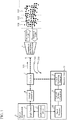
- FIG. 1 is an explanatory diagram illustrating a configuration and the operation of a laser radar device according to the present embodiment.
- the laser radar device illustrated in FIG. 1 includes an optical transmission unit 3 including a light source 1 and a light source driver 2, an optical amplifier 4, a circulator 5, an optical partial reflector 6, a transmission and reception optical system 7, and a detection unit 11 including a light receiving element 8, a current and voltage converter 9, and a signal processor 10.
- the optical transmission unit 3 is a processing unit that transmits a pulse-modulated optical signal having a light intensity set as a Low level component of the pulse.
- the light source 1 of the optical transmission unit 3 is a circuit or an element that emits light
- the light source driver 2 is a device for pulse-modulating an optical signal output from the light source 1.
- the optical amplifier 4 is a circuit that amplifies the optical signal transmitted from the optical transmission unit 3.
- the circulator 5 is a device that transmits the optical signal as transmission light and acquires reflection light from a target in the atmosphere as reception light. There is a space from the transmission output end of the circulator 5, and the transmission and reception optical system 7 is disposed ahead of the space. In this space and the transmission and reception optical system 7, polarization of light is maintained.
- the optical partial reflector 6 is an optical partial reflecting unit provided on a path through which the transmission light is transmitted from the transmission output end of the circulator 5 to the atmosphere.
- the optical partial reflector 6 is provided between the transmission output end of the circulator 5 and the transmission and reception optical system 7, as an optical partial reflecting unit.
- the transmission and reception optical system 7 is an optical system for emitting transmission light from the circulator 5 into the atmosphere and acquiring reflection light from a target.
- the detection unit 11 is a processing unit that performs coherent detection on reception light from the circulator 5 using, as local light, a signal in a Low level section reflected by the optical partial reflector 6.
- the light receiving element 8 of the detection unit 11 is an element performing coherent detection on the local light and the reception light and converting a result of the coherent detection into a current signal.
- the current-voltage converter 9 is a device that converts the current signal from the light receiving element 8 into a voltage signal.
- the signal processor 10 is a device that performs a frequency analysis on the voltage signal from the current-voltage converter 9.
- the transmission paths between the light source 1 and the optical amplifier 4, between the optical amplifier 4 and the circulator 5, between the circulator 5 and the optical partial reflector 6, and between the circulator 5 and the light receiving element 8 are optical transmission paths, it is not necessary to use polarization-maintaining systems such as polarization-maintaining fibers. Specifically, the connection is made by single-mode optical fibers that do not maintain polarization. Meanwhile, the transmission paths between the light source driver 2 and the light source 1, between the light source driver 2 and the signal processor 10, between the light receiving element 8 and the current-voltage converter 9, and between the current-voltage converter 9 and the signal processor 10 are implemented by corresponding electric signal lines.
- distances 101, 102, 103,... each indicate distances of aerosols in the atmosphere from the transmission and reception optical system 7.
- Arrow 100 indicates transmission light output from the circulator 5
- arrow 200 indicates local light input to the circulator 5
- arrow 300 indicates reception light input to the circulator 5.
- the optical amplifier 4 and the transmission and reception optical system 7 are for transmitting light with a large power and receiving light with a large reception aperture, and are used to ensure a signal-to-noise power ratio in reception. However, they are not necessarily essential components for the laser radar device of the first embodiment, because, for example in a case where only a very short distance is measured, the optical transmission power may be small and no large reception aperture is required, and there are cases where a sufficient signal-to-noise power ratio can be ensured even without the optical amplifier 4 and the transmission and reception optical system 7.
- the light source 1, the optical amplifier 4, the circulator 5, and the light receiving element 8 are components having an optical fiber pigtail that is not a polarization-maintaining type, and the optical amplifier 4 is an optical fiber amplifier that is not a polarization-maintaining type.
- Pulse modulation is applied to the light source 1 by a modulation signal from the light source driver 2.
- the extinction ratio (light intensity ratio between a high time period and a low time period in pulse modulation) is adjusted so that a certain level of continuous wave (CW) light is output even in the low time period.
- FIG. 2 A schematic diagram of pulse-modulated light is illustrated in FIG. 2 .
- a low-level signal is obtained by adjusting the extinction ratio and causing a slight leak.
- the light source driver 2 transmits a trigger signal to the signal processor 10 in synchronization with the pulse modulation.
- An optical signal from the light source 1 is amplified by the optical amplifier 4 and sent to the circulator 5.
- the optical signal has the same shape as that in the schematic diagram of FIG. 2 also in the output from the optical amplifier 4.
- the optical signal from the optical amplifier 4 is sent to the optical partial reflector 6 via the circulator 5.
- the optical partial reflector 6 reflects a part of the optical signal sent from the circulator 5 while maintaining the polarization of the optical signal immediately before incidence on the optical partial reflector 6. This reflection light is referred to as partial reflection light in the following description. As will be described later, this partial reflection light is used as local light in coherent detection.
- the optical signal that has passed through the optical partial reflector 6 is transmitted into the atmosphere via the transmission and reception optical system 7, as transmission light.
- Scattered light from the aerosols in the atmosphere is received as reception light via the transmission and reception optical system 7.
- the reception light for the Low signal works as disturbing light; however, it is only required to appropriately adjust the extinction ratio in the pulse modulation so that the level of this disturbing light is sufficiently low with respect to the reception light for transmission of a desired pulse High component.
- the scattered light received by the transmission/reception optical system 7 passes through the optical partial reflector 6, as a reception signal, and is sent to the circulator 5.
- the partial reflection light and the reception light are multiplexed.
- the polarization is maintained during the process from when the optical signal is scattered by the aerosols in the atmosphere via the optical partial reflector 6 and the transmission and reception optical system 7 until the scattered optical signal as reception light is multiplexed with the partial reflection light. Therefore, the partial reflection light and the reception light can be multiplexed in a state where their respective polarizations match.
- the multiplexing of the partial reflection light and the reception light the multiplexing is performed with a time gap by the time for the optical signal to make a round trip in the atmosphere.
- the round-trip time of light is quite short. For example, it takes only 0.1 ms to make a round trip over a distance of 15 km. Meanwhile, fluctuation in the polarization occurs for a period of the order of one second. Therefore, it is conceivable that fluctuation in the polarization during the round-trip time of light is negligible.
- FIG. 3A is a graph illustrating transmission light
- FIG. 3B is a graph illustrating reception light
- a pulse High component 201 illustrated in FIG. 3A has an optical frequency of f0 and does not contribute to reception detection.
- the pulse Low component 202 has an optical frequency of f0 and is used for reception detection.
- Reception light 301 from the distance 101 illustrated in FIG. 3B has an optical frequency of f0 + fd1
- reception light 302 from the distance 102 has an optical frequency of f0 + fd2
- reception light 303 from the distance 103 has an optical frequency of f0 + fd3.
- Symbols fd1, fd2, and fd3 denote Doppler frequency shifts, and the reception light is subjected to a Doppler frequency shift by an amount corresponding to the wind speed of the aerosols travelling by the wind.
- the reception light is multiplexed with the component of the time period of pulse modulation Low out of the partial reflection light.
- the reception light and the partial reflection light are sent to the light receiving element 8 via the circulator 5 in a multiplexed state.
- the reception light and the partial reflection light are coherently detected and converted into a current signal. At this point, it is possible to maintain a high coherent detection efficiency since polarizations of the reception light and the partial reflection light match.
- the current signal from the light receiving element 8 has a Doppler frequency corresponding to a difference in the optical frequency depending on the wind speed.
- This current signal is converted into a voltage signal by the current-voltage converter 9 and sent to the signal processor 10.
- the signal processor 10 can know the optical round-trip time, that is, the origin of the measured distance. Therefore, the distance to the atmospheric range where the reception light has been scattered can be grasped on the time axis of the voltage signal.
- the voltage signal is converted into a digital signal, and is applied with a time gate at a time period corresponding to each distance like in the process described in Non-Patent Literature 1, and each result is subjected to frequency analysis to obtain a Doppler frequency shift, thereby further obtaining the wind speed.
- This makes it possible to obtain the distribution of wind speed in a distance direction by one time of pulse transmission.
- a means of frequency analysis it suffices to use fast Fourier transform or the like.
- the laser radar device of the first embodiment it is possible to maintain a high coherent detection efficiency in optical reception without making an optical transmission path a polarization-maintaining system. Moreover, a pulse modulation function is further included, and it is possible to simultaneously obtain the distribution of wind in the distance direction.
- optical components that does not maintain the polarization.
- optical components include a single mode optical fiber that does not maintain the polarization, an optical fiber amplifier using the optical fiber, an optical circulator using the optical fiber, and a semiconductor laser diode including a pigtail of the optical fiber.
- costly polarization-maintaining components are required, in order to maintain a high coherent detection efficiency. These costly optical components are unnecessary, and thus both lower costs and a high coherent detection efficiency can be achieved.
- an optical splitter which is necessary for separating transmission light and local light
- an optical multiplexer which is necessary for multiplexing the local light and scattered light in the related art are unnecessary, which also exerts the effect of reducing the costs.
- optical partial reflector 6 is disposed subsequent to the transmission output end of the circulator 5 in the above example; however, in a case where the circulator 5 is a component including an optical fiber pigtail, the optical partial reflector 6 can also be implemented by applying partial reflection coating to the transmission output end. Moreover, a certain amount of partial reflection always occurs at the transmission output end of the circulator 5 due to the difference in the refractive index between the optical fiber and the air, and thus this can be used as a partial reflection function. Therefore, although the function of optical partial reflection itself is necessary in the laser radar device of the present invention, a configuration other than the optical partial reflector 6 may be used as a means for implementing the function.
- the partial reflection function of the optical partial reflector 6 is disposed on the output side of the transmission and reception optical system 7, that is, on the atmosphere side, it is unnecessary for the space between the circulator 5 and the transmission and reception optical system 7 as well as the transmission and reception optical system 7 to maintain the polarization.
- the partial reflection function needs to be on the output side of the circulator 5, but as long as a change in polarization is small in the process in which transmission light is transmitted therefrom to the atmosphere, the function works effectively regardless of its location.
- setting a high reflectance in the optical partial reflector 6 corresponds to setting a high level of local light in the coherent detection, and thus this makes it easier to bring the reception state closer to the shot noise limit which is the ideal detection state in coherent detection.
- pulse light having a high peak is also reflected at a high reflectance in this case, and thus the light receiving element 8 may be damaged when the reflected pulse light is input to the light receiving element 8. Therefore, there is a case where it is necessary to set a low reflectance in the optical partial reflector 6. In such a case, the level of partial reflection light also decreases, and it is difficult to approach the shot noise limit.
- This example illustrates a configuration in which a negative feedback resistor 9b is connected to an operational amplifier 9a. With this configuration, it is possible to implement a state close to the shot noise limit even in a case where the level of partial reflection light decreases.
- this laser radar device is mounted on a wind turbine or disposed in the vicinity thereof, and is used for the purpose of measuring the wind in front of the wind turbine. More specifically, in an application case such as wind turbine control by front wind measurement or evaluation of the wind turbine power generation, operation is made with the wind turbine facing in a head wind direction, and thus the positive and negative of the wind speed are known and not required to be distinguished.
- the light source 1 is applied with pulse modulation.
- a specific example of this method is illustrated in FIG. 5 .
- the configuration illustrated in FIG. 5A is an example of direct modulation on a driving current for the light source 1 which is a semiconductor laser diode.
- output from a CW light source such as a semiconductor laser diode 1a is modulated by a pulse modulator 1b.
- the pulse modulator 1b for example, an optical semiconductor amplifier, a Mach-Zehnder type optical modulator, or an acousto-optic (AO) modulator are conceivable.
- pulse modulation involves a frequency shift. Therefore, if this frequency shift amount is appropriately adjusted, this is the intermediate frequency in the coherent detection, thereby allowing the positive and negative of the Doppler frequency shift, that is, the positive and negative of the wind speed, to be distinguished, and enabling further enhancement in the functionality.
- the laser radar device has been described as a coherent laser radar that measures the wind; however, the measurement target is not limited to the wind, and the laser radar device is applicable to all laser radars that adopt coherent detection by a pulse method, such as a laser range finder that measures, for example, round-trip time of pulse light to a hard target.
- a pulse method such as a laser range finder that measures, for example, round-trip time of pulse light to a hard target.
- the noise level can be stabilized by making the conversion gain in the current-voltage converter 9 variable and controlling this gain depending on the reception state.
- a conceivable approach is to prepare multiple feedback resistors of a negative feedback transimpedance gain and to switch among the feedback resistors.
- the configuration illustrated in the figure is an example in which three negative feedback resistors 9b-1, 9b-2, and 9b-3 are switched using switches 9c-1, 9c-2, and 9c-3 provided corresponding to the negative feedback resistors 9b-1, 9b-2, and 9b-3, respectively.
- this configuration includes the function of transmitting a control signal to the switches 9c-1, 9c-2, and 9c-3 from the signal processor 10 to the current-voltage converter 9.
- the partial reflection light can be made constant by newly providing the function of adjusting a modulation signal from the light source driver 2.
- the function of transmitting a control signal from the signal processor 10 to the light source driver 2 is provided.
- the partial reflection light can be made constant by newly providing the function of adjusting the reflectance of the optical partial reflector 6.
- the function of transmitting a control signal from the signal processor 10 to the optical partial reflector 6 is provided.
- a means for adjusting the reflectance a means such as changing the inclination of the optical partial reflector is conceivable.
- the first embodiment has been described on the assumption that all optical components are non-polarization-maintaining components; however, even when some or all of the components are polarization-maintaining components, it is goes without saying that this poses no problem to the functionality. If non-polarization-maintaining components can be used in some components, this alone can reduce costs. Moreover, even when polarization-maintaining components are used for all the components, there is an effect of reducing costs since an optical splitter and a multiplexer are unnecessary which used to be necessary in a conventional laser radar using a pulse method and coherent detection.
- FIG. 7 an example in which semiconductor laser diodes 1a-1, 1a-2, and 1a-3 each of which outputs a different wavelength, and a wavelength-combined optical multiplexer 1c are included, is illustrated.
- the optical amplifier 4 is an optical fiber amplifier and the pulse peak in optical output is limited due to a nonlinear phenomenon in the optical fiber, it is possible to differentiate the multiple wavelengths so that the nonlinear phenomenon can be avoided, and to avoid the pulse peak from being limited.
- the laser radar device of the first embodiment includes: the optical transmission unit for transmitting a pulse-modulated optical signal having a light intensity set as a low-level component of a pulse; the circulator for transmitting the optical signal as transmission light and acquiring reflection light from a target in the atmosphere as reception light; the optical partial reflecting unit for reflecting the optical signal, the optical partial reflecting unit being provided on a path through which the transmission light is transmitted from the circulator to the atmosphere; and the detection unit for performing coherent detection on the reception light using, as local light, a signal in a Low level section of the optical signal reflected by the optical partial reflecting unit. Therefore, the configuration is simplified, thereby reducing costs.
- the detection unit includes: the light receiving element for performing coherent detection on the local light and the reception light and converting a result of the coherent detection to a current signal; the current-voltage converter for converting the current signal from the light receiving element into a voltage signal; and the signal processor for performing frequency analysis on the voltage signal from the current-voltage converter. Therefore, a configuration as a coherent detection unit can be easily implemented.
- the current-voltage converter is a negative feedback transimpedance amplifier, and thus a state close to the shot noise limit can be implemented even in a case where when the level of partial reflection light decreases.
- the laser radar device of the first embodiment is installed at a position where the wind direction is a head wind direction, the wind speed can be measured even in a case where there is no frequency change in the High and Low time periods in pulse modulation.
- the wind speed can be measured even in a case where there is no frequency change in the High and Low time periods in pulse modulation.
- the optical transmission unit employs a semiconductor laser diode as the light source for emitting light, and applies pulse modulation on a driving current for the semiconductor laser diode, and thus an optical signal having a light intensity set as the Low level component of the pulse can be easily transmitted.
- the optical transmission unit includes the light source for outputting a continuous wave and a pulse modulator, and a single or multiple semiconductor amplifiers or a single or multiple acousto-optic modulators are used as the pulse modulator, and thus it is possible to distinguish between the positive and negative of the wind speed by appropriately adjusting the frequency shift amount, thereby enabling further enhancement in the functionality.
- the conversion gain of the current-voltage converter is variable, and the conversion gain is controlled by the signal processor, and thus the gain can be controlled depending on the reception state of reception light, thereby enabling stabilization of the noise level.
- the extinction ratio which is a ratio between the High level and the Low level of the pulse of an optical signal output from the optical transmission unit is controlled by the signal processor, and thus partial reflection light can be made constant.
- the reflectance in the optical partial reflecting unit is controlled by the signal processor, and thus partial reflection light can be made constant.
- the optical transmission unit includes multiple light sources, multiplexes multiple optical signals from these light sources, and outputs the multiplexed optical signals as an optical signal, and thus limitations on the pulse peak can be avoided by differentiating multiple wavelengths.
- a laser radar device relates to a configuration using coherent detection, and is suitable for use in a laser radar device for measuring wind.
- 1 light source, 1a, 1a-1, 1a-2, 1a-3: semiconductor laser diode, 1b: pulse modulator, 1c: wavelength-combined optical multiplexer, 2: light source driver, 3: optical transmission unit, 4: optical amplifier, 5: circulator, 6: optical partial reflector, 7: transmission and reception optical system, 8: light receiving element, 9: current-voltage converter, 9a: operational amplifier, 9b, 9b-1, 9b-2, 9b-3: negative feedback resistor, 9c-1, 9c-2, 9c-3: switch, 10: signal processor, 11: detection unit
Landscapes
- Engineering & Computer Science (AREA)
- Physics & Mathematics (AREA)
- Computer Networks & Wireless Communication (AREA)
- General Physics & Mathematics (AREA)
- Radar, Positioning & Navigation (AREA)
- Remote Sensing (AREA)
- Electromagnetism (AREA)
- Environmental & Geological Engineering (AREA)
- Life Sciences & Earth Sciences (AREA)
- Atmospheric Sciences (AREA)
- Biodiversity & Conservation Biology (AREA)
- Ecology (AREA)
- Environmental Sciences (AREA)
- Optical Radar Systems And Details Thereof (AREA)
Abstract
Description
- The present invention relates to a laser radar device using coherent detection.
- As laser radar devices for measuring wind, systems using coherent detection that enables Doppler frequency measurement and high-sensitivity reception are mainly used. In such a laser radar device, a pulse method is necessary for simultaneous measurement of the distribution in a distance direction, and this method is conventionally used (for example, see Non-Patent Literature 1).
- Conventional laser radar devices divide continuous wave (CW) light from a light source into transmission light and local light, pulse-modulate the transmission light, amplify by an optical amplifier, transmit and receive the pulse light to and from aerosols in the atmosphere via an optical circulator and a transmission and reception optical system, multiplex reception light and the local light by an optical multiplexer, and perform coherent detection by a light receiving element and a current-voltage converter. Provided is the function of obtaining a wind speed that corresponds to a Doppler frequency shift for each distance by performing frequency analysis on the detected signal by a signal processor.
- Non-Patent Literature 1: T. Ando et al., "All-fiber coherent Doppler technologies at Mitsubishi Electric Corporation," IOP Conference Series: Earth and Environmental Science, .
- However, conventional laser radar devices that obtain a wind speed distribution in a distance direction, especially those using the coherent method and the pulse method described above, have the following disadvantages. That is, it is necessary in laser radar devices that the polarization of scattered light from aerosols in the atmosphere and the polarization of local light match when the scattered light and the local light are multiplexed and subjected to coherent detection, in order to maintain a high detection efficiency. Therefore, in conventional laser radar devices, it is necessary to use costly components for maintaining the polarization in optical components or an optical transmission system. Another factor for an increase in costs is the need of a splitter for splitting output of a light source into transmission light and local light and a multiplexer for multiplexing the local light and reception light.
- The present invention has been made to solve the above-described disadvantages, and an object of the invention is to provide a laser radar device capable of simplifying the configuration and reducing costs.
- A laser radar device according to the present invention includes: an optical transmission unit for transmitting a pulse-modulated optical signal having a light intensity set as a low-level component of a pulse; a circulator for transmitting the optical signal as transmission light and acquiring reflection light from a target in an atmosphere as reception light; an optical partial reflecting unit for reflecting the optical signal, the optical partial reflecting unit being provided on a path through which the transmission light is transmitted from the circulator to the atmosphere; and a detection unit for performing coherent detection on the reception light using, as local light, a signal in a Low level section of the optical signal reflected by the optical partial reflecting unit.
- According to the laser radar device of the present invention, a pulse-modulated optical signal is reflected by the optical partial reflecting unit, and reflection light in the Low level section of the optical signal is used as local light. As a result, the configuration can be simplified and costs can be reduced.
-
-
FIG. 1 is an explanatory diagram illustrating a configuration and the operation of a laser radar device according to a first embodiment of the present invention. -
FIG. 2 is an explanatory diagram of a pulse-modulated optical signal of the laser radar device according to the first embodiment of the present invention. -
FIGS. 3A and 3B are explanatory graphs illustrating a timing shift in a time direction between partial reflection light and reception light of the laser radar device according to the first embodiment of the present invention. -
FIG. 4 is a configuration diagram illustrating an example of a current-voltage converter of the laser radar device according to the first embodiment of the present invention. -
FIGS. 5A and 5B are configuration diagrams each illustrating an example of a light source of the laser radar device according to the first embodiment of the present invention. -
FIG. 6 is a configuration diagram illustrating another example of the current-voltage converter of the laser radar device according to the first embodiment of the present invention. -
FIG. 7 is a configuration diagram illustrating another example of the light source of the laser radar device according to the first embodiment of the present invention. - To describe the present invention further in detail, embodiments for carrying out the present invention will be described below by referring to the accompanying drawings.
-
FIG. 1 is an explanatory diagram illustrating a configuration and the operation of a laser radar device according to the present embodiment. - The laser radar device illustrated in
FIG. 1 includes anoptical transmission unit 3 including alight source 1 and alight source driver 2, anoptical amplifier 4, a circulator 5, an optical partial reflector 6, a transmission and reception optical system 7, and adetection unit 11 including alight receiving element 8, a current andvoltage converter 9, and asignal processor 10. Theoptical transmission unit 3 is a processing unit that transmits a pulse-modulated optical signal having a light intensity set as a Low level component of the pulse. Thelight source 1 of theoptical transmission unit 3 is a circuit or an element that emits light, and thelight source driver 2 is a device for pulse-modulating an optical signal output from thelight source 1. Theoptical amplifier 4 is a circuit that amplifies the optical signal transmitted from theoptical transmission unit 3. The circulator 5 is a device that transmits the optical signal as transmission light and acquires reflection light from a target in the atmosphere as reception light. There is a space from the transmission output end of the circulator 5, and the transmission and reception optical system 7 is disposed ahead of the space. In this space and the transmission and reception optical system 7, polarization of light is maintained. - The optical partial reflector 6 is an optical partial reflecting unit provided on a path through which the transmission light is transmitted from the transmission output end of the circulator 5 to the atmosphere. In the illustrated example, the optical partial reflector 6 is provided between the transmission output end of the circulator 5 and the transmission and reception optical system 7, as an optical partial reflecting unit. The transmission and reception optical system 7 is an optical system for emitting transmission light from the circulator 5 into the atmosphere and acquiring reflection light from a target. The
detection unit 11 is a processing unit that performs coherent detection on reception light from the circulator 5 using, as local light, a signal in a Low level section reflected by the optical partial reflector 6. The light receivingelement 8 of thedetection unit 11 is an element performing coherent detection on the local light and the reception light and converting a result of the coherent detection into a current signal. The current-voltage converter 9 is a device that converts the current signal from thelight receiving element 8 into a voltage signal. Thesignal processor 10 is a device that performs a frequency analysis on the voltage signal from the current-voltage converter 9. - In such a configuration, as illustrated by broken lines in the figure, although the transmission paths between the
light source 1 and theoptical amplifier 4, between theoptical amplifier 4 and the circulator 5, between the circulator 5 and the optical partial reflector 6, and between the circulator 5 and thelight receiving element 8 are optical transmission paths, it is not necessary to use polarization-maintaining systems such as polarization-maintaining fibers. Specifically, the connection is made by single-mode optical fibers that do not maintain polarization. Meanwhile, the transmission paths between thelight source driver 2 and thelight source 1, between thelight source driver 2 and thesignal processor 10, between the light receivingelement 8 and the current-voltage converter 9, and between the current-voltage converter 9 and thesignal processor 10 are implemented by corresponding electric signal lines. These signal lines are illustrated by solid lines. Furthermore,distances Arrow 100 indicates transmission light output from the circulator 5,arrow 200 indicates local light input to the circulator 5, andarrow 300 indicates reception light input to the circulator 5. - The
optical amplifier 4 and the transmission and reception optical system 7 are for transmitting light with a large power and receiving light with a large reception aperture, and are used to ensure a signal-to-noise power ratio in reception. However, they are not necessarily essential components for the laser radar device of the first embodiment, because, for example in a case where only a very short distance is measured, the optical transmission power may be small and no large reception aperture is required, and there are cases where a sufficient signal-to-noise power ratio can be ensured even without theoptical amplifier 4 and the transmission and reception optical system 7. - In
FIG. 1 , thelight source 1, theoptical amplifier 4, the circulator 5, and thelight receiving element 8 are components having an optical fiber pigtail that is not a polarization-maintaining type, and theoptical amplifier 4 is an optical fiber amplifier that is not a polarization-maintaining type. - Next, the operation of the laser radar device according to the first embodiment will be described.
- Pulse modulation is applied to the
light source 1 by a modulation signal from thelight source driver 2. At this point, the extinction ratio (light intensity ratio between a high time period and a low time period in pulse modulation) is adjusted so that a certain level of continuous wave (CW) light is output even in the low time period. A schematic diagram of pulse-modulated light is illustrated inFIG. 2 . As illustrated inFIG. 2 , a low-level signal is obtained by adjusting the extinction ratio and causing a slight leak. Furthermore, thelight source driver 2 transmits a trigger signal to thesignal processor 10 in synchronization with the pulse modulation. - An optical signal from the
light source 1 is amplified by theoptical amplifier 4 and sent to the circulator 5. The optical signal has the same shape as that in the schematic diagram ofFIG. 2 also in the output from theoptical amplifier 4. The optical signal from theoptical amplifier 4 is sent to the optical partial reflector 6 via the circulator 5. The optical partial reflector 6 reflects a part of the optical signal sent from the circulator 5 while maintaining the polarization of the optical signal immediately before incidence on the optical partial reflector 6. This reflection light is referred to as partial reflection light in the following description. As will be described later, this partial reflection light is used as local light in coherent detection. - The optical signal that has passed through the optical partial reflector 6 is transmitted into the atmosphere via the transmission and reception optical system 7, as transmission light. Scattered light from the aerosols in the atmosphere is received as reception light via the transmission and reception optical system 7. At this point, not only the signal at pulse High but also the signal at Low are transmitted and received into and from the atmosphere, but only the optical signal at pulse High is used. The reception light for the Low signal works as disturbing light; however, it is only required to appropriately adjust the extinction ratio in the pulse modulation so that the level of this disturbing light is sufficiently low with respect to the reception light for transmission of a desired pulse High component.
- The scattered light received by the transmission/reception optical system 7 passes through the optical partial reflector 6, as a reception signal, and is sent to the circulator 5. At this point, the partial reflection light and the reception light are multiplexed. At this point, the polarization is maintained during the process from when the optical signal is scattered by the aerosols in the atmosphere via the optical partial reflector 6 and the transmission and reception optical system 7 until the scattered optical signal as reception light is multiplexed with the partial reflection light. Therefore, the partial reflection light and the reception light can be multiplexed in a state where their respective polarizations match. As for the multiplexing of the partial reflection light and the reception light, the multiplexing is performed with a time gap by the time for the optical signal to make a round trip in the atmosphere. Therefore, if the polarization state in the laser radar device changes during this round-trip time, the degree of coincidence of polarizations between the partial reflection light and the reception light decreases in the multiplexing, thereby deteriorating the detection efficiency. However, the round-trip time of light is quite short. For example, it takes only 0.1 ms to make a round trip over a distance of 15 km. Meanwhile, fluctuation in the polarization occurs for a period of the order of one second. Therefore, it is conceivable that fluctuation in the polarization during the round-trip time of light is negligible.
- A timing shift between partial reflection light and reception light in the time direction is illustrated in
FIG. 3. FIG. 3A is a graph illustrating transmission light, andFIG. 3B is a graph illustrating reception light. A pulseHigh component 201 illustrated inFIG. 3A has an optical frequency of f0 and does not contribute to reception detection. On the other hand, the pulseLow component 202 has an optical frequency of f0 and is used for reception detection. Reception light 301 from thedistance 101 illustrated inFIG. 3B has an optical frequency of f0 + fd1, reception light 302 from thedistance 102 has an optical frequency of f0 + fd2, and reception light 303 from thedistance 103 has an optical frequency of f0 + fd3. Symbols fd1, fd2, and fd3 denote Doppler frequency shifts, and the reception light is subjected to a Doppler frequency shift by an amount corresponding to the wind speed of the aerosols travelling by the wind. The reception light is multiplexed with the component of the time period of pulse modulation Low out of the partial reflection light. - The reception light and the partial reflection light are sent to the
light receiving element 8 via the circulator 5 in a multiplexed state. In thelight receiving element 8, the reception light and the partial reflection light are coherently detected and converted into a current signal. At this point, it is possible to maintain a high coherent detection efficiency since polarizations of the reception light and the partial reflection light match. - The current signal from the
light receiving element 8 has a Doppler frequency corresponding to a difference in the optical frequency depending on the wind speed. This current signal is converted into a voltage signal by the current-voltage converter 9 and sent to thesignal processor 10. By receiving a trigger signal from thelight source driver 2, thesignal processor 10 can know the optical round-trip time, that is, the origin of the measured distance. Therefore, the distance to the atmospheric range where the reception light has been scattered can be grasped on the time axis of the voltage signal. In thesignal processor 10, the voltage signal is converted into a digital signal, and is applied with a time gate at a time period corresponding to each distance like in the process described inNon-Patent Literature 1, and each result is subjected to frequency analysis to obtain a Doppler frequency shift, thereby further obtaining the wind speed. This makes it possible to obtain the distribution of wind speed in a distance direction by one time of pulse transmission. As for a means of frequency analysis, it suffices to use fast Fourier transform or the like. In a case where reception cannot be performed with a sufficient signal-to-noise ratio in one time of pulse transmission, it is only required to perform the above-mentioned pulse transmission and reception operation for multiple times so that a sufficient signal-to-noise ratio can be obtained by signal processing such as incoherent integration. - As described above, in the laser radar device of the first embodiment, it is possible to maintain a high coherent detection efficiency in optical reception without making an optical transmission path a polarization-maintaining system. Moreover, a pulse modulation function is further included, and it is possible to simultaneously obtain the distribution of wind in the distance direction.
- Furthermore, since it is not necessary to use a polarization-maintaining system in the optical transmission paths, it is possible to use optical components that does not maintain the polarization. Examples of such optical components include a single mode optical fiber that does not maintain the polarization, an optical fiber amplifier using the optical fiber, an optical circulator using the optical fiber, and a semiconductor laser diode including a pigtail of the optical fiber. In the related art, as for these optical components, costly polarization-maintaining components are required, in order to maintain a high coherent detection efficiency. These costly optical components are unnecessary, and thus both lower costs and a high coherent detection efficiency can be achieved.
- Furthermore, an optical splitter which is necessary for separating transmission light and local light, and an optical multiplexer which is necessary for multiplexing the local light and scattered light in the related art are unnecessary, which also exerts the effect of reducing the costs.
- Note that although the optical partial reflector 6 is disposed subsequent to the transmission output end of the circulator 5 in the above example; however, in a case where the circulator 5 is a component including an optical fiber pigtail, the optical partial reflector 6 can also be implemented by applying partial reflection coating to the transmission output end. Moreover, a certain amount of partial reflection always occurs at the transmission output end of the circulator 5 due to the difference in the refractive index between the optical fiber and the air, and thus this can be used as a partial reflection function. Therefore, although the function of optical partial reflection itself is necessary in the laser radar device of the present invention, a configuration other than the optical partial reflector 6 may be used as a means for implementing the function.
- Furthermore, if the partial reflection function of the optical partial reflector 6 is disposed on the output side of the transmission and reception optical system 7, that is, on the atmosphere side, it is unnecessary for the space between the circulator 5 and the transmission and reception optical system 7 as well as the transmission and reception optical system 7 to maintain the polarization. In other words, the partial reflection function needs to be on the output side of the circulator 5, but as long as a change in polarization is small in the process in which transmission light is transmitted therefrom to the atmosphere, the function works effectively regardless of its location.
- In the first embodiment of the present invention, setting a high reflectance in the optical partial reflector 6 corresponds to setting a high level of local light in the coherent detection, and thus this makes it easier to bring the reception state closer to the shot noise limit which is the ideal detection state in coherent detection. However, pulse light having a high peak is also reflected at a high reflectance in this case, and thus the
light receiving element 8 may be damaged when the reflected pulse light is input to thelight receiving element 8. Therefore, there is a case where it is necessary to set a low reflectance in the optical partial reflector 6. In such a case, the level of partial reflection light also decreases, and it is difficult to approach the shot noise limit. In this case, a transimpedance amplifier of a negative feedback type illustrated inFIG. 4 is used as the current-voltage converter 9. This example illustrates a configuration in which anegative feedback resistor 9b is connected to anoperational amplifier 9a. With this configuration, it is possible to implement a state close to the shot noise limit even in a case where the level of partial reflection light decreases. - Note that coherent detection is homodyne in the first embodiment if there is no frequency change in the High and Low time periods in the pulse modulation, and thus the positive and negative of the Doppler frequency, that is, the positive and negative of the wind speed cannot be distinguished. However, for example, this laser radar device is mounted on a wind turbine or disposed in the vicinity thereof, and is used for the purpose of measuring the wind in front of the wind turbine. More specifically, in an application case such as wind turbine control by front wind measurement or evaluation of the wind turbine power generation, operation is made with the wind turbine facing in a head wind direction, and thus the positive and negative of the wind speed are known and not required to be distinguished. In other words, there is no problem since the positive and negative of the wind speed are known in advance in a case where the laser radar device is installed in a wind turbine. Note that "in a case where the laser radar device is installed in a wind turbine" includes installment in the vicinity of a wind turbine.
- In the first embodiment, the
light source 1 is applied with pulse modulation. A specific example of this method is illustrated inFIG. 5 . The configuration illustrated inFIG. 5A is an example of direct modulation on a driving current for thelight source 1 which is a semiconductor laser diode. In the configuration illustrated inFIG. 5B , output from a CW light source such as a semiconductor laser diode 1a is modulated by a pulse modulator 1b. As for the pulse modulator 1b, for example, an optical semiconductor amplifier, a Mach-Zehnder type optical modulator, or an acousto-optic (AO) modulator are conceivable. Of these, in particular, in direct modulation to the semiconductor laser diode 1a and in modulation using an optical semiconductor amplifier and an acousto-optic modulator, pulse modulation involves a frequency shift. Therefore, if this frequency shift amount is appropriately adjusted, this is the intermediate frequency in the coherent detection, thereby allowing the positive and negative of the Doppler frequency shift, that is, the positive and negative of the wind speed, to be distinguished, and enabling further enhancement in the functionality. - Furthermore, in the first embodiment, the laser radar device has been described as a coherent laser radar that measures the wind; however, the measurement target is not limited to the wind, and the laser radar device is applicable to all laser radars that adopt coherent detection by a pulse method, such as a laser range finder that measures, for example, round-trip time of pulse light to a hard target.
- In the first embodiment, there may be a case where the level of partial reflection light is not stable, so that fluctuation in the noise level or the like in the signal processing interferes with the Doppler frequency shift and the wind speed detection processing. However, in this case, the noise level can be stabilized by making the conversion gain in the current-
voltage converter 9 variable and controlling this gain depending on the reception state. Specifically, as illustrated inFIG. 6 , a conceivable approach is to prepare multiple feedback resistors of a negative feedback transimpedance gain and to switch among the feedback resistors. The configuration illustrated in the figure is an example in which threenegative feedback resistors 9b-1, 9b-2, and 9b-3 are switched usingswitches 9c-1, 9c-2, and 9c-3 provided corresponding to thenegative feedback resistors 9b-1, 9b-2, and 9b-3, respectively. Note that, although not illustrated, this configuration includes the function of transmitting a control signal to theswitches 9c-1, 9c-2, and 9c-3 from thesignal processor 10 to the current-voltage converter 9. - Furthermore, in a case where the partial reflection light is unstable as mentioned above, the partial reflection light can be made constant by newly providing the function of adjusting a modulation signal from the
light source driver 2. In this case, although not illustrated, the function of transmitting a control signal from thesignal processor 10 to thelight source driver 2 is provided. - In addition, in a case where the partial reflection light is unstable as mentioned above, the partial reflection light can be made constant by newly providing the function of adjusting the reflectance of the optical partial reflector 6. In this case, although not illustrated, the function of transmitting a control signal from the
signal processor 10 to the optical partial reflector 6 is provided. As for a means for adjusting the reflectance, a means such as changing the inclination of the optical partial reflector is conceivable. - The first embodiment has been described on the assumption that all optical components are non-polarization-maintaining components; however, even when some or all of the components are polarization-maintaining components, it is goes without saying that this poses no problem to the functionality. If non-polarization-maintaining components can be used in some components, this alone can reduce costs. Moreover, even when polarization-maintaining components are used for all the components, there is an effect of reducing costs since an optical splitter and a multiplexer are unnecessary which used to be necessary in a conventional laser radar using a pulse method and coherent detection.
- In the first embodiment, the case of a single
light source 1 has been described; however, if multiple light sources that output different wavelengths are provided as illustrated inFIG. 7 and these pieces of output are multiplexed, another effect is newly obtained. InFIG. 7 , an example in which semiconductor laser diodes 1a-1, 1a-2, and 1a-3 each of which outputs a different wavelength, and a wavelength-combined optical multiplexer 1c are included, is illustrated. With such a configuration, especially, for example, in a case where theoptical amplifier 4 is an optical fiber amplifier and the pulse peak in optical output is limited due to a nonlinear phenomenon in the optical fiber, it is possible to differentiate the multiple wavelengths so that the nonlinear phenomenon can be avoided, and to avoid the pulse peak from being limited. - As described above, the laser radar device of the first embodiment includes: the optical transmission unit for transmitting a pulse-modulated optical signal having a light intensity set as a low-level component of a pulse; the circulator for transmitting the optical signal as transmission light and acquiring reflection light from a target in the atmosphere as reception light; the optical partial reflecting unit for reflecting the optical signal, the optical partial reflecting unit being provided on a path through which the transmission light is transmitted from the circulator to the atmosphere; and the detection unit for performing coherent detection on the reception light using, as local light, a signal in a Low level section of the optical signal reflected by the optical partial reflecting unit. Therefore, the configuration is simplified, thereby reducing costs.
- Further according to the laser radar device of the first embodiment, the detection unit includes: the light receiving element for performing coherent detection on the local light and the reception light and converting a result of the coherent detection to a current signal; the current-voltage converter for converting the current signal from the light receiving element into a voltage signal; and the signal processor for performing frequency analysis on the voltage signal from the current-voltage converter. Therefore, a configuration as a coherent detection unit can be easily implemented.
- Moreover, according to the laser radar device of the first embodiment, the current-voltage converter is a negative feedback transimpedance amplifier, and thus a state close to the shot noise limit can be implemented even in a case where when the level of partial reflection light decreases.
- Furthermore, since the laser radar device of the first embodiment is installed at a position where the wind direction is a head wind direction, the wind speed can be measured even in a case where there is no frequency change in the High and Low time periods in pulse modulation.
- Furthermore, according to the laser radar device of the first embodiment, since a position where the wind direction is a head wind direction is a position of a wind turbine, the wind speed can be measured even in a case where there is no frequency change in the High and Low time periods in pulse modulation.
- Also according to the laser radar device of the first embodiment, the optical transmission unit employs a semiconductor laser diode as the light source for emitting light, and applies pulse modulation on a driving current for the semiconductor laser diode, and thus an optical signal having a light intensity set as the Low level component of the pulse can be easily transmitted.
- Further according to the laser radar device of the first embodiment, the optical transmission unit includes the light source for outputting a continuous wave and a pulse modulator, and a single or multiple semiconductor amplifiers or a single or multiple acousto-optic modulators are used as the pulse modulator, and thus it is possible to distinguish between the positive and negative of the wind speed by appropriately adjusting the frequency shift amount, thereby enabling further enhancement in the functionality.
- According to the laser radar device of the first embodiment, the conversion gain of the current-voltage converter is variable, and the conversion gain is controlled by the signal processor, and thus the gain can be controlled depending on the reception state of reception light, thereby enabling stabilization of the noise level.
- In addition, according to the laser radar device of the first embodiment, the extinction ratio which is a ratio between the High level and the Low level of the pulse of an optical signal output from the optical transmission unit is controlled by the signal processor, and thus partial reflection light can be made constant.
- Moreover, according to the laser radar device of the first embodiment, the reflectance in the optical partial reflecting unit is controlled by the signal processor, and thus partial reflection light can be made constant.
- Further according to the laser radar device of the first embodiment, the optical transmission unit includes multiple light sources, multiplexes multiple optical signals from these light sources, and outputs the multiplexed optical signals as an optical signal, and thus limitations on the pulse peak can be avoided by differentiating multiple wavelengths.
- Note that the present invention may include modifications of any component of the embodiment, or omission of any component of the embodiment within the scope of the present invention.
- As described above, a laser radar device according to the present invention relates to a configuration using coherent detection, and is suitable for use in a laser radar device for measuring wind.
- 1: light source, 1a, 1a-1, 1a-2, 1a-3: semiconductor laser diode, 1b: pulse modulator, 1c: wavelength-combined optical multiplexer, 2: light source driver, 3: optical transmission unit, 4: optical amplifier, 5: circulator, 6: optical partial reflector, 7: transmission and reception optical system, 8: light receiving element, 9: current-voltage converter, 9a: operational amplifier, 9b, 9b-1, 9b-2, 9b-3: negative feedback resistor, 9c-1, 9c-2, 9c-3: switch, 10: signal processor, 11: detection unit
Claims (11)
- A laser radar device comprising:an optical transmission unit for transmitting a pulse-modulated optical signal having a light intensity set as a low-level component of a pulse;a circulator for transmitting the optical signal as transmission light and acquiring reflection light from a target in an atmosphere as reception light;an optical partial reflecting unit for reflecting the optical signal, the optical partial reflecting unit being provided on a path through which the transmission light is transmitted from the circulator to the atmosphere; anda detection unit for performing coherent detection on the reception light using, as local light, a signal in a Low level section of the optical signal reflected by the optical partial reflecting unit.
- The laser radar device according to claim 1,
wherein the detection unit comprises:a light receiving element for performing coherent detection on the local light and the reception light and converting a result of the coherent detection to a current signal;a current-voltage converter for converting the current signal from the light receiving element into a voltage signal; anda signal processor for performing frequency analysis on the voltage signal from the current-voltage converter. - The laser radar device according to claim 2, wherein the current-voltage converter is a transimpedance amplifier of a negative feedback type.
- The laser radar device according to claim 1, wherein the laser radar device is installed at a position where a wind direction is a head wind direction.
- The laser radar device according to claim 4, wherein the position where the wind direction is the head wind direction is a position of a wind turbine.
- The laser radar device according to claim 1, wherein the optical transmission unit uses a semiconductor laser diode as a light source for emitting light and applies pulse modulation to a driving current for the semiconductor laser diode.
- The laser radar device according to claim 1, wherein the optical transmission unit comprises a light source for outputting a continuous wave and a pulse modulator, and a single or multiple semiconductor amplifiers or a single or multiple acousto-optic modulators are used as the pulse modulator.
- The laser radar device according to claim 2, wherein a conversion gain of the current-voltage converter is variable, and the conversion gain is controlled by the signal processor.
- The laser radar device according to claim 2, wherein an extinction ratio which is a ratio between a high level and a low level of the pulse of the optical signal output from the optical transmission unit is controlled by the signal processor.
- The laser radar device according to claim 2, wherein a reflectance in the optical partial reflecting unit is controlled by the signal processor.
- The laser radar device according to claim 1, wherein the optical transmission unit comprises multiple light sources, multiplexes multiple optical signals from the light sources, and outputs the multiplexed optical signals as the optical signal.
Applications Claiming Priority (1)
| Application Number | Priority Date | Filing Date | Title |
|---|---|---|---|
| PCT/JP2018/013302 WO2019186914A1 (en) | 2018-03-29 | 2018-03-29 | Laser radar device |
Publications (3)
| Publication Number | Publication Date |
|---|---|
| EP3754364A1 true EP3754364A1 (en) | 2020-12-23 |
| EP3754364A4 EP3754364A4 (en) | 2021-03-10 |
| EP3754364B1 EP3754364B1 (en) | 2023-01-11 |
Family
ID=68059616
Family Applications (1)
| Application Number | Title | Priority Date | Filing Date |
|---|---|---|---|
| EP18911713.8A Active EP3754364B1 (en) | 2018-03-29 | 2018-03-29 | Laser radar device |
Country Status (5)
| Country | Link |
|---|---|
| US (1) | US11933903B2 (en) |
| EP (1) | EP3754364B1 (en) |
| JP (1) | JP6797327B2 (en) |
| CN (1) | CN111886513B (en) |
| WO (1) | WO2019186914A1 (en) |
Cited By (1)
| Publication number | Priority date | Publication date | Assignee | Title |
|---|---|---|---|---|
| EP4607207A1 (en) * | 2024-02-20 | 2025-08-27 | Honeywell International Inc. | Modular air-data system |
Families Citing this family (4)
| Publication number | Priority date | Publication date | Assignee | Title |
|---|---|---|---|---|
| CN111505766B (en) * | 2020-05-08 | 2021-08-06 | 电子科技大学 | An optical full-duplex transceiver based on silicon-based integrated magneto-optical circulator |
| CN113176581B (en) * | 2021-03-15 | 2021-12-31 | 北京华信科创科技有限公司 | Doppler pulse laser wind measuring device, method and system |
| CN114646941B (en) * | 2022-05-13 | 2022-08-23 | 武汉镭晟科技有限公司 | Electrically-controlled pulse laser for coherent laser radar |
| CN116719057B (en) * | 2023-08-09 | 2023-11-10 | 青岛镭测创芯科技有限公司 | Laser radar system, coherent wind measuring method, device and medium of system |
Family Cites Families (33)
| Publication number | Priority date | Publication date | Assignee | Title |
|---|---|---|---|---|
| JPS57211507A (en) * | 1981-06-24 | 1982-12-25 | Fujitsu Ltd | Measuring method for distance |
| JPS58111775A (en) * | 1981-12-25 | 1983-07-02 | Mitsubishi Electric Corp | Laser radar apparatus |
| US4643575A (en) * | 1984-09-04 | 1987-02-17 | Raytheon Company | Fizeau interferometer |
| JPS6238380A (en) * | 1985-08-12 | 1987-02-19 | Nippon Kagaku Kogyo Kk | Measuring instrument using optical fiber |
| DE3886089T2 (en) * | 1987-04-03 | 1994-06-23 | Raytheon Co | Laser radar systems. |
| US5317376A (en) * | 1992-12-03 | 1994-05-31 | Litton Systems, Inc. | Solid state pulsed coherent laser radar for short range velocimetry applications |
| JP2877114B2 (en) * | 1996-12-24 | 1999-03-31 | 日本電気株式会社 | transponder |
| JP2004245647A (en) * | 2003-02-12 | 2004-09-02 | Fujitsu Ltd | Short-range radar device and vehicle equipped with short-range radar device |
| JP4335816B2 (en) * | 2003-05-30 | 2009-09-30 | 三菱電機株式会社 | Coherent laser radar system |
| JP2007085758A (en) * | 2005-09-20 | 2007-04-05 | Mitsubishi Electric Corp | Rider equipment |
| JP5354706B2 (en) * | 2006-02-01 | 2013-11-27 | アズビル株式会社 | Laser measuring instrument |
| JP2010127840A (en) * | 2008-11-28 | 2010-06-10 | Mitsubishi Electric Corp | Light wave radar apparatus |
| JP5542419B2 (en) | 2008-11-28 | 2014-07-09 | 三菱電機株式会社 | Doppler radar receiving circuit and Doppler radar device |
| US8188418B1 (en) | 2010-02-17 | 2012-05-29 | Lockheed Martin Coherent Technologies, Inc. | Switchable hybrid receiver for coherent and direct optical detection |
| US9310487B2 (en) * | 2011-12-21 | 2016-04-12 | Mitsubishi Electric Corporation | Lidar with a plurality of laser light rays having different wavelengths |
| CN202661085U (en) * | 2012-05-07 | 2013-01-09 | 深圳日海通讯技术股份有限公司 | Long-band coherent light time domain analyzer |
| EP2899567B1 (en) * | 2012-09-24 | 2017-05-17 | Mitsubishi Electric Corporation | Laser radar device |
| WO2015087380A1 (en) | 2013-12-09 | 2015-06-18 | 三菱電機株式会社 | Laser radar device |
| EP3156823B1 (en) * | 2014-06-10 | 2020-03-04 | Mitsubishi Electric Corporation | Laser radar device |
| CN107003411A (en) * | 2014-12-12 | 2017-08-01 | 三菱电机株式会社 | Laser radar apparatus |
| JP6257845B2 (en) * | 2015-05-12 | 2018-01-10 | 三菱電機株式会社 | Laser radar apparatus and wind speed observation method |
| CN105005054B (en) * | 2015-08-24 | 2018-01-30 | 中国科学技术大学 | One kind is based on the relevant speed measuring laser radar of the continuous light of time-multiplexed Non-scanning mode |
| CN108369276A (en) * | 2015-12-10 | 2018-08-03 | 三菱电机株式会社 | LiDAR device |
| US11112502B2 (en) * | 2016-04-05 | 2021-09-07 | Mitsubishi Electric Corporation | Laser radar system |
| WO2017187510A1 (en) * | 2016-04-26 | 2017-11-02 | 株式会社日立製作所 | Distance measurement device, distance measurement method, and shape measurement device |
| KR101768589B1 (en) * | 2016-06-17 | 2017-08-17 | 엘지전자 주식회사 | Control device mounted on vehicle and method for controlling the same |
| WO2018096665A1 (en) * | 2016-11-28 | 2018-05-31 | 三菱電機株式会社 | Data processing device, laser radar device, and wind measurement system |
| JP6223644B1 (en) * | 2016-12-21 | 2017-11-01 | 三菱電機株式会社 | Laser radar equipment |
| KR101916723B1 (en) * | 2016-12-27 | 2018-11-08 | 엘지전자 주식회사 | Lamp for vehicle and method for controlling the same |
| WO2018131083A1 (en) * | 2017-01-11 | 2018-07-19 | 三菱電機株式会社 | Laser radar device |
| EP3605140B1 (en) | 2017-04-13 | 2021-07-07 | Mitsubishi Electric Corporation | Laser radar device |
| CN106908803B (en) * | 2017-04-26 | 2019-08-23 | 哈尔滨工业大学 | Ultra-broadband Ladder FM/CW Laser Velocimetry System Based on Dual Parallel MZM |
| CN107748359B9 (en) * | 2017-12-06 | 2024-03-22 | 北醒(北京)光子科技有限公司 | Ambient light noise suppression circuit and laser radar |
-
2018
- 2018-03-29 US US16/976,401 patent/US11933903B2/en active Active
- 2018-03-29 JP JP2020508718A patent/JP6797327B2/en active Active
- 2018-03-29 WO PCT/JP2018/013302 patent/WO2019186914A1/en not_active Ceased
- 2018-03-29 EP EP18911713.8A patent/EP3754364B1/en active Active
- 2018-03-29 CN CN201880091599.0A patent/CN111886513B/en active Active
Cited By (1)
| Publication number | Priority date | Publication date | Assignee | Title |
|---|---|---|---|---|
| EP4607207A1 (en) * | 2024-02-20 | 2025-08-27 | Honeywell International Inc. | Modular air-data system |
Also Published As
| Publication number | Publication date |
|---|---|
| CN111886513B (en) | 2024-06-04 |
| EP3754364A4 (en) | 2021-03-10 |
| US11933903B2 (en) | 2024-03-19 |
| WO2019186914A1 (en) | 2019-10-03 |
| JP6797327B2 (en) | 2020-12-09 |
| US20200408918A1 (en) | 2020-12-31 |
| CN111886513A (en) | 2020-11-03 |
| EP3754364B1 (en) | 2023-01-11 |
| JPWO2019186914A1 (en) | 2020-06-18 |
Similar Documents
| Publication | Publication Date | Title |
|---|---|---|
| US11933903B2 (en) | Laser radar device | |
| US12013466B2 (en) | Techniques for using active amplitude modulation for simultaneous determination of range and velocity in an FMCW LIDAR system | |
| CN110073240B (en) | LiDAR device | |
| EP3605140B1 (en) | Laser radar device | |
| US10253756B2 (en) | Laser radar device and wind turbine control system | |
| WO2015087380A1 (en) | Laser radar device | |
| AU2019360033B2 (en) | Optical system including high performance optical receiver and method thereof | |
| CN116148874B (en) | Fiber-optic multi-field-of-view frequency-modulated continuous wave lidar ranging and velocity measurement system | |
| US11841430B2 (en) | Techniques for range and velocity measurements in a non-degenerate LiDAR system | |
| WO2023125093A1 (en) | Transmission apparatus, detection system, and detection method of laser radar | |
| US11808851B2 (en) | Techniques for enhanced detection of distant objects | |
| CN111007533A (en) | Laser radar spectrum analyzer | |
| CN116626696A (en) | Frequency modulation continuous wave laser range unit | |
| JP2007085758A (en) | Rider equipment | |
| US20210396884A1 (en) | Air data system with optical modulator on receive channels for stroboscopic detection | |
| Esmail et al. | K-band centralized cost-effective all-optical sensing signal distribution network | |
| CN119689441A (en) | FMCW lidar and mobile device | |
| CN120993428A (en) | LiDAR |
Legal Events
| Date | Code | Title | Description |
|---|---|---|---|
| STAA | Information on the status of an ep patent application or granted ep patent |
Free format text: STATUS: THE INTERNATIONAL PUBLICATION HAS BEEN MADE |
|
| PUAI | Public reference made under article 153(3) epc to a published international application that has entered the european phase |
Free format text: ORIGINAL CODE: 0009012 |
|
| STAA | Information on the status of an ep patent application or granted ep patent |
Free format text: STATUS: REQUEST FOR EXAMINATION WAS MADE |
|
| 17P | Request for examination filed |
Effective date: 20200819 |
|
| AK | Designated contracting states |
Kind code of ref document: A1 Designated state(s): AL AT BE BG CH CY CZ DE DK EE ES FI FR GB GR HR HU IE IS IT LI LT LU LV MC MK MT NL NO PL PT RO RS SE SI SK SM TR |
|
| AX | Request for extension of the european patent |
Extension state: BA ME |
|
| A4 | Supplementary search report drawn up and despatched |
Effective date: 20210204 |
|
| RIC1 | Information provided on ipc code assigned before grant |
Ipc: G01S 7/486 20200101ALI20210129BHEP Ipc: G01S 17/10 20200101ALI20210129BHEP Ipc: G01S 17/58 20060101ALI20210129BHEP Ipc: G01S 7/484 20060101ALI20210129BHEP Ipc: G01S 17/95 20060101ALI20210129BHEP Ipc: G01S 7/487 20060101ALI20210129BHEP Ipc: G01S 7/481 20060101AFI20210129BHEP Ipc: G01W 1/00 20060101ALI20210129BHEP |
|
| DAV | Request for validation of the european patent (deleted) | ||
| DAX | Request for extension of the european patent (deleted) | ||
| STAA | Information on the status of an ep patent application or granted ep patent |
Free format text: STATUS: EXAMINATION IS IN PROGRESS |
|
| 17Q | First examination report despatched |
Effective date: 20211011 |
|
| GRAP | Despatch of communication of intention to grant a patent |
Free format text: ORIGINAL CODE: EPIDOSNIGR1 |
|
| STAA | Information on the status of an ep patent application or granted ep patent |
Free format text: STATUS: GRANT OF PATENT IS INTENDED |
|
| RIC1 | Information provided on ipc code assigned before grant |
Ipc: G01W 1/02 20060101ALI20220712BHEP Ipc: G01S 17/58 20060101ALI20220712BHEP Ipc: G01S 17/10 20200101ALI20220712BHEP Ipc: G01S 7/487 20060101ALI20220712BHEP Ipc: G01S 7/486 20200101ALI20220712BHEP Ipc: G01S 7/484 20060101ALI20220712BHEP Ipc: G01S 17/95 20060101ALI20220712BHEP Ipc: G01S 7/481 20060101AFI20220712BHEP |
|
| INTG | Intention to grant announced |
Effective date: 20220801 |
|
| GRAS | Grant fee paid |
Free format text: ORIGINAL CODE: EPIDOSNIGR3 |
|
| GRAA | (expected) grant |
Free format text: ORIGINAL CODE: 0009210 |
|
| STAA | Information on the status of an ep patent application or granted ep patent |
Free format text: STATUS: THE PATENT HAS BEEN GRANTED |
|
| AK | Designated contracting states |
Kind code of ref document: B1 Designated state(s): AL AT BE BG CH CY CZ DE DK EE ES FI FR GB GR HR HU IE IS IT LI LT LU LV MC MK MT NL NO PL PT RO RS SE SI SK SM TR |
|
| REG | Reference to a national code |
Ref country code: GB Ref legal event code: FG4D |
|
| REG | Reference to a national code |
Ref country code: CH Ref legal event code: EP |
|
| REG | Reference to a national code |
Ref country code: DE Ref legal event code: R096 Ref document number: 602018045427 Country of ref document: DE |
|
| REG | Reference to a national code |
Ref country code: IE Ref legal event code: FG4D |
|
| REG | Reference to a national code |
Ref country code: AT Ref legal event code: REF Ref document number: 1543734 Country of ref document: AT Kind code of ref document: T Effective date: 20230215 |
|
| REG | Reference to a national code |
Ref country code: LT Ref legal event code: MG9D |
|
| REG | Reference to a national code |
Ref country code: NL Ref legal event code: MP Effective date: 20230111 |
|
| REG | Reference to a national code |
Ref country code: AT Ref legal event code: MK05 Ref document number: 1543734 Country of ref document: AT Kind code of ref document: T Effective date: 20230111 |
|
| PG25 | Lapsed in a contracting state [announced via postgrant information from national office to epo] |
Ref country code: NL Free format text: LAPSE BECAUSE OF FAILURE TO SUBMIT A TRANSLATION OF THE DESCRIPTION OR TO PAY THE FEE WITHIN THE PRESCRIBED TIME-LIMIT Effective date: 20230111 |
|
| PG25 | Lapsed in a contracting state [announced via postgrant information from national office to epo] |
Ref country code: RS Free format text: LAPSE BECAUSE OF FAILURE TO SUBMIT A TRANSLATION OF THE DESCRIPTION OR TO PAY THE FEE WITHIN THE PRESCRIBED TIME-LIMIT Effective date: 20230111 Ref country code: PT Free format text: LAPSE BECAUSE OF FAILURE TO SUBMIT A TRANSLATION OF THE DESCRIPTION OR TO PAY THE FEE WITHIN THE PRESCRIBED TIME-LIMIT Effective date: 20230511 Ref country code: NO Free format text: LAPSE BECAUSE OF FAILURE TO SUBMIT A TRANSLATION OF THE DESCRIPTION OR TO PAY THE FEE WITHIN THE PRESCRIBED TIME-LIMIT Effective date: 20230411 Ref country code: LV Free format text: LAPSE BECAUSE OF FAILURE TO SUBMIT A TRANSLATION OF THE DESCRIPTION OR TO PAY THE FEE WITHIN THE PRESCRIBED TIME-LIMIT Effective date: 20230111 Ref country code: LT Free format text: LAPSE BECAUSE OF FAILURE TO SUBMIT A TRANSLATION OF THE DESCRIPTION OR TO PAY THE FEE WITHIN THE PRESCRIBED TIME-LIMIT Effective date: 20230111 Ref country code: HR Free format text: LAPSE BECAUSE OF FAILURE TO SUBMIT A TRANSLATION OF THE DESCRIPTION OR TO PAY THE FEE WITHIN THE PRESCRIBED TIME-LIMIT Effective date: 20230111 Ref country code: ES Free format text: LAPSE BECAUSE OF FAILURE TO SUBMIT A TRANSLATION OF THE DESCRIPTION OR TO PAY THE FEE WITHIN THE PRESCRIBED TIME-LIMIT Effective date: 20230111 Ref country code: AT Free format text: LAPSE BECAUSE OF FAILURE TO SUBMIT A TRANSLATION OF THE DESCRIPTION OR TO PAY THE FEE WITHIN THE PRESCRIBED TIME-LIMIT Effective date: 20230111 |
|
| P01 | Opt-out of the competence of the unified patent court (upc) registered |
Effective date: 20230711 |
|
| PG25 | Lapsed in a contracting state [announced via postgrant information from national office to epo] |
Ref country code: SE Free format text: LAPSE BECAUSE OF FAILURE TO SUBMIT A TRANSLATION OF THE DESCRIPTION OR TO PAY THE FEE WITHIN THE PRESCRIBED TIME-LIMIT Effective date: 20230111 Ref country code: PL Free format text: LAPSE BECAUSE OF FAILURE TO SUBMIT A TRANSLATION OF THE DESCRIPTION OR TO PAY THE FEE WITHIN THE PRESCRIBED TIME-LIMIT Effective date: 20230111 Ref country code: IS Free format text: LAPSE BECAUSE OF FAILURE TO SUBMIT A TRANSLATION OF THE DESCRIPTION OR TO PAY THE FEE WITHIN THE PRESCRIBED TIME-LIMIT Effective date: 20230511 Ref country code: GR Free format text: LAPSE BECAUSE OF FAILURE TO SUBMIT A TRANSLATION OF THE DESCRIPTION OR TO PAY THE FEE WITHIN THE PRESCRIBED TIME-LIMIT Effective date: 20230412 Ref country code: FI Free format text: LAPSE BECAUSE OF FAILURE TO SUBMIT A TRANSLATION OF THE DESCRIPTION OR TO PAY THE FEE WITHIN THE PRESCRIBED TIME-LIMIT Effective date: 20230111 |
|
| REG | Reference to a national code |
Ref country code: DE Ref legal event code: R097 Ref document number: 602018045427 Country of ref document: DE |
|
| PG25 | Lapsed in a contracting state [announced via postgrant information from national office to epo] |
Ref country code: SM Free format text: LAPSE BECAUSE OF FAILURE TO SUBMIT A TRANSLATION OF THE DESCRIPTION OR TO PAY THE FEE WITHIN THE PRESCRIBED TIME-LIMIT Effective date: 20230111 Ref country code: RO Free format text: LAPSE BECAUSE OF FAILURE TO SUBMIT A TRANSLATION OF THE DESCRIPTION OR TO PAY THE FEE WITHIN THE PRESCRIBED TIME-LIMIT Effective date: 20230111 Ref country code: MC Free format text: LAPSE BECAUSE OF FAILURE TO SUBMIT A TRANSLATION OF THE DESCRIPTION OR TO PAY THE FEE WITHIN THE PRESCRIBED TIME-LIMIT Effective date: 20230111 Ref country code: EE Free format text: LAPSE BECAUSE OF FAILURE TO SUBMIT A TRANSLATION OF THE DESCRIPTION OR TO PAY THE FEE WITHIN THE PRESCRIBED TIME-LIMIT Effective date: 20230111 Ref country code: DK Free format text: LAPSE BECAUSE OF FAILURE TO SUBMIT A TRANSLATION OF THE DESCRIPTION OR TO PAY THE FEE WITHIN THE PRESCRIBED TIME-LIMIT Effective date: 20230111 Ref country code: CZ Free format text: LAPSE BECAUSE OF FAILURE TO SUBMIT A TRANSLATION OF THE DESCRIPTION OR TO PAY THE FEE WITHIN THE PRESCRIBED TIME-LIMIT Effective date: 20230111 |
|
| REG | Reference to a national code |
Ref country code: CH Ref legal event code: PL |
|
| PLBE | No opposition filed within time limit |
Free format text: ORIGINAL CODE: 0009261 |
|
| STAA | Information on the status of an ep patent application or granted ep patent |
Free format text: STATUS: NO OPPOSITION FILED WITHIN TIME LIMIT |
|
| PG25 | Lapsed in a contracting state [announced via postgrant information from national office to epo] |
Ref country code: SK Free format text: LAPSE BECAUSE OF FAILURE TO SUBMIT A TRANSLATION OF THE DESCRIPTION OR TO PAY THE FEE WITHIN THE PRESCRIBED TIME-LIMIT Effective date: 20230111 |
|
| REG | Reference to a national code |
Ref country code: BE Ref legal event code: MM Effective date: 20230331 |
|
| 26N | No opposition filed |
Effective date: 20231012 |
|
| PG25 | Lapsed in a contracting state [announced via postgrant information from national office to epo] |
Ref country code: LU Free format text: LAPSE BECAUSE OF NON-PAYMENT OF DUE FEES Effective date: 20230329 |
|
| REG | Reference to a national code |
Ref country code: IE Ref legal event code: MM4A |
|
| PG25 | Lapsed in a contracting state [announced via postgrant information from national office to epo] |
Ref country code: SI Free format text: LAPSE BECAUSE OF FAILURE TO SUBMIT A TRANSLATION OF THE DESCRIPTION OR TO PAY THE FEE WITHIN THE PRESCRIBED TIME-LIMIT Effective date: 20230111 Ref country code: LI Free format text: LAPSE BECAUSE OF NON-PAYMENT OF DUE FEES Effective date: 20230331 Ref country code: IE Free format text: LAPSE BECAUSE OF NON-PAYMENT OF DUE FEES Effective date: 20230329 Ref country code: CH Free format text: LAPSE BECAUSE OF NON-PAYMENT OF DUE FEES Effective date: 20230331 |
|
| PG25 | Lapsed in a contracting state [announced via postgrant information from national office to epo] |
Ref country code: BE Free format text: LAPSE BECAUSE OF NON-PAYMENT OF DUE FEES Effective date: 20230331 |
|
| PG25 | Lapsed in a contracting state [announced via postgrant information from national office to epo] |
Ref country code: IT Free format text: LAPSE BECAUSE OF FAILURE TO SUBMIT A TRANSLATION OF THE DESCRIPTION OR TO PAY THE FEE WITHIN THE PRESCRIBED TIME-LIMIT Effective date: 20230111 |
|
| PG25 | Lapsed in a contracting state [announced via postgrant information from national office to epo] |
Ref country code: BG Free format text: LAPSE BECAUSE OF FAILURE TO SUBMIT A TRANSLATION OF THE DESCRIPTION OR TO PAY THE FEE WITHIN THE PRESCRIBED TIME-LIMIT Effective date: 20230111 |
|
| PG25 | Lapsed in a contracting state [announced via postgrant information from national office to epo] |
Ref country code: BG Free format text: LAPSE BECAUSE OF FAILURE TO SUBMIT A TRANSLATION OF THE DESCRIPTION OR TO PAY THE FEE WITHIN THE PRESCRIBED TIME-LIMIT Effective date: 20230111 |
|
| REG | Reference to a national code |
Ref country code: DE Ref legal event code: R084 Ref document number: 602018045427 Country of ref document: DE |
|
| PG25 | Lapsed in a contracting state [announced via postgrant information from national office to epo] |
Ref country code: CY Free format text: LAPSE BECAUSE OF FAILURE TO SUBMIT A TRANSLATION OF THE DESCRIPTION OR TO PAY THE FEE WITHIN THE PRESCRIBED TIME-LIMIT; INVALID AB INITIO Effective date: 20180329 |
|
| PG25 | Lapsed in a contracting state [announced via postgrant information from national office to epo] |
Ref country code: HU Free format text: LAPSE BECAUSE OF FAILURE TO SUBMIT A TRANSLATION OF THE DESCRIPTION OR TO PAY THE FEE WITHIN THE PRESCRIBED TIME-LIMIT; INVALID AB INITIO Effective date: 20180329 |
|
| REG | Reference to a national code |
Ref country code: GB Ref legal event code: 746 Effective date: 20250813 |
|
| PG25 | Lapsed in a contracting state [announced via postgrant information from national office to epo] |
Ref country code: TR Free format text: LAPSE BECAUSE OF FAILURE TO SUBMIT A TRANSLATION OF THE DESCRIPTION OR TO PAY THE FEE WITHIN THE PRESCRIBED TIME-LIMIT Effective date: 20230111 |
|
| PGFP | Annual fee paid to national office [announced via postgrant information from national office to epo] |
Ref country code: GB Payment date: 20260209 Year of fee payment: 9 |
|
| PGFP | Annual fee paid to national office [announced via postgrant information from national office to epo] |
Ref country code: DE Payment date: 20260204 Year of fee payment: 9 |
|
| PGFP | Annual fee paid to national office [announced via postgrant information from national office to epo] |
Ref country code: FR Payment date: 20260209 Year of fee payment: 9 |