EP3754306B1 - A crank mechanism for a gas meter with the compensation of temperature - Google Patents
A crank mechanism for a gas meter with the compensation of temperature Download PDFInfo
- Publication number
- EP3754306B1 EP3754306B1 EP20178159.8A EP20178159A EP3754306B1 EP 3754306 B1 EP3754306 B1 EP 3754306B1 EP 20178159 A EP20178159 A EP 20178159A EP 3754306 B1 EP3754306 B1 EP 3754306B1
- Authority
- EP
- European Patent Office
- Prior art keywords
- crank
- gas meter
- compensating element
- arm
- disc
- Prior art date
- Legal status (The legal status is an assumption and is not a legal conclusion. Google has not performed a legal analysis and makes no representation as to the accuracy of the status listed.)
- Active
Links
Images
Classifications
-
- G—PHYSICS
- G01—MEASURING; TESTING
- G01F—MEASURING VOLUME, VOLUME FLOW, MASS FLOW OR LIQUID LEVEL; METERING BY VOLUME
- G01F15/00—Details of, or accessories for, apparatus of groups G01F1/00 - G01F13/00 insofar as such details or appliances are not adapted to particular types of such apparatus
- G01F15/02—Compensating or correcting for variations in pressure, density or temperature
- G01F15/04—Compensating or correcting for variations in pressure, density or temperature of gases to be measured
-
- G—PHYSICS
- G01—MEASURING; TESTING
- G01F—MEASURING VOLUME, VOLUME FLOW, MASS FLOW OR LIQUID LEVEL; METERING BY VOLUME
- G01F3/00—Measuring the volume flow of fluids or fluent solid material wherein the fluid passes through the meter in successive and more or less isolated quantities, the meter being driven by the flow
- G01F3/02—Measuring the volume flow of fluids or fluent solid material wherein the fluid passes through the meter in successive and more or less isolated quantities, the meter being driven by the flow with measuring chambers which expand or contract during measurement
- G01F3/20—Measuring the volume flow of fluids or fluent solid material wherein the fluid passes through the meter in successive and more or less isolated quantities, the meter being driven by the flow with measuring chambers which expand or contract during measurement having flexible movable walls, e.g. diaphragms, bellows
- G01F3/22—Measuring the volume flow of fluids or fluent solid material wherein the fluid passes through the meter in successive and more or less isolated quantities, the meter being driven by the flow with measuring chambers which expand or contract during measurement having flexible movable walls, e.g. diaphragms, bellows for gases
- G01F3/222—Measuring the volume flow of fluids or fluent solid material wherein the fluid passes through the meter in successive and more or less isolated quantities, the meter being driven by the flow with measuring chambers which expand or contract during measurement having flexible movable walls, e.g. diaphragms, bellows for gases characterised by drive mechanism for valves or membrane index mechanism
- G01F3/224—Measuring the volume flow of fluids or fluent solid material wherein the fluid passes through the meter in successive and more or less isolated quantities, the meter being driven by the flow with measuring chambers which expand or contract during measurement having flexible movable walls, e.g. diaphragms, bellows for gases characterised by drive mechanism for valves or membrane index mechanism with means for pressure or temperature compensation
-
- G—PHYSICS
- G01—MEASURING; TESTING
- G01F—MEASURING VOLUME, VOLUME FLOW, MASS FLOW OR LIQUID LEVEL; METERING BY VOLUME
- G01F3/00—Measuring the volume flow of fluids or fluent solid material wherein the fluid passes through the meter in successive and more or less isolated quantities, the meter being driven by the flow
- G01F3/02—Measuring the volume flow of fluids or fluent solid material wherein the fluid passes through the meter in successive and more or less isolated quantities, the meter being driven by the flow with measuring chambers which expand or contract during measurement
- G01F3/20—Measuring the volume flow of fluids or fluent solid material wherein the fluid passes through the meter in successive and more or less isolated quantities, the meter being driven by the flow with measuring chambers which expand or contract during measurement having flexible movable walls, e.g. diaphragms, bellows
- G01F3/22—Measuring the volume flow of fluids or fluent solid material wherein the fluid passes through the meter in successive and more or less isolated quantities, the meter being driven by the flow with measuring chambers which expand or contract during measurement having flexible movable walls, e.g. diaphragms, bellows for gases
- G01F3/227—Measuring the volume flow of fluids or fluent solid material wherein the fluid passes through the meter in successive and more or less isolated quantities, the meter being driven by the flow with measuring chambers which expand or contract during measurement having flexible movable walls, e.g. diaphragms, bellows for gases characterised by the means for transfer of membrane movement information to indicating means
- G01F3/228—Measuring the volume flow of fluids or fluent solid material wherein the fluid passes through the meter in successive and more or less isolated quantities, the meter being driven by the flow with measuring chambers which expand or contract during measurement having flexible movable walls, e.g. diaphragms, bellows for gases characterised by the means for transfer of membrane movement information to indicating means using mechanical transmission means
Definitions
- the object of the invention is a crank mechanism for a gas meter, in particular for a bellows meter, enabling the compensation of temperature. This mechanism is used to transfer propulsion from the bellows to the counting device of the gas meter.
- a gas meter having a crank mechanism, which comprises a rotary part around an axis, at least one crank element which is connected to the rotary part in a manner providing rotation, at least one swivel arm, which is swingingly connected to the crank element, at least one movement-receiving gripping element which is connected to the swivel arm, and a compensating element in the form of a bimetal helix, dependent on the temperature, which defines the angular position of the swivel arm.
- the error curve of the meter can be optimised by proper radial and tangential adjustments of a sensor element (stroke and linear motion), caused by the compensating element and defined by proper design of a recess.
- crank mechanism for a gas meter which comprises a rotary part, whose axis is also the axis of rotation for a crank disc, and at least one crank element connected to temperature-dependent compensating elements. It is characterised in that the crank element is coupled directly to the second compensating element, as well as indirectly to the first compensating element via a slide.
- the crank element is fixed in a permanent manner to the free end of the second compensating element.
- the second compensating element is fixedly mounted in the slide.
- the crank mechanism has a slide which is guided in a straight line in the crank disc.
- the slide is connected in an articulated manner to the deformable arm of the first compensating element, while the first compensating element is mounted in a non-rotary manner in the crank disc.
- the first compensating element has a deformable arm which has a limited ability to move in temperatures lower than the base values, due to the resistance part mounted in the crank disc.
- the compensating elements, the first element and the second element are bimetallic strips with shapes resembling an incomplete letter "U".
- Chinese utility model CN201697670U relates to a diaphragm gas meter driven by a cam fork and with a built-in mechanical temperature conversion device, which comprises a shell body and a cassette mechanism group, wherein the cam group of the cassette mechanism group also comprises a compensator, a compensator seat, a movable tension rod column, a pointer and a crank disk; the top surface of a cam and the crank disk are in rigid connection through the pointer, and the crank disk is provided with the compensator, the compensator seat and the mobile movable tension rod column; one end of the spiral center of the compensator is fixed on the crank disk through the compensator seat, and the external extension linear end thereof is directly inserted in a gap in the middle part of the movable tension rod column; a round shaft at the lower part of the movable tension rod column is clamped in the arc-shaped groove of the crank disk, and the upper part of the movable tension rod column is connected with a swing arm through a tension rod; and the compensator expand
- European patent application EP0245914A1 discloses a diaphragm gas meter tangent assembly which rotates about an axis to drive the meter valves and includes a tangent wrist connected to the meter flag assembly, a temperature compensating assembly for varying the radius of movement of said tangent wrist from said axis in accordance with variations in the temperature of the metered gas, comprising a first bimetal element having a first end connected to said tangent assembly to rotate with said tangent assembly around said axis; and a second bimetal element having a first end connected to said first bimetal element second end and a second end connected to said tangent wrist; said first and second bimetal elements being reversed with respect to each other and so configured that the path of movement of said tangent wrist with respect to said axis in response to temperature variations is along a nonlinear curve so as to maintain the valve timing substantially without change as said radius changes.
- a patent application WO2009148339A1 reveals a crank mechanism of a gas meter with temperature compensation, particularly a bellows gas meter, containing a rotating part whose axis is at the same time the axis of rotation of the crank disc and at least one crank element connected with the temperature - dependent compensation elements, wherein the crank element is directly coupled with the compensation element and also indirectly, through slide, coupled with the compensation element.
- the crank element is fixed at the free end of the compensation element, which in turn is fixed in the slide.
- Slide has a straight-line guide in the crank disc and an articulated joint connection with the inclining arm of the compensation element.
- the compensation element is fixed in a non-rotational manner in the crank disc and has an inclining arm with a limited displacement capability for temperatures lower than the basic temperature due to a stop element fixed in the crank disc.
- Both compensation elements are 'U'-shaped thermal bi metals.
- the compensating elements substantially enable radial adjustment of the crank element. Radial offset of the crank element changes the stroke of the membrane, which causes the error curve to move up or down in relation to the zero line.
- a particularly advantageous feature involves the adjustment of the crank element by two compensating elements acting independently of one another, in which one moves the crank element in a radial direction by acting according to its temperature characteristics, while the other one assists the first one by moving the slide of the crank element and thus the crank element itself in a radial direction.
- Such mechanisms are used to eliminate the impact of a change in gas temperature on the volume reading of the calculating element. This impact is very significant, since a change in gas temperature by 3K corresponds to a change in volume of approximately 1%. Such significant changes in gas temperature occur particularly when the meter is placed outside a building. Therefore, this meter operates in various temperatures depending on the season of the year.
- crank mechanism adjusts the volume of gas which may pass through the meter to the temperature of the outside.
- the purpose of the invention is to provide such a crank mechanism which would successfully compensate the temperature dependence of gas meters by properly adjusting the crank element to specific temperature dependence.
- crank mechanism for a gas meter with mechanical compensation of temperature in particular for a bellows meter, comprising a rotary part, whose axis is the axis of rotation for a crank disc seated thereon, and a crank element configured to convert the reciprocating motion of the gas meter membrane into a rotary motion via levers, said crank element is connected to the crank disc via a rigid crank, seated rotatably on the crank disc via a rotary element, and wherein one end of said rigid crank is connected to a temperature-dependent compensating element and the other one is directly connected to crank element (3), characterised in that the rigid crank constitutes a support for the crank element and has a pair of arms, the arm connected to the crank element being longer than the arm connected to the compensating element.
- crank mechanism for a gas meter according to the invention is characterised in that the arm connected to the crank element is approximately two times longer than the arm connected to the compensating element.
- the operation of the compensating element may be enhanced by proper positioning of the pivot point of the crank, which decides about the magnitude of radial offset, as well as the tangential crank element.
- crank and its position on the crank disc provides a wide ability of adjustment to various types of gas meters, with various temperature ranges, as well as the adjustment to the varying shape and material of the bimetallic strip as a compensating element of the gas meter mechanism.
- the compensating element of the crank mechanism for a gas meter according to the invention constitutes a strip consisting of at least two mutually combined types of alloys with greatly differing thermal expansion coefficients, in particular a bimetallic strip.
- the compensating element has a shape resembling a circle.
- one side of the compensating element of the crank mechanism for a gas meter according to the invention is attached to a handle fixed in a non-rotary manner to the crank disc, while the second end of the compensating element constitutes a free deformable arm.
- the compensating element is attached to the handle in such a manner that the alloy with a lower thermal expansion coefficient would be located at the side of the rotary part of the crank disc.
- one side of the shorter arm of the rigid crank ends with resistance profiles, to which the free deformable arm of the compensating element is slidably connected.
- the crank disc of the crank mechanism for a gas meter there is a resistance part placed tangentially to the compensating element, limiting the movement of the compensating element for temperatures below the base temperature. This results from the fact that the compensating element does not operate with the same deformation in positive and negative temperatures.
- the crank element directly connected to the rigid crank in the crank mechanism for a gas meter according to the invention moves tangentially to the rotation of the crank disc, and the direction of this movement follows the direction of rotation of the crank disc in the case of temperatures "T-" lower than the base temperature, and an opposite direction in the case of "T+" higher than the base temperature.
- the crank mechanism for a gas meter with the compensation of temperature in particular for a bellows meter according to the invention, comprises a rotary part, whose axis is explicitly the axis of rotation for the crank disc, one rigid crank connected to a temperature-dependent compensating element.
- the crank element is directly connected to a rigid crank, which follows changes in the temperature of gas surrounding the crank mechanism.
- the compensating element substantially enables adjustment of the crank element both radially (K) and tangentially (w).
- the radial offset (K) of the crank element by a vector (zk) changes the stroke of the membrane, which causes the error curve to move up or down in relation to the zero line, while the tangential offset (w) changes the duration of filling and emptying of the membrane, which also affects the movement of the error curve depending on the desired temperature correction.
- a particularly preferable feature involves the fact that the position of the axis of rotation of the crank is situated in such a manner that the direction of tangential offset of the crank element is correlated with the direction of rotations of the crank mechanism for a gas meter and the proper operating direction of the compensating element.
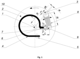
- FIG. 1 presents a schematic sketch of a crank mechanism according to the invention used in a gas meter with mechanical compensation of temperature.
- the crank mechanism according to the invention comprises a rotary part 1, on which a crank disc 2 is seated, both elements being placed coaxially.
- a crank element 3 which in the present case is intended to convert the reciprocating motion of the gas meter membrane into a rotary motion via levers, is placed on the crank disc 2 by means of intermediate elements.
- the crank element 3 is connected directly to a rigid crank 8, which is seated rotatably on the crank disc 2 via a rotary element 9.
- the crank 8 constitutes a support for the crank element 3.
- a compensating element 4 which in this case constitutes a bimetallic strip consisting of at least two mutually combined types of alloys with greatly differing thermal expansion coefficients, with a shape resembling a circle, is attached to the crank disc 2.
- the shape of the compensating element is adjusted so as to enable proper tilting, dependent on the temperature.
- One side of the compensating element 4 is attached to a handle 5 fixed in a non-rotary manner to the crank disc 2, while the second end of the compensating element 4 constitutes a free deformable arm 6.
- the rigid crank 8 has a pair of arms, among which the arm R connected to the crank element 3 is longer than the arm L connected to the compensating element 4.
- the arm R connected to the crank element 3 may be about two times longer than the arm L connected to the compensating element 4. Selecting the length of the rigid crank arms of the crank mechanism in such a way that the arm R connected to the crank element is longer than the arm L connected to the compensating element causes enhancement of the operation of the compensating element.
- the shorter arm L of the rigid crank 8 comprises resistance profiles 7, to which the free deformable arm 6 of the compensating element 4 is slidably connected.
- the compensating element 4 requires the introduction of certain mobility limitations. This results from the disproportional tilting of the deformable arm 6 of the compensating element 4, equally in the positive "T+” and negative “T-" directions of the impact of temperature on said compensating element 4 having the form of a bimetallic strip.
- the compensation method in a gas meter involves the fact that the meter has a crank mechanism used to accomplish compensation.
- the crank mechanism comprises a crank disc 2 which rotates using the axis of rotation 1.
- the compensating element 4 is attached by its first end to the crank disc 2.
- the second free end of the compensating element 4 constitutes a deformable arm 6, which arm is placed between two resistance profiles 7 of the rigid crank 8 seated rotatably in the crank disc 2 via the rotary element 9. Due to a change in temperature, the deformable arm 6 bends in the direction of "T+", i.e. for temperatures higher than the base temperature, or in the direction of "T-" for those lower than the base temperature, starting the rotary movement of the crank 8 by engaging the resistance profiles 7.
- the crank 8 follows changes in the temperature of gas surrounding the crank mechanism.
- the deformable arm 6 bends unobstructed in a direction opposite to the resistance part 10, while being constrained in the opposite direction by the resistance part 10.
- the rigid crank 8 changes the position of the crank element 3.
- the crank element 3 changes its position relative to the rotary part 1 of the crank disc 2. Due to the proper transmission ratio (the R/L relation) of the rigid crank 8, this motion is enhanced relative to the movement of the deformable arm 6 of the compensating element 4.
Landscapes
- Physics & Mathematics (AREA)
- Fluid Mechanics (AREA)
- General Physics & Mathematics (AREA)
- Measuring Volume Flow (AREA)
- Sampling And Sample Adjustment (AREA)
- Measuring Temperature Or Quantity Of Heat (AREA)
- Means For Warming Up And Starting Carburetors (AREA)
Priority Applications (2)
| Application Number | Priority Date | Filing Date | Title |
|---|---|---|---|
| RS20230839A RS64594B1 (sr) | 2019-06-17 | 2020-06-04 | Kolenasti mehanizam za merač gasa sa kompenzacijom temperature |
| HRP20230845TT HRP20230845T1 (hr) | 2019-06-17 | 2020-06-04 | Pogonski mehanizam za plinomjer s mehaničkom kompenzacijom temperature |
Applications Claiming Priority (1)
| Application Number | Priority Date | Filing Date | Title |
|---|---|---|---|
| PL430262A PL239968B1 (pl) | 2019-06-17 | 2019-06-17 | Mechanizm korbowy miernika gazu z kompensacją temperatury |
Publications (3)
| Publication Number | Publication Date |
|---|---|
| EP3754306A1 EP3754306A1 (en) | 2020-12-23 |
| EP3754306C0 EP3754306C0 (en) | 2023-07-05 |
| EP3754306B1 true EP3754306B1 (en) | 2023-07-05 |
Family
ID=72242909
Family Applications (1)
| Application Number | Title | Priority Date | Filing Date |
|---|---|---|---|
| EP20178159.8A Active EP3754306B1 (en) | 2019-06-17 | 2020-06-04 | A crank mechanism for a gas meter with the compensation of temperature |
Country Status (5)
| Country | Link |
|---|---|
| EP (1) | EP3754306B1 (pl) |
| HR (1) | HRP20230845T1 (pl) |
| HU (1) | HUE063159T2 (pl) |
| PL (1) | PL239968B1 (pl) |
| RS (1) | RS64594B1 (pl) |
Families Citing this family (1)
| Publication number | Priority date | Publication date | Assignee | Title |
|---|---|---|---|---|
| CN113091841B (zh) * | 2021-03-24 | 2024-01-30 | 上海真兰仪表科技股份有限公司 | 一种机械温补曲柄齿轮组合机构 |
Family Cites Families (8)
| Publication number | Priority date | Publication date | Assignee | Title |
|---|---|---|---|---|
| US3362223A (en) * | 1965-04-07 | 1968-01-09 | Lancaster Meter Parts Co | Gas meter crank assembly having thermally-responsive compensating means |
| PL120141B1 (en) | 1978-10-16 | 1982-02-27 | Pleszewska Fabryka Aparatury P | Apparatus for introducing a filling into a caramel mass |
| US4538458A (en) * | 1983-08-26 | 1985-09-03 | Rockwell International Corporation | Temperature compensated gas meters |
| US4747306A (en) * | 1986-05-16 | 1988-05-31 | American Meter Company | Temperature compensating tangent assembly for a diaphragm gas meter |
| DE19909025A1 (de) | 1999-03-02 | 2000-09-07 | Kromschoeder Ag G | Kurbeltrieb |
| PL210347B1 (pl) * | 2008-06-02 | 2012-01-31 | Apator Metrix Społka Akcyjna | Mechanizm korbowy miernika gazu |
| CN201697670U (zh) * | 2010-06-29 | 2011-01-05 | 重庆市山城燃气设备有限公司 | 凸轮拨叉驱动并带内藏式机械温度转换装置的膜式燃气表 |
| CN207248272U (zh) * | 2017-05-23 | 2018-04-17 | 杭州新立仪表有限公司 | 一种温度补偿装置 |
-
2019
- 2019-06-17 PL PL430262A patent/PL239968B1/pl unknown
-
2020
- 2020-06-04 EP EP20178159.8A patent/EP3754306B1/en active Active
- 2020-06-04 RS RS20230839A patent/RS64594B1/sr unknown
- 2020-06-04 HU HUE20178159A patent/HUE063159T2/hu unknown
- 2020-06-04 HR HRP20230845TT patent/HRP20230845T1/hr unknown
Also Published As
| Publication number | Publication date |
|---|---|
| PL430262A1 (pl) | 2020-12-28 |
| EP3754306A1 (en) | 2020-12-23 |
| HUE063159T2 (hu) | 2023-12-28 |
| HRP20230845T1 (hr) | 2023-11-10 |
| PL239968B1 (pl) | 2022-01-31 |
| EP3754306C0 (en) | 2023-07-05 |
| RS64594B1 (sr) | 2023-10-31 |
Similar Documents
| Publication | Publication Date | Title |
|---|---|---|
| EP3754306A1 (en) | A crank mechanism for a gas meter with the compensation of temperature | |
| CN107168030A (zh) | 对温度变化敏感的双金属装置 | |
| FR2601748A1 (fr) | Soupape de reglage de pression autoregulee | |
| US4538458A (en) | Temperature compensated gas meters | |
| JPS5845508A (ja) | 条件応答計器の運動増巾部 | |
| JP6484479B2 (ja) | バルブ用アクチュエータ | |
| CN201107069Y (zh) | 带机械温度转换装置膜式燃气表 | |
| US4747306A (en) | Temperature compensating tangent assembly for a diaphragm gas meter | |
| PL210347B1 (pl) | Mechanizm korbowy miernika gazu | |
| RU2230296C2 (ru) | Кривошипно-шатунный механизм | |
| CN209356076U (zh) | 一种带调零装置双金属温度计 | |
| US3710624A (en) | Meter volume compensating mechanism | |
| JP2022099365A (ja) | スライダクランク機構及び温度補正装置 | |
| CN209589282U (zh) | 一种表盘式双金属温度表 | |
| CN114442731A (zh) | 一种球面密封式三自由度操纵杆 | |
| US3369089A (en) | Displacement transmitting device | |
| GB2094002A (en) | Gauge instrument | |
| KR100209939B1 (ko) | 절대 압력계 | |
| US1195750A (en) | Reuben n | |
| JP7289885B2 (ja) | 回転式共振機構、特に、計時器用ムーブメント、のための並進運動構造を備えるフレキシブルガイド | |
| JP2022099363A (ja) | 温度補正装置 | |
| JP2009068706A (ja) | ガス供給バルブ | |
| CN110174149B (zh) | 煤气表计量温度补偿装置 | |
| JP2008202970A (ja) | 圧力計 | |
| SU1235724A1 (ru) | Рука робота (ее варианты) |
Legal Events
| Date | Code | Title | Description |
|---|---|---|---|
| REG | Reference to a national code |
Ref country code: HR Ref legal event code: TUEP Ref document number: P20230845T Country of ref document: HR |
|
| PUAI | Public reference made under article 153(3) epc to a published international application that has entered the european phase |
Free format text: ORIGINAL CODE: 0009012 |
|
| STAA | Information on the status of an ep patent application or granted ep patent |
Free format text: STATUS: THE APPLICATION HAS BEEN PUBLISHED |
|
| AK | Designated contracting states |
Kind code of ref document: A1 Designated state(s): AL AT BE BG CH CY CZ DE DK EE ES FI FR GB GR HR HU IE IS IT LI LT LU LV MC MK MT NL NO PL PT RO RS SE SI SK SM TR |
|
| AX | Request for extension of the european patent |
Extension state: BA ME |
|
| STAA | Information on the status of an ep patent application or granted ep patent |
Free format text: STATUS: REQUEST FOR EXAMINATION WAS MADE |
|
| 17P | Request for examination filed |
Effective date: 20201229 |
|
| RBV | Designated contracting states (corrected) |
Designated state(s): AL AT BE BG CH CY CZ DE DK EE ES FI FR GB GR HR HU IE IS IT LI LT LU LV MC MK MT NL NO PL PT RO RS SE SI SK SM TR |
|
| GRAP | Despatch of communication of intention to grant a patent |
Free format text: ORIGINAL CODE: EPIDOSNIGR1 |
|
| STAA | Information on the status of an ep patent application or granted ep patent |
Free format text: STATUS: GRANT OF PATENT IS INTENDED |
|
| GRAS | Grant fee paid |
Free format text: ORIGINAL CODE: EPIDOSNIGR3 |
|
| RIC1 | Information provided on ipc code assigned before grant |
Ipc: G01F 15/04 20060101ALI20230131BHEP Ipc: G01F 3/22 20060101AFI20230131BHEP |
|
| INTG | Intention to grant announced |
Effective date: 20230224 |
|
| RAP3 | Party data changed (applicant data changed or rights of an application transferred) |
Owner name: APATOR METRIX SPOLKA AKCYJNA |
|
| RIN1 | Information on inventor provided before grant (corrected) |
Inventor name: SPIEREWKA, SLAWOMIR |
|
| GRAA | (expected) grant |
Free format text: ORIGINAL CODE: 0009210 |
|
| STAA | Information on the status of an ep patent application or granted ep patent |
Free format text: STATUS: THE PATENT HAS BEEN GRANTED |
|
| AK | Designated contracting states |
Kind code of ref document: B1 Designated state(s): AL AT BE BG CH CY CZ DE DK EE ES FI FR GB GR HR HU IE IS IT LI LT LU LV MC MK MT NL NO PL PT RO RS SE SI SK SM TR |
|
| REG | Reference to a national code |
Ref country code: CH Ref legal event code: EP |
|
| REG | Reference to a national code |
Ref country code: AT Ref legal event code: REF Ref document number: 1585235 Country of ref document: AT Kind code of ref document: T Effective date: 20230715 |
|
| REG | Reference to a national code |
Ref country code: DE Ref legal event code: R096 Ref document number: 602020013208 Country of ref document: DE |
|
| REG | Reference to a national code |
Ref country code: IE Ref legal event code: FG4D |
|
| U01 | Request for unitary effect filed |
Effective date: 20230724 |
|
| U07 | Unitary effect registered |
Designated state(s): AT BE BG DE DK EE FI FR IT LT LU LV MT NL PT SE SI Effective date: 20230727 |
|
| REG | Reference to a national code |
Ref country code: RO Ref legal event code: EPE |
|
| REG | Reference to a national code |
Ref country code: SK Ref legal event code: T3 Ref document number: E 41908 Country of ref document: SK |
|
| REG | Reference to a national code |
Ref country code: LT Ref legal event code: MG9D |
|
| REG | Reference to a national code |
Ref country code: GR Ref legal event code: EP Ref document number: 20230401325 Country of ref document: GR Effective date: 20231010 |
|
| REG | Reference to a national code |
Ref country code: HR Ref legal event code: T1PR Ref document number: P20230845 Country of ref document: HR |
|
| REG | Reference to a national code |
Ref country code: HU Ref legal event code: AG4A Ref document number: E063159 Country of ref document: HU |
|
| PG25 | Lapsed in a contracting state [announced via postgrant information from national office to epo] |
Ref country code: ES Free format text: LAPSE BECAUSE OF FAILURE TO SUBMIT A TRANSLATION OF THE DESCRIPTION OR TO PAY THE FEE WITHIN THE PRESCRIBED TIME-LIMIT Effective date: 20230705 |
|
| PG25 | Lapsed in a contracting state [announced via postgrant information from national office to epo] |
Ref country code: IS Free format text: LAPSE BECAUSE OF FAILURE TO SUBMIT A TRANSLATION OF THE DESCRIPTION OR TO PAY THE FEE WITHIN THE PRESCRIBED TIME-LIMIT Effective date: 20231105 |
|
| PG25 | Lapsed in a contracting state [announced via postgrant information from national office to epo] |
Ref country code: NO Free format text: LAPSE BECAUSE OF FAILURE TO SUBMIT A TRANSLATION OF THE DESCRIPTION OR TO PAY THE FEE WITHIN THE PRESCRIBED TIME-LIMIT Effective date: 20231005 Ref country code: IS Free format text: LAPSE BECAUSE OF FAILURE TO SUBMIT A TRANSLATION OF THE DESCRIPTION OR TO PAY THE FEE WITHIN THE PRESCRIBED TIME-LIMIT Effective date: 20231105 Ref country code: ES Free format text: LAPSE BECAUSE OF FAILURE TO SUBMIT A TRANSLATION OF THE DESCRIPTION OR TO PAY THE FEE WITHIN THE PRESCRIBED TIME-LIMIT Effective date: 20230705 |
|
| PG25 | Lapsed in a contracting state [announced via postgrant information from national office to epo] |
Ref country code: PL Free format text: LAPSE BECAUSE OF FAILURE TO SUBMIT A TRANSLATION OF THE DESCRIPTION OR TO PAY THE FEE WITHIN THE PRESCRIBED TIME-LIMIT Effective date: 20230705 |
|
| REG | Reference to a national code |
Ref country code: DE Ref legal event code: R097 Ref document number: 602020013208 Country of ref document: DE |
|
| PG25 | Lapsed in a contracting state [announced via postgrant information from national office to epo] |
Ref country code: SM Free format text: LAPSE BECAUSE OF FAILURE TO SUBMIT A TRANSLATION OF THE DESCRIPTION OR TO PAY THE FEE WITHIN THE PRESCRIBED TIME-LIMIT Effective date: 20230705 Ref country code: CZ Free format text: LAPSE BECAUSE OF FAILURE TO SUBMIT A TRANSLATION OF THE DESCRIPTION OR TO PAY THE FEE WITHIN THE PRESCRIBED TIME-LIMIT Effective date: 20230705 |
|
| U20 | Renewal fee for the european patent with unitary effect paid |
Year of fee payment: 5 Effective date: 20240331 |
|
| PLBE | No opposition filed within time limit |
Free format text: ORIGINAL CODE: 0009261 |
|
| STAA | Information on the status of an ep patent application or granted ep patent |
Free format text: STATUS: NO OPPOSITION FILED WITHIN TIME LIMIT |
|
| REG | Reference to a national code |
Ref country code: HR Ref legal event code: ODRP Ref document number: P20230845 Country of ref document: HR Payment date: 20240214 Year of fee payment: 5 |
|
| 26N | No opposition filed |
Effective date: 20240408 |
|
| PG25 | Lapsed in a contracting state [announced via postgrant information from national office to epo] |
Ref country code: MC Free format text: LAPSE BECAUSE OF FAILURE TO SUBMIT A TRANSLATION OF THE DESCRIPTION OR TO PAY THE FEE WITHIN THE PRESCRIBED TIME-LIMIT Effective date: 20230705 |
|
| REG | Reference to a national code |
Ref country code: CH Ref legal event code: PL |
|
| GBPC | Gb: european patent ceased through non-payment of renewal fee |
Effective date: 20240604 |
|
| PG25 | Lapsed in a contracting state [announced via postgrant information from national office to epo] |
Ref country code: IE Free format text: LAPSE BECAUSE OF NON-PAYMENT OF DUE FEES Effective date: 20240604 |
|
| PG25 | Lapsed in a contracting state [announced via postgrant information from national office to epo] |
Ref country code: CH Free format text: LAPSE BECAUSE OF NON-PAYMENT OF DUE FEES Effective date: 20240630 |
|
| PG25 | Lapsed in a contracting state [announced via postgrant information from national office to epo] |
Ref country code: GB Free format text: LAPSE BECAUSE OF NON-PAYMENT OF DUE FEES Effective date: 20240604 |
|
| REG | Reference to a national code |
Ref country code: HR Ref legal event code: ODRP Ref document number: P20230845 Country of ref document: HR Payment date: 20250505 Year of fee payment: 6 |
|
| U20 | Renewal fee for the european patent with unitary effect paid |
Year of fee payment: 6 Effective date: 20250522 |
|
| PGFP | Annual fee paid to national office [announced via postgrant information from national office to epo] |
Ref country code: HU Payment date: 20250526 Year of fee payment: 6 |
|
| PGFP | Annual fee paid to national office [announced via postgrant information from national office to epo] |
Ref country code: RO Payment date: 20250603 Year of fee payment: 6 |
|
| PG25 | Lapsed in a contracting state [announced via postgrant information from national office to epo] |
Ref country code: CY Free format text: LAPSE BECAUSE OF FAILURE TO SUBMIT A TRANSLATION OF THE DESCRIPTION OR TO PAY THE FEE WITHIN THE PRESCRIBED TIME-LIMIT; INVALID AB INITIO Effective date: 20200604 |
|
| PGFP | Annual fee paid to national office [announced via postgrant information from national office to epo] |
Ref country code: HR Payment date: 20260304 Year of fee payment: 7 |
|
| PGFP | Annual fee paid to national office [announced via postgrant information from national office to epo] |
Ref country code: RS Payment date: 20260311 Year of fee payment: 7 |
|
| PGFP | Annual fee paid to national office [announced via postgrant information from national office to epo] |
Ref country code: TR Payment date: 20260304 Year of fee payment: 7 |
|
| PGFP | Annual fee paid to national office [announced via postgrant information from national office to epo] |
Ref country code: GR Payment date: 20260313 Year of fee payment: 7 |
|
| PGFP | Annual fee paid to national office [announced via postgrant information from national office to epo] |
Ref country code: SK Payment date: 20260319 Year of fee payment: 7 |
|
| PGFP | Annual fee paid to national office [announced via postgrant information from national office to epo] |
Ref country code: MK Payment date: 20260305 Year of fee payment: 7 |