EP3754262A1 - A door for a household appliance - Google Patents
A door for a household appliance Download PDFInfo
- Publication number
- EP3754262A1 EP3754262A1 EP20176084.0A EP20176084A EP3754262A1 EP 3754262 A1 EP3754262 A1 EP 3754262A1 EP 20176084 A EP20176084 A EP 20176084A EP 3754262 A1 EP3754262 A1 EP 3754262A1
- Authority
- EP
- European Patent Office
- Prior art keywords
- door
- pane
- retaining part
- retaining
- guiding channel
- Prior art date
- Legal status (The legal status is an assumption and is not a legal conclusion. Google has not performed a legal analysis and makes no representation as to the accuracy of the status listed.)
- Withdrawn
Links
Images




Classifications
-
- F—MECHANICAL ENGINEERING; LIGHTING; HEATING; WEAPONS; BLASTING
- F24—HEATING; RANGES; VENTILATING
- F24C—DOMESTIC STOVES OR RANGES ; DETAILS OF DOMESTIC STOVES OR RANGES, OF GENERAL APPLICATION
- F24C15/00—Details
- F24C15/02—Doors specially adapted for stoves or ranges
- F24C15/04—Doors specially adapted for stoves or ranges with transparent panels
Definitions
- the present invention relates to a door for a household appliance, particularly for an oven, comprising a plurality of door panes spaced apart each other, a pair of pane holding columns provided on opposite sides of the door, each pane holding column having at least one guiding channel configured to guide an edge portion of the associated door pane.
- EP2662635 A1 discloses an appliance having a cooking chamber including a feed aperture, where the feed aperture is closed by a door.
- the door includes a frame with two supporting rail sections, where two surface components are arranged on the two supporting rail sections.
- the frame includes two spacer units, where one of the spacer units is made flexible, so as to align the surface components relative to the rail sections.
- the spacer units are movable secured at the supporting rail sections, where the spacer units are formed from a curved sheet metal.
- the invention provides an additional improvement, an additional advantage or an alternative to the prior art.
- the purpose of the present invention is to provide a door for a household appliance, particularly for an oven, having easily and securely mountable and removable door panes.
- a door for a household appliance particularly for an oven, comprising a plurality of door panes spaced apart each other, a pair of pane holding columns provided on opposite sides of the door, each pane holding column having at least one guiding channel configured to guide an edge portion of the associated door pane.
- the door further comprises at least one retaining part, which is being attached to the guiding channel in order to retain at least a part of the edge portion of the associated door pane in a firmly manner.
- the users can easily and securely remove the associated door pane from the pane holding columns, clean the surfaces of said door pane, and then easily and securely mount the associated door pane to the pane holding columns.
- the term "at least a part of the edge portion” means the retaining part retains along the edge portion or along a part of the edge portion.
- the retaining part extends along at least a part of the guiding channel.
- the retaining part retains the associated door pane along at least a part of the guiding channel in a firmly manner.
- the term "at least a part of the guiding channel” means the retaining part extends along the guiding channel or along a part of the guiding channel.
- the retaining part is configured to be attached to a side of the guiding channel such a way that the retaining part is being on a side of the door where a detachable top cover extending perpendicular to the pane holding columns is provided.
- the top cover hides the retaining part and an aesthetic door appearance is provided.
- the retaining part shaped and sized with respect to the guiding channel has a retaining channel extending along said retaining part for receiving the edge portion of the associated door pane.
- the edge portion of the associated door pane can be retained by the retaining part. Therefore, the associated door pane can be retained by the retaining part in a secure manner.
- a width of the retaining channel provided between the opposite side walls of the retaining part is greater than a thickness of the associated door pane so as to receive the edge portion of the associated door pane in a firmly manner.
- the edge portion of the associated door pane can be received by the retaining channel in a firmly manner.
- the retaining part has at least one guiding section guiding the associated door pane towards the retaining channel.
- associated door pane can easily be attached to the retaining part.
- the retaining part has at least one blocking wall in order to block the movement of the retaining part, when the retaining part moved towards the guiding channel for attaching said retaining part to the guiding channel.
- blocking wall blocks the sliding movement of the retaining part, when the retaining part moved towards the guiding channel. Therefore, the possible undesired movements of the retaining part in the height direction of the door, is prevented.
- the retaining part has at least one attachment protrusion extending in a direction perpendicular to the blocking wall, wherein the pane holding column has at least one attachment channel provided in a direction along the guiding channel and wherein the attachment protrusions attach to the attachment channels, when the retaining part moved towards the guiding channel.
- the retaining part attaches to the guiding channel of the pane holding column.
- possible undesired movements of the retaining part in the width direction of the door is prevented.
- an outer door pane whereon the pane holding columns are secured is provided so as not to be guided by the guiding channels.
- the outer door pane is provided with a greater width than the other door panes. Therefore, an aesthetic door appearance with the width of the outer door pane equal to the width of the household appliance can be provided.
- At least one intermediate door pane is provided between the outer door pane and an inner door pane spaced apart from the outer door pane.
- At least two pair of guiding channels are provided where the retaining parts can be attached for retaining both opposite edge portions of the inner door pane and at least one intermediate door pane.
- the inner door pane and at least one intermediate door pane can easily and securely be mounted to the pane holding columns.
- mentioned door panes can easily and securely be removed from the pane holding columns.
- the household appliance for preparing food particularly an oven, with a door.
- a door (4) is explained to be applied to an oven given in Fig. 1 .
- the same embodiment can be applied to any kind of household appliance, for example a washing machine, a refrigerator, a dishwasher, where the multiple door panes can be needed.
- Height direction (h), which is shown in Fig. 1 and 2 corresponds to a direction of a height of the door (4) and a direction of the height of the household appliance, particularly of an oven (1), mentioned in this document.
- Width direction (w), which is shown in Fig. 1 and 2 corresponds to a direction of a width of the door (4) and the direction of a height of the household appliance, particularly of an oven (1), mentioned in this document.
- Depth direction (d), which is shown in Fig. 1 and 2 corresponds to a direction of a depth of the door (4) and the direction of the depth of the household appliance, particularly of an oven, mentioned in this document.
- the exemplary oven (1) comprises a body (2) and a control panel (3) provided on the body (2). Said control panel (3) extends in the width direction (w) of the oven (1).
- the oven (1) further comprises a cooking chamber (not shown in figures) where the foodstuffs can be located for a cooking operation, surrounded by the body (2).
- the cooking chamber has an opening (not shown in figures) provided on a front side of the oven (1) for reaching the cooking chamber.
- a door (4) is also provided at the front side of the oven (1). In a possible embodiment, the door (4) is hinged to the body (2).
- Said door (4) covers the opening of the cooking chamber at a closed position such a way that it is extending in a height direction (h) and a width direction (w) of the oven (1).
- a handle (8) that can be gripped by users for opening or closing the door (4), is provided at an outer side of the door (4).
- the door (4) of the oven (1) comprises an outer door pane (5) facing outside and an inner door pane (6) spaced apart therefrom.
- the inner door pane (6) and the outer door pane (5) are arranged parallel to each other.
- the inner door pane (6) and the outer door pane (5) are arranged so that a gap (12) is provided in between.
- the inner door pane (6) is being the door pane closest to the cooking chamber.
- at least one intermediate door pane (7) can be placed between the outer door pane (5) and the inner door pane (6).
- the intermediate door pane (7) is also arranged parallel to the outer door pane (5) and the inner door pane (6).
- the outer door pane (5), the inner door pane (6) and the intermediate door pane (7) are made of a glass material.
- the mutual pane holding columns (10) configured to hold and guide the both opposite edge portions (13) of the associated door pane.
- two pane holding columns (10) are placed parallel to each other on an opposite sides of the door (4).
- the pane holding columns (10) extend in the height direction (h) of the door (4) longitudinally, when the door (4) is at the closed position.
- Said pane holding columns (10) are made of a metal material.
- said metal material is being aluminum.
- Said pane holding columns (10) are connected to outer door pane (5).
- the pane holding columns (10) have a connection surface (101) facing the outer door pane (5) to connect said pane holding columns (10) to the outer door pane (5).
- said pane holding columns (10) are glued from said connection surface (101) to the outer door pane (5).
- a top cover (9) comprising a plurality of ventilation opening through which an airflow can pass, is arranged to cover an aperture of the gap (12) provided in between the door panes (5, 6, 7).
- the gap (12) is provided in between the outer door pane (5) and the intermediate door pane (7), and in between the intermediate door pane (7) and the inner door pane (6).
- Said top cover (9) extends in the width direction (w) of the door (4).
- each pane holding columns (10) have at least one guiding channel (102) configured to guide both opposite edge portions (13) of the associated door pane.
- each pane holding columns (10) has at least two guiding channels (102). There are two pane holding columns (10) which are connected to the outer door pane (5). Said at least a pair of guiding channels (102) are configured so as to extend in the height direction (h), when the door is at the closed position. In a possible embodiment, said guiding channels are configured to guide and hold the inner door pane (6) and the intermediate door pane (7). Thus, the inner door pane (6) and the intermediate door pane (7) can be slid in the height direction (h) between mutual pane holding columns (10).
- the retaining parts (11) can be attached for retaining both opposite edge portions (13) of the inner door pane (6) and at least one intermediate door pane (7).
- Said retaining part (11) is shaped and sized with respect to the guiding channel (102).
- the retaining parts (11) are being attached to the guiding channels (102) in order to retain the edge portions (13) of the inner door pane (6) and the intermediate door pane (7) in a firmly manner.
- the retaining part (11) attaches to the associated guiding channel (102), when said retaining part (11) moved in a direction towards the associated guiding channel (102).
- the retaining part (11) extends along at least a part of the guiding channel (102), when the retaining part (11) attached to the guiding channel (102).
- the door (4) further comprises a detachable top cover (9) extending perpendicular to the pane holding columns (10).
- the retaining part (11) attaches to a side of the guiding channel (102) such a way that the retaining part (11) is being on a side of the door (4) where the detachable top cover (9) is provided.
- the retaining part (11) has a retaining channel (111) extending along said retaining part (11) for receiving the edge portion (13) of the associated door pane.
- the retaining part (11) has at least one blocking wall (115) in order to block the movement of the retaining part (11), when the retaining part (11) moved towards the guiding channel (102) for attaching said retaining part (11) to the guiding channel (102). Said blocking wall (115) extends in the width direction (w) of the door (4).
- the retaining part (11) comprises opposite side wall (116) provided on opposite sides of said retaining part (11).
- a width of the retaining channel (111) provided between said opposite side walls (116) of the retaining part (11) is greater than a thickness (t) of the associated door pane (5, 6, 7) so as to receive the edge portion (13) of the associated door pane (5, 6, 7) in a firmly manner.
- the subject-matter retaining part (11) has at least one attachment protrusion (114) extending in a direction perpendicular to the blocking wall (115).
- the pane holding column (10) has at least one attachment channel (103) provided in a direction along the guiding channel (102).
- the guiding channel (102) is formed as a T-shaped form.
- the attachment protrusions (114) attach to the attachment channels (103), when the retaining part (11) moved towards the guiding channel (102).
- a resting groove (112) is configured both opposite sides of the retaining part (11).
- the walls of said resting groove (112) is configured as the blocking wall (115) and the attachment protrusions (114).
- a side surface of the pane holding column (10) facing the guiding channel (102) rests said resting groove (112).
- the retaining part (11) has at least one guiding section (113) which guides the associated door pane towards the retaining channel (111).
- Said guiding section (113) is formed at an end section of the retaining part (11).
- two guiding sections (133) are configured on the surfaces of the opposite side walls (116) facing each other.
- the retaining part (11) can be made of any kind of plastic material or a rubber material.
Landscapes
- Engineering & Computer Science (AREA)
- Chemical & Material Sciences (AREA)
- Combustion & Propulsion (AREA)
- Mechanical Engineering (AREA)
- General Engineering & Computer Science (AREA)
- Electric Ovens (AREA)
Abstract
Description
- The present invention relates to a door for a household appliance, particularly for an oven, comprising a plurality of door panes spaced apart each other, a pair of pane holding columns provided on opposite sides of the door, each pane holding column having at least one guiding channel configured to guide an edge portion of the associated door pane.
- The patent application numbered
EP2662635 A1 discloses an appliance having a cooking chamber including a feed aperture, where the feed aperture is closed by a door. The door includes a frame with two supporting rail sections, where two surface components are arranged on the two supporting rail sections. The frame includes two spacer units, where one of the spacer units is made flexible, so as to align the surface components relative to the rail sections. The spacer units are movable secured at the supporting rail sections, where the spacer units are formed from a curved sheet metal. - The invention provides an additional improvement, an additional advantage or an alternative to the prior art.
- The purpose of the present invention is to provide a door for a household appliance, particularly for an oven, having easily and securely mountable and removable door panes.
- The present invention, to achieve the abovementioned purpose, a door for a household appliance, particularly for an oven, comprising a plurality of door panes spaced apart each other, a pair of pane holding columns provided on opposite sides of the door, each pane holding column having at least one guiding channel configured to guide an edge portion of the associated door pane. The door further comprises at least one retaining part, which is being attached to the guiding channel in order to retain at least a part of the edge portion of the associated door pane in a firmly manner. Thus, the frictions between the associated door pane and the pane holding column are reduced. Therefore, the associated door pane can easily and securely be mounted to the pane holding columns. Moreover, associated door pane can easily and securely be removed from the pane holding columns. Furthermore, possible scratches which can occur on the door panes during mounting or removing operations of the door panes, are prevented. In the invention, the users can easily and securely remove the associated door pane from the pane holding columns, clean the surfaces of said door pane, and then easily and securely mount the associated door pane to the pane holding columns.
- Here, the term "at least a part of the edge portion" means the retaining part retains along the edge portion or along a part of the edge portion.
- In a possible embodiment of the invention, the retaining part extends along at least a part of the guiding channel. Thus, the retaining part retains the associated door pane along at least a part of the guiding channel in a firmly manner.
Here, the term "at least a part of the guiding channel" means the retaining part extends along the guiding channel or along a part of the guiding channel. - In a possible embodiment of the invention, the retaining part is configured to be attached to a side of the guiding channel such a way that the retaining part is being on a side of the door where a detachable top cover extending perpendicular to the pane holding columns is provided. Thus, the top cover hides the retaining part and an aesthetic door appearance is provided.
- In a possible embodiment of the invention, the retaining part shaped and sized with respect to the guiding channel, has a retaining channel extending along said retaining part for receiving the edge portion of the associated door pane. Thus, the edge portion of the associated door pane can be retained by the retaining part. Therefore, the associated door pane can be retained by the retaining part in a secure manner.
- In a possible embodiment of the invention, a width of the retaining channel provided between the opposite side walls of the retaining part is greater than a thickness of the associated door pane so as to receive the edge portion of the associated door pane in a firmly manner. Thus, the edge portion of the associated door pane can be received by the retaining channel in a firmly manner.
- In a possible embodiment of the invention, the retaining part has at least one guiding section guiding the associated door pane towards the retaining channel. Thus, associated door pane can easily be attached to the retaining part.
- In a possible embodiment of the invention, the retaining part has at least one blocking wall in order to block the movement of the retaining part, when the retaining part moved towards the guiding channel for attaching said retaining part to the guiding channel. Thus, blocking wall blocks the sliding movement of the retaining part, when the retaining part moved towards the guiding channel. Therefore, the possible undesired movements of the retaining part in the height direction of the door, is prevented.
- In a possible embodiment of the invention, the retaining part has at least one attachment protrusion extending in a direction perpendicular to the blocking wall, wherein the pane holding column has at least one attachment channel provided in a direction along the guiding channel and wherein the attachment protrusions attach to the attachment channels, when the retaining part moved towards the guiding channel. Thus, the retaining part attaches to the guiding channel of the pane holding column. Moreover, possible undesired movements of the retaining part in the width direction of the door, is prevented.
- In a possible embodiment of the invention, an outer door pane whereon the pane holding columns are secured, is provided so as not to be guided by the guiding channels. Thus, the outer door pane is provided with a greater width than the other door panes. Therefore, an aesthetic door appearance with the width of the outer door pane equal to the width of the household appliance can be provided.
- In a possible embodiment of the invention, at least one intermediate door pane is provided between the outer door pane and an inner door pane spaced apart from the outer door pane. Thus, a door having multiple door panes, is provided.
- In a possible embodiment of the invention, at least two pair of guiding channels are provided where the retaining parts can be attached for retaining both opposite edge portions of the inner door pane and at least one intermediate door pane. Thus, the inner door pane and at least one intermediate door pane can easily and securely be mounted to the pane holding columns. Moreover, mentioned door panes can easily and securely be removed from the pane holding columns.
- In a possible embodiment of the invention, the household appliance for preparing food, particularly an oven, with a door.
- Further advantages may become apparent from the following description of the figure(s). In the figure, an exemplary embodiment of the invention is shown. The figure, the description and the claims contain a plurality of features in combination. The person having ordinary skill in the art will purposefully also consider the features separately and will find further expedient combinations.
- If there is more than one specimen of a certain object, only one of these is given a reference numeral in the figures and in the description. The description of this specimen may be correspondingly transferred to the other specimens of the object.
- In this context, with the indications "front", "upper", "below", "top", "bottom", "rear", "outer, "inner" etc. the positions and orientations given for intended use and intended arrangement of the household appliance and for a user then standing in front of the household appliance in a closed position and viewing in the direction of the appliance are indicated.
- The figures, whose brief explanations are herewith provided, are solely intended for providing a better understanding of the present invention and are as such not intended to define the scope of protection or the context in which said scope is to be interpreted in the absence of the description.
-
Fig. 1 represents a front view of the exemplary home appliance which is designed in particular as an oven having a door. -
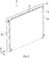
Fig. 2 represents an isometric view of the exemplary door of the oven. -
Fig. 3 represents a top view of the exemplary door having the subject-matter retaining part. -
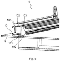
Fig. 4 represents a zoomed isometric view of the exemplary door where the pane holding column secured to the outer door pane. -
Fig. 5 represents an another zoomed isometric view of the exemplary door where the subject-matter retaining part is being attached to a guiding channel of the pane holding column -
Fig. 6 represents a partially exploded view of the exemplary door having the subject-matter retaining part. -
Fig. 7 represents an isometric view of the subject-matter retaining part. - In this detailed explanation, the invented subject-matter is explained with examples in order to make the subject more understandable without forming any restrictive effect. According to this, in the detailed explanation below, a door (4) is explained to be applied to an oven given in
Fig. 1 . However, the same embodiment can be applied to any kind of household appliance, for example a washing machine, a refrigerator, a dishwasher, where the multiple door panes can be needed. - Height direction (h), which is shown in
Fig. 1 and2 , corresponds to a direction of a height of the door (4) and a direction of the height of the household appliance, particularly of an oven (1), mentioned in this document. Width direction (w), which is shown inFig. 1 and2 , corresponds to a direction of a width of the door (4) and the direction of a height of the household appliance, particularly of an oven (1), mentioned in this document. Depth direction (d), which is shown inFig. 1 and2 , corresponds to a direction of a depth of the door (4) and the direction of the depth of the household appliance, particularly of an oven, mentioned in this document. - As shown in
Fig. 1 , the exemplary oven (1) comprises a body (2) and a control panel (3) provided on the body (2). Said control panel (3) extends in the width direction (w) of the oven (1). The oven (1) further comprises a cooking chamber (not shown in figures) where the foodstuffs can be located for a cooking operation, surrounded by the body (2). The cooking chamber has an opening (not shown in figures) provided on a front side of the oven (1) for reaching the cooking chamber. A door (4) is also provided at the front side of the oven (1). In a possible embodiment, the door (4) is hinged to the body (2). Said door (4) covers the opening of the cooking chamber at a closed position such a way that it is extending in a height direction (h) and a width direction (w) of the oven (1). A handle (8) that can be gripped by users for opening or closing the door (4), is provided at an outer side of the door (4). - As shown in
Fig. 2 , the door (4) of the oven (1) comprises an outer door pane (5) facing outside and an inner door pane (6) spaced apart therefrom. The inner door pane (6) and the outer door pane (5) are arranged parallel to each other. In more details, as can be seen inFig. 5 , the inner door pane (6) and the outer door pane (5) are arranged so that a gap (12) is provided in between. When the door (4) is at the closed position, the inner door pane (6) is being the door pane closest to the cooking chamber. As shown inFig. 3 , at least one intermediate door pane (7) can be placed between the outer door pane (5) and the inner door pane (6). The intermediate door pane (7) is also arranged parallel to the outer door pane (5) and the inner door pane (6). In a possible embodiment, the outer door pane (5), the inner door pane (6) and the intermediate door pane (7) are made of a glass material. On the other hand, the mutual pane holding columns (10) configured to hold and guide the both opposite edge portions (13) of the associated door pane. In a possible embodiment, two pane holding columns (10) are placed parallel to each other on an opposite sides of the door (4). In more details, the pane holding columns (10) extend in the height direction (h) of the door (4) longitudinally, when the door (4) is at the closed position. Said pane holding columns (10) are made of a metal material. Preferably, said metal material is being aluminum. Said pane holding columns (10) are connected to outer door pane (5). In more details, as can be seen inFig. 4 , the pane holding columns (10) have a connection surface (101) facing the outer door pane (5) to connect said pane holding columns (10) to the outer door pane (5). Preferably, said pane holding columns (10) are glued from said connection surface (101) to the outer door pane (5). As shown inFig. 2 , a top cover (9) comprising a plurality of ventilation opening through which an airflow can pass, is arranged to cover an aperture of the gap (12) provided in between the door panes (5, 6, 7). In more details, the gap (12) is provided in between the outer door pane (5) and the intermediate door pane (7), and in between the intermediate door pane (7) and the inner door pane (6). Said top cover (9) extends in the width direction (w) of the door (4). As can be seen inFig. 3 and4 , each pane holding columns (10) have at least one guiding channel (102) configured to guide both opposite edge portions (13) of the associated door pane. - As can be seen in
Fig. 3 and4 , in a possible embodiment of the invention, each pane holding columns (10) has at least two guiding channels (102). There are two pane holding columns (10) which are connected to the outer door pane (5). Said at least a pair of guiding channels (102) are configured so as to extend in the height direction (h), when the door is at the closed position. In a possible embodiment, said guiding channels are configured to guide and hold the inner door pane (6) and the intermediate door pane (7). Thus, the inner door pane (6) and the intermediate door pane (7) can be slid in the height direction (h) between mutual pane holding columns (10). In a possible embodiment of the invention, the retaining parts (11) can be attached for retaining both opposite edge portions (13) of the inner door pane (6) and at least one intermediate door pane (7). Said retaining part (11) is shaped and sized with respect to the guiding channel (102). - With reference to
Fig. 5 and6 , the retaining parts (11) are being attached to the guiding channels (102) in order to retain the edge portions (13) of the inner door pane (6) and the intermediate door pane (7) in a firmly manner. In more details, the retaining part (11) attaches to the associated guiding channel (102), when said retaining part (11) moved in a direction towards the associated guiding channel (102). In a possible embodiment, the retaining part (11) extends along at least a part of the guiding channel (102), when the retaining part (11) attached to the guiding channel (102). As can be seen inFig. 2 , the door (4) further comprises a detachable top cover (9) extending perpendicular to the pane holding columns (10). In a possible embodiment, the retaining part (11) attaches to a side of the guiding channel (102) such a way that the retaining part (11) is being on a side of the door (4) where the detachable top cover (9) is provided. As shown inFig. 5 and7 , the retaining part (11) has a retaining channel (111) extending along said retaining part (11) for receiving the edge portion (13) of the associated door pane. In a possible embodiment of the invention, the retaining part (11) has at least one blocking wall (115) in order to block the movement of the retaining part (11), when the retaining part (11) moved towards the guiding channel (102) for attaching said retaining part (11) to the guiding channel (102). Said blocking wall (115) extends in the width direction (w) of the door (4). - With reference to
Fig. 7 , the retaining part (11) comprises opposite side wall (116) provided on opposite sides of said retaining part (11). In a possible embodiment, a width of the retaining channel (111) provided between said opposite side walls (116) of the retaining part (11) is greater than a thickness (t) of the associated door pane (5, 6, 7) so as to receive the edge portion (13) of the associated door pane (5, 6, 7) in a firmly manner. The subject-matter retaining part (11) has at least one attachment protrusion (114) extending in a direction perpendicular to the blocking wall (115). Moreover, the pane holding column (10) has at least one attachment channel (103) provided in a direction along the guiding channel (102). Preferably, the guiding channel (102) is formed as a T-shaped form. In a possible embodiment, the attachment protrusions (114) attach to the attachment channels (103), when the retaining part (11) moved towards the guiding channel (102). In a possible embodiment, a resting groove (112) is configured both opposite sides of the retaining part (11). The walls of said resting groove (112) is configured as the blocking wall (115) and the attachment protrusions (114). A side surface of the pane holding column (10) facing the guiding channel (102) rests said resting groove (112). Furthermore, the retaining part (11) has at least one guiding section (113) which guides the associated door pane towards the retaining channel (111). Said guiding section (113) is formed at an end section of the retaining part (11). In a possible embodiment, two guiding sections (133) are configured on the surfaces of the opposite side walls (116) facing each other. - In a possible embodiment of the invention, the retaining part (11) can be made of any kind of plastic material or a rubber material.
-
- 1. Oven
- 2. Body
- 3. Control panel
- 4. Door
- 5. Outer door pane
- 6. Inner door pane
- 7. Intermediate door pane
- 8. Handle
- 9. Top cover
- 10. Pane holding column
- 101. Connection surface
- 102. Guiding channel
- 103. Attachment channel
- 104. Side wall
- 11. Retaining part
- 111. Retaining channel
- 112. Resting groove
- 113. Guiding section
- 114. Attachment protrusion
- 115. Blocking wall
- 116. Opposite side walls
- 12. Gap
- 13. Edge portion
- h. height direction
- w. width direction
- d. depth direction
- t. thickness
Claims (12)
- A door (4) for a household appliance, particularly for an oven, comprising a plurality of door panes (5, 6, 7) spaced apart each other, a pair of pane holding columns (10) provided on opposite sides of the door, each pane holding column (10) having at least one guiding channel (102) configured to guide an edge portion (13) of the associated door pane (5, 6, 7),
characterized in that
the door (4) further comprises at least one retaining part (11), which is being attached to the guiding channel (102) in order to retain at least a part of the edge portion (13) of the associated door pane (5, 6, 7) in a firmly manner. - The door (4) according to Claim 1, wherein the retaining part (11) extends along at least a part of the guiding channel (102).
- The door (4) according to Claim 1 or 2, wherein the retaining part (11) is configured to be attached to a side of the guiding channel (102) such a way that the retaining part (11) is being on a side of the door (4) where a detachable top cover (9) extending perpendicular to the pane holding columns (10) is provided.
- The door (4) according to any one of the preceding claims, wherein the retaining part (11) shaped and sized with respect to the guiding channel (102), has a retaining channel (111) extending along said retaining part (11) for receiving the edge portion (13) of the associated door pane (5, 6, 7).
- The door (4) according to Claim 4, wherein a width of the retaining channel (111) provided between the opposite side walls (116) of the retaining part (11) is greater than a thickness (t) of the associated door pane (5, 6, 7) so as to receive the edge portion (13) of the associated door pane (5, 6, 7) in a firmly manner.
- The door (4) according to Claim 4 or 5, wherein the retaining part (11) has at least one guiding section (113) guiding the associated door pane (5, 6, 7) towards the retaining channel (111).
- The door (4) according to Claim 1, wherein the retaining part (11) has at least one blocking wall (115) in order to block the movement of the retaining part (11), when the retaining part (11) moved towards the guiding channel (102) for attaching said retaining part (11) to the guiding channel (102).
- The door (4) according to Claim 7, wherein the retaining part (11) has at least one attachment protrusion (114) extending in a direction perpendicular to the blocking wall (115), wherein the pane holding column (10) has at least one attachment channel (103) provided in a direction along the guiding channel (102) and wherein the attachment protrusions (114) attach to the attachment channels (103), when the retaining part (11) moved towards the guiding channel (102).
- The door (4) according to any one of the preceding claims, wherein an outer door pane (5) whereon the pane holding columns (10) are secured, is provided so as not to be guided by the guiding channels (102).
- The door (4) according to Claim 9, wherein at least one intermediate door pane (7) is provided between the outer door pane (5) and an inner door pane (6) spaced apart from the outer door pane (5).
- The door (4) according to Claim 10, wherein at least two pair of guiding channels (102) are provided where the retaining parts (11) can be attached for retaining both opposite edge portions of the inner door pane (6) and at least one intermediate door pane (7).
- The household appliance for preparing food, particularly an oven (1), with a door (4) according to any one of the preceding claims.
Applications Claiming Priority (1)
| Application Number | Priority Date | Filing Date | Title |
|---|---|---|---|
| TR2019/09193A TR201909193A2 (en) | 2019-06-20 | 2019-06-20 | ONE DOOR FOR HOME APPLIANCE |
Publications (1)
| Publication Number | Publication Date |
|---|---|
| EP3754262A1 true EP3754262A1 (en) | 2020-12-23 |
Family
ID=70804534
Family Applications (1)
| Application Number | Title | Priority Date | Filing Date |
|---|---|---|---|
| EP20176084.0A Withdrawn EP3754262A1 (en) | 2019-06-20 | 2020-05-22 | A door for a household appliance |
Country Status (2)
| Country | Link |
|---|---|
| EP (1) | EP3754262A1 (en) |
| TR (1) | TR201909193A2 (en) |
Citations (10)
| Publication number | Priority date | Publication date | Assignee | Title |
|---|---|---|---|---|
| EP0010829A1 (en) * | 1978-10-26 | 1980-05-14 | Mills Products Inc. | Oven door window unit |
| EP0277569A2 (en) * | 1987-02-03 | 1988-08-10 | Schroff GmbH | Door leaf for housings or cabinets for mounting electric apparatuses, and its manufacturing process |
| WO2003039193A1 (en) * | 2001-10-26 | 2003-05-08 | Engineered Glass Products, Llc | Electrically conductive heated glass panel assembly, control system, and method for producing panels |
| WO2010029083A1 (en) * | 2008-09-09 | 2010-03-18 | Arcelik Anonim Sirketi | An oven |
| US20100192935A1 (en) * | 2007-07-02 | 2010-08-05 | Electrolux Home Products Corporation N.V. | Cooking oven door with a door frame and a door panel |
| EP2662635A1 (en) | 2012-05-10 | 2013-11-13 | Miele & Cie. KG | Domestic appliance |
| WO2014114778A1 (en) * | 2013-01-25 | 2014-07-31 | Electrolux Home Products Corporation N. V. | An oven door and a chassis for a microwave oven or an appliance with microwave heating function |
| US20150308695A1 (en) * | 2014-04-08 | 2015-10-29 | Indesit Company S.P.A. | Door for a domestic cooking oven |
| DE102016224757A1 (en) * | 2016-12-12 | 2018-06-14 | BSH Hausgeräte GmbH | Haushaltsgargerät |
| WO2020136131A1 (en) * | 2018-12-27 | 2020-07-02 | BSH Hausgeräte GmbH | A door for a household appliance |
-
2019
- 2019-06-20 TR TR2019/09193A patent/TR201909193A2/en unknown
-
2020
- 2020-05-22 EP EP20176084.0A patent/EP3754262A1/en not_active Withdrawn
Patent Citations (10)
| Publication number | Priority date | Publication date | Assignee | Title |
|---|---|---|---|---|
| EP0010829A1 (en) * | 1978-10-26 | 1980-05-14 | Mills Products Inc. | Oven door window unit |
| EP0277569A2 (en) * | 1987-02-03 | 1988-08-10 | Schroff GmbH | Door leaf for housings or cabinets for mounting electric apparatuses, and its manufacturing process |
| WO2003039193A1 (en) * | 2001-10-26 | 2003-05-08 | Engineered Glass Products, Llc | Electrically conductive heated glass panel assembly, control system, and method for producing panels |
| US20100192935A1 (en) * | 2007-07-02 | 2010-08-05 | Electrolux Home Products Corporation N.V. | Cooking oven door with a door frame and a door panel |
| WO2010029083A1 (en) * | 2008-09-09 | 2010-03-18 | Arcelik Anonim Sirketi | An oven |
| EP2662635A1 (en) | 2012-05-10 | 2013-11-13 | Miele & Cie. KG | Domestic appliance |
| WO2014114778A1 (en) * | 2013-01-25 | 2014-07-31 | Electrolux Home Products Corporation N. V. | An oven door and a chassis for a microwave oven or an appliance with microwave heating function |
| US20150308695A1 (en) * | 2014-04-08 | 2015-10-29 | Indesit Company S.P.A. | Door for a domestic cooking oven |
| DE102016224757A1 (en) * | 2016-12-12 | 2018-06-14 | BSH Hausgeräte GmbH | Haushaltsgargerät |
| WO2020136131A1 (en) * | 2018-12-27 | 2020-07-02 | BSH Hausgeräte GmbH | A door for a household appliance |
Also Published As
| Publication number | Publication date |
|---|---|
| TR201909193A2 (en) | 2021-01-21 |
Similar Documents
| Publication | Publication Date | Title |
|---|---|---|
| US20220074599A1 (en) | A door for a household appliance | |
| AU2015334108B2 (en) | Vacuum drawer for vacuum-sealing foodstuffs, comprising an actuatable cover | |
| AU2011328318B2 (en) | Drawer | |
| US20130174831A1 (en) | Oven appliance with dual pocketing doors | |
| US8341903B2 (en) | Connecting device for a separation element and separation element | |
| US20100244646A1 (en) | Refrigeration unit with framed door | |
| EP2400226A1 (en) | Cooking device door | |
| US20060049730A1 (en) | Drawer frame | |
| US6854458B2 (en) | Oven with door | |
| EP3771867A1 (en) | An oven having a container extracting arrangement | |
| EP3169953B1 (en) | Refrigerator having a door | |
| CN101677745B (en) | For under-counter mounting system and the correlation technique of dish-washing machine | |
| US4214571A (en) | Removable oven panel and door sealing gasket | |
| EP3118525A1 (en) | Oven door for an oven cavity of a cooking oven | |
| USD511936S1 (en) | Oven door vent/handle assembly for a cooking appliance | |
| US20060102164A1 (en) | Door for closing a cooking compartment of a cooking appliance | |
| US20190125078A1 (en) | Mounting device and domestic appliance | |
| US20150192304A1 (en) | Oven appliance | |
| EP3302799B1 (en) | Laboratory instrument industrial design customization for customer personalization | |
| US4295261A (en) | Method of mounting a thermal insulating door gasket | |
| CN113494822A (en) | Refrigerator door and refrigerator | |
| KR20040104188A (en) | Sliding door for kimchi refrigerator | |
| GB2158224A (en) | Oven door | |
| GB2485986A (en) | Window sash horn | |
| WO2006059303A2 (en) | A cooking appliance |
Legal Events
| Date | Code | Title | Description |
|---|---|---|---|
| PUAI | Public reference made under article 153(3) epc to a published international application that has entered the european phase |
Free format text: ORIGINAL CODE: 0009012 |
|
| STAA | Information on the status of an ep patent application or granted ep patent |
Free format text: STATUS: THE APPLICATION HAS BEEN PUBLISHED |
|
| AK | Designated contracting states |
Kind code of ref document: A1 Designated state(s): AL AT BE BG CH CY CZ DE DK EE ES FI FR GB GR HR HU IE IS IT LI LT LU LV MC MK MT NL NO PL PT RO RS SE SI SK SM TR |
|
| AX | Request for extension of the european patent |
Extension state: BA ME |
|
| STAA | Information on the status of an ep patent application or granted ep patent |
Free format text: STATUS: REQUEST FOR EXAMINATION WAS MADE |
|
| 17P | Request for examination filed |
Effective date: 20210623 |
|
| RBV | Designated contracting states (corrected) |
Designated state(s): AL AT BE BG CH CY CZ DE DK EE ES FI FR GB GR HR HU IE IS IT LI LT LU LV MC MK MT NL NO PL PT RO RS SE SI SK SM TR |
|
| STAA | Information on the status of an ep patent application or granted ep patent |
Free format text: STATUS: EXAMINATION IS IN PROGRESS |
|
| 17Q | First examination report despatched |
Effective date: 20230918 |
|
| GRAP | Despatch of communication of intention to grant a patent |
Free format text: ORIGINAL CODE: EPIDOSNIGR1 |
|
| STAA | Information on the status of an ep patent application or granted ep patent |
Free format text: STATUS: GRANT OF PATENT IS INTENDED |
|
| INTG | Intention to grant announced |
Effective date: 20241223 |
|
| STAA | Information on the status of an ep patent application or granted ep patent |
Free format text: STATUS: THE APPLICATION IS DEEMED TO BE WITHDRAWN |
|
| 18D | Application deemed to be withdrawn |
Effective date: 20250424 |