EP3754231B1 - Régulateurs pneumatiques, vannes en ligne à commande pneumatique et procédés de refroidissement de régulateurs pneumatiques - Google Patents
Régulateurs pneumatiques, vannes en ligne à commande pneumatique et procédés de refroidissement de régulateurs pneumatiques Download PDFInfo
- Publication number
- EP3754231B1 EP3754231B1 EP19212831.2A EP19212831A EP3754231B1 EP 3754231 B1 EP3754231 B1 EP 3754231B1 EP 19212831 A EP19212831 A EP 19212831A EP 3754231 B1 EP3754231 B1 EP 3754231B1
- Authority
- EP
- European Patent Office
- Prior art keywords
- selector
- low pressure
- port
- manifold
- seat
- Prior art date
- Legal status (The legal status is an assumption and is not a legal conclusion. Google has not performed a legal analysis and makes no representation as to the accuracy of the status listed.)
- Active
Links
- 238000001816 cooling Methods 0.000 title claims description 15
- 238000000034 method Methods 0.000 title claims description 14
- 239000012530 fluid Substances 0.000 claims description 128
- 238000004891 communication Methods 0.000 claims description 31
- 229910010293 ceramic material Inorganic materials 0.000 claims description 7
- 230000008878 coupling Effects 0.000 claims description 4
- 238000010168 coupling process Methods 0.000 claims description 4
- 238000005859 coupling reaction Methods 0.000 claims description 4
- 238000011144 upstream manufacturing Methods 0.000 claims description 3
- 230000001419 dependent effect Effects 0.000 claims 1
- 230000000694 effects Effects 0.000 description 3
- 239000000463 material Substances 0.000 description 3
- 239000007858 starting material Substances 0.000 description 3
- 238000002485 combustion reaction Methods 0.000 description 2
- 229910052581 Si3N4 Inorganic materials 0.000 description 1
- 230000008901 benefit Effects 0.000 description 1
- 230000008859 change Effects 0.000 description 1
- 239000011248 coating agent Substances 0.000 description 1
- 238000000576 coating method Methods 0.000 description 1
- 239000002826 coolant Substances 0.000 description 1
- 238000010586 diagram Methods 0.000 description 1
- 238000011065 in-situ storage Methods 0.000 description 1
- 238000009434 installation Methods 0.000 description 1
- 238000011068 loading method Methods 0.000 description 1
- 238000005259 measurement Methods 0.000 description 1
- 230000007246 mechanism Effects 0.000 description 1
- 238000012986 modification Methods 0.000 description 1
- 230000004048 modification Effects 0.000 description 1
- 210000003205 muscle Anatomy 0.000 description 1
- 230000000737 periodic effect Effects 0.000 description 1
- 230000002028 premature Effects 0.000 description 1
- 230000000135 prohibitive effect Effects 0.000 description 1
- HQVNEWCFYHHQES-UHFFFAOYSA-N silicon nitride Chemical compound N12[Si]34N5[Si]62N3[Si]51N64 HQVNEWCFYHHQES-UHFFFAOYSA-N 0.000 description 1
- 238000013022 venting Methods 0.000 description 1
Images


Classifications
-
- F—MECHANICAL ENGINEERING; LIGHTING; HEATING; WEAPONS; BLASTING
- F16—ENGINEERING ELEMENTS AND UNITS; GENERAL MEASURES FOR PRODUCING AND MAINTAINING EFFECTIVE FUNCTIONING OF MACHINES OR INSTALLATIONS; THERMAL INSULATION IN GENERAL
- F16K—VALVES; TAPS; COCKS; ACTUATING-FLOATS; DEVICES FOR VENTING OR AERATING
- F16K11/00—Multiple-way valves, e.g. mixing valves; Pipe fittings incorporating such valves
- F16K11/02—Multiple-way valves, e.g. mixing valves; Pipe fittings incorporating such valves with all movable sealing faces moving as one unit
- F16K11/04—Multiple-way valves, e.g. mixing valves; Pipe fittings incorporating such valves with all movable sealing faces moving as one unit comprising only lift valves
- F16K11/056—Multiple-way valves, e.g. mixing valves; Pipe fittings incorporating such valves with all movable sealing faces moving as one unit comprising only lift valves with ball-shaped valve members
-
- F—MECHANICAL ENGINEERING; LIGHTING; HEATING; WEAPONS; BLASTING
- F16—ENGINEERING ELEMENTS AND UNITS; GENERAL MEASURES FOR PRODUCING AND MAINTAINING EFFECTIVE FUNCTIONING OF MACHINES OR INSTALLATIONS; THERMAL INSULATION IN GENERAL
- F16K—VALVES; TAPS; COCKS; ACTUATING-FLOATS; DEVICES FOR VENTING OR AERATING
- F16K31/00—Actuating devices; Operating means; Releasing devices
- F16K31/12—Actuating devices; Operating means; Releasing devices actuated by fluid
- F16K31/122—Actuating devices; Operating means; Releasing devices actuated by fluid the fluid acting on a piston
- F16K31/1223—Actuating devices; Operating means; Releasing devices actuated by fluid the fluid acting on a piston one side of the piston being acted upon by the circulating fluid
-
- F—MECHANICAL ENGINEERING; LIGHTING; HEATING; WEAPONS; BLASTING
- F02—COMBUSTION ENGINES; HOT-GAS OR COMBUSTION-PRODUCT ENGINE PLANTS
- F02C—GAS-TURBINE PLANTS; AIR INTAKES FOR JET-PROPULSION PLANTS; CONTROLLING FUEL SUPPLY IN AIR-BREATHING JET-PROPULSION PLANTS
- F02C9/00—Controlling gas-turbine plants; Controlling fuel supply in air- breathing jet-propulsion plants
- F02C9/48—Control of fuel supply conjointly with another control of the plant
- F02C9/50—Control of fuel supply conjointly with another control of the plant with control of working fluid flow
- F02C9/52—Control of fuel supply conjointly with another control of the plant with control of working fluid flow by bleeding or by-passing the working fluid
-
- F—MECHANICAL ENGINEERING; LIGHTING; HEATING; WEAPONS; BLASTING
- F04—POSITIVE - DISPLACEMENT MACHINES FOR LIQUIDS; PUMPS FOR LIQUIDS OR ELASTIC FLUIDS
- F04D—NON-POSITIVE-DISPLACEMENT PUMPS
- F04D27/00—Control, e.g. regulation, of pumps, pumping installations or pumping systems specially adapted for elastic fluids
- F04D27/02—Surge control
- F04D27/0207—Surge control by bleeding, bypassing or recycling fluids
- F04D27/0215—Arrangements therefor, e.g. bleed or by-pass valves
-
- F—MECHANICAL ENGINEERING; LIGHTING; HEATING; WEAPONS; BLASTING
- F16—ENGINEERING ELEMENTS AND UNITS; GENERAL MEASURES FOR PRODUCING AND MAINTAINING EFFECTIVE FUNCTIONING OF MACHINES OR INSTALLATIONS; THERMAL INSULATION IN GENERAL
- F16K—VALVES; TAPS; COCKS; ACTUATING-FLOATS; DEVICES FOR VENTING OR AERATING
- F16K1/00—Lift valves or globe valves, i.e. cut-off apparatus with closure members having at least a component of their opening and closing motion perpendicular to the closing faces
- F16K1/12—Lift valves or globe valves, i.e. cut-off apparatus with closure members having at least a component of their opening and closing motion perpendicular to the closing faces with streamlined valve member around which the fluid flows when the valve is opened
- F16K1/126—Lift valves or globe valves, i.e. cut-off apparatus with closure members having at least a component of their opening and closing motion perpendicular to the closing faces with streamlined valve member around which the fluid flows when the valve is opened actuated by fluid
-
- F—MECHANICAL ENGINEERING; LIGHTING; HEATING; WEAPONS; BLASTING
- F16—ENGINEERING ELEMENTS AND UNITS; GENERAL MEASURES FOR PRODUCING AND MAINTAINING EFFECTIVE FUNCTIONING OF MACHINES OR INSTALLATIONS; THERMAL INSULATION IN GENERAL
- F16K—VALVES; TAPS; COCKS; ACTUATING-FLOATS; DEVICES FOR VENTING OR AERATING
- F16K11/00—Multiple-way valves, e.g. mixing valves; Pipe fittings incorporating such valves
- F16K11/02—Multiple-way valves, e.g. mixing valves; Pipe fittings incorporating such valves with all movable sealing faces moving as one unit
- F16K11/04—Multiple-way valves, e.g. mixing valves; Pipe fittings incorporating such valves with all movable sealing faces moving as one unit comprising only lift valves
- F16K11/044—Multiple-way valves, e.g. mixing valves; Pipe fittings incorporating such valves with all movable sealing faces moving as one unit comprising only lift valves with movable valve members positioned between valve seats
-
- F—MECHANICAL ENGINEERING; LIGHTING; HEATING; WEAPONS; BLASTING
- F16—ENGINEERING ELEMENTS AND UNITS; GENERAL MEASURES FOR PRODUCING AND MAINTAINING EFFECTIVE FUNCTIONING OF MACHINES OR INSTALLATIONS; THERMAL INSULATION IN GENERAL
- F16K—VALVES; TAPS; COCKS; ACTUATING-FLOATS; DEVICES FOR VENTING OR AERATING
- F16K31/00—Actuating devices; Operating means; Releasing devices
- F16K31/12—Actuating devices; Operating means; Releasing devices actuated by fluid
- F16K31/122—Actuating devices; Operating means; Releasing devices actuated by fluid the fluid acting on a piston
- F16K31/1226—Actuating devices; Operating means; Releasing devices actuated by fluid the fluid acting on a piston the fluid circulating through the piston
-
- F—MECHANICAL ENGINEERING; LIGHTING; HEATING; WEAPONS; BLASTING
- F16—ENGINEERING ELEMENTS AND UNITS; GENERAL MEASURES FOR PRODUCING AND MAINTAINING EFFECTIVE FUNCTIONING OF MACHINES OR INSTALLATIONS; THERMAL INSULATION IN GENERAL
- F16K—VALVES; TAPS; COCKS; ACTUATING-FLOATS; DEVICES FOR VENTING OR AERATING
- F16K49/00—Means in or on valves for heating or cooling
-
- F—MECHANICAL ENGINEERING; LIGHTING; HEATING; WEAPONS; BLASTING
- F05—INDEXING SCHEMES RELATING TO ENGINES OR PUMPS IN VARIOUS SUBCLASSES OF CLASSES F01-F04
- F05D—INDEXING SCHEME FOR ASPECTS RELATING TO NON-POSITIVE-DISPLACEMENT MACHINES OR ENGINES, GAS-TURBINES OR JET-PROPULSION PLANTS
- F05D2220/00—Application
- F05D2220/30—Application in turbines
- F05D2220/32—Application in turbines in gas turbines
- F05D2220/321—Application in turbines in gas turbines for a special turbine stage
- F05D2220/3216—Application in turbines in gas turbines for a special turbine stage for a special compressor stage
- F05D2220/3218—Application in turbines in gas turbines for a special turbine stage for a special compressor stage for an intermediate stage of a compressor
-
- Y—GENERAL TAGGING OF NEW TECHNOLOGICAL DEVELOPMENTS; GENERAL TAGGING OF CROSS-SECTIONAL TECHNOLOGIES SPANNING OVER SEVERAL SECTIONS OF THE IPC; TECHNICAL SUBJECTS COVERED BY FORMER USPC CROSS-REFERENCE ART COLLECTIONS [XRACs] AND DIGESTS
- Y10—TECHNICAL SUBJECTS COVERED BY FORMER USPC
- Y10T—TECHNICAL SUBJECTS COVERED BY FORMER US CLASSIFICATION
- Y10T137/00—Fluid handling
- Y10T137/3367—Larner-Johnson type valves; i.e., telescoping internal valve in expanded flow line section
- Y10T137/3421—Line condition change responsive
-
- Y—GENERAL TAGGING OF NEW TECHNOLOGICAL DEVELOPMENTS; GENERAL TAGGING OF CROSS-SECTIONAL TECHNOLOGIES SPANNING OVER SEVERAL SECTIONS OF THE IPC; TECHNICAL SUBJECTS COVERED BY FORMER USPC CROSS-REFERENCE ART COLLECTIONS [XRACs] AND DIGESTS
- Y10—TECHNICAL SUBJECTS COVERED BY FORMER USPC
- Y10T—TECHNICAL SUBJECTS COVERED BY FORMER US CLASSIFICATION
- Y10T137/00—Fluid handling
- Y10T137/3367—Larner-Johnson type valves; i.e., telescoping internal valve in expanded flow line section
- Y10T137/3476—Internal servo-motor with internal pilot valve
Definitions
- the present disclosure generally relates to fluid systems, and more particularly to controlling fluid flow in fluid systems with inline valves.
- Valves such as pneumatically actuated valves, are commonly used to control the fluid flow in fluid systems.
- Such valves generally house an actuator with air conduits to allow the valve to open and close according to pressure at the valve inlet.
- an air conduit charged with low pressure air is connected to the actuator, which allows the low pressure air at the inlet to open the valve.
- a conduit charged with high pressure air is connected to the actuator, which causes the valve to close when the pressure of the air at the inlet rises above a predetermined pressure. Since the air provided to the valve may be relatively hot the actuator may require cooling and/or periodic service in order to function reliably during operation.
- a conventional pneumatic controller for an inline valve according to the preamble of claim 1 is known from EP3056739A1 .
- a pneumatic controller for an inline valve includes a manifold, a selector, and a biasing member.
- the manifold has a low pressure port, a high pressure port, an actuator port, and a vent.
- the selector is movable within the manifold between a first position and a second position, the low pressure port in fluid communication with the actuator port in the first position, the high pressure port in fluid communication with the actuator port in the second position.
- the biasing member is supported within the manifold urges the selector towards the first position.
- the low pressure port is in fluid communication with the vent in both the first position and the second position to cool the biasing member with low pressure fluid received at the low pressure port.
- further embodiments may include the manifold has a first selector seat fixed between the high pressure port and the actuator port and a second selector seat fixed between the first selector seat and the vent, the selector is disposed between the first selector seat and the second selector seat.
- further embodiments may include that the biasing member is supported within the manifold between the second selector seat and the low pressure port.
- further embodiments may include that the biasing member is supported within the manifold between the vent and the low pressure port.
- further embodiments may include a plunger supported within the manifold, the plunger coupling the biasing member to the selector.
- further embodiments may include that the plunger overlaps the vent along its length.
- further embodiments may include that the manifold has a plunger guide fixed between the selector and the low pressure port, wherein the plunger is slidably disposed within the plunger guide.
- further embodiments may include a seat member supported within the manifold, the seat member arranged between the biasing member and the low pressure port.
- further embodiments may include that the seat member has a seat member flange portion, the biasing member fixed to the seat member flange portion.
- further embodiments may include a plunger with a plunger flange portion, the plunger flange portion arranged on an end of the plunger opposite the selector, wherein the biasing member is fixed to the plunger flange portion.
- further embodiments may include that the manifold has a fluid channel connecting the vent with each of the low pressure port, the high pressure port, and the actuator port, wherein the selector is disposed within the fluid channel between the high pressure port and the vent.
- further embodiments may include a pneumatic conduit fixed to the actuator port, and a valve body having an exterior and an actuator chamber, the actuator chamber connected to the pneumatic conduit, the manifold fixed to the exterior of the valve body to provide low pressure fluid or high pressure fluid to the actuation chamber according to position of the selector.
- selector has a spherical shape, wherein the selector includes a ceramic material.
- further embodiments may include that the manifold has a mount portion, the pneumatic controller having a valve body with an exterior, the mount portion connecting the manifold to the valve body.
- further embodiments may include that the manifold has a mount portion, wherein the vent and the mount portion are on a common side of the manifold.
- An inline valve includes a pneumatic controller as described above, a valve body, and a poppet.
- the manifold has a mount portion, the valve body has an exterior, an inlet, and an outlet, the mount portion of the manifold connecting the manifold to the exterior of the valve body.
- the poppet is supported within the valve body and is operably associated with the selector, wherein the poppet is movable between an actuator poppet seat and valve body poppet seat within the valve body, the inlet of the valve body in fluid communication with the outlet of the valve body when the poppet is against the actuator poppet seat, the poppet fluidly separating the inlet from the outlet when the poppet is against the valve body poppet seat.
- further embodiments may include that the vent opposes the valve body to issue low pressure fluid received at the low pressure port toward the exterior of the valve body.
- further embodiments may include the pneumatic controller comprises a first selector seat arranged between the high pressure port and the actuator port, a second selector seat arranged between the first selector seat and the vent, wherein the selector is arranged between the first selector seat and the second selector seat, a plunger supported within the manifold, the plunger coupling the biasing member to the selector, and a seat member supported within the manifold, the seat member arranged between the biasing member and the low pressure port.
- the pneumatic controller comprises a first selector seat arranged between the high pressure port and the actuator port, a second selector seat arranged between the first selector seat and the vent, wherein the selector is arranged between the first selector seat and the second selector seat, a plunger supported within the manifold, the plunger coupling the biasing member to the selector, and a seat member supported within the manifold, the seat member arranged between the biasing member and the low pressure port.
- a gas turbine engine includes a compressor having a bleed port, a high pressure stage downstream of the bleed port, and a low pressure stage upstream of the bleed port; a pneumatic controller as described above, wherein the high pressure stage is connected to the high pressure port, wherein the low pressure stage is connected to the low pressure port; and an inline valve with a valve body with an inlet and an outlet, wherein the inlet is in fluid communication with the bleed port of the compressor, wherein the pneumatic controller is mounted to an exterior of the valve body.
- a method of controlling flow through an inline valve includes, at a pneumatic controller as described above, receiving a high pressure fluid at the high pressure port, receiving a low pressure fluid at the low pressure port, communicating one of the low pressure fluid and the high pressure fluid to the actuator port according to position of the selector, and cooling the biasing member by flowing the low pressure fluid across the biasing member and through the vent.
- Technical effects of the present disclosure include the capability to provide passive control of inline valves without remotely-mounted, active control mechanisms such as solenoids. In embodiments described herein no external signals are required for active control of the inline valve.
- Technical effects also include valve bodies having relatively large flow area in comparison to inline valves having controllers located within the valve body of the inline valve.
- Technical effects additionally include controller active cooling, limiting (or eliminating entirely) the tendency of hot control fluid provided to inline valves altering valve performance.
- FIG. 1 a partial view of an exemplary embodiment of a controller for an inline valve in accordance with the disclosure is shown in FIG. 1 and is designated generally by reference character 100.
- controllers, inline valves, gas turbine engines and methods of controlling flow through inline valves in accordance with the present disclosure, or aspects thereof, are provided in Figs. 2-6 , as will be described.
- the systems and methods described herein can be used for pneumatically controlling passively actuated inline valves, such as bleed valves in gas turbine engines, though the present disclosure is not limited to controlling bleed flows in gas turbine engines or to gas turbine engines in general.
- the gas turbine engine 10 includes a compressor 12, a combustor 14, and a turbine 16.
- the gas turbine engine 10 also includes a starter 18 and the inline valve 100.
- the compressor 12 has a bleed port 20, a low pressure stage 22, and a high pressure stage 24.
- the low pressure stage 22 is arranged upstream (relative to a direction of fluid flow through the compressor 12) of the bleed port 20, the high pressure stage 24 is arranged downstream of the of the bleed port 20, and the compressor 12 is arranged to ingest and compress fluid from the external environment 26 to generate a working fluid flow 28, e.g., a compressed air flow.
- the combustor 14 is in fluid communication with the compressor 12 to receive the working fluid flow 28, and is arranged to generate therefrom a flow of high pressure combustion products 30.
- the turbine 16 is in fluid communication with the combustor 14 to extract energy from the flow of high pressure combustion products 30 to power the compressor 12.
- the starter 18 is operably connected to the gas turbine engine 10 for starting the gas turbine engine 10. More specifically, the starter 18 is arranged to provide mechanical rotation to the compressor 12 during startup of the gas turbine engine 10 when power is unavailable from the turbine 16. To limit the power required during startup the inline valve 100 is connected to the bleed port 20. In this respect the inline valve 100 is arranged to provide fluid communication between the compressor 12 and the external environment 26 for passive actuation according to pressure within the compressor 12, as will be described.
- the inline valve 100 is connected to the bleed port 20, the low pressure stage 22, and the high pressure stage 24.
- the low pressure stage 22 provides a flow of low pressure fluid 32, e.g., low pressure compressed air, to the inline valve 100.
- the high pressure stage 24 provides a flow of high pressure fluid 34, e.g., high pressure compressed air, to the inline valve 100.
- the bleed port 20 is in fluid communication with the inline valve 100 for selective fluid communication of a portion of the working fluid flow 28 with the external environment 26 according to operation of the bleed valve 100. It is contemplated that that the low pressure fluid 32 be relatively cool in comparison to the high pressure fluid 34.
- the flow of high pressure fluid 34 be of relatively high pressure and temperature in comparison to the flow of low pressure fluid 32, as will also be described. It is understood that this is for illustration purposes only and is non-limiting, and that other arrangements are possible and remain within the scope of the present disclosure.
- the inline valve 100 includes a pneumatic controller 102, valve body 104, and a poppet 106.
- the inline valve 100 also includes an actuator 108, a pneumatic conduit 110, a guide 112, and a fairing 114.
- the pneumatic controller 102 generally includes a manifold 116, a selector 118, and a biasing member 120.
- the manifold 116 has a low pressure port 122, a high pressure port 124, an actuator port 126, and a vent 128.
- the selector 118 is movable within the manifold 116 between a first position 130 and a second position 132, the low pressure port 122 in fluid communication with the actuator port 126 in the first position 130, the high pressure port 124 in fluid communication with the actuator port 126 in the second position 132.
- the biasing member 120 is supported within the manifold 116 and urges the selector 118 towards the first position 130, the low pressure port 122 being in fluid communication with the vent 128 in both the first position 130 and the second position 132 to cool the biasing member 120 with low pressure fluid, e.g., the low pressure fluid 32 (shown in FIG. 1 ), received at the low pressure port 122.
- low pressure fluid e.g., the low pressure fluid 32 (shown in FIG. 1 )
- the valve body 104 has an inlet 134, an outlet 136, and an interior 138.
- the valve body 104 also has a valve body poppet seat 140 and a valve body exterior 142.
- the poppet 106, the actuator 108, the guide 112, and the fairing 114 are arranged within the interior 138 of the valve body 104.
- the pneumatic controller 102 is connected to the valve body exterior 142.
- the pneumatic conduit 110 fluidly connects the actuator 108 to the pneumatic controller 102, the pneumatic conduit 110 extending through the valve body exterior 142 and seating in the actuator port 126 of the pneumatic controller 102.
- the actuator 108 has an open end 144, a closed end 146, and defines an actuator chamber 148 and actuator poppet seat 150.
- the closed end 146 of the actuator 108 opposes the outlet 136 of the valve body 104.
- the open end 144 of the actuator 108 opposes the inlet 134 of the valve body 104.
- the actuator poppet seat 150 extends about the open end 144 of the actuator 108.
- the guide 112 is fixed to the actuator 108 and is arranged within the actuator chamber 148.
- the poppet 106 is slidably received within the actuator 108 and on the guide 112, the poppet 106 and the actuator 108 thereby bounding the actuator chamber 148.
- the pneumatic conduit 110 is fixed to the actuator 108 and provides fluid communication between the pneumatic controller 102 and the actuator chamber 148.
- the poppet 106 has a face portion 152, a guide portion 154, and a skirt portion 156.
- the face portion 152 opposes the inlet 134 of the valve body 104.
- the guide portion 154 of the poppet 106 extends from the face portion 152, towards the outlet 136 of the valve body 104, and is slidably received on the guide 112.
- the skirt portion 156 of the poppet 106 extends from the face portion 152 of the poppet 106 at a location radially outward of the guide portion 154 of the poppet 106, extends towards the outlet 136 of the valve body 104, and is slidably received within the actuator 108.
- the fairing 114 extends about the pneumatic conduit 110 and couples the actuator 108 to the valve body 104.
- the fairing 114 has a leading edge 158, a trailing edge 160, and a fairing body 162.
- the leading edge 158 of the fairing 114 opposes the inlet 134 of the valve body 104 and extends between an interior surface 164 of the valve body 104 and the actuator 108.
- the trailing edge 160 of the fairing 114 extends between the interior surface 164 of the valve body 104 and the actuator 108 at a location downstream of the leading edge 158 of the fairing 114, and opposes the outlet 136 of the valve body 104.
- the fairing body 162 extends between the leading edge 158 and the trailing edge 160 of the fairing 114.
- the pneumatic controller 102 includes the manifold 116, the selector 118, and a plunger 166.
- the pneumatic controller also includes the biasing member 120, a seat member 168, and a bias-set screw 170.
- the manifold 116 has a mount portion 172, a bias-set screw port 174, and a manifold exterior 190, and defines within its interior a fluid channel 176.
- the mount portion 172 connects the manifold 116 to the valve body 104 and extends between the manifold 116 the valve body exterior 142, the pneumatic controller 102 and the valve body 104 form a unitary assembly or end item.
- the fluid channel 176 connects the bias-set screw port 174 with the low pressure port 122, the high pressure port 124, and the actuator port 126.
- a plunger guide 178 is fixed between the selector 118 and the low pressure port 122.
- a first selector seat 180 and a second selector seat 182 are arranged within the fluid channel 176. More specifically, the first selector seat 180 is arranged within the fluid channel 176 between high pressure port 124 and the actuator port 126. The second selector seat 182 is arranged within the fluid channel 176 between the first selector seat 180 and the vent 128.
- the selector 118, the plunger 166, the biasing member 120, and the seat member 168 are each disposed within the fluid channel 176. In this respect the selector 118 is disposed between the first selector seat 180 and the second selector seat 182.
- the plunger 166 is disposed between the selector 118 and the biasing member 120.
- the biasing member 120 is disposed between the vent 128 and the low pressure port 122, and is also disposed between the second selector seat 182 and the low pressure port 122.
- the seat member 168 is disposed between the bias-set screw 170 and the seat member 168. It is contemplated that the biasing member 120 can include a spring and/or a flexure, as suitable for an intended application.
- the bias-set screw 170 has a threaded segment 184, a tool engagement feature 186, and a smooth segment 188.
- the threaded segment 184 is threadedly disposed within the seat member 168.
- the tool engagement feature 186 is adjacent to the threaded segment 184, e.g., on a side of the threaded segment 184 opposite the seat member 168, and is disposed on the manifold exterior 190.
- the smooth segment 188 is adjacent to the threaded segment 184, e.g., on a side of the threaded segment 184 opposite the tool engagement feature 186 and within the fluid channel 176, and is rotatably received within the seat member 168.
- the seat member 168 is supported within the manifold 116 between the biasing member 120 and the bias-set screw port 174, defines a set screw socket 192, and has a seat member flange portion 194.
- the set screw socket 192 is defined on a side of the seat member 168 opposite the biasing member 120 and the bias-set screw 170 is slidably received within the set screw socket 192. More specifically, the smooth segment 188 of the bias-set screw 170 is slidably received within the set screw socket 192 for rotation relative to the seat member 168.
- the seat member flange portion 194 extends about the seat member 168 and biasing member 120, e.g., an end of the biasing member 120 opposite the plunger 166, is seated of the seat member flange portion 194.
- the plunger 166 is supported within the manifold 116 and couples the biasing member 120 to the selector 118. More specifically, the plunger 166 is slidably received within the plunger guide 178, overlaps the vent 128 along its length, and has a selector face 196 and a plunger flange portion 198.
- the plunger flange portion 198 extends circumferentially about the plunger 166 and the biasing member 120, e.g., at an end of the biasing member 120 opposite the seat member 168, and is seated on the plunger flange portion 198.
- the selector face 196 opposes the selector 118 and is tangent to the selector 118.
- the selector 118 have a spherical shape.
- the selector 118 can additionally include a ceramic material 101. It is contemplated the ceramic material 101 can be disposed on the selector as a coating, reducing wear of the selector 118 and the internal structure of the manifold 116. It is also contemplated that selector 118 can be formed entirely from the ceramic material 101. Forming the selector 118 entirely of the ceramic material 101 has the further benefit of reducing weight of the pneumatic controller 102. Examples of suitable ceramic materials include silicon nitride.
- the biasing member 120 is compressively supported between the selector 118 and the bias-set screw 170. In this respect the biasing member 120 urges the selector 118 towards the first selector seat 180 with a biasing force 36.
- the biasing force 36 in turn has a magnitude that depends, at least in part, upon the advancement (or retraction) of the bias-set screw 170 within the bias-set screw port 174. For example, advancing the bias-set screw 170 within the bias-set screw port 174 increases magnitude of the biasing force 36.
- Increase of the biasing force 36 in turn increases the pressure differential required across the high pressure port 124 and the low pressure port 122 required to move the selector 118 from the first position 130 (shown in FIG. 4 ) to the second position 132 (shown in FIG.
- retracting the bias-set screw 170 from the bias-set screw port 174 reduces the magnitude of the biasing force 36 and reduces the pressure differential required across the high pressure port 124 and the low pressure port 122 required to move the selector 118 from the first position 130 to the second position 132.
- the pressure differential can be adjusted with the inline valve in-situ, e.g., while installed in the gas turbine engine 10 (shown in FIG. 1 ), simplifying installation and service of the inline valve 100 and the gas turbine engine 10.
- the working fluid flow 28 (shown in FIG. 1 ) can be of temperature in excess of the maximum operating temperature of the biasing member 120. This can potentially cause the biasing member 120 to shift in performance and/or fail over time. To prevent performance shift and/or failure the manifold 116 includes the vent 128.
- the vent 128 is in fluid communication with the low pressure port 122, is arranged on a side of the biasing member 120 opposite the low pressure port 122, and is open to the external environment 26. So located the flow of low pressure fluid 32 received at the low pressure port 122 to traverse the biasing member 120 and issue to the external environment 26, thermally insulating (and/or cooling) the biasing member 120 from structures of the inline valve 100 heated by the working fluid flow 28. It is contemplated that the vent 128 be positioned such that the selector 118 is disposed within the fluid channel 176 between the high pressure port 124 and the vent 128, the flow of low pressure fluid 32 thereby flowing from the low pressure port 122 to the vent 128 when the selector is in both the first position 130 (shown in FIG.
- the biasing member 120 thereby being thermally insulated (and/or cooled) irrespective of the position of the selector 118.
- the vent 128 and the mount portion 172 are located on a common side of the manifold 116 such that the vent opposes the valve body 104. This causes the flow of low pressure fluid 32 issuing from the vent 128 to flow across the valve body 104, cooling the valve body 104 and limiting (or eliminating entirely) the need to provide additional coolant to the valve body 104.
- the inline valve 100 is shown with the selector 118 in the first position 130.
- the selector 118 moves to the first position 130 when the sum of the biasing force 36 (shown in FIG. 3 ) and force exerted on the selector 118 by the flow of low pressure fluid 32 exceeds the force exerted on the selector 118 by the flow of high pressure fluid 34.
- the selector 118 moves to the first position 130, wherein the selector 118 abuts the first selector seat 180. Abutment of the selector 118 with the first selector seat 180 places the low pressure port 122 in fluid communication with the actuator chamber 148. Fluid communication between the low pressure port 122 and the actuator chamber 148 in turn pressurizes the actuator chamber 148 according to the pressure of the flow of low pressure fluid 32.
- the inline valve 100 passively opens 38, i.e., the poppet 106 moves from the valve body poppet seat 140 to the actuator poppet seat 150. Once the poppet 106 is against the actuator poppet seat 150 the inlet 134 of the valve body 104 is in fluid communication with the outlet 136 of the valve body 104, the compressor 12 (shown in FIG. 1 ) thereby being in fluid communication with the external environment 26 through the valve body 104.
- the compressor 12 is thereby able to increase pressure of the working fluid flow 28 without having to fully pressurize the working fluid flow 28 due to the venting provided through the inline valve 100 to the external environment 26, reducing the input energy required to start the gas turbine engine 10 (shown in FIG. 1 ).
- the flow of low pressure fluid 32 received at the low pressure port 122 traverses the biasing member 120, insulating (and/or cooling) the biasing member 120, and thereafter issues from the pneumatic controller 102 through the vent 128 while the selector is in the first position 130.
- the inline valve 100 is shown with the selector 118 in the second position 132.
- the selector 118 moves to the second position 132 when the sum of the biasing force 36 (shown in FIG. 3 ) and force exerted on the selector 118 by the flow of low pressure fluid 32 falls below the force exerted on the selector 118 by the flow of high pressure fluid 34.
- the selector 118 moves to the second position 132, wherein the selector 118 abuts the second selector seat 182. Abutment of the selector 118 with the second selector seat 182 places the high pressure port 124 in fluid communication with the actuator chamber 148.
- Fluid communication between the high pressure port 124 and the actuator chamber 148 in turn pressurizes the actuator chamber 148 according to the pressure of the flow of high pressure fluid 34.
- the flow of low pressure fluid 32 received at the low pressure port 122 traverses the biasing member 120, insulating (and/or cooling) the biasing member 120, and thereafter issues from the pneumatic controller 102 through the vent 128 while the selector is in the second position 132.
- the inline valve 100 passively closes 40, i.e., the poppet 106 moves from the actuator poppet seat 150 and against the valve body poppet seat 140. Once against the valve body poppet seat 140 the poppet 106 fluidly separates the outlet 136 of the valve body 104 from the inlet 134 of the valve body 104. This ceases fluid communication between the compressor 12 (shown in FIG. 1 ) and the external environment 26 through the inline valve 100.
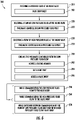
- Method 200 includes receiving a working fluid flow, e.g., the working fluid flow 28 (shown in FIG. 1 ), at the inline valve, as shown with box 210.
- Method 200 also includes receiving a flow of high pressure fluid, e.g. the flow of high pressure fluid 34 (shown in FIG. 1 ) at the inline valve, as shown with box 220.
- the method 200 additionally includes receiving a flow of low pressure fluid, e.g., the low pressure fluid 32 (shown in FIG. 1 ), at the inline valve, as shown with box 230.
- the flow of low pressure fluid be received at a low pressure port of the inline valve, e.g., the low pressure port 122 (shown in FIG. 2 )
- the flow of high pressure fluid be received at a high pressure port of the inline valve, e.g., the high pressure port 124 (shown in FIG. 2 )
- the working fluid flow be received at an inlet of the inline valve, e.g., the inlet 134 (shown in FIG. 2 ), as shown by boxes 212, 222, and 232.
- a portion of the low pressure fluid flows through a pneumatic controller of the inline valve, e.g., the controller 102 (shown in FIG. 2 ), cooling the pneumatic controller.
- the portion of the low pressure fluid flows across a biasing member supported within the pneumatic controller, e.g., the biasing member 120 (shown in FIG. 2 ), as shown with box 242, and out a vent port of the pneumatic controller, e.g., the vent port 128 (shown in FIG. 2 ) and into the ambient environment, as shown with box 244.
- the portion of the flow of low pressure fluid is directed by the vent port to a valve body of the inline valve, e.g., the valve body 104 (shown in FIG. 2 ).
- the portion of the low pressure fluid flows through the vent and cools the biasing member while low pressure fluid is communicated to the valve body of the inline valve.
- low pressure fluid flows through the vent and cools the biasing member while high pressure fluid communicated to the valve body of the inline valve.
- the biasing member can be cooled while switching between communication of the flow of low pressure fluid and the flow of high pressure fluid to the valve body.
- Inline valves can be operated by selectively applying muscle pressure for actuation of the inline valve using pneumatic controllers.
- controllers employing springs the air being controlled can be above the temperature at which the mechanical properties of the material forming the spring changes, potentially causing the spring performance to change and/or causing premature failure of the spring.
- pneumatic controllers having a high pressure port, a low pressure port, an actuator port, and a vent.
- the pneumatic controller connects the low pressure port or the high pressure port to the actuator port according to relative pressures of fluids received at the ports and the spring constant of a resilient member supported within the pneumatic controller, and cools the resilient member by flowing low pressure fluid received at the low pressure port across the resilient member and out the vent.
- This ensures that the resilient member remains insulated from heat by flow of low pressure fluid irrespective of the state of the valve, the resilient member remaining at a known temperature and within the temperature range of the material forming the resilient member, the resilient member thereby having more predictable spring characteristics than were ambient convective cooling employed.
- the present disclosure enables resilient members to be employed in environments which would otherwise be prohibitive due to the associated loadings and temperatures of the application. Further, cooling the resilient member with forced convection from a low pressure fluid source flowing across the resilient member and into the external environment allows temperature of the resilient member to be accurately predicted, reducing the tendency of such inaccuracy to result in resilient member performance and/or failures.
Landscapes
- Engineering & Computer Science (AREA)
- General Engineering & Computer Science (AREA)
- Mechanical Engineering (AREA)
- Physics & Mathematics (AREA)
- Fluid Mechanics (AREA)
- Chemical & Material Sciences (AREA)
- Combustion & Propulsion (AREA)
- Life Sciences & Earth Sciences (AREA)
- Sustainable Development (AREA)
- Fluid-Driven Valves (AREA)
Claims (15)
- Régulateur pneumatique pour une vanne en ligne, comprenant :un collecteur (116) ayant un orifice basse pression (122), un orifice haute pression (124), un orifice d'actionnement (126) et un évent (128) ;un sélecteur (118) mobile à l'intérieur du collecteur entre une première position et une seconde position, l'orifice basse pression étant en communication fluidique avec l'orifice d'actionnement dans la première position, l'orifice haute pression étant en communication fluidique avec l'orifice d'actionnement dans la seconde position ; etun élément de sollicitation (120) supporté à l'intérieur du collecteur et poussant le sélecteur vers la première position, caractérisé en ce quel'orifice basse pression est en communication fluidique avec l'évent à la fois dans la première position et la seconde position pour refroidir l'élément de sollicitation avec un fluide basse pression reçu au niveau de l'orifice basse pression.
- Régulateur pneumatique selon la revendication 1, dans lequel le collecteur comprend :un premier siège de sélecteur (180) fixé entre l'orifice haute pression et l'orifice d'actionnement ; etun second siège de sélecteur (182) fixé entre le premier siège de sélecteur et l'évent, dans lequel le sélecteur est disposé entre le premier siège de sélecteur et le second siège de sélecteur.
- Régulateur pneumatique selon la revendication 2, dans lequel l'élément de sollicitation est supporté à l'intérieur du collecteur entre le second siège de sélecteur et l'orifice basse pression ; ou
dans lequel l'élément de sollicitation est soutenu à l'intérieur du collecteur entre l'évent et l'orifice basse pression. - Régulateur pneumatique selon une quelconque revendication précédente, comprenant en outre un plongeur (166) supporté à l'intérieur du collecteur, le plongeur couplant l'élément de sollicitation au sélecteur.
- Régulateur pneumatique selon la revendication 4, dans lequel le plongeur chevauche l'évent le long de sa longueur ; et/ou
dans lequel le collecteur a un guide de plongeur (178) fixé entre le sélecteur et l'orifice basse pression, dans lequel le plongeur est disposé de manière coulissante à l'intérieur du guide de plongeur. - Régulateur pneumatique selon une quelconque revendication précédente, comprenant en outre un élément de siège (168) supporté à l'intérieur du collecteur, l'élément de siège étant agencé entre l'élément de sollicitation et l'orifice basse pression.
- Régulateur pneumatique selon la revendication 6 lorsqu'elle dépend de la revendication 4 ou de la revendication 5, dans lequel l'élément de siège a une partie de bride d'élément de siège, dans lequel l'élément de sollicitation est fixé à la partie de bride d'élément de siège ; et/ou
comprenant en outre le plongeur avec une partie de bride de plongeur (198), la partie de bride de plongeur étant agencée sur une extrémité du plongeur opposée au sélecteur, dans lequel l'élément de sollicitation est fixé à la partie de bride de plongeur. - Régulateur pneumatique selon une quelconque revendication précédente, dans lequel le collecteur a un canal de fluide connectant l'évent à chacun de l'orifice basse pression, de l'orifice haute pression et de l'orifice d'actionnement, dans lequel le sélecteur est disposé à l'intérieur du canal de fluide entre l'orifice haute pression et l'évent.
- Régulateur pneumatique selon une quelconque revendication précédente, comprenant en outre :un conduit pneumatique fixé à l'orifice d'actionnement ; etun corps de vanne ayant un extérieur et une chambre d'actionnement, la chambre d'actionnement étant connectée au conduit pneumatique, dans lequel le collecteur est fixé à l'extérieur du corps de vanne pour fournir un fluide basse pression ou un fluide haute pression à la chambre d'actionnement en fonction de la position du sélecteur.
- Régulateur pneumatique selon une quelconque revendication précédente, dans lequel le sélecteur a une forme sphérique, dans lequel le sélecteur comporte un matériau céramique.
- Régulateur pneumatique selon une quelconque revendication précédente, dans lequel le collecteur a une partie de montage, et comprenant en outre un corps de vanne avec un extérieur, la partie de montage connectant le collecteur au corps de vanne ; ou
dans lequel le collecteur a une partie de montage, dans lequel l'évent et la partie de montage se trouvent sur un côté commun du collecteur. - Vanne en ligne, comprenant :un régulateur pneumatique, selon la revendication 1, dans lequel le collecteur a une partie de montage ;un corps de vanne avec un extérieur, une entrée et une sortie, dans lequel la partie de montage du collecteur connecte le collecteur à l'extérieur du corps de vanne ; etun clapet (106) supporté à l'intérieur du corps de vanne et associé de manière opérationnelle au sélecteur, dans lequel le clapet est mobile entre un siège de clapet d'actionnement et un siège de clapet de corps de vanne à l'intérieur du corps de vanne, l'entrée du corps de vanne étant en communication fluidique avec la sortie du corps de vanne lorsque le clapet se trouve contre le siège de clapet d'actionnement, le clapet séparant fluidiquement l'entrée de la sortie lorsque le clapet se trouve contre le siège de clapet de corps de vanne.
- Vanne en ligne selon la revendication 12, dans laquelle l'évent s'oppose au corps de vanne pour délivrer un fluide basse pression reçu au niveau de l'orifice basse pression vers l'extérieur du corps de vanne ; et/ou
dans laquelle le régulateur pneumatique comprend :un premier siège de sélecteur agencé entre l'orifice haute pression et l'orifice d'actionnement ;un second siège de sélecteur agencé entre le premier siège de sélecteur et l'évent, dans laquelle le sélecteur est agencé entre le premier siège de sélecteur et le second siège de sélecteur ;un plongeur supporté à l'intérieur du collecteur, le plongeur couplant l'élément de sollicitation au sélecteur ; etun élément de siège supporté à l'intérieur du collecteur, l'élément de siège étant agencé entre l'élément de sollicitation et l'orifice basse pression. - Moteur à turbine à gaz, comprenant :un compresseur ayant un orifice de purge, un étage haute pression en aval de l'orifice de purge et un étage basse pression en amont de l'orifice de purge ;un régulateur pneumatique, selon revendication 1, dans lequel l'étage haute pression est connecté à l'orifice haute pression,dans lequel l'étage basse pression est connecté à l'orifice basse pression ; etune vanne en ligne avec un corps de vanne avec une entrée et une sortie, dans lequel l'entrée est en communication fluidique avec l'orifice de purge du compresseur, dans lequel le régulateur pneumatique est monté à l'extérieur du corps de vanne.
- Procédé de régulation de débit à travers une vanne en ligne, comprenant :au niveau d'un régulateur pneumatique comportant un collecteur ayant un orifice basse pression (122), un orifice haute pression (124), un orifice d'actionnement (126) et un évent (128) ; un sélecteur (118) mobile à l'intérieur du collecteur entre une première position et une seconde position, l'orifice basse pression étant en communication fluidique avec l'orifice d'actionnement dans la première position, l'orifice haute pression étant en communication fluidique avec l'orifice d'actionnement dans la seconde position ; et un élément de sollicitation (120) supporté à l'intérieur du collecteur etpousse le sélecteur vers la première position, dans lequel l'orifice basse pression est en communication fluidique avec l'évent à la fois dans la première position et la seconde position pour refroidir l'élément de sollicitation avec le fluide basse pression reçu au niveau de l'orifice basse pression ;la réception d'un fluide haute pression au niveau de l'orifice haute pression ;la réception d'un fluide basse pression au niveau de l'orifice basse pression ;la communication de l'un du fluide basse pression et du fluide haute pression à l'orifice d'actionnement en fonction de la position du sélecteur ; etle refroidissement de l'élément de sollicitation en faisant circuler le fluide basse pression à travers l'élément de sollicitation et à travers l'évent.
Applications Claiming Priority (1)
| Application Number | Priority Date | Filing Date | Title |
|---|---|---|---|
| US16/447,786 US10830372B1 (en) | 2019-06-20 | 2019-06-20 | Pneumatic controllers, pneumatically controlled inline valves, and methods of cooling pneumatic controllers |
Publications (2)
| Publication Number | Publication Date |
|---|---|
| EP3754231A1 EP3754231A1 (fr) | 2020-12-23 |
| EP3754231B1 true EP3754231B1 (fr) | 2022-04-27 |
Family
ID=68762573
Family Applications (1)
| Application Number | Title | Priority Date | Filing Date |
|---|---|---|---|
| EP19212831.2A Active EP3754231B1 (fr) | 2019-06-20 | 2019-12-02 | Régulateurs pneumatiques, vannes en ligne à commande pneumatique et procédés de refroidissement de régulateurs pneumatiques |
Country Status (2)
| Country | Link |
|---|---|
| US (1) | US10830372B1 (fr) |
| EP (1) | EP3754231B1 (fr) |
Families Citing this family (1)
| Publication number | Priority date | Publication date | Assignee | Title |
|---|---|---|---|---|
| FR3085709B1 (fr) * | 2018-09-06 | 2020-08-14 | Liebherr-Aerospace Toulouse Sas | Dispositif de refroidissement d'organes de commande sensibles a la chaleur d'une vanne pneumatique ou electropneumatique et vanne equipee d'un tel dispositif de refroidissement |
Family Cites Families (118)
| Publication number | Priority date | Publication date | Assignee | Title |
|---|---|---|---|---|
| US1362331A (en) * | 1919-03-06 | 1920-12-14 | Chester W Larner | Means for controlling valves |
| US1387446A (en) * | 1919-03-19 | 1921-08-16 | Astier Antoine Joseph | Valve for pipes for water and other fluids |
| US1829703A (en) * | 1919-07-22 | 1931-10-27 | Chester W Larner | Valve |
| US1441784A (en) * | 1920-06-03 | 1923-01-09 | Clayton James | Valve |
| US1448717A (en) * | 1921-02-09 | 1923-03-13 | Wellman Seaver Morgan Co | Valve |
| US1723736A (en) * | 1921-05-24 | 1929-08-06 | I P Morris Corp | Valve |
| US1841608A (en) * | 1925-12-07 | 1932-01-19 | I P Morris Corp | Check valve |
| US1824916A (en) * | 1926-11-17 | 1931-09-29 | Lewis F Moody | Valve |
| US1842146A (en) * | 1927-03-02 | 1932-01-19 | I P Morris & De La Vergne Inc | Valve for regulating the flow of fluids |
| US1777060A (en) * | 1927-03-12 | 1930-09-30 | Franklin G Neal | Valve |
| US1856222A (en) * | 1929-01-18 | 1932-05-03 | Universal Hydraulic Corp | Combined flow control and check valve |
| US1838723A (en) * | 1929-09-09 | 1931-12-29 | Franklin G Neal | Valve |
| US1941357A (en) * | 1930-03-18 | 1933-12-26 | I P Morris And De La Vergne In | Fluid control system |
| US2095410A (en) * | 1934-05-28 | 1937-10-12 | M L R Diescher | Combination stop and check valve |
| US2133983A (en) * | 1936-08-26 | 1938-10-25 | Audley D Gaston | Valve |
| US2085893A (en) * | 1936-12-11 | 1937-07-06 | Jerome A Boland | Valve |
| US2269671A (en) * | 1939-05-31 | 1942-01-13 | Phillip A Kinzie | Tube valve |
| US2442625A (en) * | 1943-12-16 | 1948-06-01 | Atomic Energy Commission | Packless valve |
| US2608204A (en) * | 1945-08-13 | 1952-08-26 | Stephen M Dunn | Valve |
| US2996074A (en) * | 1954-03-01 | 1961-08-15 | John S Page | Fluid pressure actuated shut-off valve |
| US2914079A (en) * | 1954-04-06 | 1959-11-24 | Western States Machine Co | Quick acting control valve for water driven centrifugal machines |
| US2931378A (en) * | 1955-01-14 | 1960-04-05 | Parker Hannifin Corp | Vented chamber, fluid pressure actuated valve |
| US2938533A (en) * | 1956-12-04 | 1960-05-31 | Garrett Corp | Shutoff valve |
| US3003516A (en) * | 1957-04-08 | 1961-10-10 | Granberg Corp | Flow control valve assembly |
| US2943636A (en) * | 1957-12-16 | 1960-07-05 | Phillips Petroleum Co | Fluid handling structure |
| US2919714A (en) * | 1958-01-03 | 1960-01-05 | United Aircraft Corp | Pressure balanced regulating and shut-off valve |
| US2950732A (en) * | 1958-09-11 | 1960-08-30 | Rotax Ltd | Compressed air or other gas control valves |
| US3076471A (en) * | 1959-05-25 | 1963-02-05 | Vapor Heating Corp | Modulating in-line valve |
| US3074685A (en) * | 1959-09-01 | 1963-01-22 | North American Aviation Inc | Anti-vibrating fluid control valve |
| US3092133A (en) * | 1959-11-09 | 1963-06-04 | Arkla Ind | Fluid regulating valve |
| GB1007138A (en) * | 1961-01-10 | 1965-10-13 | Plessey Co Ltd | Improvements in or relating to fluid flow control valves |
| US3092132A (en) * | 1961-05-15 | 1963-06-04 | Rotax Ltd | Compressed air or other gas control valves |
| US3172420A (en) * | 1961-05-18 | 1965-03-09 | Schulz Tool & Mfg Co | Liquid flow control system and by-pass valve |
| US3119405A (en) * | 1961-06-12 | 1964-01-28 | Rotax Ltd | Compressed air or other gas control valves |
| US3156253A (en) * | 1961-11-24 | 1964-11-10 | Gen Electric | Pressure regulating valve and combination on-off valve |
| US3177889A (en) * | 1961-12-04 | 1965-04-13 | Schulz Tool & Mfg Co | Float-operated surge relief shutoff valve |
| US3134394A (en) * | 1962-05-29 | 1964-05-26 | Ohta Tsunetaro | Check valves |
| US3194255A (en) * | 1962-07-09 | 1965-07-13 | Westinghouse Electric Corp | Check valve |
| US3192940A (en) * | 1963-01-07 | 1965-07-06 | Heil Co | Fluid control valves |
| US3338259A (en) * | 1964-01-24 | 1967-08-29 | Plessey Uk Ltd | Automatic regulating valves |
| US3297047A (en) * | 1964-03-17 | 1967-01-10 | Vapor Corp | Valve assembly |
| US3359998A (en) * | 1964-10-01 | 1967-12-26 | Donald G Griswold | Pressure control valves for fuel lines |
| US3380469A (en) * | 1965-07-16 | 1968-04-30 | Vapor Corp | Valve assembly |
| US3399689A (en) * | 1965-10-18 | 1968-09-03 | Victor Equipment Co | Control valve including independently operable pilot valves |
| US3490484A (en) * | 1968-03-07 | 1970-01-20 | Leslie A Runton | Valve for high pressure pipe lines |
| US3534769A (en) * | 1968-09-03 | 1970-10-20 | Treffle J Leveque | Valve for controlling speed and working pressure of air motors |
| US3489165A (en) * | 1968-10-30 | 1970-01-13 | Vapor Corp | Inline pressure regulator |
| US3583440A (en) * | 1968-11-26 | 1971-06-08 | Sven E Andersson | Automatic metering valve |
| US3566907A (en) * | 1969-04-25 | 1971-03-02 | Vapor Corp | Inline valve position indicator |
| US3586033A (en) * | 1969-07-07 | 1971-06-22 | Schulz Tool & Mfg Co | Combined aerial refueling coupling and pressure regulator |
| US3617151A (en) * | 1969-08-18 | 1971-11-02 | Drilling Well Control Inc | Fluid flow controlling valve and system |
| US3643707A (en) * | 1970-09-08 | 1972-02-22 | Cla Val Co | Static-reducing and vapor-reducing loading valve with low-pressure drop |
| US3643685A (en) * | 1970-11-04 | 1972-02-22 | Schaub Engineering Co | Flow regulator |
| US3945393A (en) * | 1972-02-29 | 1976-03-23 | Giuseppe Teatini | Regulating valve |
| GB1445081A (en) * | 1972-08-17 | 1976-08-04 | Lucas Industries Ltd | Pressure control valves |
| US3865128A (en) * | 1972-09-08 | 1975-02-11 | Vijay K Zadoo | Pressure regulating and shut-off valve |
| US3963044A (en) * | 1973-03-26 | 1976-06-15 | International Telephone And Telegraph Corporation | Pilot valve operated pressure regulator |
| US3792713A (en) * | 1973-05-21 | 1974-02-19 | Vapor Corp | Pressure regulator with flow limiter |
| US3825026A (en) * | 1973-06-01 | 1974-07-23 | Vapor Corp | Inline valve |
| US3792716A (en) * | 1973-06-13 | 1974-02-19 | Vapor Corp | Inline valve with reverse pressure closing means |
| US4077425A (en) * | 1973-06-14 | 1978-03-07 | Mordeki Drori | Fluid flow control devices |
| DE2428519A1 (de) * | 1974-06-12 | 1976-01-02 | Mokveld Mach Bv | Rueckschlagventil |
| US3987812A (en) * | 1975-11-10 | 1976-10-26 | Enterprise Brass Works | Adapter valve |
| US4052035A (en) * | 1975-11-20 | 1977-10-04 | Conservocon, Inc. | Remotely-controlled valve |
| DE2712307C2 (de) * | 1977-03-21 | 1982-04-22 | Klinger AG, 6301 Zug | Einrichtung zum Absperren zweier koaxialer Rohrleitungen |
| US4094334A (en) * | 1977-06-23 | 1978-06-13 | Taylor Julian S | Ocean thermal energy conversion valve |
| US4285495A (en) * | 1977-12-12 | 1981-08-25 | King Ottis W | Safety valve |
| US4226259A (en) * | 1978-11-13 | 1980-10-07 | Clemar Manufacturing Corp. | Regulator module |
| US4373544A (en) * | 1980-09-25 | 1983-02-15 | United Technologies Corporation | Check valve |
| US4479507A (en) * | 1981-06-29 | 1984-10-30 | Emerson Electric Co. | Fluid pressure operated valve |
| US4429709A (en) * | 1981-10-30 | 1984-02-07 | Niskanen Erkki J | Cascade-based method and device for fluid handling and measurement |
| US4565210A (en) * | 1984-09-11 | 1986-01-21 | R&H Technology, Inc. | Throttling and shut-off valve for slurry pipelines and the like |
| US4610265A (en) * | 1984-12-12 | 1986-09-09 | Sundstrand Corporation | Turbine compressor stall recovery valve |
| US4577654A (en) * | 1985-06-10 | 1986-03-25 | Camco, Incorporated | Fluid actuated pipeline valve |
| US4693268A (en) * | 1985-12-24 | 1987-09-15 | Dover Corporation | Poppet valve assembly and method of making same |
| US5005602A (en) * | 1985-12-24 | 1991-04-09 | Dover Corporation | Poppet valve assembly |
| US4732189A (en) * | 1986-05-06 | 1988-03-22 | The Secretary Of State For Defence In Her Britannic Majesty's Government Of The United Kingdom Of Great Britain And Northern Ireland | Fast opening valve |
| US5249599A (en) * | 1987-01-31 | 1993-10-05 | Haynes Joel E | Fluid flow regulator |
| EP0376115B1 (fr) | 1988-12-24 | 1992-08-05 | Barmag Ag | Valve hydraulique de sécurité |
| US4911196A (en) * | 1989-01-03 | 1990-03-27 | Kemp Development Corporation | Inline check valve |
| WO1992014083A1 (fr) | 1991-01-30 | 1992-08-20 | Memry Corp. | Soupape de securite |
| DE4236896A1 (de) * | 1992-10-31 | 1994-05-05 | Maury Hans Dietmar | Luftkanone zur Beseitigung von Schüttgutanbackungen und -stauungen |
| US5826613A (en) * | 1993-05-19 | 1998-10-27 | Georg Fischer Rohrleitungssysteme Ag | Flow control valve |
| US5540252A (en) * | 1994-07-21 | 1996-07-30 | United Technologies Corporation | Pneumatically stabilized inline valve |
| US5603352A (en) * | 1994-11-21 | 1997-02-18 | C. Valves Ltd. | Fluid flow control device including multiple valve units |
| US5921276A (en) * | 1995-10-17 | 1999-07-13 | Stream-Flo Industries, Ltd. | Piston-type check valve with diffuser |
| WO1997014898A1 (fr) * | 1995-10-19 | 1997-04-24 | C Valves Ltd. | Vanne de regulation en ligne |
| US5803356A (en) * | 1997-05-05 | 1998-09-08 | University Of British Columbia | Thermostat bypass system |
| IL128242A (en) * | 1999-01-26 | 2003-01-12 | Bermad Fa | Axial control valve |
| RU2159377C1 (ru) * | 1999-02-23 | 2000-11-20 | Открытое акционерное общество НПО Энергомаш им. акад. В.П. Глушко | Регулятор расхода |
| US6742539B2 (en) * | 2000-05-24 | 2004-06-01 | Innovative Controls | Co-axial control valve |
| US6446657B1 (en) * | 2000-12-15 | 2002-09-10 | Fairchild Controls Corporation | Aircraft air control valve apparatus |
| DE102004044818A1 (de) * | 2004-09-16 | 2006-03-23 | Robert Bosch Gmbh | Verdichterbypassventil bei mehrstufiger Aufladung |
| US7493912B2 (en) * | 2006-06-09 | 2009-02-24 | Hartman Brian T | Fixed cone sleeve valve having cone supported by means downstream of the gate in its closed position |
| US7775233B2 (en) * | 2007-03-15 | 2010-08-17 | Baker Hughes Incorporated | Choke or inline valve |
| JP5189399B2 (ja) * | 2008-04-07 | 2013-04-24 | 国立大学法人信州大学 | 逆止弁 |
| US8672289B2 (en) * | 2008-04-21 | 2014-03-18 | Pride Technologies International Pty Ltd | Domestic water tap or faucet with floating buoyant ball valve and activation rod |
| US8312893B2 (en) * | 2008-05-02 | 2012-11-20 | Control Components, Inc. | Axial drag valve with internal hub actuator |
| CN100554831C (zh) | 2008-07-17 | 2009-10-28 | 上海交通大学 | 跨临界二氧化碳制冷系统高压控制阀 |
| DE102008051759B3 (de) * | 2008-10-15 | 2010-04-29 | Karl Dungs Gmbh & Co. Kg | Rohrförmige Ventileinrichtung |
| US8136543B2 (en) * | 2009-01-27 | 2012-03-20 | Fisher Controls International, Llc | Axial flow control valves having an internal actuator |
| WO2010133902A2 (fr) * | 2009-05-20 | 2010-11-25 | Hydromat-Inzenjering D.O.O. | Vanne de régulation de piston axiale hydraulique et son application |
| US8656941B1 (en) * | 2010-01-11 | 2014-02-25 | Jansen's Aircraft System Controls, Inc. | Flow control valve |
| US9033306B2 (en) * | 2011-03-18 | 2015-05-19 | Gaither Tool Company, Inc. | Rapid opening gas valve |
| DE112013001096T5 (de) * | 2012-02-22 | 2014-11-06 | Magna Powertrain Of America, Inc. | Kegel-Kugelventil für geregelte Fluidströmungen |
| US8910653B2 (en) * | 2012-11-08 | 2014-12-16 | Hamilton Sundstrand Corporation | Valve assembly |
| US9080832B2 (en) * | 2013-05-09 | 2015-07-14 | Gaither Tool Company, Inc. | Quick-release valve air gun |
| US9689315B2 (en) | 2015-02-13 | 2017-06-27 | Hamilton Sundstrand Corporation | Full-area bleed valves |
| US20160376913A1 (en) * | 2015-06-29 | 2016-12-29 | Hamilton Sundstrand Corporation | Pressure limiters |
| CN205534367U (zh) | 2016-02-02 | 2016-08-31 | 成都欧迅科技股份有限公司 | 一种深海水下采油树阀组高稳态高压梭阀 |
| US10001026B2 (en) * | 2016-05-19 | 2018-06-19 | Hamilton Sunstrand Corporation | In-line shutoff valves |
| US10619569B2 (en) * | 2016-06-17 | 2020-04-14 | United Technologies Corporation | Gas turbine engine and method to cool a gas turbine engine case assembly |
| US10359123B2 (en) * | 2016-06-28 | 2019-07-23 | Eaton Intelligent Power Limited | Fluid pressure regulator with reverse flow capability |
| US10203040B2 (en) * | 2016-09-01 | 2019-02-12 | Raycon Industries, Inc. | Hydrant valve with internal shut-off valve |
| CA3082281A1 (fr) | 2017-11-21 | 2019-05-31 | Dukes Aerospace, Inc. | Systeme de soupape a clapet et procede |
| US10253901B1 (en) * | 2018-08-05 | 2019-04-09 | Electronics Inc. | Flow control valve with eddy current dampening |
| US10578215B2 (en) * | 2018-08-06 | 2020-03-03 | Hans D. Baumann | Inline high-recovery flow control valve |
| US10626802B2 (en) * | 2018-09-21 | 2020-04-21 | United Technologies Corporation | Ducted gas turbine engine stability bleed valve with passive and active shutoff |
-
2019
- 2019-06-20 US US16/447,786 patent/US10830372B1/en active Active
- 2019-12-02 EP EP19212831.2A patent/EP3754231B1/fr active Active
Also Published As
| Publication number | Publication date |
|---|---|
| EP3754231A1 (fr) | 2020-12-23 |
| US10830372B1 (en) | 2020-11-10 |
Similar Documents
| Publication | Publication Date | Title |
|---|---|---|
| US7784487B2 (en) | Fuel metering valve assembly including thermal compensation mechanism | |
| EP2423488A2 (fr) | Système de prélèvement d'air actionné par carburant | |
| EP3246607B1 (fr) | Vannes d'arrêt en ligne | |
| EP3045699B1 (fr) | Systèmes antigivrage | |
| EP3133297B1 (fr) | Moteur à turbine à gaz avec commande d'actionneur | |
| US10180106B2 (en) | Solenoids for gas turbine engine bleed valves | |
| US20170101937A1 (en) | Flow limiting duct vent valves and gas turbine engine bleed air systems including the same | |
| US10824172B1 (en) | Pneumatic controllers, pneumatically controlled inline valves, and methods of actuating inline valves | |
| EP3433519B1 (fr) | Compensation de pression d'entrée pour système de soupape | |
| EP3754231B1 (fr) | Régulateurs pneumatiques, vannes en ligne à commande pneumatique et procédés de refroidissement de régulateurs pneumatiques | |
| EP3118436B1 (fr) | Soupapes de purge pour moteurs à turbine à gaz | |
| US20190309762A1 (en) | Bleed valve with regulated opening | |
| US10823087B1 (en) | Inline valves, gas turbine engines with inline bleed valves, and methods controlling flow through inline valves | |
| US7669830B2 (en) | Three position shutoff valve | |
| US11168578B2 (en) | System for adjusting a variable position vane in an aircraft engine | |
| US11060454B2 (en) | Method of regulating air pressure in anti-icing system | |
| US11035372B2 (en) | Pneumatic controller for controlling a bleed valve | |
| US10823308B1 (en) | Controllers for inline valves, inline valves, and methods of controlling flow through inline valves | |
| CN112020622B (zh) | 具有多压力操作的阻尼止回阀 | |
| US11346356B2 (en) | Passive bleed valves with adjustable pressure threshold | |
| EP3604744B1 (fr) | Soupapes de purge en ligne passivement contrôlées | |
| US4391093A (en) | Temperature-responsive actuator | |
| EP3654129A1 (fr) | Surface de vanne partiellement circulaire pour vanne de cire | |
| US20200370480A1 (en) | Fueldraulic air valve |
Legal Events
| Date | Code | Title | Description |
|---|---|---|---|
| PUAI | Public reference made under article 153(3) epc to a published international application that has entered the european phase |
Free format text: ORIGINAL CODE: 0009012 |
|
| STAA | Information on the status of an ep patent application or granted ep patent |
Free format text: STATUS: THE APPLICATION HAS BEEN PUBLISHED |
|
| AK | Designated contracting states |
Kind code of ref document: A1 Designated state(s): AL AT BE BG CH CY CZ DE DK EE ES FI FR GB GR HR HU IE IS IT LI LT LU LV MC MK MT NL NO PL PT RO RS SE SI SK SM TR |
|
| AX | Request for extension of the european patent |
Extension state: BA ME |
|
| STAA | Information on the status of an ep patent application or granted ep patent |
Free format text: STATUS: REQUEST FOR EXAMINATION WAS MADE |
|
| 17P | Request for examination filed |
Effective date: 20210623 |
|
| RBV | Designated contracting states (corrected) |
Designated state(s): AL AT BE BG CH CY CZ DE DK EE ES FI FR GB GR HR HU IE IS IT LI LT LU LV MC MK MT NL NO PL PT RO RS SE SI SK SM TR |
|
| GRAP | Despatch of communication of intention to grant a patent |
Free format text: ORIGINAL CODE: EPIDOSNIGR1 |
|
| STAA | Information on the status of an ep patent application or granted ep patent |
Free format text: STATUS: GRANT OF PATENT IS INTENDED |
|
| RIC1 | Information provided on ipc code assigned before grant |
Ipc: F02C 9/52 20060101ALI20211029BHEP Ipc: F16K 49/00 20060101ALI20211029BHEP Ipc: F16K 11/056 20060101ALI20211029BHEP Ipc: F04D 27/02 20060101ALI20211029BHEP Ipc: F16K 11/044 20060101AFI20211029BHEP |
|
| INTG | Intention to grant announced |
Effective date: 20211124 |
|
| GRAS | Grant fee paid |
Free format text: ORIGINAL CODE: EPIDOSNIGR3 |
|
| GRAA | (expected) grant |
Free format text: ORIGINAL CODE: 0009210 |
|
| STAA | Information on the status of an ep patent application or granted ep patent |
Free format text: STATUS: THE PATENT HAS BEEN GRANTED |
|
| AK | Designated contracting states |
Kind code of ref document: B1 Designated state(s): AL AT BE BG CH CY CZ DE DK EE ES FI FR GB GR HR HU IE IS IT LI LT LU LV MC MK MT NL NO PL PT RO RS SE SI SK SM TR |
|
| REG | Reference to a national code |
Ref country code: GB Ref legal event code: FG4D |
|
| REG | Reference to a national code |
Ref country code: CH Ref legal event code: EP |
|
| REG | Reference to a national code |
Ref country code: AT Ref legal event code: REF Ref document number: 1487158 Country of ref document: AT Kind code of ref document: T Effective date: 20220515 |
|
| REG | Reference to a national code |
Ref country code: DE Ref legal event code: R096 Ref document number: 602019014109 Country of ref document: DE |
|
| REG | Reference to a national code |
Ref country code: IE Ref legal event code: FG4D |
|
| REG | Reference to a national code |
Ref country code: LT Ref legal event code: MG9D |
|
| REG | Reference to a national code |
Ref country code: NL Ref legal event code: MP Effective date: 20220427 |
|
| REG | Reference to a national code |
Ref country code: AT Ref legal event code: MK05 Ref document number: 1487158 Country of ref document: AT Kind code of ref document: T Effective date: 20220427 |
|
| PG25 | Lapsed in a contracting state [announced via postgrant information from national office to epo] |
Ref country code: NL Free format text: LAPSE BECAUSE OF FAILURE TO SUBMIT A TRANSLATION OF THE DESCRIPTION OR TO PAY THE FEE WITHIN THE PRESCRIBED TIME-LIMIT Effective date: 20220427 |
|
| PG25 | Lapsed in a contracting state [announced via postgrant information from national office to epo] |
Ref country code: SE Free format text: LAPSE BECAUSE OF FAILURE TO SUBMIT A TRANSLATION OF THE DESCRIPTION OR TO PAY THE FEE WITHIN THE PRESCRIBED TIME-LIMIT Effective date: 20220427 Ref country code: PT Free format text: LAPSE BECAUSE OF FAILURE TO SUBMIT A TRANSLATION OF THE DESCRIPTION OR TO PAY THE FEE WITHIN THE PRESCRIBED TIME-LIMIT Effective date: 20220829 Ref country code: NO Free format text: LAPSE BECAUSE OF FAILURE TO SUBMIT A TRANSLATION OF THE DESCRIPTION OR TO PAY THE FEE WITHIN THE PRESCRIBED TIME-LIMIT Effective date: 20220727 Ref country code: LT Free format text: LAPSE BECAUSE OF FAILURE TO SUBMIT A TRANSLATION OF THE DESCRIPTION OR TO PAY THE FEE WITHIN THE PRESCRIBED TIME-LIMIT Effective date: 20220427 Ref country code: HR Free format text: LAPSE BECAUSE OF FAILURE TO SUBMIT A TRANSLATION OF THE DESCRIPTION OR TO PAY THE FEE WITHIN THE PRESCRIBED TIME-LIMIT Effective date: 20220427 Ref country code: GR Free format text: LAPSE BECAUSE OF FAILURE TO SUBMIT A TRANSLATION OF THE DESCRIPTION OR TO PAY THE FEE WITHIN THE PRESCRIBED TIME-LIMIT Effective date: 20220728 Ref country code: FI Free format text: LAPSE BECAUSE OF FAILURE TO SUBMIT A TRANSLATION OF THE DESCRIPTION OR TO PAY THE FEE WITHIN THE PRESCRIBED TIME-LIMIT Effective date: 20220427 Ref country code: BG Free format text: LAPSE BECAUSE OF FAILURE TO SUBMIT A TRANSLATION OF THE DESCRIPTION OR TO PAY THE FEE WITHIN THE PRESCRIBED TIME-LIMIT Effective date: 20220727 Ref country code: AT Free format text: LAPSE BECAUSE OF FAILURE TO SUBMIT A TRANSLATION OF THE DESCRIPTION OR TO PAY THE FEE WITHIN THE PRESCRIBED TIME-LIMIT Effective date: 20220427 |
|
| PG25 | Lapsed in a contracting state [announced via postgrant information from national office to epo] |
Ref country code: RS Free format text: LAPSE BECAUSE OF FAILURE TO SUBMIT A TRANSLATION OF THE DESCRIPTION OR TO PAY THE FEE WITHIN THE PRESCRIBED TIME-LIMIT Effective date: 20220427 Ref country code: PL Free format text: LAPSE BECAUSE OF FAILURE TO SUBMIT A TRANSLATION OF THE DESCRIPTION OR TO PAY THE FEE WITHIN THE PRESCRIBED TIME-LIMIT Effective date: 20220427 Ref country code: LV Free format text: LAPSE BECAUSE OF FAILURE TO SUBMIT A TRANSLATION OF THE DESCRIPTION OR TO PAY THE FEE WITHIN THE PRESCRIBED TIME-LIMIT Effective date: 20220427 Ref country code: IS Free format text: LAPSE BECAUSE OF FAILURE TO SUBMIT A TRANSLATION OF THE DESCRIPTION OR TO PAY THE FEE WITHIN THE PRESCRIBED TIME-LIMIT Effective date: 20220827 |
|
| REG | Reference to a national code |
Ref country code: DE Ref legal event code: R097 Ref document number: 602019014109 Country of ref document: DE |
|
| PG25 | Lapsed in a contracting state [announced via postgrant information from national office to epo] |
Ref country code: SM Free format text: LAPSE BECAUSE OF FAILURE TO SUBMIT A TRANSLATION OF THE DESCRIPTION OR TO PAY THE FEE WITHIN THE PRESCRIBED TIME-LIMIT Effective date: 20220427 Ref country code: SK Free format text: LAPSE BECAUSE OF FAILURE TO SUBMIT A TRANSLATION OF THE DESCRIPTION OR TO PAY THE FEE WITHIN THE PRESCRIBED TIME-LIMIT Effective date: 20220427 Ref country code: RO Free format text: LAPSE BECAUSE OF FAILURE TO SUBMIT A TRANSLATION OF THE DESCRIPTION OR TO PAY THE FEE WITHIN THE PRESCRIBED TIME-LIMIT Effective date: 20220427 Ref country code: ES Free format text: LAPSE BECAUSE OF FAILURE TO SUBMIT A TRANSLATION OF THE DESCRIPTION OR TO PAY THE FEE WITHIN THE PRESCRIBED TIME-LIMIT Effective date: 20220427 Ref country code: EE Free format text: LAPSE BECAUSE OF FAILURE TO SUBMIT A TRANSLATION OF THE DESCRIPTION OR TO PAY THE FEE WITHIN THE PRESCRIBED TIME-LIMIT Effective date: 20220427 Ref country code: DK Free format text: LAPSE BECAUSE OF FAILURE TO SUBMIT A TRANSLATION OF THE DESCRIPTION OR TO PAY THE FEE WITHIN THE PRESCRIBED TIME-LIMIT Effective date: 20220427 Ref country code: CZ Free format text: LAPSE BECAUSE OF FAILURE TO SUBMIT A TRANSLATION OF THE DESCRIPTION OR TO PAY THE FEE WITHIN THE PRESCRIBED TIME-LIMIT Effective date: 20220427 |
|
| PLBE | No opposition filed within time limit |
Free format text: ORIGINAL CODE: 0009261 |
|
| STAA | Information on the status of an ep patent application or granted ep patent |
Free format text: STATUS: NO OPPOSITION FILED WITHIN TIME LIMIT |
|
| PG25 | Lapsed in a contracting state [announced via postgrant information from national office to epo] |
Ref country code: AL Free format text: LAPSE BECAUSE OF FAILURE TO SUBMIT A TRANSLATION OF THE DESCRIPTION OR TO PAY THE FEE WITHIN THE PRESCRIBED TIME-LIMIT Effective date: 20220427 |
|
| 26N | No opposition filed |
Effective date: 20230130 |
|
| PG25 | Lapsed in a contracting state [announced via postgrant information from national office to epo] |
Ref country code: SI Free format text: LAPSE BECAUSE OF FAILURE TO SUBMIT A TRANSLATION OF THE DESCRIPTION OR TO PAY THE FEE WITHIN THE PRESCRIBED TIME-LIMIT Effective date: 20220427 |
|
| P01 | Opt-out of the competence of the unified patent court (upc) registered |
Effective date: 20230603 |
|
| REG | Reference to a national code |
Ref country code: CH Ref legal event code: PL |
|
| REG | Reference to a national code |
Ref country code: BE Ref legal event code: MM Effective date: 20221231 |
|
| PG25 | Lapsed in a contracting state [announced via postgrant information from national office to epo] |
Ref country code: LU Free format text: LAPSE BECAUSE OF NON-PAYMENT OF DUE FEES Effective date: 20221202 |
|
| PG25 | Lapsed in a contracting state [announced via postgrant information from national office to epo] |
Ref country code: LI Free format text: LAPSE BECAUSE OF NON-PAYMENT OF DUE FEES Effective date: 20221231 Ref country code: IE Free format text: LAPSE BECAUSE OF NON-PAYMENT OF DUE FEES Effective date: 20221202 Ref country code: CH Free format text: LAPSE BECAUSE OF NON-PAYMENT OF DUE FEES Effective date: 20221231 |
|
| PG25 | Lapsed in a contracting state [announced via postgrant information from national office to epo] |
Ref country code: BE Free format text: LAPSE BECAUSE OF NON-PAYMENT OF DUE FEES Effective date: 20221231 |
|
| PGFP | Annual fee paid to national office [announced via postgrant information from national office to epo] |
Ref country code: GB Payment date: 20231124 Year of fee payment: 5 |
|
| PG25 | Lapsed in a contracting state [announced via postgrant information from national office to epo] |
Ref country code: IT Free format text: LAPSE BECAUSE OF FAILURE TO SUBMIT A TRANSLATION OF THE DESCRIPTION OR TO PAY THE FEE WITHIN THE PRESCRIBED TIME-LIMIT Effective date: 20220427 |
|
| PGFP | Annual fee paid to national office [announced via postgrant information from national office to epo] |
Ref country code: FR Payment date: 20231122 Year of fee payment: 5 Ref country code: DE Payment date: 20231121 Year of fee payment: 5 |
|
| PG25 | Lapsed in a contracting state [announced via postgrant information from national office to epo] |
Ref country code: CY Free format text: LAPSE BECAUSE OF FAILURE TO SUBMIT A TRANSLATION OF THE DESCRIPTION OR TO PAY THE FEE WITHIN THE PRESCRIBED TIME-LIMIT Effective date: 20220427 |
|
| PG25 | Lapsed in a contracting state [announced via postgrant information from national office to epo] |
Ref country code: MK Free format text: LAPSE BECAUSE OF FAILURE TO SUBMIT A TRANSLATION OF THE DESCRIPTION OR TO PAY THE FEE WITHIN THE PRESCRIBED TIME-LIMIT Effective date: 20220427 Ref country code: HU Free format text: LAPSE BECAUSE OF FAILURE TO SUBMIT A TRANSLATION OF THE DESCRIPTION OR TO PAY THE FEE WITHIN THE PRESCRIBED TIME-LIMIT; INVALID AB INITIO Effective date: 20191202 |
|
| PG25 | Lapsed in a contracting state [announced via postgrant information from national office to epo] |
Ref country code: MC Free format text: LAPSE BECAUSE OF FAILURE TO SUBMIT A TRANSLATION OF THE DESCRIPTION OR TO PAY THE FEE WITHIN THE PRESCRIBED TIME-LIMIT Effective date: 20220427 |
|
| PG25 | Lapsed in a contracting state [announced via postgrant information from national office to epo] |
Ref country code: MC Free format text: LAPSE BECAUSE OF FAILURE TO SUBMIT A TRANSLATION OF THE DESCRIPTION OR TO PAY THE FEE WITHIN THE PRESCRIBED TIME-LIMIT Effective date: 20220427 |