EP3754205A1 - Air blowing device and air conditioning device - Google Patents
Air blowing device and air conditioning device Download PDFInfo
- Publication number
- EP3754205A1 EP3754205A1 EP19757862.8A EP19757862A EP3754205A1 EP 3754205 A1 EP3754205 A1 EP 3754205A1 EP 19757862 A EP19757862 A EP 19757862A EP 3754205 A1 EP3754205 A1 EP 3754205A1
- Authority
- EP
- European Patent Office
- Prior art keywords
- air
- virtual plane
- blow
- out region
- wind velocity
- Prior art date
- Legal status (The legal status is an assumption and is not a legal conclusion. Google has not performed a legal analysis and makes no representation as to the accuracy of the status listed.)
- Withdrawn
Links
- 238000007664 blowing Methods 0.000 title claims abstract description 126
- 238000004378 air conditioning Methods 0.000 title 1
- 238000011144 upstream manufacturing Methods 0.000 claims description 3
- 239000011159 matrix material Substances 0.000 description 5
- 230000005484 gravity Effects 0.000 description 4
- 239000003507 refrigerant Substances 0.000 description 3
- 238000004891 communication Methods 0.000 description 2
- 238000009434 installation Methods 0.000 description 2
- 238000005259 measurement Methods 0.000 description 2
- 238000012935 Averaging Methods 0.000 description 1
- 230000007423 decrease Effects 0.000 description 1
- 238000010586 diagram Methods 0.000 description 1
- 230000006870 function Effects 0.000 description 1
- 230000001771 impaired effect Effects 0.000 description 1
- 230000001939 inductive effect Effects 0.000 description 1
- 238000012986 modification Methods 0.000 description 1
- 230000004048 modification Effects 0.000 description 1
- 239000004745 nonwoven fabric Substances 0.000 description 1
- 238000004080 punching Methods 0.000 description 1
- 238000005057 refrigeration Methods 0.000 description 1
Images




Classifications
-
- F—MECHANICAL ENGINEERING; LIGHTING; HEATING; WEAPONS; BLASTING
- F04—POSITIVE - DISPLACEMENT MACHINES FOR LIQUIDS; PUMPS FOR LIQUIDS OR ELASTIC FLUIDS
- F04D—NON-POSITIVE-DISPLACEMENT PUMPS
- F04D25/00—Pumping installations or systems
- F04D25/16—Combinations of two or more pumps ; Producing two or more separate gas flows
- F04D25/166—Combinations of two or more pumps ; Producing two or more separate gas flows using fans
-
- F—MECHANICAL ENGINEERING; LIGHTING; HEATING; WEAPONS; BLASTING
- F04—POSITIVE - DISPLACEMENT MACHINES FOR LIQUIDS; PUMPS FOR LIQUIDS OR ELASTIC FLUIDS
- F04D—NON-POSITIVE-DISPLACEMENT PUMPS
- F04D25/00—Pumping installations or systems
- F04D25/02—Units comprising pumps and their driving means
- F04D25/08—Units comprising pumps and their driving means the working fluid being air, e.g. for ventilation
-
- F—MECHANICAL ENGINEERING; LIGHTING; HEATING; WEAPONS; BLASTING
- F04—POSITIVE - DISPLACEMENT MACHINES FOR LIQUIDS; PUMPS FOR LIQUIDS OR ELASTIC FLUIDS
- F04D—NON-POSITIVE-DISPLACEMENT PUMPS
- F04D25/00—Pumping installations or systems
- F04D25/16—Combinations of two or more pumps ; Producing two or more separate gas flows
-
- F—MECHANICAL ENGINEERING; LIGHTING; HEATING; WEAPONS; BLASTING
- F04—POSITIVE - DISPLACEMENT MACHINES FOR LIQUIDS; PUMPS FOR LIQUIDS OR ELASTIC FLUIDS
- F04D—NON-POSITIVE-DISPLACEMENT PUMPS
- F04D27/00—Control, e.g. regulation, of pumps, pumping installations or pumping systems specially adapted for elastic fluids
- F04D27/004—Control, e.g. regulation, of pumps, pumping installations or pumping systems specially adapted for elastic fluids by varying driving speed
-
- F—MECHANICAL ENGINEERING; LIGHTING; HEATING; WEAPONS; BLASTING
- F04—POSITIVE - DISPLACEMENT MACHINES FOR LIQUIDS; PUMPS FOR LIQUIDS OR ELASTIC FLUIDS
- F04D—NON-POSITIVE-DISPLACEMENT PUMPS
- F04D29/00—Details, component parts, or accessories
- F04D29/40—Casings; Connections of working fluid
- F04D29/42—Casings; Connections of working fluid for radial or helico-centrifugal pumps
- F04D29/44—Fluid-guiding means, e.g. diffusers
- F04D29/441—Fluid-guiding means, e.g. diffusers especially adapted for elastic fluid pumps
-
- F—MECHANICAL ENGINEERING; LIGHTING; HEATING; WEAPONS; BLASTING
- F04—POSITIVE - DISPLACEMENT MACHINES FOR LIQUIDS; PUMPS FOR LIQUIDS OR ELASTIC FLUIDS
- F04D—NON-POSITIVE-DISPLACEMENT PUMPS
- F04D29/00—Details, component parts, or accessories
- F04D29/40—Casings; Connections of working fluid
- F04D29/52—Casings; Connections of working fluid for axial pumps
- F04D29/54—Fluid-guiding means, e.g. diffusers
- F04D29/541—Specially adapted for elastic fluid pumps
-
- F—MECHANICAL ENGINEERING; LIGHTING; HEATING; WEAPONS; BLASTING
- F04—POSITIVE - DISPLACEMENT MACHINES FOR LIQUIDS; PUMPS FOR LIQUIDS OR ELASTIC FLUIDS
- F04D—NON-POSITIVE-DISPLACEMENT PUMPS
- F04D29/00—Details, component parts, or accessories
- F04D29/40—Casings; Connections of working fluid
- F04D29/52—Casings; Connections of working fluid for axial pumps
- F04D29/54—Fluid-guiding means, e.g. diffusers
- F04D29/541—Specially adapted for elastic fluid pumps
- F04D29/545—Ducts
-
- F—MECHANICAL ENGINEERING; LIGHTING; HEATING; WEAPONS; BLASTING
- F04—POSITIVE - DISPLACEMENT MACHINES FOR LIQUIDS; PUMPS FOR LIQUIDS OR ELASTIC FLUIDS
- F04D—NON-POSITIVE-DISPLACEMENT PUMPS
- F04D29/00—Details, component parts, or accessories
- F04D29/40—Casings; Connections of working fluid
- F04D29/52—Casings; Connections of working fluid for axial pumps
- F04D29/54—Fluid-guiding means, e.g. diffusers
- F04D29/56—Fluid-guiding means, e.g. diffusers adjustable
-
- F—MECHANICAL ENGINEERING; LIGHTING; HEATING; WEAPONS; BLASTING
- F04—POSITIVE - DISPLACEMENT MACHINES FOR LIQUIDS; PUMPS FOR LIQUIDS OR ELASTIC FLUIDS
- F04D—NON-POSITIVE-DISPLACEMENT PUMPS
- F04D29/00—Details, component parts, or accessories
- F04D29/58—Cooling; Heating; Diminishing heat transfer
-
- F—MECHANICAL ENGINEERING; LIGHTING; HEATING; WEAPONS; BLASTING
- F04—POSITIVE - DISPLACEMENT MACHINES FOR LIQUIDS; PUMPS FOR LIQUIDS OR ELASTIC FLUIDS
- F04D—NON-POSITIVE-DISPLACEMENT PUMPS
- F04D29/00—Details, component parts, or accessories
- F04D29/70—Suction grids; Strainers; Dust separation; Cleaning
- F04D29/701—Suction grids; Strainers; Dust separation; Cleaning especially adapted for elastic fluid pumps
- F04D29/703—Suction grids; Strainers; Dust separation; Cleaning especially adapted for elastic fluid pumps specially for fans, e.g. fan guards
-
- F—MECHANICAL ENGINEERING; LIGHTING; HEATING; WEAPONS; BLASTING
- F24—HEATING; RANGES; VENTILATING
- F24F—AIR-CONDITIONING; AIR-HUMIDIFICATION; VENTILATION; USE OF AIR CURRENTS FOR SCREENING
- F24F1/00—Room units for air-conditioning, e.g. separate or self-contained units or units receiving primary air from a central station
- F24F1/0007—Indoor units, e.g. fan coil units
- F24F1/0018—Indoor units, e.g. fan coil units characterised by fans
- F24F1/0029—Axial fans
-
- F—MECHANICAL ENGINEERING; LIGHTING; HEATING; WEAPONS; BLASTING
- F24—HEATING; RANGES; VENTILATING
- F24F—AIR-CONDITIONING; AIR-HUMIDIFICATION; VENTILATION; USE OF AIR CURRENTS FOR SCREENING
- F24F1/00—Room units for air-conditioning, e.g. separate or self-contained units or units receiving primary air from a central station
- F24F1/0007—Indoor units, e.g. fan coil units
- F24F1/0059—Indoor units, e.g. fan coil units characterised by heat exchangers
- F24F1/0063—Indoor units, e.g. fan coil units characterised by heat exchangers by the mounting or arrangement of the heat exchangers
-
- F—MECHANICAL ENGINEERING; LIGHTING; HEATING; WEAPONS; BLASTING
- F24—HEATING; RANGES; VENTILATING
- F24F—AIR-CONDITIONING; AIR-HUMIDIFICATION; VENTILATION; USE OF AIR CURRENTS FOR SCREENING
- F24F11/00—Control or safety arrangements
- F24F11/70—Control systems characterised by their outputs; Constructional details thereof
- F24F11/72—Control systems characterised by their outputs; Constructional details thereof for controlling the supply of treated air, e.g. its pressure
- F24F11/74—Control systems characterised by their outputs; Constructional details thereof for controlling the supply of treated air, e.g. its pressure for controlling air flow rate or air velocity
-
- F—MECHANICAL ENGINEERING; LIGHTING; HEATING; WEAPONS; BLASTING
- F24—HEATING; RANGES; VENTILATING
- F24F—AIR-CONDITIONING; AIR-HUMIDIFICATION; VENTILATION; USE OF AIR CURRENTS FOR SCREENING
- F24F11/00—Control or safety arrangements
- F24F11/70—Control systems characterised by their outputs; Constructional details thereof
- F24F11/72—Control systems characterised by their outputs; Constructional details thereof for controlling the supply of treated air, e.g. its pressure
- F24F11/74—Control systems characterised by their outputs; Constructional details thereof for controlling the supply of treated air, e.g. its pressure for controlling air flow rate or air velocity
- F24F11/77—Control systems characterised by their outputs; Constructional details thereof for controlling the supply of treated air, e.g. its pressure for controlling air flow rate or air velocity by controlling the speed of ventilators
-
- F—MECHANICAL ENGINEERING; LIGHTING; HEATING; WEAPONS; BLASTING
- F24—HEATING; RANGES; VENTILATING
- F24F—AIR-CONDITIONING; AIR-HUMIDIFICATION; VENTILATION; USE OF AIR CURRENTS FOR SCREENING
- F24F7/00—Ventilation
- F24F7/007—Ventilation with forced flow
-
- F—MECHANICAL ENGINEERING; LIGHTING; HEATING; WEAPONS; BLASTING
- F05—INDEXING SCHEMES RELATING TO ENGINES OR PUMPS IN VARIOUS SUBCLASSES OF CLASSES F01-F04
- F05D—INDEXING SCHEME FOR ASPECTS RELATING TO NON-POSITIVE-DISPLACEMENT MACHINES OR ENGINES, GAS-TURBINES OR JET-PROPULSION PLANTS
- F05D2210/00—Working fluids
- F05D2210/10—Kind or type
- F05D2210/12—Kind or type gaseous, i.e. compressible
-
- F—MECHANICAL ENGINEERING; LIGHTING; HEATING; WEAPONS; BLASTING
- F24—HEATING; RANGES; VENTILATING
- F24F—AIR-CONDITIONING; AIR-HUMIDIFICATION; VENTILATION; USE OF AIR CURRENTS FOR SCREENING
- F24F13/00—Details common to, or for air-conditioning, air-humidification, ventilation or use of air currents for screening
- F24F13/08—Air-flow control members, e.g. louvres, grilles, flaps or guide plates
-
- F—MECHANICAL ENGINEERING; LIGHTING; HEATING; WEAPONS; BLASTING
- F24—HEATING; RANGES; VENTILATING
- F24F—AIR-CONDITIONING; AIR-HUMIDIFICATION; VENTILATION; USE OF AIR CURRENTS FOR SCREENING
- F24F2110/00—Control inputs relating to air properties
- F24F2110/30—Velocity
-
- Y—GENERAL TAGGING OF NEW TECHNOLOGICAL DEVELOPMENTS; GENERAL TAGGING OF CROSS-SECTIONAL TECHNOLOGIES SPANNING OVER SEVERAL SECTIONS OF THE IPC; TECHNICAL SUBJECTS COVERED BY FORMER USPC CROSS-REFERENCE ART COLLECTIONS [XRACs] AND DIGESTS
- Y02—TECHNOLOGIES OR APPLICATIONS FOR MITIGATION OR ADAPTATION AGAINST CLIMATE CHANGE
- Y02B—CLIMATE CHANGE MITIGATION TECHNOLOGIES RELATED TO BUILDINGS, e.g. HOUSING, HOUSE APPLIANCES OR RELATED END-USER APPLICATIONS
- Y02B30/00—Energy efficient heating, ventilation or air conditioning [HVAC]
- Y02B30/70—Efficient control or regulation technologies, e.g. for control of refrigerant flow, motor or heating
Definitions
- the present disclosure relates to an air-blowing apparatus and an air conditioner including the air-blowing apparatus.
- Patent Document 1 discloses an air-blowing apparatus including a plurality of axial blowers.
- the air-blowing apparatus utilizes an inducing action by an air current blown out from the blowers to obtain a relatively large air-blowing volume.
- Patent Document 1 Japanese Unexamined Patent Publication No. 2016-089734
- Wind naturally wind blowing outdoors in a natural environment has a relatively small difference in velocity in different parts of a region whose area is about a frontal projection area of a typical adult man (approximately, 0.6 square meters). For this reason, natural wind has a relatively small difference in the velocity when blowing against different parts of the body of a person exposed to the wind.
- a conventional air-blowing apparatus such as that disclosed in Patent Document 1 is configured in consideration of obtaining a large air-blowing volume and increasing wind velocity to extend a reaching distance of an air current.
- This means that in a conventional air-blowing apparatus not much of an emphasis has been put on averaging wind velocity distribution in a relatively large region.
- a conventional air-blowing apparatus usually blows wind which has a relatively large difference in velocity when blowing against different parts of the body of a person exposed to the wind.
- the conventional air-blowing apparatus has not been able to provide a person with comfort similar to that when the person is exposed to natural wind.
- An object of the present disclosure is to improve comfort of a person exposed to the wind blowing from an air-blowing apparatus.
- a first aspect of the present disclosure is directed to an air-blowing apparatus including: a main body (15) in which a blow-out region (16) for blowing out air is formed; and a blowing member (30) provided in the main body (15) and configured to send the air toward the blow-out region (16), wherein in a case in which a rectangular virtual plane that faces the blow-out region (16), is positioned at a distance of 1 m from the blow-out region (16), and has a long side extending in a vertical direction and having a length of 60 cm and a short side extending in a right-to-left direction and having a length of 45 cm is set as a front virtual plane (65), a rectangular virtual plane that faces the blow-out region (16), is positioned at a distance of 3 m from the blow-out region (16), and has a long side extending in the vertical direction and having a length of 180 cm and a short side extending in the right-to-left direction and having a length of 90 cm is set as a rear virtual plane (67
- the airflow generated by the blowing member (30) is sent out from the blow-out region (16) toward the target virtual plane (61).
- the ratio (Vmax/Vmin) of the maximum value Vmax to the minimum value Vmin of the wind velocity is 1 or more and 10 or less in each portion of the target virtual plane (61). For this reason, wind blown out from the blow-out region (16) has a relatively small difference in velocity when blowing against different parts of the body of a person exposed to the wind. Therefore, according to this aspect, comfort of the person exposed to the wind from the air-blowing apparatus (10) may be improved.
- a second aspect of the present disclosure is an embodiment of the first aspect.
- air is blown out from the blow-out region (16) such that a ratio (Vmax/Vmin) of a maximum value Vmax of wind velocity to a minimum value Vmin of the wind velocity is 1 or more and 5 or less in the target virtual plane (61).
- the ratio (Vmax/Vmin) of the maximum value to the minimum value of wind velocity is 1 or more and 5 or less is each portion of the target virtual plane (61).
- a third aspect of the present disclosure is an embodiment of the first aspect.
- air is blown out from the blow-out region (16) such that a ratio (Vmax/Vmin) of a maximum value Vmax of wind velocity to a minimum value Vmin of the wind velocity is 1 or more and 2.5 or less in the target virtual plane (61).
- the ratio (Vmax/Vmin) of the maximum value to the minimum value of wind velocity is 1 or more and 2.5 or less is each portion of the target virtual plane (61).
- a fourth aspect of the present disclosure is an embodiment of any one of the first to third aspects.
- a rectangular virtual plane that faces the blow-out region (16) is positioned at a distance of 2 m from the blow-out region (16), and has a long side extending in the vertical direction and having a length of 120 cm and a short side extending in the right-to-left direction and having a length of 67.5 cm is set as a middle virtual plane (66)
- the target virtual plane (61) is located in a portion of the target virtual space (60) between the front virtual plane (65) and the middle virtual plane (66).
- At least one of the virtual planes included in the target virtual space (60) between the front virtual plane (65) and the middle virtual plane (66), and parallel to the front virtual plane (65) is set as a target virtual plane (61).
- a fifth aspect of the present disclosure is an embodiment of any one of the first to third aspects.
- the target virtual plane (61) is the rear virtual plane (67).
- the rear virtual plane (67) is the target virtual plane (61).
- the ratio (Vmax/Vmin) of the maximum value to the minimum value of wind velocity is within a predetermined value range in each portion of the rear virtual plane (67).
- a sixth aspect of the present disclosure is an embodiment of any one of the first to fifth aspects.
- the blowing member is a plurality of fans (30) arranged so as to face the blow-out region (16).
- the plurality of fans (30) are provided as the blowing members (30) in the air-blowing apparatus (10). When the fans (30) are operating, air is blown out from the blow-out region (16) of the main body (15).
- a seventh aspect of the present disclosure is an embodiment of any one of the first to fifth aspects.
- the main body (15) includes a rectifying member (17) configured to allow air to pass therethrough and provided on the entire blow-out region (16), and the blowing member (30) is a fan (30) arranged upstream of the rectifying member (17).
- the fan (30) is provided as the blowing member (30) in the air-blowing apparatus (10).
- the air blown out from the fan (30) is rectified when passing through the rectifying member (17), and then blown out from the blow-out region (16).
- the air-blowing apparatus (10) further includes a controller (40) which controls operation of the blowing member (30), based on wind velocity data including a fluctuation pattern of wind velocity of outdoor natural wind obtained in advance or in real time, such that a fluctuation pattern of a flow rate of the air blown out from the blow-out region (16) is the fluctuation pattern of the wind velocity included in the wind velocity data.
- the controller (40) controls the operation of the blowing member (30) such that the fluctuation pattern of the flow rate of air blown out from the blow-out region (16) is a fluctuation pattern of wind velocity included in the wind velocity data (that is, a fluctuation pattern of the wind velocity of outdoor natural wind).
- the fluctuation pattern of the wind velocity of natural wind included in the wind velocity data may be reproduced by the air-blowing apparatus (10).
- a ninth aspect of the present disclosure is directed to an air conditioner including: the air-blowing apparatus (10) of any one of the first to eighth aspects; and a heat exchanger (55) which allows heat exchange of supply air to be sucked into the air-blowing apparatus (10) with a thermal medium to adjust a temperature of the supply air.
- the air-blowing apparatus (10) includes a main body (15).
- the main body (15) is formed in a rectangular parallelepiped shape having a relatively short depth in a front-rear direction.
- the main body (15) has a width in a right-to-left direction and a height in a vertical direction, each of approximately 1.6 m. Note that “upper”, “lower”, “left”, “right”, “front”, and “rear” used in the description of the main body (15) refer to the directions shown in FIG. 2 (i.e., the directions when the main body (15) is viewed from the front).
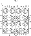
- the main body (15) is provided with sixteen fans (30) as blowing members.
- the sixteen fans (30) are arranged in matrix, four in the right-to-left direction and four in a vertical direction.
- Each fan (30) is an axial blower including an impeller (31) and a shroud (32).
- the impeller (31) is a so-called propeller fan.
- the shroud (32) is arranged in each fan (30) to surround the circumference of the impeller (31).
- each fan (30) is provided with a fan motor for driving the impeller (31).
- the impeller (31) is attached to an output shaft of the fan motor.
- the sixteen fans (30) face onto the front surface of the main body (15).
- the front surface of the main body (15) constitutes a blow-out region (16) from which the air that has been blown out from each fan (30) is blown out.
- the blow-out region (16) is a square plane having a width of 1.6 m in the right-to-left direction and a height of 1.6 m in the vertical direction.
- the air-blowing apparatus (10) further includes a controller (40).
- the controller (40) includes a CPU that executes a control program, and a memory that stores the control program, data necessary for executing the control program, and the like.
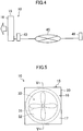
- the controller (40) is communicably connected to a sensor unit (46) installed outdoors at a remote location via a communication line (45) such as the Internet.
- the sensor unit (46) includes a single wind velocity sensor that measures velocity of wind (natural wind) blowing in the outdoor natural environment where the wind velocity sensor is installed.
- the sensor unit (46) transmits the measured value of the wind velocity sensor to the controller (40) via the communication line (45) in real time.
- the data sent from the sensor unit (46) to the controller (40) is wind velocity data including a record of a fluctuation pattern of natural wind at the installation location.
- the controller (40) is configured to control rotational speed of the impellers (31) of the fans (30) provided in the main body (15) based on the wind velocity data received from the sensor unit (46). At that time, the controller (40) sets the rotational speed of the impellers (31) of all the fans (30) to the same value.
- each of the sixteen fans (30) arranged in matrix in the main body (15) blows out wind having substantially equal velocity.
- the air blown out by the sixteen fans (30) is blown forward from the blow-out region (16) which is the front surface of the main body (15).
- the ratio Vmax/Vmin of the maximum value Vmax to the minimum value Vmin of wind velocity in each portion of the target virtual plane (61) is preferably 1 or more and 5 or less, more preferably 1 or more and 4 or less, further preferably 1 or more and 3 or less, still preferably 1 or more and 2.5 or less, and particularly preferably 1 or more and 2 or less.
- the controller (40) adjusts the rotational speed of the impeller (31) of each fan (30) such that a fluctuation pattern of flow rate of the air blown out from the blow-out region (16) is a fluctuation pattern of wind velocity included in the wind velocity data received from the sensor unit (46). That is, when the measured value of wind velocity included in the wind velocity data increases, the controller (40) boosts the rotational speed of the impeller (31) of each fan (30), and when the measured value of wind velocity included in the wind velocity data decreases, the controller (40) reduces the rotational speed of the impeller (31) of each fan (30). As a result, the fluctuation pattern of natural wind at the installation location of the sensor unit (46) is reproduced in the target virtual plane (61) which faces the blow-out region (16).
- the air-blowing apparatus (10) of the present embodiment sets the ratio Vmax/Vmin of the maximum value Vmax to the minimum value Vmin of wind velocity in each portion of the target virtual plane (61) to 1 or more and 10 or less . The reason for this will be now described.
- wind Natural wind blowing outdoors in a natural environment is characterized in that "wind velocity distribution is relatively small in a relatively large area.”
- the measured area was rectangular and had a width of 45 cm in a right-to-left direction and a height of 60 cm in a vertical direction.
- the designers measured natural wind velocity in each portion of the area.
- twenty wind velocity sensors were arranged in matrix. Specifically, in the measured area, four wind velocity sensors were arranged at intervals of 15 cm in the right-to-left direction and five wind velocity sensors were arranged at intervals of 15 cm in the vertical direction. Then, the designers recorded measured values of each of the wind velocity sensors every 0.5 second for 300 seconds, and calculated Vmax/Vmin of the measured area at each time.
- the results of measurement of wind velocity for 300 seconds were as follows: the minimum value of Vmax/Vmin was 1.2, and the maximum value of Vmax/Vmin was 4.6.
- Vmax/Vmin in the target virtual plane (61) is set to approximately 10 or less. Therefore, Vmax/Vmin in the target virtual plane (61) is set to 1 or more and 5 or less in the air-blowing apparatus (10) of the present embodiment, which allows the person exposed to the wind from the air-blowing apparatus (10) to feel as if being exposed to natural wind and provide high comfort to the person.
- a target virtual space (60) is a virtual space having a truncated square pyramid shape and includes a first virtual plane (65) and a third virtual plane (67) as base planes.
- the target virtual space (60) includes a second virtual plane (66).
- a target virtual plane (61) is a virtual plane included in the target virtual space (60).
- the first virtual plane (65) is a front virtual plane.
- the first virtual plane (65) is a virtual plane indicated by the rectangle A1, B1, C1, D1 in FIG. 2 .
- the first virtual plane (65) is a rectangular virtual plane facing the blow-out region (16).
- the first virtual plane (65) is a vertical plane parallel to the blow-out region (16).
- the distance from the first virtual plane (65) to the blow-out region (16) is 1 m.
- a long side of the first virtual plane (65) extends in the vertical direction.
- the long side of the first virtual plane (65) has a length of 60 cm.
- a short side of the first virtual plane (65) extends in the right-to-left direction.
- the short side of the first virtual plane (65) has a length of 45 cm.
- a center of gravity O1 of the first virtual plane (65) is located on a center line (CL) of the target virtual space (60).
- the center line (CL) of the target virtual space (60) is a horizontal straight line perpendicular to the first virtual plane (65) and the blow-out region (16).
- the second virtual plane (66) is a middle virtual plane.
- the second virtual plane (66) is a virtual plane indicated by the rectangle A2, B2, C2, D2 in FIG. 2 .
- the second virtual plane (66) is located midway between the first virtual plane (65) and the third virtual plane (67).
- the second virtual plane (66) is a rectangular virtual plane facing the blow-out region (16).
- the second virtual plane (66) is a vertical plane parallel to the blow-out region (16).
- the distance from the second virtual plane (66) to the blow-out region (16) is 2 m.
- a long side of the second virtual plane (66) extends in the vertical direction.
- the long side of the second virtual plane (66) has a length of 120 cm.
- a short side of the second virtual plane (66) extends in the right-to-left direction.
- the short side of the second virtual plane (66) has a length of 67.5 cm.
- a center of gravity O2 of the second virtual plane (66) is located on the center line (CL) of the target virtual space (60).
- the second virtual plane (66) is perpendicular to the center line (CL) of the target virtual space (60).
- the third virtual plane (67) is a rear virtual plane.
- the third virtual plane (67) is a virtual plane indicated by the rectangle A3, B3, C3, D3 in FIG. 2 .
- the third virtual plane (67) is a rectangular virtual plane facing the blow-out region (16).
- the third virtual plane (67) is a vertical plane parallel to the blow-out region (16).
- the distance from the third virtual plane (67) to the blow-out region (16) is 3 m.
- a long side of the third virtual plane (67) extends in the vertical direction.
- the long side of the third virtual plane (67) has a length of 180 cm.
- a short side of the third virtual plane (67) extends in the right-to-left direction.
- the short side of the third virtual plane (67) has a length of 90 cm.
- a center of gravity O3 of the third virtual plane (67) is located on the center line (CL) of the target virtual space (60).
- the third virtual plane (67) is perpendicular to the center line (CL) of the target virtual space (60).
- the target virtual plane (61) of the present embodiment is a virtual plane indicated by the rectangle A, B, C, D in FIG. 2 .
- the target virtual plane (61) is a virtual plane included in the target virtual space (60) and parallel to the first virtual plane (65).
- the target virtual plane (61) is a rectangular virtual plane facing the blow-out region (16).
- the target virtual plane (61) is a vertical plane parallel to the blow-out region (16).
- the target virtual plane (61) of the present embodiment is located between the first virtual plane (65) and the second virtual plane (66).
- a long side of the target virtual plane (61) extends in the vertical direction.
- a short side of the target virtual plane (61) extends in the right-to-left direction.
- a center of gravity O of the target virtual plane (61) is located on the center line (CL) of the target virtual space (60).
- the target virtual plane (61) is perpendicular to the center line (CL) of the target virtual space (60).
- the air-blowing apparatus (10) of the present embodiment includes the main body (15) in which the planar blow-out region (16) for blowing air is formed, and the fans (30) provided in the main body (15) and configured to send the air toward the blow-out region (16).
- the air-blowing apparatus (10) blows the air from the blow-out region (16) such that the ratio (Vmax/Vmin) of the maximum value Vmax of wind velocity to the minimum value Vmin of the wind velocity is 1 or more and 10 or less in the target virtual plane (61).
- the target virtual plane (61) is at least one of the virtual planes included in the target virtual space (60) and parallel to the first virtual plane (65).
- the target virtual space (60) is a virtual space having a truncated square pyramid shape.
- the target virtual space (60) includes a first virtual plane (65) and a third virtual plane (67) as base planes.
- the first virtual plane (65) is a rectangular virtual plane which faces the blow-out region (16) and is positioned at a distance of 1 m from the blow-out region (16).
- the long side of the first virtual plane (65) extends in the vertical direction and has a length of 60 cm.
- the short side of the first virtual plane (65) extends in the right-to-left direction and has a length of 45 cm.
- the third virtual plane (67) is a rectangular virtual plane which faces the blow-out region (16) and is positioned at a distance of 3 m from the blow-out region (16).
- the long side of the third virtual plane (67) extends in the vertical direction and has a length of 180 cm.
- the short side of the third virtual plane (67) extends in the right-to-left direction and has a length of 90 cm.
- the airflow generated by the blowing members (30) is sent out from the blow-out region (16) toward the target virtual plane (61).
- the ratio (Vmax/Vmin) of the maximum value Vmax to the minimum value Vmin of wind velocity is 1 or more and 10 or less in each portion of the target virtual plane (61). For this reason, wind blown out from the blow-out region (16) has a relatively small difference in velocity when blowing against different parts of the body of a person exposed to the wind. Consequently, the present embodiment may provide a person with comfort similar to that when the person is exposed to natural wind, and may improve comfort of the person exposed to the wind from the air-blowing apparatus (10).
- the target virtual plane (61) of the present embodiment is located in a portion of the target virtual space (60) between the first virtual plane (65) and the second virtual plane (66).
- the second virtual plane (66) is a rectangular virtual plane which faces the blow-out region (16) and is positioned at a distance of 2 m from the blow-out region (16).
- the long side of the second virtual plane (66) extends in the vertical direction and has a length of 120 cm.
- the short side of the second virtual plane (66) extends in the right-to-left direction and has a length of 67.5 cm.
- the plurality of fans (30) constituting the blowing members are arranged so as to face onto the blow-out region (16).
- air is blown out from the blow-out region (16) of the main body (15).
- the controller (40) controls operation of the fans (30), based on the wind velocity data including a fluctuation pattern of a wind velocity of outdoor natural wind obtained in real time, such that the fluctuation pattern of the flow rate of the air blown from the blow-out region (16) is the fluctuation pattern of the wind velocity included in the wind velocity data. Consequently, according to the present embodiment, the air-blowing apparatus (10) may reproduce the fluctuation pattern of natural wind velocity included in the wind velocity data.
- the sensor unit (46) may be provided with a plurality of wind velocity sensors.
- the wind velocity sensors are desirably arranged in matrix, two in the right-to-left direction and two in the vertical direction.
- the four fans (30) located on the upper side on the right are associated with the first wind velocity sensor; the four fans (30) located on the lower side on the right are associated with the second wind velocity sensor; the four fans (30) located on the lower side on the left are associated with the third wind velocity sensor; and the four fans (30) located on the upper side on the left are associated with the fourth wind velocity sensor.
- the controller (40) adjusts the rotational speed of the impeller (31) of each fan (30) depending on the measured values of the corresponding wind velocity sensors.
- each of the sixteen fans (30) provided in the main body (15) is associated with a different wind velocity sensor.
- the controller (40) individually adjusts the rotational speed of the impeller (31) of each of the fans (30) depending on the measured value of the wind velocity sensor corresponding to each fan (30).
- An air-blowing apparatus (10) of the present embodiment is a modified version of the air-blowing apparatus (10) of the first embodiment, in which the configuration of the main body (15) has been modified.
- the main body (15) of the present embodiment will be described with reference to FIGS. 5 and 6 .
- the main body (15) of the present embodiment includes one casing (20), one fan (30), and one rectifying member (17).
- the main body (15) is formed in a rectangular parallelepiped shape having a relatively short depth in a front-rear direction.
- the casing (20) is formed in a square frame shape (or a short rectangular duct shape) when viewed from the front.
- the casing (20) has a width in the right-to-left direction and a height in the vertical direction, each of approximately 1.6 m.
- the fan (30) is housed in the casing (20), and arranged closer to the rear end of the casing (20).
- the fan (30) of the present embodiment is an axial blower similar to the fans (30) of the first embodiment.
- the fan (30) includes one impeller (31), one fan motor (33), and one shroud (32).
- the rectifying member (17) is a member configured to allow air to pass therethrough and to adjust flow of air passing therethrough.
- the rectifying member (17) is formed of, for example, a plurality of stacked non-woven fabric sheets, a punching plate in which multiple small holes are formed, or the like.
- the rectifying member (17) of the present embodiment is formed in a thick square plate-like shape, and is arranged so as to cover an entire opening end on a front surface side of the casing (20).
- the front surface of the rectifying member (17) serves as a blow-out region (16). Consequently, in the air-blowing apparatus (10) of the present embodiment, as well, the blow-out region (16) is a square plane having a width of 1.6 m in the right-to-left direction and a height of 1.6 m in the vertical direction.
- the controller (40) performs a control of the single fan (30) provided in the main body (15). That is, the controller (40) adjusts the rotational speed of the impeller (31) of the fan (30) based on the data on air blow received from the sensor unit (46).
- the flow of the air blown from the fan (30) is adjusted when the air passes through the rectifying member (17). Then, in the blow-out region (16) which is the front surface of the rectifying member (17), the flow rate of the air passing through each portion of the blow-out region (16) is averaged.
- the ratio Vmax/Vmin of the maximum value Vmax to the minimum value Vmin of wind velocity is 1 or more and 5 or less (1 ⁇ Vmax/Vmin ⁇ 5) in each portion of the target virtual plane (61) which faces the blow-out region (16).
- a shape and size of the target virtual plane (61), and the distance from the target virtual plane (61) to the blow-out region (16) are the same as those of the first embodiment.
- the main body (15) includes the rectifying member (17) configured to allow air to pass therethrough and provided on the entire blow-out region (16).
- the fan (30) which is the blowing member is arranged upstream of the rectifying member (17) in the main body (15).
- air blown out from the fan (30) is rectified when passing through the rectifying member (17), and then blown out from the blow-out region (16).
- the casing (20) of the main body (15) may be divided into a suction side casing (21) and a blow-out side casing (22).
- the single fan (30) is housed in the suction side casing (21).
- the rectifying member (17) is attached to the blow-out side casing (22) so as to cover the front surface thereof.
- the suction side casing (21) and the blow-out side casing (22) are connected by a bellows-shaped connecting duct (25).
- the air-blowing apparatus (10) of the present embodiment may be arranged such that the fan (30) blows air upward.
- the casing (20) of the present variation is formed in a box-like rectangular parallelepiped shape.
- the casing (20) has an upper portion of the front surface open, and the rectifying member (17) is attached so as to cover the opening.
- the casing (20) has a front side plate and a rear side plate.
- the front side plate and the rear side plate each have an inlet (23) formed near a lower end.
- the fan (30) is arranged above the inlet (23) and below the rectifying member (17) in an internal space of the casing (20). Further, the fan (30) is installed in the casing (20) such that a rotation axis of the impeller (31) is directed vertically. Note that the shroud of the fan (30) is not shown in FIG. 8 .
- the air-blowing apparatus (10) of the present embodiment and the first and second variations thereof may be provided with a plurality of fans (30).
- a plurality of fans (30) may be arranged in the casing (20) in matrix in the air-blowing apparatus (10) of the present embodiment and the first and second variations thereof.
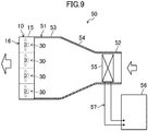
- the present embodiment is directed to an air conditioner (50) provided with the air-blowing apparatus (10) of the first embodiment.
- the air conditioner (50) of the present embodiment includes the air-blowing apparatus (10) of the first embodiment, a duct member (51), a heat exchanger (55), and an outdoor unit (56).
- the duct member (51) includes a blow-out end portion (53), a suction end portion (52), and an expanding portion (54).
- the blow-out end portion (53) is formed in a rectangular duct shape in size corresponding to the air-blowing apparatus (10).
- the suction end portion (52) is formed in a rectangular duct shape and has a smaller area of a flow path in a cross section than the blow-out end portion (53).
- the expanding portion (54) is formed in a shape in which the cross-sectional area of the flow path gradually increases from the suction end portion (52) toward the blow-out end portion (53). The expanding portion (54) connects the suction end portion (52) and the blow-out end portion (53).
- the main body (15) of the air-blowing apparatus (10) is arranged so as to cover a terminal end of the blow-out end portion (53) (left end in FIG. 9 ).
- the heat exchanger (55) is housed in the suction end portion (52).
- the heat exchanger (55) is an air heat exchanger that exchanges heat between refrigerant and air.
- the outdoor unit (56) is connected to the heat exchanger (55) via a pipe, and constitutes a refrigerant circuit (57) that performs a refrigeration cycle.
- the outdoor unit (56) houses devices such as a compressor, an outdoor fan, an outdoor heat exchanger, and the like.
- the air conditioner (50) of the present embodiment includes the air-blowing apparatus (10) of the first embodiment and the heat exchanger (55) that allows heat exchange of supply air to be sucked into the air-blowing apparatus (10) with a thermal medium to adjust the temperature of the supply air.
- the air conditioner (50) of the present embodiment blows out, by the air-blowing apparatus (10), the supply air which had its temperature adjusted while passing through the heat exchanger (55) Therefore, according to the air conditioner (50) of the present embodiment, both the flow rate and the temperature of the air blown out from the air-blowing apparatus (10) may be adjusted.
- the air conditioner (50) of the present embodiment may be provided with the air-blowing apparatus (10) of the variation of the first embodiment, or may be provided with the air-blowing apparatus (10) of the second embodiment or first and second variations thereof.
- the controller (40) may be configured to read the wind velocity data recorded on a recording medium, such as a memory card, and control the fans (30) of the main body (15), based on the read wind velocity data.
- a recording medium such as a memory card
- the air-blowing apparatus (10) of each of the foregoing embodiments and variations thereof may be configured to blow out the air from the blow-out region (16) such that the ratio (Vmax/Vmin) of the maximum value Vmax of wind velocity to the minimum value Vmin of the wind velocity is 1 or more and 5 or less in the target virtual plane (61).
- the air-blowing apparatus (10) of each of the foregoing embodiments and variations thereof may be configured to blow out air from the blow-out region (16) such that the ratio (Vmax/Vmin) of the maximum value Vmax of wind velocity to the minimum value Vmin of the wind velocity is 1 or more and 2.5 or less in the target virtual plane (61).
- the air-blowing apparatus (10) of each of the foregoing embodiments and variations thereof may be configured to blow out air from the blow-out region (16) such that the ratio (Vmax/Vmin) of the maximum value Vmax to the minimum value Vmin of wind velocity is a value within a predetermined value range in the third virtual plane (67) which is the target virtual plane (61).
- the air-blowing apparatus (10) of each of the foregoing embodiments and variations thereof may be configured to blow air from the blow-out region (16) such that the ratio (Vmax/Vmin) of the maximum value Vmax to the minimum value Vmin of wind velocity is a value within a predetermined value range in the plurality of target virtual planes (61).
- the type of the fan (30) is not limited to a propeller fan.
- the fan (30) may be a mixed flow fan or a sirocco fan.
- a so-called ion wind element may be provided as the blowing member in the main body (15).
- the ion wind element is an element configured to generate plasma by a discharge and generate wind by the generated plasma.
- the present disclosure is useful for an air-blowing apparatus and an air conditioner including the air-blowing apparatus.
Landscapes
- Engineering & Computer Science (AREA)
- Mechanical Engineering (AREA)
- General Engineering & Computer Science (AREA)
- Chemical & Material Sciences (AREA)
- Combustion & Propulsion (AREA)
- Physics & Mathematics (AREA)
- Fluid Mechanics (AREA)
- Thermal Sciences (AREA)
- Air Conditioning Control Device (AREA)
- Structures Of Non-Positive Displacement Pumps (AREA)
- Control Of Positive-Displacement Air Blowers (AREA)
- Air-Conditioning Room Units, And Self-Contained Units In General (AREA)
- Ventilation (AREA)
- Air-Flow Control Members (AREA)
Abstract
Description
- The present disclosure relates to an air-blowing apparatus and an air conditioner including the air-blowing apparatus.
-
Patent Document 1 discloses an air-blowing apparatus including a plurality of axial blowers. The air-blowing apparatus utilizes an inducing action by an air current blown out from the blowers to obtain a relatively large air-blowing volume. - Patent Document 1: Japanese Unexamined Patent Publication No.
2016-089734 - Wind (natural wind) blowing outdoors in a natural environment has a relatively small difference in velocity in different parts of a region whose area is about a frontal projection area of a typical adult man (approximately, 0.6 square meters). For this reason, natural wind has a relatively small difference in the velocity when blowing against different parts of the body of a person exposed to the wind.
- On the other hand, in many cases, a conventional air-blowing apparatus such as that disclosed in
Patent Document 1 is configured in consideration of obtaining a large air-blowing volume and increasing wind velocity to extend a reaching distance of an air current. This means that in a conventional air-blowing apparatus, not much of an emphasis has been put on averaging wind velocity distribution in a relatively large region. For this reason, a conventional air-blowing apparatus usually blows wind which has a relatively large difference in velocity when blowing against different parts of the body of a person exposed to the wind. Thus, the conventional air-blowing apparatus has not been able to provide a person with comfort similar to that when the person is exposed to natural wind. - An object of the present disclosure is to improve comfort of a person exposed to the wind blowing from an air-blowing apparatus.
- A first aspect of the present disclosure is directed to an air-blowing apparatus including: a main body (15) in which a blow-out region (16) for blowing out air is formed; and a blowing member (30) provided in the main body (15) and configured to send the air toward the blow-out region (16), wherein in a case in which a rectangular virtual plane that faces the blow-out region (16), is positioned at a distance of 1 m from the blow-out region (16), and has a long side extending in a vertical direction and having a length of 60 cm and a short side extending in a right-to-left direction and having a length of 45 cm is set as a front virtual plane (65), a rectangular virtual plane that faces the blow-out region (16), is positioned at a distance of 3 m from the blow-out region (16), and has a long side extending in the vertical direction and having a length of 180 cm and a short side extending in the right-to-left direction and having a length of 90 cm is set as a rear virtual plane (67), a virtual space having a shape of a truncated square pyramid and including the front virtual plane (65) and the rear virtual plane (67) as base planes is set as a target virtual space (60), and at least one of virtual planes included in the target virtual space (60) and parallel to the front virtual plane (65) is set as a target virtual plane (61), air is blown out from the blow-out region (16) such that a ratio (Vmax/Vmin) of a maximum value Vmax of wind velocity to a minimum value Vmin of the wind velocity is 1 or more and 10 or less in the target virtual plane (61).
- In the first aspect, the airflow generated by the blowing member (30) is sent out from the blow-out region (16) toward the target virtual plane (61). The ratio (Vmax/Vmin) of the maximum value Vmax to the minimum value Vmin of the wind velocity is 1 or more and 10 or less in each portion of the target virtual plane (61). For this reason, wind blown out from the blow-out region (16) has a relatively small difference in velocity when blowing against different parts of the body of a person exposed to the wind. Therefore, according to this aspect, comfort of the person exposed to the wind from the air-blowing apparatus (10) may be improved.
- A second aspect of the present disclosure is an embodiment of the first aspect. In the second aspect, air is blown out from the blow-out region (16) such that a ratio (Vmax/Vmin) of a maximum value Vmax of wind velocity to a minimum value Vmin of the wind velocity is 1 or more and 5 or less in the target virtual plane (61).
- In the target virtual plane (61), through which air blown out from the air-blowing apparatus (10) of the second aspect flows, the ratio (Vmax/Vmin) of the maximum value to the minimum value of wind velocity is 1 or more and 5 or less is each portion of the target virtual plane (61).
- A third aspect of the present disclosure is an embodiment of the first aspect. In the third aspect, air is blown out from the blow-out region (16) such that a ratio (Vmax/Vmin) of a maximum value Vmax of wind velocity to a minimum value Vmin of the wind velocity is 1 or more and 2.5 or less in the target virtual plane (61).
- In the target virtual plane (61) of the third aspect, through which air blown out from the air-blowing apparatus (10) flows, the ratio (Vmax/Vmin) of the maximum value to the minimum value of wind velocity is 1 or more and 2.5 or less is each portion of the target virtual plane (61).
- A fourth aspect of the present disclosure is an embodiment of any one of the first to third aspects. In the fourth aspect, in a case in which a rectangular virtual plane that faces the blow-out region (16), is positioned at a distance of 2 m from the blow-out region (16), and has a long side extending in the vertical direction and having a length of 120 cm and a short side extending in the right-to-left direction and having a length of 67.5 cm is set as a middle virtual plane (66), the target virtual plane (61) is located in a portion of the target virtual space (60) between the front virtual plane (65) and the middle virtual plane (66).
- In the fourth aspect, at least one of the virtual planes included in the target virtual space (60) between the front virtual plane (65) and the middle virtual plane (66), and parallel to the front virtual plane (65) is set as a target virtual plane (61).
- A fifth aspect of the present disclosure is an embodiment of any one of the first to third aspects. In the fifth aspect, the target virtual plane (61) is the rear virtual plane (67).
- In the fifth aspect, the rear virtual plane (67) is the target virtual plane (61). In the rear virtual plane (67), through which air blown out from the air-blowing apparatus (10) of the fifth aspect flows, the ratio (Vmax/Vmin) of the maximum value to the minimum value of wind velocity is within a predetermined value range in each portion of the rear virtual plane (67).
- A sixth aspect of the present disclosure is an embodiment of any one of the first to fifth aspects. In the sixth aspect, the blowing member is a plurality of fans (30) arranged so as to face the blow-out region (16).
- In the sixth aspect, the plurality of fans (30) are provided as the blowing members (30) in the air-blowing apparatus (10). When the fans (30) are operating, air is blown out from the blow-out region (16) of the main body (15).
- A seventh aspect of the present disclosure is an embodiment of any one of the first to fifth aspects. In the seventh aspect, the main body (15) includes a rectifying member (17) configured to allow air to pass therethrough and provided on the entire blow-out region (16), and the blowing member (30) is a fan (30) arranged upstream of the rectifying member (17).
- In a seventh aspect, the fan (30) is provided as the blowing member (30) in the air-blowing apparatus (10). The air blown out from the fan (30) is rectified when passing through the rectifying member (17), and then blown out from the blow-out region (16).
- An eighth aspect of the present disclosure is an embodiment of any one of the first to seventh aspects. In the eighth aspect, the air-blowing apparatus (10) further includes a controller (40) which controls operation of the blowing member (30), based on wind velocity data including a fluctuation pattern of wind velocity of outdoor natural wind obtained in advance or in real time, such that a fluctuation pattern of a flow rate of the air blown out from the blow-out region (16) is the fluctuation pattern of the wind velocity included in the wind velocity data.
- In the eighth aspect, the controller (40) controls the operation of the blowing member (30) such that the fluctuation pattern of the flow rate of air blown out from the blow-out region (16) is a fluctuation pattern of wind velocity included in the wind velocity data (that is, a fluctuation pattern of the wind velocity of outdoor natural wind). In other words, according to this aspect, the fluctuation pattern of the wind velocity of natural wind included in the wind velocity data may be reproduced by the air-blowing apparatus (10).
- A ninth aspect of the present disclosure is directed to an air conditioner including: the air-blowing apparatus (10) of any one of the first to eighth aspects; and a heat exchanger (55) which allows heat exchange of supply air to be sucked into the air-blowing apparatus (10) with a thermal medium to adjust a temperature of the supply air.
- In the ninth aspect, supply air whose temperature is adjusted while passing through the heat exchanger (55) is blown out by the air-blowing apparatus (10). Therefore, according to the air conditioner (50) of this aspect, both the flow rate and the temperature of the air blown out from the air-blowing apparatus (10) may be adjusted.
-
-
FIG. 1 is a schematic front view of a main body of an air-blowing apparatus of a first embodiment. -
FIG. 2 is a schematic perspective view illustrating the main body of the air-blowing apparatus of the first embodiment and a target virtual space. -
FIG. 3 is a schematic side view illustrating the main body of the air-blowing apparatus of the first embodiment and the target virtual space. -
FIG. 4 is a schematic configuration diagram illustrating a state of use of the air-blowing apparatus of the first embodiment. -
FIG. 5 is a schematic front view of a main body of an air-blowing apparatus of a second embodiment. -
FIG. 6 is a schematic cross-sectional view illustrating the main body of the air-blowing apparatus of the second embodiment taken along the line V-V ofFIG. 5 . -
FIG. 7 is a schematic cross-sectional view illustrating a cross section of a main body of an air-blowing apparatus of a first variation of the second embodiment, and corresponds toFIG. 6 . -
FIG. 8 is a schematic cross-sectional view illustrating a cross section of a main body of an air-blowing apparatus of a second variation of the second embodiment, and corresponds toFIG. 6 . -
FIG. 9 is a cross-sectional view illustrating a general configuration of an air conditioner of a third embodiment. - Hereinafter, an air-blowing apparatus (10) of a first embodiment will be described with reference to
FIGS. 1 to 4 , as necessary. - As shown in
FIGS. 1 and2 , the air-blowing apparatus (10) includes a main body (15). The main body (15) is formed in a rectangular parallelepiped shape having a relatively short depth in a front-rear direction. The main body (15) has a width in a right-to-left direction and a height in a vertical direction, each of approximately 1.6 m. Note that "upper", "lower", "left", "right", "front", and "rear" used in the description of the main body (15) refer to the directions shown inFIG. 2 (i.e., the directions when the main body (15) is viewed from the front). - The main body (15) is provided with sixteen fans (30) as blowing members. In the main body (15), the sixteen fans (30) are arranged in matrix, four in the right-to-left direction and four in a vertical direction. Each fan (30) is an axial blower including an impeller (31) and a shroud (32). The impeller (31) is a so-called propeller fan. The shroud (32) is arranged in each fan (30) to surround the circumference of the impeller (31). Although not shown, each fan (30) is provided with a fan motor for driving the impeller (31). The impeller (31) is attached to an output shaft of the fan motor.
- In the main body (15), the sixteen fans (30) face onto the front surface of the main body (15). The front surface of the main body (15) constitutes a blow-out region (16) from which the air that has been blown out from each fan (30) is blown out. In the air-blowing apparatus (10) of the present embodiment, the blow-out region (16) is a square plane having a width of 1.6 m in the right-to-left direction and a height of 1.6 m in the vertical direction.
- As shown in
FIG. 4 , the air-blowing apparatus (10) further includes a controller (40). Although not shown, the controller (40) includes a CPU that executes a control program, and a memory that stores the control program, data necessary for executing the control program, and the like. - The controller (40) is communicably connected to a sensor unit (46) installed outdoors at a remote location via a communication line (45) such as the Internet. Although not shown, the sensor unit (46) includes a single wind velocity sensor that measures velocity of wind (natural wind) blowing in the outdoor natural environment where the wind velocity sensor is installed. The sensor unit (46) transmits the measured value of the wind velocity sensor to the controller (40) via the communication line (45) in real time. The data sent from the sensor unit (46) to the controller (40) is wind velocity data including a record of a fluctuation pattern of natural wind at the installation location.
- The controller (40) is configured to control rotational speed of the impellers (31) of the fans (30) provided in the main body (15) based on the wind velocity data received from the sensor unit (46). At that time, the controller (40) sets the rotational speed of the impellers (31) of all the fans (30) to the same value.
- In the air-blowing apparatus (10) of the present embodiment, the impeller (31) of each fan (30) rotates at the same rotational speed. Therefore, each of the sixteen fans (30) arranged in matrix in the main body (15) blows out wind having substantially equal velocity. The air blown out by the sixteen fans (30) is blown forward from the blow-out region (16) which is the front surface of the main body (15).
- Streams of air which were blown out from each fan (30) and passed through the blow-out region (16) diffuse into each other. Thus, wind velocity of each stream is averaged. As a result, a ratio Vmax/Vmin of a maximum value Vmax to a minimum value Vmin of wind velocity is 1 or more and 10 or less (1≤Vmax/Vmin≤10) in each portion of the target virtual plane (61) shown in
FIG. 2 . Note that the ratio Vmax/Vmin of the maximum value Vmax to the minimum value Vmin of wind velocity in each portion of the target virtual plane (61) is preferably 1 or more and 5 or less, more preferably 1 or more and 4 or less, further preferably 1 or more and 3 or less, still preferably 1 or more and 2.5 or less, and particularly preferably 1 or more and 2 or less. - The controller (40) adjusts the rotational speed of the impeller (31) of each fan (30) such that a fluctuation pattern of flow rate of the air blown out from the blow-out region (16) is a fluctuation pattern of wind velocity included in the wind velocity data received from the sensor unit (46). That is, when the measured value of wind velocity included in the wind velocity data increases, the controller (40) boosts the rotational speed of the impeller (31) of each fan (30), and when the measured value of wind velocity included in the wind velocity data decreases, the controller (40) reduces the rotational speed of the impeller (31) of each fan (30). As a result, the fluctuation pattern of natural wind at the installation location of the sensor unit (46) is reproduced in the target virtual plane (61) which faces the blow-out region (16).
- As described above, the air-blowing apparatus (10) of the present embodiment sets the ratio Vmax/Vmin of the maximum value Vmax to the minimum value Vmin of wind velocity in each portion of the target virtual plane (61) to 1 or more and 10 or less . The reason for this will be now described.
- Unlike wind which is blown out from a common air conditioner, wind (natural wind) blowing outdoors in a natural environment is characterized in that "wind velocity distribution is relatively small in a relatively large area." To confirm that, the designers of the air-blowing apparatus (10) of the present embodiment actually measured natural wind velocity.
- The measured area was rectangular and had a width of 45 cm in a right-to-left direction and a height of 60 cm in a vertical direction. The designers measured natural wind velocity in each portion of the area. In the measured area, twenty wind velocity sensors were arranged in matrix. Specifically, in the measured area, four wind velocity sensors were arranged at intervals of 15 cm in the right-to-left direction and five wind velocity sensors were arranged at intervals of 15 cm in the vertical direction. Then, the designers recorded measured values of each of the wind velocity sensors every 0.5 second for 300 seconds, and calculated Vmax/Vmin of the measured area at each time. The results of measurement of wind velocity for 300 seconds were as follows: the minimum value of Vmax/Vmin was 1.2, and the maximum value of Vmax/Vmin was 4.6.
- The results of the measurement have shown that a person who faces the air-blowing apparatus (10) and is exposed to the wind blown therefrom feels as if being exposed to natural wind when the Vmax/Vmin in the target virtual plane (61) is set to approximately 10 or less. Therefore, Vmax/Vmin in the target virtual plane (61) is set to 1 or more and 5 or less in the air-blowing apparatus (10) of the present embodiment, which allows the person exposed to the wind from the air-blowing apparatus (10) to feel as if being exposed to natural wind and provide high comfort to the person.
- As shown in
FIGS. 2 and3 , a target virtual space (60) is a virtual space having a truncated square pyramid shape and includes a first virtual plane (65) and a third virtual plane (67) as base planes. The target virtual space (60) includes a second virtual plane (66). A target virtual plane (61) is a virtual plane included in the target virtual space (60). - The first virtual plane (65) is a front virtual plane. The first virtual plane (65) is a virtual plane indicated by the rectangle A1, B1, C1, D1 in
FIG. 2 . - Specifically, the first virtual plane (65) is a rectangular virtual plane facing the blow-out region (16). The first virtual plane (65) is a vertical plane parallel to the blow-out region (16). The distance from the first virtual plane (65) to the blow-out region (16) is 1 m. A long side of the first virtual plane (65) extends in the vertical direction. The long side of the first virtual plane (65) has a length of 60 cm. A short side of the first virtual plane (65) extends in the right-to-left direction. The short side of the first virtual plane (65) has a length of 45 cm.
- A center of gravity O1 of the first virtual plane (65) is located on a center line (CL) of the target virtual space (60). The center line (CL) of the target virtual space (60) is a horizontal straight line perpendicular to the first virtual plane (65) and the blow-out region (16).
- The second virtual plane (66) is a middle virtual plane. The second virtual plane (66) is a virtual plane indicated by the rectangle A2, B2, C2, D2 in
FIG. 2 . The second virtual plane (66) is located midway between the first virtual plane (65) and the third virtual plane (67). - Specifically, the second virtual plane (66) is a rectangular virtual plane facing the blow-out region (16). The second virtual plane (66) is a vertical plane parallel to the blow-out region (16). The distance from the second virtual plane (66) to the blow-out region (16) is 2 m. A long side of the second virtual plane (66) extends in the vertical direction. The long side of the second virtual plane (66) has a length of 120 cm. A short side of the second virtual plane (66) extends in the right-to-left direction. The short side of the second virtual plane (66) has a length of 67.5 cm.
- A center of gravity O2 of the second virtual plane (66) is located on the center line (CL) of the target virtual space (60). The second virtual plane (66) is perpendicular to the center line (CL) of the target virtual space (60).
- The third virtual plane (67) is a rear virtual plane. The third virtual plane (67) is a virtual plane indicated by the rectangle A3, B3, C3, D3 in
FIG. 2 . - Specifically, the third virtual plane (67) is a rectangular virtual plane facing the blow-out region (16). The third virtual plane (67) is a vertical plane parallel to the blow-out region (16). The distance from the third virtual plane (67) to the blow-out region (16) is 3 m. A long side of the third virtual plane (67) extends in the vertical direction. The long side of the third virtual plane (67) has a length of 180 cm. A short side of the third virtual plane (67) extends in the right-to-left direction. The short side of the third virtual plane (67) has a length of 90 cm.
- A center of gravity O3 of the third virtual plane (67) is located on the center line (CL) of the target virtual space (60). The third virtual plane (67) is perpendicular to the center line (CL) of the target virtual space (60).
- The target virtual plane (61) of the present embodiment is a virtual plane indicated by the rectangle A, B, C, D in
FIG. 2 . The target virtual plane (61) is a virtual plane included in the target virtual space (60) and parallel to the first virtual plane (65). - Specifically, the target virtual plane (61) is a rectangular virtual plane facing the blow-out region (16). The target virtual plane (61) is a vertical plane parallel to the blow-out region (16). In the target virtual space (60), the target virtual plane (61) of the present embodiment is located between the first virtual plane (65) and the second virtual plane (66). A long side of the target virtual plane (61) extends in the vertical direction. A short side of the target virtual plane (61) extends in the right-to-left direction.
- A center of gravity O of the target virtual plane (61) is located on the center line (CL) of the target virtual space (60). The target virtual plane (61) is perpendicular to the center line (CL) of the target virtual space (60).
- The air-blowing apparatus (10) of the present embodiment includes the main body (15) in which the planar blow-out region (16) for blowing air is formed, and the fans (30) provided in the main body (15) and configured to send the air toward the blow-out region (16). In addition, the air-blowing apparatus (10) blows the air from the blow-out region (16) such that the ratio (Vmax/Vmin) of the maximum value Vmax of wind velocity to the minimum value Vmin of the wind velocity is 1 or more and 10 or less in the target virtual plane (61).
- The target virtual plane (61) is at least one of the virtual planes included in the target virtual space (60) and parallel to the first virtual plane (65). The target virtual space (60) is a virtual space having a truncated square pyramid shape. The target virtual space (60) includes a first virtual plane (65) and a third virtual plane (67) as base planes. The first virtual plane (65) is a rectangular virtual plane which faces the blow-out region (16) and is positioned at a distance of 1 m from the blow-out region (16). The long side of the first virtual plane (65) extends in the vertical direction and has a length of 60 cm. The short side of the first virtual plane (65) extends in the right-to-left direction and has a length of 45 cm. The third virtual plane (67) is a rectangular virtual plane which faces the blow-out region (16) and is positioned at a distance of 3 m from the blow-out region (16). The long side of the third virtual plane (67) extends in the vertical direction and has a length of 180 cm. The short side of the third virtual plane (67) extends in the right-to-left direction and has a length of 90 cm.
- In the present embodiment, the airflow generated by the blowing members (30) is sent out from the blow-out region (16) toward the target virtual plane (61). The ratio (Vmax/Vmin) of the maximum value Vmax to the minimum value Vmin of wind velocity is 1 or more and 10 or less in each portion of the target virtual plane (61). For this reason, wind blown out from the blow-out region (16) has a relatively small difference in velocity when blowing against different parts of the body of a person exposed to the wind. Consequently, the present embodiment may provide a person with comfort similar to that when the person is exposed to natural wind, and may improve comfort of the person exposed to the wind from the air-blowing apparatus (10).
- The target virtual plane (61) of the present embodiment is located in a portion of the target virtual space (60) between the first virtual plane (65) and the second virtual plane (66). The second virtual plane (66) is a rectangular virtual plane which faces the blow-out region (16) and is positioned at a distance of 2 m from the blow-out region (16). The long side of the second virtual plane (66) extends in the vertical direction and has a length of 120 cm. The short side of the second virtual plane (66) extends in the right-to-left direction and has a length of 67.5 cm.
- In the air-blowing apparatus (10) of the present embodiment, the plurality of fans (30) constituting the blowing members are arranged so as to face onto the blow-out region (16). When the fans (30) are operating, air is blown out from the blow-out region (16) of the main body (15).
- In the air-blowing apparatus (10) of the present embodiment, the controller (40) controls operation of the fans (30), based on the wind velocity data including a fluctuation pattern of a wind velocity of outdoor natural wind obtained in real time, such that the fluctuation pattern of the flow rate of the air blown from the blow-out region (16) is the fluctuation pattern of the wind velocity included in the wind velocity data. Consequently, according to the present embodiment, the air-blowing apparatus (10) may reproduce the fluctuation pattern of natural wind velocity included in the wind velocity data.
- The sensor unit (46) may be provided with a plurality of wind velocity sensors.
- For example, in a case in which four of the wind velocity sensors are provided in the sensor unit (46), the wind velocity sensors are desirably arranged in matrix, two in the right-to-left direction and two in the vertical direction. In this case, in the main body (15), the four fans (30) located on the upper side on the right are associated with the first wind velocity sensor; the four fans (30) located on the lower side on the right are associated with the second wind velocity sensor; the four fans (30) located on the lower side on the left are associated with the third wind velocity sensor; and the four fans (30) located on the upper side on the left are associated with the fourth wind velocity sensor. The controller (40) adjusts the rotational speed of the impeller (31) of each fan (30) depending on the measured values of the corresponding wind velocity sensors.
- Further, for example, in a case in which sixteen wind velocity sensors are provided in the sensor unit (46), each of the sixteen fans (30) provided in the main body (15) is associated with a different wind velocity sensor. In this case, the controller (40) individually adjusts the rotational speed of the impeller (31) of each of the fans (30) depending on the measured value of the wind velocity sensor corresponding to each fan (30).
- A second embodiment will be now described. An air-blowing apparatus (10) of the present embodiment is a modified version of the air-blowing apparatus (10) of the first embodiment, in which the configuration of the main body (15) has been modified. Here, the main body (15) of the present embodiment will be described with reference to
FIGS. 5 and6 . - The main body (15) of the present embodiment includes one casing (20), one fan (30), and one rectifying member (17). The main body (15) is formed in a rectangular parallelepiped shape having a relatively short depth in a front-rear direction.
- The casing (20) is formed in a square frame shape (or a short rectangular duct shape) when viewed from the front. The casing (20) has a width in the right-to-left direction and a height in the vertical direction, each of approximately 1.6 m.
- The fan (30) is housed in the casing (20), and arranged closer to the rear end of the casing (20). The fan (30) of the present embodiment is an axial blower similar to the fans (30) of the first embodiment. The fan (30) includes one impeller (31), one fan motor (33), and one shroud (32).
- The rectifying member (17) is a member configured to allow air to pass therethrough and to adjust flow of air passing therethrough. The rectifying member (17) is formed of, for example, a plurality of stacked non-woven fabric sheets, a punching plate in which multiple small holes are formed, or the like. The rectifying member (17) of the present embodiment is formed in a thick square plate-like shape, and is arranged so as to cover an entire opening end on a front surface side of the casing (20). In the main body (15) of the present embodiment, the front surface of the rectifying member (17) serves as a blow-out region (16). Consequently, in the air-blowing apparatus (10) of the present embodiment, as well, the blow-out region (16) is a square plane having a width of 1.6 m in the right-to-left direction and a height of 1.6 m in the vertical direction.
- In the air-blowing apparatus (10) of the present embodiment, the controller (40) performs a control of the single fan (30) provided in the main body (15). That is, the controller (40) adjusts the rotational speed of the impeller (31) of the fan (30) based on the data on air blow received from the sensor unit (46).
- In the air-blowing apparatus (10) of the present embodiment, the flow of the air blown from the fan (30) is adjusted when the air passes through the rectifying member (17). Then, in the blow-out region (16) which is the front surface of the rectifying member (17), the flow rate of the air passing through each portion of the blow-out region (16) is averaged. As a result, the ratio Vmax/Vmin of the maximum value Vmax to the minimum value Vmin of wind velocity is 1 or more and 5 or less (1 ≤ Vmax/Vmin ≤ 5) in each portion of the target virtual plane (61) which faces the blow-out region (16). Note that a shape and size of the target virtual plane (61), and the distance from the target virtual plane (61) to the blow-out region (16) are the same as those of the first embodiment.
- As described above, in the air-blowing apparatus (10) of the present embodiment, the main body (15) includes the rectifying member (17) configured to allow air to pass therethrough and provided on the entire blow-out region (16). In addition, the fan (30) which is the blowing member is arranged upstream of the rectifying member (17) in the main body (15). In the air-blowing apparatus (10) of the present embodiment, air blown out from the fan (30) is rectified when passing through the rectifying member (17), and then blown out from the blow-out region (16).
- As shown in
FIG. 7 , in the air-blowing apparatus (10) of the present embodiment, the casing (20) of the main body (15) may be divided into a suction side casing (21) and a blow-out side casing (22). The single fan (30) is housed in the suction side casing (21). The rectifying member (17) is attached to the blow-out side casing (22) so as to cover the front surface thereof. The suction side casing (21) and the blow-out side casing (22) are connected by a bellows-shaped connecting duct (25). - As shown in
FIG. 8 , the air-blowing apparatus (10) of the present embodiment may be arranged such that the fan (30) blows air upward. - The casing (20) of the present variation is formed in a box-like rectangular parallelepiped shape. The casing (20) has an upper portion of the front surface open, and the rectifying member (17) is attached so as to cover the opening. The casing (20) has a front side plate and a rear side plate. The front side plate and the rear side plate each have an inlet (23) formed near a lower end. The fan (30) is arranged above the inlet (23) and below the rectifying member (17) in an internal space of the casing (20). Further, the fan (30) is installed in the casing (20) such that a rotation axis of the impeller (31) is directed vertically. Note that the shroud of the fan (30) is not shown in
FIG. 8 . - When the fan (30) is operating, air flows through the inlets (23) and into the internal space of the casing (20). The air that has flowed into the internal space of the casing (20) is blown upward by the fan (30), and turned forward. Then, the air passes through the rectifying member (17) and is blown out from the casing (20).
- The air-blowing apparatus (10) of the present embodiment and the first and second variations thereof may be provided with a plurality of fans (30). For example, four fans (30) may be arranged in the casing (20) in matrix in the air-blowing apparatus (10) of the present embodiment and the first and second variations thereof.
- A third embodiment will be now described. The present embodiment is directed to an air conditioner (50) provided with the air-blowing apparatus (10) of the first embodiment.
- As shown in
FIG. 9 , the air conditioner (50) of the present embodiment includes the air-blowing apparatus (10) of the first embodiment, a duct member (51), a heat exchanger (55), and an outdoor unit (56). - The duct member (51) includes a blow-out end portion (53), a suction end portion (52), and an expanding portion (54). The blow-out end portion (53) is formed in a rectangular duct shape in size corresponding to the air-blowing apparatus (10). The suction end portion (52) is formed in a rectangular duct shape and has a smaller area of a flow path in a cross section than the blow-out end portion (53). The expanding portion (54) is formed in a shape in which the cross-sectional area of the flow path gradually increases from the suction end portion (52) toward the blow-out end portion (53). The expanding portion (54) connects the suction end portion (52) and the blow-out end portion (53).
- The main body (15) of the air-blowing apparatus (10) is arranged so as to cover a terminal end of the blow-out end portion (53) (left end in
FIG. 9 ). The heat exchanger (55) is housed in the suction end portion (52). The heat exchanger (55) is an air heat exchanger that exchanges heat between refrigerant and air. The outdoor unit (56) is connected to the heat exchanger (55) via a pipe, and constitutes a refrigerant circuit (57) that performs a refrigeration cycle. Although not illustrated, the outdoor unit (56) houses devices such as a compressor, an outdoor fan, an outdoor heat exchanger, and the like. - When the fan (30) of the air-blowing apparatus (10) is operating, air is sucked into the suction end (52) of the duct member (51). The air that has been sucked into the duct member (51) flows in the duct member (51) as supply air. The air is then cooled or heated by exchanging heat with the refrigerant while passing through the heat exchanger (55). The supply air has its temperature adjusted while passing through the heat exchanger (55), and then is blown into an indoor space by the air-blowing apparatus (10).
- As described above, the air conditioner (50) of the present embodiment includes the air-blowing apparatus (10) of the first embodiment and the heat exchanger (55) that allows heat exchange of supply air to be sucked into the air-blowing apparatus (10) with a thermal medium to adjust the temperature of the supply air.
- The air conditioner (50) of the present embodiment blows out, by the air-blowing apparatus (10), the supply air which had its temperature adjusted while passing through the heat exchanger (55) Therefore, according to the air conditioner (50) of the present embodiment, both the flow rate and the temperature of the air blown out from the air-blowing apparatus (10) may be adjusted.
- Instead of the air-blowing apparatus (10) of the first embodiment, the air conditioner (50) of the present embodiment may be provided with the air-blowing apparatus (10) of the variation of the first embodiment, or may be provided with the air-blowing apparatus (10) of the second embodiment or first and second variations thereof.
- In the air-blowing apparatus (10) of each of the foregoing embodiments and variations thereof, the controller (40) may be configured to read the wind velocity data recorded on a recording medium, such as a memory card, and control the fans (30) of the main body (15), based on the read wind velocity data.
- The air-blowing apparatus (10) of each of the foregoing embodiments and variations thereof may be configured to blow out the air from the blow-out region (16) such that the ratio (Vmax/Vmin) of the maximum value Vmax of wind velocity to the minimum value Vmin of the wind velocity is 1 or more and 5 or less in the target virtual plane (61).
- In addition, the air-blowing apparatus (10) of each of the foregoing embodiments and variations thereof may be configured to blow out air from the blow-out region (16) such that the ratio (Vmax/Vmin) of the maximum value Vmax of wind velocity to the minimum value Vmin of the wind velocity is 1 or more and 2.5 or less in the target virtual plane (61).
- Further, the air-blowing apparatus (10) of each of the foregoing embodiments and variations thereof may be configured to blow out air from the blow-out region (16) such that the ratio (Vmax/Vmin) of the maximum value Vmax to the minimum value Vmin of wind velocity is a value within a predetermined value range in the third virtual plane (67) which is the target virtual plane (61).
- Additionally, the air-blowing apparatus (10) of each of the foregoing embodiments and variations thereof may be configured to blow air from the blow-out region (16) such that the ratio (Vmax/Vmin) of the maximum value Vmax to the minimum value Vmin of wind velocity is a value within a predetermined value range in the plurality of target virtual planes (61).
- In the air-blowing apparatus (10) of each of the foregoing embodiments and variations thereof, the type of the fan (30) is not limited to a propeller fan. For example, the fan (30) may be a mixed flow fan or a sirocco fan.
- In the air-blowing apparatus (10) of each of the foregoing embodiments and variations thereof, a so-called ion wind element may be provided as the blowing member in the main body (15). The ion wind element is an element configured to generate plasma by a discharge and generate wind by the generated plasma.
- While embodiments and variations have been described above, it will be understood that various modifications in form and detail may be made without departing from the spirit and scope of the present disclosure as set forth in the appended claims. The foregoing embodiments and variations may be appropriately combined or replaced unless the function of the target of the present disclosure is impaired.
- As described above, the present disclosure is useful for an air-blowing apparatus and an air conditioner including the air-blowing apparatus.
-
- 15
- Main Body
- 16
- Blow-out Region
- 17
- Rectifying Member
- 30
- Fan (Blowing Member)
- 40
- Controller
- 50
- Air Conditioner
- 55
- Heat Exchanger
- 60
- Target Virtual Space
- 61
- Target Virtual Plane
- 65
- First Virtual Plane (Front Virtual Plane)
- 66
- Second Virtual Plane (Middle Virtual Plane)
- 67
- Third Virtual Plane (Rear Virtual Plane)
Claims (9)
- An air-blowing apparatus comprising: a main body (15) in which a blow-out region (16) for blowing out air is formed; and a blowing member (30) provided in the main body (15) and configured to send the air toward the blow-out region (16), wherein
in a case in whicha rectangular virtual plane that faces the blow-out region (16), is positioned at a distance of 1 m from the blow-out region (16), and has a long side extending in a vertical direction and having a length of 60 cm and a short side extending in a right-to-left direction and having a length of 45 cm is set as a front virtual plane (65),a rectangular virtual plane that faces the blow-out region (16), is positioned at a distance of 3 m from the blow-out region (16), and has a long side extending in the vertical direction and having a length of 180 cm and a short side extending in the right-to-left direction and having a length of 90 cm is set as a rear virtual plane (67),a virtual space having a shape of a truncated square pyramid and including the front virtual plane and the rear virtual plane as base planes is set as a target virtual space (60), andat least one of virtual planes included in the target virtual space (60) and parallel to the front virtual plane (65) is set as a target virtual plane (61),air is blown out from the blow-out region (16) such that a ratio (Vmax/Vmin) of a maximum value Vmax of wind velocity to a minimum value Vmin of the wind velocity is 1 or more and 10 or less in the target virtual plane (61). - The air-blowing apparatus of claim 1, wherein
air is blown out from the blow-out region (16) such that the ratio (Vmax/Vmin) of the maximum value Vmax of wind velocity to the minimum value Vmin of the wind velocity is 1 or more and 5 or less in the target virtual plane (61). - The air-blowing apparatus of claim 1, wherein
air is blown out from the blow-out region (16) such that the ratio (Vmax/Vmin) of the maximum value Vmax of wind velocity to the minimum value Vmin of the wind velocity is 1 or more and 2.5 or less in the target virtual plane (61). - The air-blowing apparatus of any one of claims 1 to 3, wherein
in a case in which a rectangular virtual plane that faces the blow-out region (16), is positioned at a distance of 2 m from the blow-out region (16), and has a long side extending in the vertical direction and having a length of 120 cm and a short side extending in the right-to-left direction and having a length of 67.5 cm is set as a middle virtual plane (66),
the target virtual plane (61) is located in a portion of the target virtual space (60) between the front virtual plane (65) and the middle virtual plane (66). - The air-blowing apparatus of any one of claims 1 to 3, wherein
the target virtual plane (61) is the rear virtual plane (67). - The air-blowing apparatus of any one of claims 1 to 5, wherein
the blowing member is a plurality of fans (30) arranged so as to face the blow-out region (16). - The air-blowing apparatus of any one of claims 1 to 5, wherein
the main body (15) includes a rectifying member (17) configured to allow air to pass therethrough and provided on the entire blow-out region (16), and
the blowing member (30) is a fan (30) arranged upstream of the rectifying member (17). - The air-blowing apparatus of any one of claims 1 to 7, further comprising
a controller (40) which controls operation of the blowing member (30), based on wind velocity data including a fluctuation pattern of wind velocity of outdoor natural wind obtained in advance or in real time, such that a fluctuation pattern of a flow rate of the air blown out from the blow-out region (16) is the fluctuation pattern of the wind velocity included in the wind velocity data. - An air conditioner comprising:the air-blowing apparatus (10) of any one of claims 1 to 8; anda heat exchanger (55) which allows heat exchange of supply air to be sucked into the air-blowing apparatus (10) with a thermal medium to adjust a temperature of the supply air.
Applications Claiming Priority (2)
| Application Number | Priority Date | Filing Date | Title |
|---|---|---|---|
| JP2018030601 | 2018-02-23 | ||
| PCT/JP2019/006729 WO2019163934A1 (en) | 2018-02-23 | 2019-02-22 | Air blowing device and air conditioning device |
Publications (2)
| Publication Number | Publication Date |
|---|---|
| EP3754205A1 true EP3754205A1 (en) | 2020-12-23 |
| EP3754205A4 EP3754205A4 (en) | 2021-10-20 |
Family
ID=67688399
Family Applications (1)
| Application Number | Title | Priority Date | Filing Date |
|---|---|---|---|
| EP19757862.8A Withdrawn EP3754205A4 (en) | 2018-02-23 | 2019-02-22 | AIR BLOW DEVICE AND AIR CONDITIONING |
Country Status (5)
| Country | Link |
|---|---|
| US (1) | US11852359B2 (en) |
| EP (1) | EP3754205A4 (en) |
| JP (2) | JP2019143631A (en) |
| CN (2) | CN113464478A (en) |
| WO (1) | WO2019163934A1 (en) |
Families Citing this family (10)
| Publication number | Priority date | Publication date | Assignee | Title |
|---|---|---|---|---|
| CN113464478A (en) * | 2018-02-23 | 2021-10-01 | 大金工业株式会社 | Air supply device |
| JP2021139511A (en) * | 2020-03-02 | 2021-09-16 | ダイキン工業株式会社 | Control device of environment adjustment device |
| JP7437721B2 (en) * | 2020-06-15 | 2024-02-26 | 昭弘 畠山 | Air blower, electric fan and air blowing system using the same |
| EP4306736B1 (en) | 2021-04-27 | 2025-05-14 | Daikin Industries, Ltd. | Partition |
| CN113606760B (en) * | 2021-07-28 | 2022-07-12 | 珠海格力电器股份有限公司 | Temperature adjusting device control method and device, electronic device and storage medium |
| JP7668769B2 (en) | 2022-06-08 | 2025-04-25 | 三菱電機株式会社 | Blower |
| CN115218426B (en) * | 2022-07-01 | 2026-02-10 | 青岛海尔空调器有限总公司 | Air conditioner control methods, devices and air conditioners |
| CN115929668B (en) * | 2022-09-16 | 2025-02-14 | 上海电气斯必克工程技术有限公司 | Compensation method for direct air cooling fan speed to ambient air and tube bundle temperature |
| WO2024154735A1 (en) * | 2023-01-19 | 2024-07-25 | ダイキン工業株式会社 | Blowing amount adjustment device and blowing system |
| WO2025015314A1 (en) * | 2023-07-13 | 2025-01-16 | Price Industries Limited | Sound-reducing exhaust air system |
Family Cites Families (23)
| Publication number | Priority date | Publication date | Assignee | Title |
|---|---|---|---|---|
| JPH0694291A (en) * | 1992-09-16 | 1994-04-05 | Hitachi Ltd | Air conditioner |
| JPH06123481A (en) * | 1992-10-09 | 1994-05-06 | Mitsubishi Heavy Ind Ltd | Air conditioner control device |
| JP2967679B2 (en) * | 1993-11-05 | 1999-10-25 | 株式会社明電舎 | Ventilation automatic control device |
| JP3358384B2 (en) * | 1995-05-17 | 2002-12-16 | 松下電器産業株式会社 | Control device for air conditioner |
| JP4234413B2 (en) * | 2002-12-13 | 2009-03-04 | 愛知電機株式会社 | Drive control device for blower |
| WO2004085928A2 (en) * | 2003-03-20 | 2004-10-07 | Huntair Inc. | Fan array fan section in air-handling systems |
| US7597534B2 (en) * | 2003-03-20 | 2009-10-06 | Huntair, Inc. | Fan array fan section in air-handling systems |
| JP2011089444A (en) * | 2009-10-21 | 2011-05-06 | Masaki Chigira | Super-thin panel type laminar flow air blower |
| MY164300A (en) | 2009-10-27 | 2017-12-15 | Nortek Air Solutions Llc | Fan array control system |
| EP2522921B1 (en) * | 2010-02-15 | 2019-03-06 | Koken Ltd. | Local clean zone forming apparatus |
| CN102486179A (en) * | 2010-12-13 | 2012-06-06 | 杜文娟 | Natural wind simulating electric fan and utilization method thereof |
| JP5484421B2 (en) | 2011-07-29 | 2014-05-07 | 興研株式会社 | Local air purifier |
| JP5808986B2 (en) * | 2011-09-06 | 2015-11-10 | 興研株式会社 | Air blowing device |
| CN103062086B (en) * | 2011-10-20 | 2016-01-20 | 中强光电股份有限公司 | Cooling system and control method thereof |
| JP2016011827A (en) * | 2014-06-05 | 2016-01-21 | 三星電子株式会社Samsung Electronics Co.,Ltd. | Ceiling embedded type indoor equipment and air conditioner using the same |
| JP2016089734A (en) | 2014-11-06 | 2016-05-23 | パナソニックIpマネジメント株式会社 | Blower |
| JP2016169890A (en) * | 2015-03-11 | 2016-09-23 | パナソニックIpマネジメント株式会社 | Blower |
| CN204851735U (en) * | 2015-08-19 | 2015-12-09 | 杭州冷倍冠科技有限公司 | Electric fan control system |
| JP6603874B2 (en) * | 2015-12-22 | 2019-11-13 | パナソニックIpマネジメント株式会社 | Blower and air purifier with blower function |
| CN106594869B (en) * | 2016-11-29 | 2020-05-29 | 青岛海尔空调器有限总公司 | Indoor unit of air conditioner |
| JP7110546B2 (en) | 2016-12-01 | 2022-08-02 | トヨタ自動車株式会社 | Method for determining whether an object can be lifted |
| CN206738203U (en) * | 2017-04-07 | 2017-12-12 | 中国科学院声学研究所 | A kind of silent ventilator based on fan unit integrated array structure |
| CN113464478A (en) * | 2018-02-23 | 2021-10-01 | 大金工业株式会社 | Air supply device |
-
2019
- 2019-02-22 CN CN202110784233.5A patent/CN113464478A/en active Pending
- 2019-02-22 EP EP19757862.8A patent/EP3754205A4/en not_active Withdrawn
- 2019-02-22 CN CN201980012656.6A patent/CN111699322A/en active Pending
- 2019-02-22 WO PCT/JP2019/006729 patent/WO2019163934A1/en not_active Ceased
- 2019-02-22 JP JP2019030061A patent/JP2019143631A/en active Pending
-
2020
- 2020-08-21 US US16/999,670 patent/US11852359B2/en active Active
- 2020-09-02 JP JP2020147724A patent/JP7248914B2/en active Active
Also Published As
| Publication number | Publication date |
|---|---|
| JP2019143631A (en) | 2019-08-29 |
| JP7248914B2 (en) | 2023-03-30 |
| CN113464478A (en) | 2021-10-01 |
| US11852359B2 (en) | 2023-12-26 |
| US20200378625A1 (en) | 2020-12-03 |
| EP3754205A4 (en) | 2021-10-20 |
| JP2021006714A (en) | 2021-01-21 |
| CN111699322A (en) | 2020-09-22 |
| WO2019163934A1 (en) | 2019-08-29 |
Similar Documents
| Publication | Publication Date | Title |
|---|---|---|
| US11852359B2 (en) | Air blowing apparatus and air conditioner | |
| JP2021006714A5 (en) | ||
| JP5194023B2 (en) | Embedded ceiling air conditioner | |
| EP2568226B1 (en) | Indoor unit for air-conditioning apparatus and air-conditioning apparatus including indoor unit | |
| CN107250682B (en) | Indoor unit of air conditioner | |
| CN209819709U (en) | wall mounted air conditioner indoor unit | |
| CN113124496A (en) | Cabinet air conditioner indoor unit and cabinet air conditioner | |
| JPWO2009020173A1 (en) | Blower and air conditioner | |
| JP6848956B2 (en) | Indoor unit of air conditioner | |
| JP2019219085A (en) | Replacement type air conditioning device | |
| US11493231B2 (en) | Indoor unit for air conditioner | |
| CN112204208A (en) | Air supply device | |
| CN209840282U (en) | wall mounted air conditioner indoor unit | |
| JP6453951B1 (en) | Variable air volume coanda air conditioning system | |
| CN112136005B (en) | Air blower and air conditioner | |
| CN112710073A (en) | Air deflector and air conditioner with same | |
| CN215260137U (en) | Cabinet air conditioner indoor unit and cabinet air conditioner | |
| JP6923845B2 (en) | Duct type air conditioner | |
| JPH06159783A (en) | Blowoff chamber | |
| CN209445499U (en) | Indoor unit of air conditioner | |
| JP4997888B2 (en) | Ventilation equipment | |
| CN114963327B (en) | Wall-mounted air conditioner indoor unit | |
| JP2016169890A (en) | Blower | |
| JP6648593B2 (en) | Air conditioner | |
| JP2001349600A (en) | Air conditioner |
Legal Events
| Date | Code | Title | Description |
|---|---|---|---|
| STAA | Information on the status of an ep patent application or granted ep patent |
Free format text: STATUS: THE INTERNATIONAL PUBLICATION HAS BEEN MADE |
|
| PUAI | Public reference made under article 153(3) epc to a published international application that has entered the european phase |
Free format text: ORIGINAL CODE: 0009012 |
|
| STAA | Information on the status of an ep patent application or granted ep patent |
Free format text: STATUS: REQUEST FOR EXAMINATION WAS MADE |
|
| 17P | Request for examination filed |
Effective date: 20200916 |
|
| AK | Designated contracting states |
Kind code of ref document: A1 Designated state(s): AL AT BE BG CH CY CZ DE DK EE ES FI FR GB GR HR HU IE IS IT LI LT LU LV MC MK MT NL NO PL PT RO RS SE SI SK SM TR |
|
| AX | Request for extension of the european patent |
Extension state: BA ME |
|
| DAV | Request for validation of the european patent (deleted) | ||
| DAX | Request for extension of the european patent (deleted) | ||
| REG | Reference to a national code |
Ref country code: DE Ref legal event code: R079 Free format text: PREVIOUS MAIN CLASS: F04D0029560000 Ipc: F04D0025080000 |
|
| A4 | Supplementary search report drawn up and despatched |
Effective date: 20210921 |
|
| RIC1 | Information provided on ipc code assigned before grant |
Ipc: F24F 13/08 20060101ALN20210915BHEP Ipc: F24F 11/74 20180101ALI20210915BHEP Ipc: F24F 7/007 20060101ALI20210915BHEP Ipc: F24F 1/0029 20190101ALI20210915BHEP Ipc: F04D 29/70 20060101ALI20210915BHEP Ipc: F04D 29/54 20060101ALI20210915BHEP Ipc: F04D 29/44 20060101ALI20210915BHEP Ipc: F04D 27/00 20060101ALI20210915BHEP Ipc: F04D 25/16 20060101ALI20210915BHEP Ipc: F04D 25/08 20060101AFI20210915BHEP |
|
| RAP3 | Party data changed (applicant data changed or rights of an application transferred) |
Owner name: DAIKIN INDUSTRIES, LTD. |
|
| P01 | Opt-out of the competence of the unified patent court (upc) registered |
Effective date: 20230525 |
|
| STAA | Information on the status of an ep patent application or granted ep patent |
Free format text: STATUS: EXAMINATION IS IN PROGRESS |
|
| 17Q | First examination report despatched |
Effective date: 20230706 |
|
| STAA | Information on the status of an ep patent application or granted ep patent |
Free format text: STATUS: THE APPLICATION HAS BEEN WITHDRAWN |
|
| 18W | Application withdrawn |
Effective date: 20231013 |