EP3754172A1 - Verfahren zur ansteuerung eines verbrennungsmotors - Google Patents
Verfahren zur ansteuerung eines verbrennungsmotors Download PDFInfo
- Publication number
- EP3754172A1 EP3754172A1 EP20155837.6A EP20155837A EP3754172A1 EP 3754172 A1 EP3754172 A1 EP 3754172A1 EP 20155837 A EP20155837 A EP 20155837A EP 3754172 A1 EP3754172 A1 EP 3754172A1
- Authority
- EP
- European Patent Office
- Prior art keywords
- combustion engine
- internal combustion
- speed
- operating characteristic
- self
- Prior art date
- Legal status (The legal status is an assumption and is not a legal conclusion. Google has not performed a legal analysis and makes no representation as to the accuracy of the status listed.)
- Granted
Links
- 238000002485 combustion reaction Methods 0.000 title claims abstract description 84
- 238000000034 method Methods 0.000 title claims abstract description 16
- 238000003306 harvesting Methods 0.000 claims description 22
- 210000000056 organ Anatomy 0.000 claims description 7
- 230000004913 activation Effects 0.000 claims description 2
- 238000010586 diagram Methods 0.000 description 10
- 239000000446 fuel Substances 0.000 description 4
- 230000001276 controlling effect Effects 0.000 description 3
- 239000000463 material Substances 0.000 description 2
- 241000196324 Embryophyta Species 0.000 description 1
- 240000008042 Zea mays Species 0.000 description 1
- 235000005824 Zea mays ssp. parviglumis Nutrition 0.000 description 1
- 235000002017 Zea mays subsp mays Nutrition 0.000 description 1
- 230000005540 biological transmission Effects 0.000 description 1
- 239000003990 capacitor Substances 0.000 description 1
- 235000005822 corn Nutrition 0.000 description 1
- 238000004146 energy storage Methods 0.000 description 1
- 239000004459 forage Substances 0.000 description 1
- 230000001105 regulatory effect Effects 0.000 description 1
Images


Classifications
-
- F—MECHANICAL ENGINEERING; LIGHTING; HEATING; WEAPONS; BLASTING
- F02—COMBUSTION ENGINES; HOT-GAS OR COMBUSTION-PRODUCT ENGINE PLANTS
- F02D—CONTROLLING COMBUSTION ENGINES
- F02D41/00—Electrical control of supply of combustible mixture or its constituents
- F02D41/02—Circuit arrangements for generating control signals
- F02D41/14—Introducing closed-loop corrections
- F02D41/1497—With detection of the mechanical response of the engine
-
- F—MECHANICAL ENGINEERING; LIGHTING; HEATING; WEAPONS; BLASTING
- F02—COMBUSTION ENGINES; HOT-GAS OR COMBUSTION-PRODUCT ENGINE PLANTS
- F02D—CONTROLLING COMBUSTION ENGINES
- F02D2200/00—Input parameters for engine control
- F02D2200/02—Input parameters for engine control the parameters being related to the engine
- F02D2200/10—Parameters related to the engine output, e.g. engine torque or engine speed
- F02D2200/1002—Output torque
-
- F—MECHANICAL ENGINEERING; LIGHTING; HEATING; WEAPONS; BLASTING
- F02—COMBUSTION ENGINES; HOT-GAS OR COMBUSTION-PRODUCT ENGINE PLANTS
- F02D—CONTROLLING COMBUSTION ENGINES
- F02D2200/00—Input parameters for engine control
- F02D2200/02—Input parameters for engine control the parameters being related to the engine
- F02D2200/10—Parameters related to the engine output, e.g. engine torque or engine speed
- F02D2200/101—Engine speed
-
- F—MECHANICAL ENGINEERING; LIGHTING; HEATING; WEAPONS; BLASTING
- F02—COMBUSTION ENGINES; HOT-GAS OR COMBUSTION-PRODUCT ENGINE PLANTS
- F02D—CONTROLLING COMBUSTION ENGINES
- F02D2200/00—Input parameters for engine control
- F02D2200/60—Input parameters for engine control said parameters being related to the driver demands or status
- F02D2200/604—Engine control mode selected by driver, e.g. to manually start particle filter regeneration or to select driving style
-
- F—MECHANICAL ENGINEERING; LIGHTING; HEATING; WEAPONS; BLASTING
- F02—COMBUSTION ENGINES; HOT-GAS OR COMBUSTION-PRODUCT ENGINE PLANTS
- F02D—CONTROLLING COMBUSTION ENGINES
- F02D2250/00—Engine control related to specific problems or objectives
- F02D2250/18—Control of the engine output torque
-
- F—MECHANICAL ENGINEERING; LIGHTING; HEATING; WEAPONS; BLASTING
- F02—COMBUSTION ENGINES; HOT-GAS OR COMBUSTION-PRODUCT ENGINE PLANTS
- F02D—CONTROLLING COMBUSTION ENGINES
- F02D2250/00—Engine control related to specific problems or objectives
- F02D2250/18—Control of the engine output torque
- F02D2250/21—Control of the engine output torque during a transition between engine operation modes or states
-
- F—MECHANICAL ENGINEERING; LIGHTING; HEATING; WEAPONS; BLASTING
- F02—COMBUSTION ENGINES; HOT-GAS OR COMBUSTION-PRODUCT ENGINE PLANTS
- F02D—CONTROLLING COMBUSTION ENGINES
- F02D31/00—Use of speed-sensing governors to control combustion engines, not otherwise provided for
- F02D31/001—Electric control of rotation speed
-
- F—MECHANICAL ENGINEERING; LIGHTING; HEATING; WEAPONS; BLASTING
- F02—COMBUSTION ENGINES; HOT-GAS OR COMBUSTION-PRODUCT ENGINE PLANTS
- F02D—CONTROLLING COMBUSTION ENGINES
- F02D41/00—Electrical control of supply of combustible mixture or its constituents
- F02D41/24—Electrical control of supply of combustible mixture or its constituents characterised by the use of digital means
- F02D41/2406—Electrical control of supply of combustible mixture or its constituents characterised by the use of digital means using essentially read only memories
- F02D41/2409—Addressing techniques specially adapted therefor
- F02D41/2422—Selective use of one or more tables
Definitions
- the invention relates to a method for controlling an internal combustion engine, the internal combustion engine being operated along a predetermined operating characteristic,
- a control of an internal combustion engine is from the DE102008020497A1 known.
- the internal combustion engine is operated along the full-load characteristic and load fluctuations are compensated for with an auxiliary unit in order to keep the internal combustion engine at a selected operating point.
- the problem with the control is that the internal combustion engine is continuously operated on the full-load characteristic.
- the object of the invention is to specify an improved control method for an internal combustion engine, in particular for an internal combustion engine in a self-propelled harvesting machine.
- the object is achieved by a method for controlling an internal combustion engine, the internal combustion engine being operated along a predetermined operating characteristic, the power output of the internal combustion engine increasing monotonically with the speed along the operating characteristic, the operating characteristic, with the exception of the operating point with maximum output, being below the full-load characteristic .
- the power output of the internal combustion engine increases monotonically with the speed along the operating characteristic, the power output at a first speed is at least as high as at a second speed when the first speed is higher than the second speed. As the speed increases, the power output never drops. With the smallest possible power output, the speed is therefore no greater than with the highest possible power output. In the case of the smallest possible power output, the speed is preferably lower than in the case of the greatest possible power output. The Power output can rise or fall even if the speed remains the same; this corresponds to an infinite slope of the operating characteristic.
- Operation along a predetermined operating characteristic does not mean that the internal combustion engine never reaches operating points outside the predetermined operating characteristic.
- the operating point of the internal combustion engine can detach itself from the predetermined operating characteristic curve due to external influences, but the internal combustion engine is always regulated back to the predetermined operating characteristic curve.
- a sudden increase in load can brake the internal combustion engine, the power output of the engine is increased and the internal combustion engine is accelerated until the operating point is back on the predetermined operating characteristic.
- the load drops the speed of the internal combustion engine will increase, then the power output of the engine is throttled so that the speed of the internal combustion engine falls again until the operating point is back on the predetermined operating characteristic.
- a monotonously increasing operating characteristic enables comfortable operation.
- An operating characteristic that is for the most part below the full load characteristic enables efficient operation of the internal combustion engine.
- the predetermined operating characteristic is preferably linear, at least in sections.
- a linear operating characteristic enables particularly simple regulation.
- the predetermined operating characteristic is preferably perpendicular, at least in sections.
- a vertical operating characteristic means a constant speed with fluctuating power output. This enables particularly convenient operation, in particular for self-propelled harvesting machines.
- the operating characteristic curve particularly preferably has a vertical section at the highest speed of the operating characteristic curve. In the area of the highest power output and thus the highest speed, since the operating characteristic curve increases monotonically, comfortable operation and thus a constant speed with fluctuating power output is particularly desirable.
- the predetermined operating characteristic curve preferably rises strictly monotonically below the highest speed.
- a strictly monotonically increasing operating characteristic means that the power output is higher at a first speed than at a second speed when the first speed is higher than the second speed.
- a strictly monotonously increasing operating characteristic enables simple and efficient control, especially when there are strongly fluctuating power requirements.
- the predetermined operating characteristic is preferably selected from a multiplicity of operating characteristics.
- the operating characteristics can meet different requirements. Depending on the operating situation, the right one can be selected from the large number of operating characteristics.
- the selection is preferably made as a function of an input by the operator.
- the operator selects the desired operating characteristic directly.
- the operator selects the desired requirements, and a control device then selects the appropriate operating characteristic.
- the selection is particularly preferably made automatically as a function of an operating situation.
- the operating situation can be determined from various sensor values. E.g. the amount of the crop to be processed can be detected via a layer height sensor.
- an operating characteristic is preferred that ensures a constant quality of work. With a small amount of harvested material, an operating characteristic is selected that ensures particularly efficient operation.
- the invention further relates to a self-propelled harvesting machine with an internal combustion engine and a control device, the control device being provided and set up to operate the internal combustion engine according to one of the methods described above.
- a self-propelled harvesting machine is operated particularly comfortably and efficiently by the method for controlling the internal combustion engine.
- the self-propelled harvesting machine preferably comprises at least one working element and a travel drive and the internal combustion engine is provided and set up for this purpose to supply both the travel drive and the working organ with energy.
- the internal combustion engine is connected to both the traction drive and the working element and is able to supply both the traction drive and the working element with energy. As a result, only the combustion engine is required as an energy source for both consumers.
- the self-propelled harvesting machine preferably comprises an electric motor, the electric motor being provided and set up to support or load the internal combustion engine depending on the activation of the electric motor.
- the electric motor is advantageously connected to an energy store.
- the electric motor can take energy from the energy store and deliver energy to the energy store. If the power requirement increases, the electric motor is able to provide the additional power until the internal combustion engine is set to an operating point at which it can cover the power requirement.
- the electric motor can also advantageously introduce energy into the energy store. If the power requirement drops, the electric motor is able to convert energy released by the internal combustion engine but not required by the traction drive and working element and to store it in the energy store.
- the energy store can be designed, for example, as a capacitor, accumulator or kinetic energy store. The electric motor is thereby able to improve the control of the internal combustion engine.
- the working speed of the at least one working member is coupled to the speed of the internal combustion engine.
- the working speed of the at least one working element can be coupled to the speed of the internal combustion engine, for example, via a mechanical connection between internal combustion engine and working element. Such a connection is often very efficient in energy transmission. However, a fluctuating working speed of the working organ is often bad for the work result.
- a constant speed causes a constant working speed of the work organ and thus a consistently good work result.
- a constant speed is achieved in particular by a steep slope of the operating characteristic or a vertical operating characteristic.
- a constant working speed and thus a constant speed of the internal combustion engine is particularly advantageous when there is a high power requirement and thus a high power output from the internal combustion engine.
- the driving speed of the self-propelled harvesting machine is preferably independent of the speed of the internal combustion engine.
- An independence of the driving speed from the speed of the internal combustion engine can be achieved, for example, via an adjustable hydraulic clutch.
- the power transmitted from the combustion engine to the drive can be adjusted via the adjustable hydraulic clutch independently of the speed and the power output of the combustion engine.
- the driving speed generally determines how much crop is picked up by the harvesting machine and has to be processed by the working organs and thus the power requirements of the working organs.
- the driving speed that can be set independently of the speed of the internal combustion engine can therefore influence the required power output of the internal combustion engine.
- FIG. 1 a simplified consumption diagram of an exemplary internal combustion engine is shown.
- the speed 4 of the internal combustion engine is plotted on the horizontal axis.
- the speed 4 increases from left to right.
- the power output 3 of the internal combustion engine is plotted on the vertical axis.
- the power output 3 increases from bottom to top.
- the possible Operating points of the internal combustion engine are limited by the full load characteristic 6.
- the full load characteristic 6 indicates how great the power output 3 of the internal combustion engine can be at a certain speed 4 at a maximum.
- a first operating point 5 with the maximum power output of the internal combustion engine is located on the full load characteristic.
- the consumption characteristics 12, 13, 14 connect operating points with the same specific fuel consumption.
- the specific fuel consumption is generally greater in the vicinity of the full load characteristic curve 3 than in the inner area of the consumption diagram.
- the internal combustion engine works most efficiently in the inner region of the innermost consumption characteristic curve 12, since the specific fuel consumption of the internal combustion engine is lowest there.
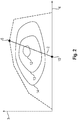
- FIG 2 a monotonically increasing operating characteristic 2 is shown in a consumption diagram.
- the operating characteristic 2 along which the internal combustion engine is operated extends from the first operating point 5 at a first speed with maximum power output 3 to a second operating point 15 at a second speed with minimum power output 3.
- the operating characteristic in this example is continuously linear and increases in a strictly monotonous manner .
- the first speed is lower than the second speed and the power output 3 increases linearly with the speed 4.
- the operating characteristic curve 2 runs through the region of the innermost consumption characteristic curve 12 in which the specific fuel consumption is particularly low. This operating characteristic curve 2 enables particularly efficient operation of the internal combustion engine.
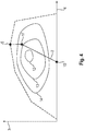
- FIG 3 a vertical operating characteristic 2 is shown in a consumption diagram.
- the following are just the differences too Figure 1 explained.
- the operating characteristic line 2 along which the internal combustion engine is operated extends from a third operating point 16 at the first speed with minimum power output to the first operating point 5 at the first speed with maximum power output.
- the operating curve 2 is vertical in this example.
- the speed 4 is identical at all points of the operating characteristic 2. This operating characteristic 2 enables particularly comfortable operation of the internal combustion engine and, thanks to the constant speed, ensures a constant quality of work.
- a monotonically increasing operating characteristic 2 with a vertical section is shown in a consumption diagram.
- the operating characteristic 2 combines a vertical section in the area of high power output with a linearly increasing section in the area of low power output.
- the operating characteristic 2 extends from the first operating point 5 at the first speed with maximum power output via a fourth operating point 17 at the first speed with medium power output to the second operating point 15 at the second speed with minimum power output.
- a monotonically increasing operating characteristic 2 with several vertical sections is shown in a consumption diagram.
- the operating characteristic 2 extends from the first operating point 5 at the first speed with maximum power output via the fourth operating point 17 at the first speed and the medium power output, a fifth operating point 18 at a third speed and the same power output as at the fourth operating point 17, one sixth operating point 19 at the third speed with low power output, a seventh operating point 20 at the second speed and the same power output as at the sixth operating point 19 to the second operating point 15 at the second speed with minimal power output.
- the third speed is lower than the first speed and higher than the second speed.
- This operating curve 2 combines the comfort on the vertical sections with an efficient course through the area of the lowest specific consumption.
- FIG 6 a monotonically increasing operating characteristic 2 with several vertical sections and an inclined section is shown in a consumption diagram.
- the operating characteristic extends from the first operating point 5 at the first speed with maximum power output via the fourth operating point 17 at the first speed and the average power output, the fifth operating point 18 at the third speed and the same power output as at the fourth operating point 17, the sixth Operating point 19 at the third speed with low power output to the second operating point 15 at the second speed with minimal power output.
- This operating characteristic combines the comfort on the vertical Sections with an efficient course through the area of the lowest specific consumption.
- a self-propelled harvesting machine 7 is shown in the form of a forage harvester.
- the self-propelled harvesting machine 7 is driven through a field 21, for example a corn field.
- a crop flow 22 made up of plant parts is drawn in through a feed channel 23 during operation and fed to a working element 9, here a chopping drum, for the purpose of further comminution.
- the self-propelled harvesting machine 7 furthermore comprises a travel drive 10 with a drive axle for drive wheels (not shown).
- the self-propelled harvesting machine 7 has an internal combustion engine 1.
- the internal combustion engine 1 serves both to drive the traction drive 10 and, at the same time, to drive various work organs 9 divides.
- the first partial drive train 25 is provided for transmitting drive power from the internal combustion engine 1 to the working element 9.
- the second partial drive train 26 is provided for transmitting drive power to the travel drive 10.
- control unit 8 is also shown. At least one operating characteristic 2 is stored in control unit 8.
- the stored operating characteristic 2 can, for example, be one of the Figures 2 to 6 operating characteristics 2 shown.
- the control unit 8 controls the internal combustion engine 1 along the stored operating characteristic curve 2.
- a speed and / or torque sensor is provided on the drive train 24.
- the operator can select one of the operating characteristics via an input device 28.
- the self-propelled harvesting machine comprises an electric motor 11 in addition to the internal combustion engine 1.
- the electric motor 11 is connected to the drive train 12 via a third partial drive train 27 and can support or load the internal combustion engine 1.
- the electric motor 11 is connected to an energy store 29.
- the electric motor 11 can draw energy from the energy store 29 in order to support the internal combustion engine 1 and when under load of the internal combustion engine 1 store energy in the energy store 29.
- the control device 8 is connected to the electric motor 11 and controls whether and how much the electric motor 11 supports or loads the internal combustion engine 1.
- the electric motor 11 delivers torque to the drive train 12 and thus supports the internal combustion engine 1 , until the internal combustion engine 1 has reached an operating point at which the power output of the internal combustion engine 1 corresponds to the power requirement. If the power requirement falls and the speed 4 on the drive train 12 increases, since the power output of the internal combustion engine 1 is greater, i.e. the power requirement, the electric motor 11 loads the drive train 12 until the internal combustion engine 1 has reached an operating point at which the power output of the internal combustion engine 1 corresponds to the power requirement.
Abstract
Description
- Die Erfindung betrifft ein Verfahren zur Ansteuerung eines Verbrennungsmotors, wobei der Verbrennungsmotor entlang einer vorbestimmten Betriebskennlinie betrieben wird,
Eine Ansteuerung eines Verbrennungsmotors ist aus derDE102008020497A1 bekannt. Dabei wird der Verbrennungsmotor entlang der Vollastkennlinie betrieben und Lastschwankungen mit einem Hilfsaggregat ausgeglichen, um den Verbrennungsmotor in einem gewählten Betriebspunkt zu halten. - Problematisch an der Ansteuerung ist, dass der Verbrennungsmotor dauerhaft auf der Volllastkennlinie betrieben wird.
- Aufgabe der Erfindung ist es ein verbessertes Ansteuerungsverfahren für einen Verbrennungsmotor, insbesondere für einen Verbrennungsmotor in einer Selbstfahrenden Erntemaschine, anzugeben.
- Gelöst wird die Aufgabe durch ein Verfahren zur Ansteuerung eines Verbrennungsmotors, wobei der Verbrennungsmotor entlang einer vorbestimmten Betriebskennlinie betrieben wird, wobei die Leistungsabgabe des Verbrennungsmotors entlang der Betriebskennlinie monoton mit der Drehzahl ansteigt, wobei die Betriebskennlinie mit Ausnahme des Betriebspunktes mit maximaler Leistungsabgabe unterhalb der Vollastkennlinie liegt.
- Da die Leistungsabgabe des Verbrennungsmotors entlang der Betriebskennlinie monoton mit der Drehzahl ansteigt, ist die Leistungsabgabe bei einer ersten Drehzahl mindestens so hoch wie bei einer zweiten Drehzahl, wenn die erste Drehzahl höher ist als die zweite Drehzahl. Bei steigender Drehzahl fällt die Leistungsabgabe also niemals ab. Bei der kleinstmöglichen Leistungsabgabe ist die Drehzahl damit nicht größer als bei der größtmöglichen Leistungsabgabe. Bevorzugt ist bei der kleinstmöglichen Leistungsabgabe die Drehzahl kleiner als bei der größtmöglichen Leistungsabgabe. Die Leistungsabgabe kann auch bei gleichbleibender Drehzahl steigen oder fallen, dies entspricht einer unendlichen Steigung der Betriebskennlinie.
- Der Betrieb entlang einer vorbestimmten Betriebskennlinie bedeutet nicht, dass der Verbrennungsmotor niemals Betriebspunkte außerhalb der vorbestimmten Betriebskennlinie erreicht. Durch äußere Einflüsse kann sich der Betriebspunkt des Verbrennungsmotors von der vorbestimmten Betriebskennlinie lösen, der Verbrennungsmotor wird jedoch immer wieder auf die vorbestimmte Betriebskennlinie zurück geregelt. Bspw. kann ein plötzlicher Lastanstieg den Verbrennungsmotor abbremsen, dann wird die Leistungsabgabe des Motors gesteigert und dadurch der Verbrennungsmotor beschleunigt bis der Betriebspunkt wieder auf der vorbestimmten Betriebskennlinie liegt. Bei sinkender Last wird die Drehzahl des Verbrennungsmotors steigen, dann wird die Leistungsabgabe des Motors gedrosselt, sodass die Drehzahl des Verbrennungsmotors wieder sinkt, bis der Betriebspunkt wieder auf der vorbestimmten Betriebskennlinie liegt.
- Eine monoton steigende Betriebskennlinie ermöglicht einen komfortablen Betrieb. Eine Betriebskennlinie, die zum größten Teil unterhalb der Volllastkennlinie liegt ermöglicht einen effizienten Betrieb des Verbrennungsmotors.
- Bevorzugt verläuft die vorbestimmte Betriebskennlinie zumindest abschnittsweise linear. Eine lineare Betriebskennlinie ermöglicht eine besonders einfache Regelung.
- Bevorzugt verläuft die vorbestimmte Betriebskennlinie zumindest abschnittsweise senkrecht. Eine senkrechte Betriebskennlinie bedeutet eine gleichbleibende Drehzahl bei schwankender Leistungsabgabe. Dies ermöglicht einen besonders komfortablen Betrieb, insbesondere für selbstfahrende Erntemaschinen.
- Besonders bevorzugt weist die Betriebskennlinie bei der höchsten Drehzahl der Betriebskennlinie einen senkrechten Abschnitt auf. Im Bereich der höchsten Leistungsabgabe und damit der höchsten Drehzahl, da die Betriebskennlinie monoton ansteigt, ist ein komfortabler Betrieb und damit eine gleichbleibende Drehzahl bei schwankender Leistungsabgabe besonders wünschenswert.
- Bevorzugt steigt die vorbestimmte Betriebskennlinie unterhalb der höchsten Drehzahl streng monoton an. Eine streng monoton ansteigende Betriebskennlinie bedeutet, dass die Leistungsabgabe bei einer ersten Drehzahl höher ist als bei einer zweiten Drehzahl, wenn die erste Drehzahl höher ist als die zweite Drehzahl. Eine streng monoton steigende Betriebskennlinie ermöglicht insbesondere bei stark schwankenden Leistungsanforderungen eine einfache und effiziente Regelung.
- Bevorzugt wird die vorbestimmte Betriebskennlinie aus einer Vielzahl an Betriebskennlinien ausgewählt. Die Betriebskennlinien können unterschiedliche Anforderungen erfüllen. Je nach Betriebssituation kann aus der Vielzahl an Betriebskennlinien die passende ausgewählt werden.
- Bevorzugt erfolgt die Auswahl in Abhängigkeit einer Eingabe vom Bediener. In einer Ausgestaltung wählt der Bediener direkt die gewünschte Betriebskennlinie aus. In einer alternativen Ausgestaltung wählt der Bediener gewünschte Anforderungen ein Steuergerät wählt daraufhin die passende Betriebskennlinie aus.
- Besonders bevorzugt erfolgt die Auswahl automatisch in Abhängigkeit einer Betriebssituation. Bei der Auswahl kann die Betriebssituation aus verschiedenen Sensorwerten bestimmt werden. Bspw. kann über einen Schichthöhensensor die Menge des zu verarbeitenden Ernteguts erkannt werden. Bei einer großen Menge Erntegut wird bevorzugt eine Betriebskennlinie gewählt, die für eine gleichbleibende Arbeitsqualität sorgt. Bei einer kleinen Menge Erntegut wird eine Betriebskennlinie gewählt, die für einen besonders effizienten Betrieb sorgt.
- Die Erfindung betrifft ferner eine selbstfahrende Erntemaschine mit einem Verbrennungsmotor und einem Steuergerät, wobei das Steuergerät dazu vorgesehen und eingerichtet ist den Verbrennungsmotor gemäß einem der vorstehend beschriebenen Verfahren zu betreiben. Eine selbstfahrende Erntemaschine wird durch das Verfahren zur Ansteuerung des Verbrennungsmotors besonders komfortabel und effizient betrieben.
- Bevorzugt umfasst die selbstfahrende Erntemaschine zumindest ein Arbeitsorgan und einen Fahrantrieb und der Verbrennungsmotor ist dazu vorgesehen und eingerichtet sowohl den Fahrantrieb als auch das Arbeitsorgan mit Energie zu versorgen. Der Verbrennungsmotor ist sowohl mit dem Fahrantrieb als auch mit dem Arbeitsorgan verbunden und in der Lage sowohl den Fahrantrieb als auch das Arbeitsorgan mit Energie zu versorgen. Dadurch wird nur der Verbrennungsmotor als Energiequelle für beide Verbraucher benötigt.
- Bevorzugt umfasst die selbstfahrende Erntemaschine einen Elektromotor, wobei der Elektromotor dazu vorgesehen und eingerichtet ist den Verbrennungsmotor je nach Ansteuerung des Elektromotors zu unterstützen oder zu belasten. Vorteilhaft ist der Elektromotor mit einem Energiespeicher verbunden. Der Elektromotor kann Energie aus dem Energiespeicher entnehmen und Energie an den Energiespeicher abgeben. Steigt der Leistungsbedarf, so ist der Elektromotor in der Lage die zusätzliche Leistung aufzubringen bis der Verbrennungsmotor auf einen Betriebspunkt eingestellt ist, in dem er den Leistungsbedarf decken kann. Vorteilhaft kann der Elektromotor auch Energie in den Energiespeicher einbringen. Sinkt der Leistungsbedarf, so ist der Elektromotor in der Lage vom Verbrennungsmotor abgegebene aber von Fahrantrieb und Arbeitsorgan nicht benötigte Energie umzuwandeln und in dem Energiespeicher zu lagern. Der Energiespeicher kann bspw. als Kondensator, Akkumulator oder kinetischer Energiespeicher ausgestaltet sein. Der Elektromotor ist dadurch in der Lage die Ansteuerung des Verbrennungsmotors zu verbessern.
- In einer Ausgestaltung ist die Arbeitsgeschwindigkeit des zumindest einen Arbeitsorgans an die Drehzahl des Verbrennungsmotors gekoppelt. Eine Kopplung der Arbeitsgeschwindigkeit des zumindest einen Arbeitsorgans an die Drehzahl des Verbrennungsmotors kann bspw. über eine mechanische Verbindung zwischen Verbrennungsmotor und Arbeitsorgan gegeben sein. Eine solche Verbindung ist häufig sehr effizient in der Energieübertragung. Eine schwankende Arbeitsgeschwindigkeit des Arbeitsorgans ist allerdings häufig schlecht für das Arbeitsergebnis. Eine gleichbleibende Drehzahl bewirkt in dieser Ausgestaltung eine gleichbleibende Arbeitsgeschwindigkeit des Arbeitsorgans und damit ein gleichbleibend gutes Arbeitsergebnis. Eine gleichbleibende Drehzahl wird insbesondere durch eine hohe Steigung der Betriebskennlinie oder eine senkrechte Betriebskennlinie erreicht. Eine gleichbleibende Arbeitsgeschwindigkeit und damit eine gleichbleibende Drehzahl des Verbrennungsmotors ist insbesondere bei einer hohen Leistungsanforderung und damit einer hohen Leistungsabgabe des Verbrennungsmotors vorteilhaft.
- Bevorzugt ist die Fahrgeschwindigkeit der selbstfahrenden Erntemaschine von der Drehzahl des Verbrennungsmotors unabhängig. Eine Unabhängigkeit der Fahrgeschwindigkeit von der Drehzahl des Verbrennungsmotors lässt sich bspw. über eine verstellbare hydraulische Kupplung erreichen. Über die verstellbare hydraulische Kupplung kann die vom Verbrennungsmotor an den Fahrantrieb übertragene Leistung unabhängig von der Drehzahl und der Leistungsabgabe des Verbrennungsmotors eingestellt werden. Bei einer selbstfahrenden Erntemaschine bestimmt die Fahrgeschwindigkeit im allgemeinen wie viel Erntegut von der Erntemaschine aufgenommen wird und von den Arbeitsorganen verarbeitet werden muss und damit den Leistungsbedarf der Arbeitsorgane. Durch die von der Drehzahl des Verbrennungsmotors unabhängig einstellbare Fahrgeschwindigkeit lässt sich also die benötigte Leistungsabgabe des Verbrennungsmotors beeinflussen.
- Im Folgenden wird die Erfindung an Ausführungsbeispielen näher erläutert. Dabei zeigt
-
Figur 1 ein Verbrauchsdiagramm eines Verbrennungsmotors, -
Figur 2 eine monoton steigende Betriebskennlinie in einem Verbrauchsdiagramm, -
Figur 3 eine vertikale Betriebskennlinie in einem Verbrauchsdiagramm, -
Figur 4 eine monoton steigende Betriebskennlinie mit einem vertikalen Abschnitt, -
Figur 5 eine selbstfahrende Erntemaschine. - In
Figur 1 ist ein vereinfachtes Verbrauchsdiagramm eines beispielhaften Verbrennungsmotors dargestellt. Auf der waagerechten Achse ist dabei die Drehzahl 4 des Verbrennungsmotors aufgetragen. Dabei steigt die Drehzahl 4 von links nach rechts an. Auf der senkrechten Achse ist die Leistungsabgabe 3 des Verbrennungsmotors aufgetragen. Dabei steigt die Leistungsabgabe 3 von unten nach oben an. Die möglichen Betriebspunkte des Verbrennungsmotors werden durch die Volllastkennlinie 6 begrenzt. Die Volllastkennlinie 6 gibt an wie groß die Leistungsabgabe 3 des Verbrennungsmotors bei einer bestimmten Drehzahl 4 maximal sein kann. Auf der Volllastkennlinie befindet sich ein erster Betriebspunkt 5 mit der maximalen Leistungsabgabe des Verbrennungsmotors. Die Verbrauchskennlinien 12, 13, 14 verbinden Betriebspunkte mit gleichen spezifischen Kraftstoffverbrauches. Dabei ist der spezifische Kraftstoffverbrauch im Allgemeinen in der Nähe der Volllastkennlinie 3 größer als im inneren Bereich des Verbrauchsdiagramms. Im inneren Bereich der innersten Verbrauchskennlinie 12 arbeitet der Verbrennungsmotor am effizientesten, da dort der spezifische Kraftstoffverbrauch des Verbrennungsmotors am niedrigsten ist. - In
Figur 2 ist eine monoton steigende Betriebskennlinie 2 in einem Verbrauchsdiagramm dargestellt. Im Folgenden werden nur die Unterschiede zuFigur 1 erläutert. Die Betriebskennlinie 2 entlang derer der Verbrennungsmotor betrieben wird erstreckt sich von dem ersten Betriebspunkt 5 bei einer ersten Drehzahl mit maximaler Leistungsabgabe 3 zu einem zweiten Betriebspunkt 15 bei einer zweiten Drehzahl mit minimaler Leistungsabgabe 3. Die Betriebskennlinie ist in diesem Beispiel durchgehend linear und streng monoton steigend. Die erste Drehzahl ist kleiner als die zweite Drehzahl und die Leistungsabgabe 3 steigt mit der Drehzahl 4 linear an. Die Betriebskennlinie 2 geht durch den Bereich der innersten Verbrauchskennlinie 12 in der der spezifische Kraftstoffverbrauch besonders niedrig ist. Diese Betriebskennlinie 2 ermöglicht einen besonders effizienten Betrieb des Verbrennungsmotors. - In
Figur 3 ist eine vertikale Betriebskennlinie 2 in einem Verbrauchsdiagramm dargestellt. Im Folgenden werden nur die Unterschiede zuFigur 1 erläutert. Die Betriebskennlinie 2 entlang derer der Verbrennungsmotor betrieben wird erstreckt sich von einem dritten Betriebspunkt 16 bei der ersten Drehzahl mit minimaler Leistungsabgabe zu dem ersten Betriebspunkt 5 bei der ersten Drehzahl mit maximaler Leistungsabgabe. Die Betriebskennlinie 2 ist in diesem Beispiel vertikal. Die Drehzahl 4 ist an allen Punkten der Betriebskennlinie 2 identisch. Diese Betriebskennlinie 2 ermöglicht einen besonders komfortablen Betrieb des Verbrennungsmotors und sorgt durch die gleichbleibende Drehzahl für eine gleichbleibende Arbeitsqualität. - In
Figur 4 ist eine monoton steigende Betriebskennlinie 2 mit einem vertikalen Abschnitt in einem Verbrauchsdiagramm dargestellt. Die Betriebskennlinie 2 kombiniert einen senkrechten Abschnitt im Bereich hoher Leistungsabgabe mit einem linear steigenden Abschnitt im Bereich niedriger Leistungsabgabe. Die Betriebskennlinie 2 erstreckt sich von dem ersten Betriebspunkt 5 bei der ersten Drehzahl mit maximaler Leistungsabgabe über einen vierten Betriebspunkt 17 bei der ersten Drehzahl mit mittlerer Leistungsabgabe zu dem zweiten Betriebspunkt 15 bei der zweiten Drehzahl mit minimaler Leistungsabgabe. - In
Figur 5 ist eine monoton steigende Betriebskennlinie 2 mit mehreren vertikalen Abschnitten in einem Verbrauchsdiagramm dargestellt. Die Betriebskennlinie 2 erstreckt sich von dem ersten Betriebspunkt 5 bei der ersten Drehzahl mit maximaler Leistungsabgabe über den vierten Betriebspunkt 17 bei der ersten Drehzahl und der mittleren Leistungsabgabe, einen fünften Betriebspunkt 18 bei einer dritten Drehzahl und der gleichen Leistungsabgabe wie am vierten Betriebspunkt 17, einen sechsten Betriebspunkt 19 bei der dritten Drehzahl mit geringer Leistungsabgabe, einen siebten Betriebspunkt 20 bei der zweiten Drehzahl und der gleichen Leistungsabgabe wie am sechsten Betriebspunkt 19 zu dem zweiten Betriebspunkt 15 bei der zweiten Drehzahl mit minimaler Leistungsabgabe. Die dritte Drehzahl ist dabei geringer als die erste Drehzahl und größer als die zweite Drehzahl. Diese Betriebskennlinie 2 kombiniert den Komfort auf den senkrechten Abschnitten mit einem effizienten Verlauf durch den Bereich des niedrigsten spezifischen Verbrauchs. - In
Figur 6 ist eine monoton steigende Betriebskennlinie 2 mit mehreren vertikalen Abschnitten und einem schräg ansteigenden Abschnitt in einem Verbrauchsdiagramm dargestellt. Die Betriebskennlinie erstreckt sich von dem ersten Betriebspunkt 5 bei der ersten Drehzahl mit maximaler Leistungsabgabe über den vierten Betriebspunkt 17 bei der ersten Drehzahl und der mittleren Leistungsabgabe, den fünften Betriebspunkt 18 bei der dritten Drehzahl und der gleichen Leistungsabgabe wie am vierten Betriebspunkt 17, den sechsten Betriebspunkt 19 bei der dritten Drehzahl mit geringer Leistungsabgabe zu dem zweiten Betriebspunkt 15 bei der zweiten Drehzahl mit minimaler Leistungsabgabe. Diese Betriebskennlinie kombiniert den Komfort auf den senkrechten Abschnitten mit einem effizienten Verlauf durch den Bereich des niedrigsten spezifischen Verbrauchs. - In
Figur 7 ist eine selbstfahrende Erntemaschine 7 in Form eines Feldhäckslers dargestellt. Die selbstfahrende Erntemaschine 7 wird durch einen Feldbestand 21, bspw. ein Maisfeld, gefahren. Ein Gutfluss 22 aus Pflanzenteilen wird während des Betriebs durch einen Einzugskanal 23 eingezogen und zum Zwecke der weiteren Zerkleinerung einem Arbeitsorgan 9, hier einer Häckslertrommel, zugeführt. Weiterhin umfasst die selbstfahrende Erntemaschine 7 einen Fahrantrieb 10 mit einer Antriebsachse für Antriebsräder (nicht dargestellt). - Außerdem verfügt die selbstfahrende Erntemaschine 7 über einen Verbrennungsmotor 1. Der Verbrennungsmotor 1 dient sowohl zum Antrieb des Fahrantriebs 10 als auch, und zwar gleichzeitig, zum Antrieb verschiedener Arbeitsorgane 9. Dazu ist ein Antriebsstrang 24 vorgesehen, der sich in zumindest zwei Teilantriebsstränge 25, 26 aufteilt. Der erste Teilantriebsstrang 25 ist zum Übertragen von Antriebsleistung des Verbrennungsmotors 1 an das Arbeitsorgan 9 vorgesehen. Der zweite Teilantriebsstrang 26 ist zum Übertragen von Antriebsleistung an den Fahrantrieb 10 vorgesehen.
- In
Figur 7 ist außerdem ein Steuergerät 8 dargestellt. In dem Steuergerät 8 ist zumindest eine Betriebskennlinie 2 hinterlegt. Die hinterlegte Betriebskennlinie 2 kann bspw. eine der in denFiguren 2 bis 6 dargestellten Betriebskennlinien 2 sein. Das Steuergerät 8 steuert den Verbrennungsmotor 1 entlang der hinterlegten Betriebskennlinie 2. Dazu ist ein Drehzahl- und/oder Drehmomentsensor am Antriebsstrang 24 vorgesehen. - Sind auf dem Steuergerät 8 mehrere Betriebskennlinien 2 hinterlegt, so kann der Bediener über ein Eingabgegerät 28 eine der Betriebskennlinien auswählen.
- In der dargestellten Ausführungsform umfasst die selbstfahrende Erntemaschine neben dem Verbrennungsmotor 1 einen Elektromotor 11. Der Elektromotor 11 ist über einen dritten Teilantriebsstrang 27 mit dem Antriebsstrang 12 verbunden und kann den Verbrennungsmotor 1 unterstützen oder belasten. Der Elektromotor 11 ist mit einem Energiespeicher 29 verbunden. Der Elektromotor 11 kann aus dem Energiespeicher 29 Energie entnehmen, um den Verbrennungsmotor 1 zu unterstützen und bei Belastung des Verbrennungsmotors 1 Energie im Energiespeicher 29 ablegen. Das Steuergerät 8 ist mit dem Elektromotor 11 verbunden und regelt ob und wie stark der Elektromotor 11 den Verbrennungsmotor 1 unterstützt oder belastet. Wenn der Leistungsbedarf steigt, bspw. weil der Feldbestand 21 dichter wird, und dadurch die Drehzahl 4 am Antriebsstrang 12 sinkt, da die Leistungsabgabe des Verbrennungsmotors 1 nicht ausreicht, so gibt der Elektromotor 11 Drehmoment an den Antriebsstrang 12 ab und unterstützt so den Verbrennungsmotor 1, bis der Verbrennungsmotor 1 einen Betriebspunkt erreicht hat, in dem die Leistungsabgabe des Verbrennungsmotors 1 dem Leistungsbedarf entspricht. Wenn der Leistungsbedarf sinkt und dadurch die Drehzahl 4 am Antriebsstrang 12 steigt, da die Leistungsabgabe des Verbrennungsmotors 1 größer ist also der Leistungsbedarf, so belastet der Elektromotor 11 den Antriebsstrang 12 bis der Verbrennungsmotor 1 einen Betriebspunkt erreicht hat, in dem die Leistungsabgabe des Verbrennungsmotors 1 dem Leistungsbedarf entspricht.
-
- 1
- Verbrennungsmotor
- 2
- Betriebskennlinie
- 3
- Leistungsabgabe
- 4
- Drehzahl
- 5
- Erster Betriebspunkt mit maximaler Leistungsabgabe
- 6
- Volllastkennlinie
- 7
- Selbstfahrende Erntemaschine
- 8
- Steuergerät
- 9
- Arbeitsorgan
- 10
- Fahrantrieb
- 11
- Elektromotor
- 12-14
- Verbrauchskennlinien
- 15
- Zweiter Betriebspunkt mit der minimaler Leistungsabgabe
- 16
- Dritter Betriebspunkt mit minimaler Leistungsabgabe
- 17-20
- Betriebspunkte
- 21
- Feldbestand
- 22
- Gutfluss
- 23
- Einzugskanal
- 24
- Antriebsstrang
- 25-27
- Teilantriebsstränge
- 28
- Eingabegerät
- 29
- Energiespeicher
- 30
- Sensor
Claims (13)
- Verfahren zur Ansteuerung eines Verbrennungsmotors (1), wobei der Verbrennungsmotor (1) entlang einer vorbestimmten Betriebskennlinie (2) betrieben wird, dadurch gekennzeichnet, dass die Leistungsabgabe (3) des Verbrennungsmotors (1) entlang der Betriebskennlinie (2) monoton mit der Drehzahl (4) ansteigt, wobei die Betriebskennlinie (2) mit Ausnahme des Betriebspunktes mit maximaler Leistungsabgabe (5) unterhalb der Volllastkennlinie (6) liegt.
- Verfahren nach Anspruch 1, dadurch gekennzeichnet, dass die vorbestimmte Betriebskennlinie (2) zumindest abschnittsweise linear verläuft.
- Verfahren nach Anspruch 2, dadurch gekennzeichnet, dass die vorbestimmte Betriebskennlinie (2) zumindest abschnittsweise senkrecht verläuft.
- Verfahren nach Anspruch 3, dadurch gekennzeichnet, dass die vorbestimmte Betriebskennlinie (2) bei der höchsten Drehzahl der Betriebskennlinie einen senkrechten Abschnitt aufweist.
- Verfahren nach einem der vorhergehenden Ansprüche, dadurch gekennzeichnet, dass die vorbestimmte Betriebskennlinie (2) unterhalb der höchsten Drehzahl streng monoton ansteigt.
- Verfahren nach einem der vorhergehenden Ansprüche, dadurch gekennzeichnet, dass die vorbestimmte Betriebskennlinie (2) aus einer Vielzahl an Betriebskennlinien ausgewählt wird.
- Verfahren nach Anspruch 6, dadurch gekennzeichnet, dass die Auswahl in Abhängigkeit einer Eingabe vom Bediener erfolgt.
- Verfahren nach Anspruch 6, dadurch gekennzeichnet, dass die Auswahl automatisch in Abhängigkeit einer Betriebssituation erfolgt.
- Selbstfahrende Erntemaschine (7) mit einem Verbrennungsmotor (1) und einem Steuergerät (8), wobei das Steuergerät (8) dazu vorgesehen und eingerichtet ist den Verbrennungsmotor (1) gemäß einem Verfahren nach einem der vorhergehenden Ansprüche zu betreiben.
- Selbstfahrende Erntemaschine (7) nach Anspruch 9, dadurch gekennzeichnet, dass die selbstfahrende Erntemaschine (7) zumindest ein Arbeitsorgan (9) und einen Fahrantrieb (10) umfasst und der Verbrennungsmotor (1)) dazu vorgesehen und eingerichtet ist sowohl den Fahrantrieb (10) als auch das Arbeitsorgan (9) mit Energie zu versorgen.
- Selbstfahrende Erntemaschine (7) nach Anspruch 9 oder 10, dadurch gekennzeichnet, dass die selbstfahrende Erntemaschine (7) einen Elektromotor (11) umfasst, wobei der Elektromotor (11) dazu vorgesehen und eingerichtet ist den Verbrennungsmotor (1) je nach Ansteuerung des Elektromotors (11) zu unterstützen oder zu belasten.
- Selbstfahrende Erntemaschine (7) nach einem der Ansprüche 9 bis 11, dadurch gekennzeichnet, dass die Arbeitsgeschwindigkeit des zumindest einen Arbeitsorgans (9) an die Drehzahl (4) des Verbrennungsmotors (1) gekoppelt ist.
- Selbstfahrende Erntemaschine (7) nach einem der Ansprüche 9 bis 12, dadurch gekennzeichnet, dass die Fahrgeschwindigkeit der selbstfahrenden Erntemaschine (7) von der Drehzahl (4) des Verbrennungsmotors (1) unabhängig ist.
Applications Claiming Priority (1)
| Application Number | Priority Date | Filing Date | Title |
|---|---|---|---|
| DE102019116447.8A DE102019116447A1 (de) | 2019-06-18 | 2019-06-18 | Verfahren zur Ansteuerung eines Verbrennungsmotors |
Publications (2)
| Publication Number | Publication Date |
|---|---|
| EP3754172A1 true EP3754172A1 (de) | 2020-12-23 |
| EP3754172B1 EP3754172B1 (de) | 2023-11-08 |
Family
ID=69526039
Family Applications (1)
| Application Number | Title | Priority Date | Filing Date |
|---|---|---|---|
| EP20155837.6A Active EP3754172B1 (de) | 2019-06-18 | 2020-02-06 | Verfahren zur ansteuerung eines verbrennungsmotors |
Country Status (2)
| Country | Link |
|---|---|
| EP (1) | EP3754172B1 (de) |
| DE (1) | DE102019116447A1 (de) |
Cited By (2)
| Publication number | Priority date | Publication date | Assignee | Title |
|---|---|---|---|---|
| CN113494377A (zh) * | 2021-08-17 | 2021-10-12 | 柳州柳工挖掘机有限公司 | 一种电控发动机的节能控制方法和工程机械 |
| CN113586273A (zh) * | 2021-08-17 | 2021-11-02 | 柳州柳工挖掘机有限公司 | 一种电控发动机的转速控制方法和工程机械 |
Citations (5)
| Publication number | Priority date | Publication date | Assignee | Title |
|---|---|---|---|---|
| US20040088103A1 (en) * | 2002-10-29 | 2004-05-06 | Koichiro Itow | Engine control device |
| DE102008020497A1 (de) | 2008-04-23 | 2009-11-05 | Claas Selbstfahrende Erntemaschinen Gmbh | Betriebsverfahren für einen Verbrennungsmotor |
| EP2223588A2 (de) * | 2009-02-27 | 2010-09-01 | Deere & Company | Selbstfahrende Erntemaschine |
| WO2011026807A1 (en) * | 2009-09-01 | 2011-03-10 | Cnh Belgium N.V. | Agricultural machine with variable rpm control |
| EP3257353A1 (de) * | 2016-06-14 | 2017-12-20 | CLAAS Selbstfahrende Erntemaschinen GmbH | Landwirtschaftliche arbeitsmaschine und verfahren zum betrieb einer landwirtschaftlichen arbeitsmaschine |
-
2019
- 2019-06-18 DE DE102019116447.8A patent/DE102019116447A1/de active Pending
-
2020
- 2020-02-06 EP EP20155837.6A patent/EP3754172B1/de active Active
Patent Citations (5)
| Publication number | Priority date | Publication date | Assignee | Title |
|---|---|---|---|---|
| US20040088103A1 (en) * | 2002-10-29 | 2004-05-06 | Koichiro Itow | Engine control device |
| DE102008020497A1 (de) | 2008-04-23 | 2009-11-05 | Claas Selbstfahrende Erntemaschinen Gmbh | Betriebsverfahren für einen Verbrennungsmotor |
| EP2223588A2 (de) * | 2009-02-27 | 2010-09-01 | Deere & Company | Selbstfahrende Erntemaschine |
| WO2011026807A1 (en) * | 2009-09-01 | 2011-03-10 | Cnh Belgium N.V. | Agricultural machine with variable rpm control |
| EP3257353A1 (de) * | 2016-06-14 | 2017-12-20 | CLAAS Selbstfahrende Erntemaschinen GmbH | Landwirtschaftliche arbeitsmaschine und verfahren zum betrieb einer landwirtschaftlichen arbeitsmaschine |
Cited By (4)
| Publication number | Priority date | Publication date | Assignee | Title |
|---|---|---|---|---|
| CN113494377A (zh) * | 2021-08-17 | 2021-10-12 | 柳州柳工挖掘机有限公司 | 一种电控发动机的节能控制方法和工程机械 |
| CN113586273A (zh) * | 2021-08-17 | 2021-11-02 | 柳州柳工挖掘机有限公司 | 一种电控发动机的转速控制方法和工程机械 |
| CN113494377B (zh) * | 2021-08-17 | 2022-06-28 | 柳州柳工挖掘机有限公司 | 一种电控发动机的节能控制方法和工程机械 |
| CN113586273B (zh) * | 2021-08-17 | 2023-09-12 | 柳州柳工挖掘机有限公司 | 一种电控发动机的转速控制方法和工程机械 |
Also Published As
| Publication number | Publication date |
|---|---|
| EP3754172B1 (de) | 2023-11-08 |
| DE102019116447A1 (de) | 2020-12-24 |
Similar Documents
| Publication | Publication Date | Title |
|---|---|---|
| EP3298876B1 (de) | Feldhäcksler | |
| EP2112357B1 (de) | Betriebsverfahren für einen Verbrennungsmotor | |
| EP1946631B1 (de) | Landwirtschaftliche Arbeitsmaschine | |
| EP0901928A2 (de) | Selbstfahrende Arbeitsmaschine | |
| EP3754172B1 (de) | Verfahren zur ansteuerung eines verbrennungsmotors | |
| EP2057881A2 (de) | Motorregelung einer selbstfahrenden Arbeitsmaschine | |
| EP3259975B1 (de) | Landwirtschaftliche arbeitsmaschine und verfahren zum betrieb einer landwirtschaftlichen arbeitsmaschine | |
| DE102018104287A1 (de) | Feldhäcksler und Verfahren zum Betreiben eines Feldhäckslers | |
| EP3326446B1 (de) | Geschwindigkeitskontrolle einer erntemaschine | |
| DE102004056233A1 (de) | Landwirtschaftliche Arbeitsmaschine mit einem Antriebsmotor | |
| DE102013110315A1 (de) | Landwirtschaftliche Arbeitsmaschine | |
| EP3300584B1 (de) | Landwirtschaftliche arbeitsmaschine und verfahren zum betrieb einer landwirtschaftlichen arbeitsmaschine | |
| EP3760027B1 (de) | Antriebssystem für eine erntemaschine | |
| DE102010003940A1 (de) | Antriebssystem eines Nutzfahrzeugs und Verfahren zur Steuerung eines Antriebssystems eines Nutzfahrzeugs | |
| DE102019132547A1 (de) | Zugmaschine | |
| DE102019123947A1 (de) | Selbstfahrender Feldhäcksler sowie Verfahren zur Ernte mittels eines Feldhäckslers | |
| DE102008043677A1 (de) | Antriebssystem eines Nutzfahrzeuges und Verfahren zur Steuerung eines Antriebssystems eines Nutzfahrzeuges | |
| EP3888443A1 (de) | Landwirtschaftliche arbeitsmaschine | |
| DE19705841A1 (de) | Regelung der Gebläsedrehzahl der Reinigungsvorrichtung eines Mähdreschers | |
| EP3459331B1 (de) | Landwirtschaftliche arbeitsmaschine | |
| DE102007053036A1 (de) | Steuer- und/oder Regeleinrichtung sowie Verfahren | |
| EP4272537A1 (de) | Selbstfahrende landwirtschaftliche arbeitsmaschine | |
| DE10319628B4 (de) | Fahrzeug-Steuerungs- und/oder Regelungsverfahren einer Steuerung eines Fahrzeuges mit einem stufenlos verstellbaren Getriebe | |
| WO2023078975A1 (de) | Fahrantriebssystem und verfahren zum betreiben eines fahrantriebssystems | |
| DE102020112451A1 (de) | Landwirtschaftliche Arbeitsmaschine |
Legal Events
| Date | Code | Title | Description |
|---|---|---|---|
| PUAI | Public reference made under article 153(3) epc to a published international application that has entered the european phase |
Free format text: ORIGINAL CODE: 0009012 |
|
| STAA | Information on the status of an ep patent application or granted ep patent |
Free format text: STATUS: THE APPLICATION HAS BEEN PUBLISHED |
|
| AK | Designated contracting states |
Kind code of ref document: A1 Designated state(s): AL AT BE BG CH CY CZ DE DK EE ES FI FR GB GR HR HU IE IS IT LI LT LU LV MC MK MT NL NO PL PT RO RS SE SI SK SM TR |
|
| AX | Request for extension of the european patent |
Extension state: BA ME |
|
| STAA | Information on the status of an ep patent application or granted ep patent |
Free format text: STATUS: REQUEST FOR EXAMINATION WAS MADE |
|
| 17P | Request for examination filed |
Effective date: 20210623 |
|
| RBV | Designated contracting states (corrected) |
Designated state(s): AL AT BE BG CH CY CZ DE DK EE ES FI FR GB GR HR HU IE IS IT LI LT LU LV MC MK MT NL NO PL PT RO RS SE SI SK SM TR |
|
| GRAP | Despatch of communication of intention to grant a patent |
Free format text: ORIGINAL CODE: EPIDOSNIGR1 |
|
| STAA | Information on the status of an ep patent application or granted ep patent |
Free format text: STATUS: GRANT OF PATENT IS INTENDED |
|
| P01 | Opt-out of the competence of the unified patent court (upc) registered |
Effective date: 20230516 |
|
| INTG | Intention to grant announced |
Effective date: 20230614 |
|
| GRAS | Grant fee paid |
Free format text: ORIGINAL CODE: EPIDOSNIGR3 |
|
| GRAA | (expected) grant |
Free format text: ORIGINAL CODE: 0009210 |
|
| STAA | Information on the status of an ep patent application or granted ep patent |
Free format text: STATUS: THE PATENT HAS BEEN GRANTED |
|
| AK | Designated contracting states |
Kind code of ref document: B1 Designated state(s): AL AT BE BG CH CY CZ DE DK EE ES FI FR GB GR HR HU IE IS IT LI LT LU LV MC MK MT NL NO PL PT RO RS SE SI SK SM TR |
|
| REG | Reference to a national code |
Ref country code: GB Ref legal event code: FG4D Free format text: NOT ENGLISH |
|
| REG | Reference to a national code |
Ref country code: CH Ref legal event code: EP |
|
| REG | Reference to a national code |
Ref country code: DE Ref legal event code: R096 Ref document number: 502020005912 Country of ref document: DE |
|
| REG | Reference to a national code |
Ref country code: IE Ref legal event code: FG4D Free format text: LANGUAGE OF EP DOCUMENT: GERMAN |
|
| REG | Reference to a national code |
Ref country code: LT Ref legal event code: MG9D |
|
| REG | Reference to a national code |
Ref country code: NL Ref legal event code: MP Effective date: 20231108 |
|
| PG25 | Lapsed in a contracting state [announced via postgrant information from national office to epo] |
Ref country code: GR Free format text: LAPSE BECAUSE OF FAILURE TO SUBMIT A TRANSLATION OF THE DESCRIPTION OR TO PAY THE FEE WITHIN THE PRESCRIBED TIME-LIMIT Effective date: 20240209 |
|
| PG25 | Lapsed in a contracting state [announced via postgrant information from national office to epo] |
Ref country code: IS Free format text: LAPSE BECAUSE OF FAILURE TO SUBMIT A TRANSLATION OF THE DESCRIPTION OR TO PAY THE FEE WITHIN THE PRESCRIBED TIME-LIMIT Effective date: 20240308 |
|
| PG25 | Lapsed in a contracting state [announced via postgrant information from national office to epo] |
Ref country code: LT Free format text: LAPSE BECAUSE OF FAILURE TO SUBMIT A TRANSLATION OF THE DESCRIPTION OR TO PAY THE FEE WITHIN THE PRESCRIBED TIME-LIMIT Effective date: 20231108 |
|
| PG25 | Lapsed in a contracting state [announced via postgrant information from national office to epo] |
Ref country code: NL Free format text: LAPSE BECAUSE OF FAILURE TO SUBMIT A TRANSLATION OF THE DESCRIPTION OR TO PAY THE FEE WITHIN THE PRESCRIBED TIME-LIMIT Effective date: 20231108 |