EP3753752A1 - Pneumatic tire - Google Patents
Pneumatic tire Download PDFInfo
- Publication number
- EP3753752A1 EP3753752A1 EP19754115.4A EP19754115A EP3753752A1 EP 3753752 A1 EP3753752 A1 EP 3753752A1 EP 19754115 A EP19754115 A EP 19754115A EP 3753752 A1 EP3753752 A1 EP 3753752A1
- Authority
- EP
- European Patent Office
- Prior art keywords
- tire
- tread portion
- tread
- range
- height
- Prior art date
- Legal status (The legal status is an assumption and is not a legal conclusion. Google has not performed a legal analysis and makes no representation as to the accuracy of the status listed.)
- Granted
Links
Images
Classifications
-
- B—PERFORMING OPERATIONS; TRANSPORTING
- B60—VEHICLES IN GENERAL
- B60C—VEHICLE TYRES; TYRE INFLATION; TYRE CHANGING; CONNECTING VALVES TO INFLATABLE ELASTIC BODIES IN GENERAL; DEVICES OR ARRANGEMENTS RELATED TO TYRES
- B60C11/00—Tyre tread bands; Tread patterns; Anti-skid inserts
- B60C11/03—Tread patterns
- B60C11/0306—Patterns comprising block rows or discontinuous ribs
-
- B—PERFORMING OPERATIONS; TRANSPORTING
- B60—VEHICLES IN GENERAL
- B60C—VEHICLE TYRES; TYRE INFLATION; TYRE CHANGING; CONNECTING VALVES TO INFLATABLE ELASTIC BODIES IN GENERAL; DEVICES OR ARRANGEMENTS RELATED TO TYRES
- B60C11/00—Tyre tread bands; Tread patterns; Anti-skid inserts
-
- B—PERFORMING OPERATIONS; TRANSPORTING
- B60—VEHICLES IN GENERAL
- B60C—VEHICLE TYRES; TYRE INFLATION; TYRE CHANGING; CONNECTING VALVES TO INFLATABLE ELASTIC BODIES IN GENERAL; DEVICES OR ARRANGEMENTS RELATED TO TYRES
- B60C11/00—Tyre tread bands; Tread patterns; Anti-skid inserts
- B60C11/0041—Tyre tread bands; Tread patterns; Anti-skid inserts comprising different tread rubber layers
- B60C11/005—Tyre tread bands; Tread patterns; Anti-skid inserts comprising different tread rubber layers with cap and base layers
-
- B—PERFORMING OPERATIONS; TRANSPORTING
- B60—VEHICLES IN GENERAL
- B60C—VEHICLE TYRES; TYRE INFLATION; TYRE CHANGING; CONNECTING VALVES TO INFLATABLE ELASTIC BODIES IN GENERAL; DEVICES OR ARRANGEMENTS RELATED TO TYRES
- B60C11/00—Tyre tread bands; Tread patterns; Anti-skid inserts
- B60C11/0083—Tyre tread bands; Tread patterns; Anti-skid inserts characterised by the curvature of the tyre tread
-
- B—PERFORMING OPERATIONS; TRANSPORTING
- B60—VEHICLES IN GENERAL
- B60C—VEHICLE TYRES; TYRE INFLATION; TYRE CHANGING; CONNECTING VALVES TO INFLATABLE ELASTIC BODIES IN GENERAL; DEVICES OR ARRANGEMENTS RELATED TO TYRES
- B60C11/00—Tyre tread bands; Tread patterns; Anti-skid inserts
- B60C11/03—Tread patterns
- B60C11/0304—Asymmetric patterns
-
- B—PERFORMING OPERATIONS; TRANSPORTING
- B60—VEHICLES IN GENERAL
- B60C—VEHICLE TYRES; TYRE INFLATION; TYRE CHANGING; CONNECTING VALVES TO INFLATABLE ELASTIC BODIES IN GENERAL; DEVICES OR ARRANGEMENTS RELATED TO TYRES
- B60C11/00—Tyre tread bands; Tread patterns; Anti-skid inserts
- B60C11/03—Tread patterns
- B60C11/0327—Tread patterns characterised by special properties of the tread pattern
-
- B—PERFORMING OPERATIONS; TRANSPORTING
- B60—VEHICLES IN GENERAL
- B60C—VEHICLE TYRES; TYRE INFLATION; TYRE CHANGING; CONNECTING VALVES TO INFLATABLE ELASTIC BODIES IN GENERAL; DEVICES OR ARRANGEMENTS RELATED TO TYRES
- B60C11/00—Tyre tread bands; Tread patterns; Anti-skid inserts
- B60C11/03—Tread patterns
- B60C11/0327—Tread patterns characterised by special properties of the tread pattern
- B60C11/0332—Tread patterns characterised by special properties of the tread pattern by the footprint-ground contacting area of the tyre tread
-
- B—PERFORMING OPERATIONS; TRANSPORTING
- B60—VEHICLES IN GENERAL
- B60C—VEHICLE TYRES; TYRE INFLATION; TYRE CHANGING; CONNECTING VALVES TO INFLATABLE ELASTIC BODIES IN GENERAL; DEVICES OR ARRANGEMENTS RELATED TO TYRES
- B60C11/00—Tyre tread bands; Tread patterns; Anti-skid inserts
- B60C11/03—Tread patterns
- B60C11/12—Tread patterns characterised by the use of narrow slits or incisions, e.g. sipes
- B60C11/1272—Width of the sipe
-
- B—PERFORMING OPERATIONS; TRANSPORTING
- B60—VEHICLES IN GENERAL
- B60C—VEHICLE TYRES; TYRE INFLATION; TYRE CHANGING; CONNECTING VALVES TO INFLATABLE ELASTIC BODIES IN GENERAL; DEVICES OR ARRANGEMENTS RELATED TO TYRES
- B60C13/00—Tyre sidewalls; Protecting, decorating, marking, or the like, thereof
-
- B—PERFORMING OPERATIONS; TRANSPORTING
- B60—VEHICLES IN GENERAL
- B60C—VEHICLE TYRES; TYRE INFLATION; TYRE CHANGING; CONNECTING VALVES TO INFLATABLE ELASTIC BODIES IN GENERAL; DEVICES OR ARRANGEMENTS RELATED TO TYRES
- B60C15/00—Tyre beads, e.g. ply turn-up or overlap
- B60C15/0009—Tyre beads, e.g. ply turn-up or overlap features of the carcass terminal portion
- B60C15/0018—Tyre beads, e.g. ply turn-up or overlap features of the carcass terminal portion not folded around the bead core, e.g. floating or down ply
-
- B—PERFORMING OPERATIONS; TRANSPORTING
- B60—VEHICLES IN GENERAL
- B60C—VEHICLE TYRES; TYRE INFLATION; TYRE CHANGING; CONNECTING VALVES TO INFLATABLE ELASTIC BODIES IN GENERAL; DEVICES OR ARRANGEMENTS RELATED TO TYRES
- B60C15/00—Tyre beads, e.g. ply turn-up or overlap
- B60C15/0009—Tyre beads, e.g. ply turn-up or overlap features of the carcass terminal portion
- B60C15/0027—Tyre beads, e.g. ply turn-up or overlap features of the carcass terminal portion with low ply turn-up, i.e. folded around the bead core and terminating at the bead core
-
- B—PERFORMING OPERATIONS; TRANSPORTING
- B60—VEHICLES IN GENERAL
- B60C—VEHICLE TYRES; TYRE INFLATION; TYRE CHANGING; CONNECTING VALVES TO INFLATABLE ELASTIC BODIES IN GENERAL; DEVICES OR ARRANGEMENTS RELATED TO TYRES
- B60C15/00—Tyre beads, e.g. ply turn-up or overlap
- B60C15/06—Flipper strips, fillers, or chafing strips and reinforcing layers for the construction of the bead
-
- B—PERFORMING OPERATIONS; TRANSPORTING
- B60—VEHICLES IN GENERAL
- B60C—VEHICLE TYRES; TYRE INFLATION; TYRE CHANGING; CONNECTING VALVES TO INFLATABLE ELASTIC BODIES IN GENERAL; DEVICES OR ARRANGEMENTS RELATED TO TYRES
- B60C15/00—Tyre beads, e.g. ply turn-up or overlap
- B60C15/06—Flipper strips, fillers, or chafing strips and reinforcing layers for the construction of the bead
- B60C15/0603—Flipper strips, fillers, or chafing strips and reinforcing layers for the construction of the bead characterised by features of the bead filler or apex
-
- B—PERFORMING OPERATIONS; TRANSPORTING
- B60—VEHICLES IN GENERAL
- B60C—VEHICLE TYRES; TYRE INFLATION; TYRE CHANGING; CONNECTING VALVES TO INFLATABLE ELASTIC BODIES IN GENERAL; DEVICES OR ARRANGEMENTS RELATED TO TYRES
- B60C3/00—Tyres characterised by the transverse section
- B60C3/04—Tyres characterised by the transverse section characterised by the relative dimensions of the section, e.g. low profile
-
- B—PERFORMING OPERATIONS; TRANSPORTING
- B60—VEHICLES IN GENERAL
- B60C—VEHICLE TYRES; TYRE INFLATION; TYRE CHANGING; CONNECTING VALVES TO INFLATABLE ELASTIC BODIES IN GENERAL; DEVICES OR ARRANGEMENTS RELATED TO TYRES
- B60C9/00—Reinforcements or ply arrangement of pneumatic tyres
- B60C9/18—Structure or arrangement of belts or breakers, crown-reinforcing or cushioning layers
- B60C9/20—Structure or arrangement of belts or breakers, crown-reinforcing or cushioning layers built-up from rubberised plies each having all cords arranged substantially parallel
- B60C9/2003—Structure or arrangement of belts or breakers, crown-reinforcing or cushioning layers built-up from rubberised plies each having all cords arranged substantially parallel characterised by the materials of the belt cords
- B60C9/2009—Structure or arrangement of belts or breakers, crown-reinforcing or cushioning layers built-up from rubberised plies each having all cords arranged substantially parallel characterised by the materials of the belt cords comprising plies of different materials
-
- B—PERFORMING OPERATIONS; TRANSPORTING
- B60—VEHICLES IN GENERAL
- B60C—VEHICLE TYRES; TYRE INFLATION; TYRE CHANGING; CONNECTING VALVES TO INFLATABLE ELASTIC BODIES IN GENERAL; DEVICES OR ARRANGEMENTS RELATED TO TYRES
- B60C9/00—Reinforcements or ply arrangement of pneumatic tyres
- B60C9/18—Structure or arrangement of belts or breakers, crown-reinforcing or cushioning layers
- B60C9/20—Structure or arrangement of belts or breakers, crown-reinforcing or cushioning layers built-up from rubberised plies each having all cords arranged substantially parallel
- B60C2009/2012—Structure or arrangement of belts or breakers, crown-reinforcing or cushioning layers built-up from rubberised plies each having all cords arranged substantially parallel with particular configuration of the belt cords in the respective belt layers
- B60C2009/2016—Structure or arrangement of belts or breakers, crown-reinforcing or cushioning layers built-up from rubberised plies each having all cords arranged substantially parallel with particular configuration of the belt cords in the respective belt layers comprising cords at an angle of 10 to 30 degrees to the circumferential direction
-
- B—PERFORMING OPERATIONS; TRANSPORTING
- B60—VEHICLES IN GENERAL
- B60C—VEHICLE TYRES; TYRE INFLATION; TYRE CHANGING; CONNECTING VALVES TO INFLATABLE ELASTIC BODIES IN GENERAL; DEVICES OR ARRANGEMENTS RELATED TO TYRES
- B60C11/00—Tyre tread bands; Tread patterns; Anti-skid inserts
- B60C11/0008—Tyre tread bands; Tread patterns; Anti-skid inserts characterised by the tread rubber
- B60C2011/0016—Physical properties or dimensions
-
- B—PERFORMING OPERATIONS; TRANSPORTING
- B60—VEHICLES IN GENERAL
- B60C—VEHICLE TYRES; TYRE INFLATION; TYRE CHANGING; CONNECTING VALVES TO INFLATABLE ELASTIC BODIES IN GENERAL; DEVICES OR ARRANGEMENTS RELATED TO TYRES
- B60C11/00—Tyre tread bands; Tread patterns; Anti-skid inserts
- B60C11/0008—Tyre tread bands; Tread patterns; Anti-skid inserts characterised by the tread rubber
- B60C2011/0016—Physical properties or dimensions
- B60C2011/0025—Modulus or tan delta
-
- B—PERFORMING OPERATIONS; TRANSPORTING
- B60—VEHICLES IN GENERAL
- B60C—VEHICLE TYRES; TYRE INFLATION; TYRE CHANGING; CONNECTING VALVES TO INFLATABLE ELASTIC BODIES IN GENERAL; DEVICES OR ARRANGEMENTS RELATED TO TYRES
- B60C11/00—Tyre tread bands; Tread patterns; Anti-skid inserts
- B60C11/03—Tread patterns
- B60C2011/0337—Tread patterns characterised by particular design features of the pattern
- B60C2011/0339—Grooves
-
- B—PERFORMING OPERATIONS; TRANSPORTING
- B60—VEHICLES IN GENERAL
- B60C—VEHICLE TYRES; TYRE INFLATION; TYRE CHANGING; CONNECTING VALVES TO INFLATABLE ELASTIC BODIES IN GENERAL; DEVICES OR ARRANGEMENTS RELATED TO TYRES
- B60C11/00—Tyre tread bands; Tread patterns; Anti-skid inserts
- B60C11/03—Tread patterns
- B60C2011/0337—Tread patterns characterised by particular design features of the pattern
- B60C2011/0339—Grooves
- B60C2011/0381—Blind or isolated grooves
-
- B—PERFORMING OPERATIONS; TRANSPORTING
- B60—VEHICLES IN GENERAL
- B60C—VEHICLE TYRES; TYRE INFLATION; TYRE CHANGING; CONNECTING VALVES TO INFLATABLE ELASTIC BODIES IN GENERAL; DEVICES OR ARRANGEMENTS RELATED TO TYRES
- B60C11/00—Tyre tread bands; Tread patterns; Anti-skid inserts
- B60C11/03—Tread patterns
- B60C11/12—Tread patterns characterised by the use of narrow slits or incisions, e.g. sipes
- B60C11/1204—Tread patterns characterised by the use of narrow slits or incisions, e.g. sipes with special shape of the sipe
- B60C2011/1213—Tread patterns characterised by the use of narrow slits or incisions, e.g. sipes with special shape of the sipe sinusoidal or zigzag at the tread surface
-
- B—PERFORMING OPERATIONS; TRANSPORTING
- B60—VEHICLES IN GENERAL
- B60C—VEHICLE TYRES; TYRE INFLATION; TYRE CHANGING; CONNECTING VALVES TO INFLATABLE ELASTIC BODIES IN GENERAL; DEVICES OR ARRANGEMENTS RELATED TO TYRES
- B60C11/00—Tyre tread bands; Tread patterns; Anti-skid inserts
- B60C11/03—Tread patterns
- B60C11/12—Tread patterns characterised by the use of narrow slits or incisions, e.g. sipes
- B60C11/1236—Tread patterns characterised by the use of narrow slits or incisions, e.g. sipes with special arrangements in the tread pattern
- B60C2011/1254—Tread patterns characterised by the use of narrow slits or incisions, e.g. sipes with special arrangements in the tread pattern with closed sipe, i.e. not extending to a groove
-
- B—PERFORMING OPERATIONS; TRANSPORTING
- B60—VEHICLES IN GENERAL
- B60C—VEHICLE TYRES; TYRE INFLATION; TYRE CHANGING; CONNECTING VALVES TO INFLATABLE ELASTIC BODIES IN GENERAL; DEVICES OR ARRANGEMENTS RELATED TO TYRES
- B60C11/00—Tyre tread bands; Tread patterns; Anti-skid inserts
- B60C11/03—Tread patterns
- B60C11/12—Tread patterns characterised by the use of narrow slits or incisions, e.g. sipes
- B60C2011/129—Sipe density, i.e. the distance between the sipes within the pattern
-
- B—PERFORMING OPERATIONS; TRANSPORTING
- B60—VEHICLES IN GENERAL
- B60C—VEHICLE TYRES; TYRE INFLATION; TYRE CHANGING; CONNECTING VALVES TO INFLATABLE ELASTIC BODIES IN GENERAL; DEVICES OR ARRANGEMENTS RELATED TO TYRES
- B60C13/00—Tyre sidewalls; Protecting, decorating, marking, or the like, thereof
- B60C2013/005—Physical properties of the sidewall rubber
- B60C2013/007—Thickness
-
- B—PERFORMING OPERATIONS; TRANSPORTING
- B60—VEHICLES IN GENERAL
- B60C—VEHICLE TYRES; TYRE INFLATION; TYRE CHANGING; CONNECTING VALVES TO INFLATABLE ELASTIC BODIES IN GENERAL; DEVICES OR ARRANGEMENTS RELATED TO TYRES
- B60C15/00—Tyre beads, e.g. ply turn-up or overlap
- B60C15/0009—Tyre beads, e.g. ply turn-up or overlap features of the carcass terminal portion
- B60C2015/009—Height of the carcass terminal portion defined in terms of a numerical value or ratio in proportion to section height
-
- B—PERFORMING OPERATIONS; TRANSPORTING
- B60—VEHICLES IN GENERAL
- B60C—VEHICLE TYRES; TYRE INFLATION; TYRE CHANGING; CONNECTING VALVES TO INFLATABLE ELASTIC BODIES IN GENERAL; DEVICES OR ARRANGEMENTS RELATED TO TYRES
- B60C15/00—Tyre beads, e.g. ply turn-up or overlap
- B60C15/06—Flipper strips, fillers, or chafing strips and reinforcing layers for the construction of the bead
- B60C15/0603—Flipper strips, fillers, or chafing strips and reinforcing layers for the construction of the bead characterised by features of the bead filler or apex
- B60C2015/061—Dimensions of the bead filler in terms of numerical values or ratio in proportion to section height
-
- Y—GENERAL TAGGING OF NEW TECHNOLOGICAL DEVELOPMENTS; GENERAL TAGGING OF CROSS-SECTIONAL TECHNOLOGIES SPANNING OVER SEVERAL SECTIONS OF THE IPC; TECHNICAL SUBJECTS COVERED BY FORMER USPC CROSS-REFERENCE ART COLLECTIONS [XRACs] AND DIGESTS
- Y02—TECHNOLOGIES OR APPLICATIONS FOR MITIGATION OR ADAPTATION AGAINST CLIMATE CHANGE
- Y02T—CLIMATE CHANGE MITIGATION TECHNOLOGIES RELATED TO TRANSPORTATION
- Y02T10/00—Road transport of goods or passengers
- Y02T10/80—Technologies aiming to reduce greenhouse gasses emissions common to all road transportation technologies
- Y02T10/86—Optimisation of rolling resistance, e.g. weight reduction
Definitions
- the present invention relates to a pneumatic tire suitable for use on icy and snowy roads and particularly relates to a pneumatic tire capable of improving braking performance on ice and reducing rolling resistance.
- a plurality of longitudinal grooves extending in a tire circumferential direction and a plurality of lateral grooves extending in a tire lateral direction are formed in a tread portion, and a number of blocks are defined by those longitudinal grooves and lateral grooves. Further, a plurality of sipes are formed in each of the blocks.
- the pneumatic tire as described above can exert excellent driving performance on ice and snow with the grooves and the sipes formed in the tread portion. In recent years, it has been further demanded to improve braking performance on ice.
- the pneumatic tire for use on icy and snowy roads adopts a multilayer structure including a cap tread rubber layer and an undertread rubber layer for the tread portion.
- the flexible cap tread rubber layer exerts followability with respect to a road surface, and at the same time, the undertread rubber layer functioning as a foundation contributes to improvement in steering stability (for example, see Patent Documents 1 and 2).
- a rubber composition forming the undertread rubber layer has high tan ⁇ .
- rolling resistance is likely to be degraded.
- An object of the present invention is to provide a pneumatic tire capable of improving braking performance on ice and reducing rolling resistance.
- a pneumatic tire according to the present invention includes: a tread portion extending in a tire circumferential direction and having an annular shape, a pair of sidewall portions disposed on both sides of the tread portion, and a pair of bead portions disposed inward of the pair of sidewall portions in a tire radial direction, wherein a carcass layer is mounted between the pair of bead portions, the tread portion has a multilayer structure including a cap tread rubber layer and an undertread rubber layer, grooves and sipes are formed in the tread portion, a snow traction index STI based on the grooves and sipes is 180 or more, a tread radius in a meridian cross-section of the tread portion falls within a range of from 80% to 140% of a tire outer diameter, a ground contact width of the tread portion falls within a range of from 66% to 83% of a tire cross-sectional width, and a height of a bead filler disposed on an outer
- a flat tread profile is adopted, and the ground contact width of the tread portion is increased.
- a ground contact area of the tread portion can be increased, and braking performance on ice can be improved.
- the height of the bead filler is reduced.
- a vertical spring constant of the tire is reduced, and the side wall portion is likely to be deflected.
- an energy loss in the tread portion can be relatively reduced, and rolling resistance can be reduced.
- a ground contact area at the time of braking is increased.
- this also contributes to improvement in braking performance on ice. With this, braking performance on ice can be improved, and rolling resistance can be reduced.
- a tire maximum width position preferably falls within a range of from 50% to 60% of the tire cross-sectional height.
- a vertical spring constant of the tire is reduced, and the side wall portion is likely to be deflected.
- an energy loss in the tread portion can be relatively reduced, and rolling resistance can be reduced. Further, deflection of the sidewall portion increases a ground contact area.
- a rubber thickness at the tire maximum width position on an outer side of the carcass layer preferably falls within a range of from 1 mm to 4 mm.
- a vertical spring constant of the tire is reduced, and a ground contact area is increased. Further, an energy loss in the side wall portion can be reduced, and rolling resistance can be reduced.
- the carcass layer is preferably turned up around the bead core from an inner side to an outer side of the tire, and a turned-up height of the carcass layer falls within a range of from 10% to 40% of the tire cross-sectional height.
- a vertical spring constant of the tire can be reduced, a ground contact area can be increased, and rolling resistance can be reduced.
- a snow traction index STI is set to 180 or more.
- the snow traction index STI is calculated with Expression (1) given below.
- STI ⁇ 6.8 + 2202 ⁇ g + 672 ⁇ s + 7.6 Dg .
- ps: sipe density (mm/mm 2 ) a total length of extending components of the sipes in the tire lateral direction (mm)/a total area of a ground contact region (mm 2 )
- Dg Average groove depth (mm).
- the dimensions such as the tread radius, the tire outer diameter, and the tire cross-sectional height are measured under a state in which the tire is mounted on a regular rim and inflated to a regular internal pressure.
- the tire ground contact width of the tread portion is the ground contact width in the tire axial direction measured under a state in which the tire is mounted on a regular rim and inflated to a regular internal pressure and when placed vertically upon a flat surface with a regular load applied thereto.
- Regular rim is a rim defined by a standard for each tire according to a system of standards that includes standards on which tires are based and refers to a "standard rim” in the case of JATMA, refers to a "design rim” in the case of TRA, and refers to a “measuring rim” in the case of ETRTO.
- Regular internal pressure is air pressure defined by a standard for each tire according to a system of standards that includes standards on which tires are based and refers to "maximum air pressure” in the case of JATMA, refers to the maximum value in the table of "TIRE ROAD LIMITS AT VARIOUS COLD INFLATION PRESSURES" in the case of TRA, and refers to "INFLATION PRESSURE” in the case of ETRTO.
- regular internal pressure is 180 kPa in a case where a tire is a tire for a passenger vehicle.
- Regular load is a load defined by a standard for each tire according to a system of standards that includes standards on which the tires are based and refers to "maximum load capacity" in the case of JATMA, refers to the maximum value in the table of "TIRE ROAD LIMITS AT VARIOUS COLD INFLATION PRESSURES" in the case of TRA, and refers to "LOAD CAPACITY" in the case of ETRTO.
- maximum load capacity in the case of JATMA
- TIRE ROAD LIMITS AT VARIOUS COLD INFLATION PRESSURES refers to "LOAD CAPACITY" in the case of ETRTO.
- FIG. 1 and FIG. 2 illustrate a pneumatic tire according to an embodiment of the present invention.
- Tc indicates a tire circumferential direction
- Tw indicates a tire lateral direction
- CL indicates a tire equator
- TCW indicates a ground contact width.
- a pneumatic tire of the present embodiment includes a tread portion 1 having an annular shape and extending in the tire circumferential direction, a pair of sidewall portions 2, 2 disposed on both sides of the tread portion 1, and a pair of bead portions 3, 3 disposed inward of the sidewall portions 2 in the tire radial direction.
- a carcass layer 4 is mounted between the pair of bead portions 3, 3.
- the carcass layer 4 includes a plurality of reinforcing cords extending in the tire radial direction and is folded back around bead cores 5 disposed in each of the bead portions 3 from a tire inner side to a tire outer side.
- a bead filler 6 having a triangular cross-sectional shape formed from rubber composition is disposed on the outer circumference of the bead core 5.
- a plurality of belt layers 7 are embedded on the outer circumferential side of the carcass layer 4 in the tread portion 1.
- the belt layers 7 each include a plurality of reinforcing cords that are inclined with respect to the tire circumferential direction, the reinforcing cords being disposed between layers in a criss-cross manner.
- the inclination angle of the reinforcing cords with respect to the tire circumferential direction falls within a range of from 10° to 40°, for example.
- Steel cords are preferably used as the reinforcing cords of the belt layers 7.
- At least one belt cover layer 8 formed by arranging reinforcing cords at an angle of, for example, not greater than 5° with respect to the tire circumferential direction, is disposed on an outer circumferential side of the belt layers 7.
- Nylon, aramid, or similar organic fiber cords are preferably used as the reinforcing cords of the belt cover layer 8.
- a cap tread rubber layer 11A and an undertread rubber layer 11B are disposed on an outer side of the carcass layer 4, the belt layers 7, and the belt cover layer 8 in the tread portion 1.
- the cap tread rubber layer 11A is positioned outward of the undertread rubber layer 11B in the tire radial direction and is exposed to a tire outer surface.
- the undertread rubber layer 11B is formed of a rubber composition having hardness higher than a rubber composition forming the cap tread rubber layer 11A. More specifically, the rubber composition forming the cap tread rubber layer 11A has JIS hardness falling within a range of from 50 to 65, and the rubber composition forming the undertread rubber layer 11B has JIS hardness falling within a range of from 56 to 66.
- the JIS hardness is the durometer hardness measured in accordance with JIS K-6253 using a type A durometer and under a temperature of 20°C.
- a side rubber layer 12 is disposed on an outer side of the carcass layer 4 in the sidewall portion 2.
- a rim cushion rubber layer 13 is disposed on the outer side of the carcass layer 4 in the bead portion 3.
- an innerliner layer 14 is disposed along the carcass layer 4.
- a plurality of longitudinal grooves 21 extending in the tire circumferential direction Tc and a plurality of lateral grooves 22 extending in the tire lateral direction Tw are formed in the tread portion 1.
- a plurality of land portions 23 each having a block shape are defined by those longitudinal grooves 21 and lateral grooves 22 in the tread portion 1.
- a plurality of sipes 24 extending in the tire lateral direction are formed.
- the sipe may extend in a zigzag shape or may extend linearly along the tire lateral direction.
- the sipe 24 has a groove width of approximately 1.5 mm or less.
- the tread pattern is not particularly limited.
- a snow traction index STI is set to 180 or more, more preferably, falls within a range of from 180 to 240.
- a tread radius TR in the meridian cross-section of the tread portion 1 is set to fall within a range of from 80% to 140% of a tire outer diameter OD
- the ground contact width TCW of the tread portion 1 is set to fall within a range of from 66% to 83% of a tire cross-sectional width SW
- a height BFH of the bead filler 6 disposed on an outer circumference of the bead core 5 of the bead portion 3 is set to fall within a range of 40% or less of a tire cross-sectional height SH.
- a flat tread profile defined by the tread radius TR is adopted, and the ground contact width TCW of the tread portion 1 is increased.
- a ground contact area of the tread portion 1 can be increased, and braking performance on ice can be improved.
- the height BFH of the bead filler 6 is reduced.
- a vertical spring constant of the tire is reduced, and the side wall portion 2 is likely to be deflected.
- an energy loss in the tread portion 1 can be relatively reduced, and rolling resistance can be reduced.
- a ground contact area at the time of braking is increased.
- this also contributes to improvement in braking performance on ice.
- braking performance on ice can be improved, and rolling resistance can be reduced.
- the tread radius TR in the meridian cross-section of the tread portion 1 is less than 80% of the tire outer diameter OD, a ground contact area is insufficient. In contrast, when the tread radius TR is more than 140%, contact with the ground in a center region is degraded. Thus, an effect of improving braking performance on ice is lowered.
- the tread radius TR preferably falls within a range of from 110% to 130% of the tire outer diameter OD.
- the ground contact width TCW of the tread portion 1 when the ground contact width TCW of the tread portion 1 is less than 66% of the tire cross-sectional width SW, a ground contact area is insufficient. In contrast, when the ground contact width TCW is more than 83%, contact with the ground is improved in shoulder regions but degraded in the center region. Thus, an effect of improving braking performance on ice is lowered.
- the ground contact width TCW of the tread portion 1 preferably falls within a range of from 70% to 80% of the tire cross-sectional width SW.
- the height BFH of the bead filler 6 when the height BFH of the bead filler 6 is more than 40% of the tire cross-sectional height SH, an effect of reducing rolling resistance cannot be obtained. Particularly, the height BFH of the bead filler 6 preferably falls within a range of from 10% to 20% of the tire cross-sectional height SH. Note that the height BFH of the bead filler 6 may be 0% of the tire cross-sectional height SH (that is, a structure without the bead filler 6).
- a height Hmax from a bead heel position to a tire maximum width position Pmax in the tire radial direction preferably falls within a range of from 50% to 60% of the tire cross-sectional height SH.
- a vertical spring constant of the tire is reduced, and the side wall portion 2 is likely to be deflected.
- an energy loss in the tread portion 1 can be relatively reduced, and rolling resistance can be reduced.
- a ground contact area can be increased.
- the height Hmax from the bead heal position to the tire maximum width position Pmax in the tire radial direction preferably falls within a range of from 52% to 56% of the tire cross-sectional height SH.
- a rubber thickness T at the tire maximum width position Pmax on an outer side of the carcass layer 4 preferably falls within a range of from 1 mm to 4 mm.
- a vertical spring constant of the tire is reduced, and a ground contact area is increased.
- an energy loss in the side wall portion 2 can be reduced, and rolling resistance can be reduced.
- the rubber thickness T is less than 1 mm, cut resistance is degraded.
- the rubber thickness T is more than 4 mm, an energy loss in the side wall portion 2 is increased.
- the rubber thickness T preferably falls within a range of from 2 mm to 3 mm.
- the carcass layer 4 is turned up around the bead core 5 from an inner side to an outer side of the tire, a turned-up height TUH of the carcass layer 4 falls within a range of from 10% to 40% of the tire cross-sectional height SH.
- a vertical spring constant of the tire can be reduced, a ground contact area can be increased, and rolling resistance can be reduced.
- the turned-up height TUH of the carcass layer 4 is less than 10% of the tire cross-sectional height SH, rigidity around the bead portion 3 is insufficient.
- the turned-up height TUH is more than 40%, an effect of reducing a vertical spring constant is lowered.
- the turned-up height TUH of the carcass layer 4 preferably falls within a range of from 20% to 30% of the tire cross-sectional height SH.
- each of the tires had a tire size of 205/60 R16 and included: a tread portion, a pair of sidewall portions, and a pair of bead portions, in which a carcass layer was mounted between the pair of bead portions, and the tread portion had a multilayer structure including a cap tread rubber layer and an undertread rubber layer, and in which grooves and sipes are formed in the tread portion, and a snow traction index STI based on those grooves and sipes was set 186 or more, a ratio of the tread radius TR with respect to the tire outer diameter OD (TR/OD ⁇ 100%), a ratio of the ground contact width TCW with respect to the tire cross-sectional width SW (TCW/SW ⁇ 100%), a ratio of the bead filler height BFH with respect to the tire cross-sectional height SH (BFH/SH ⁇ 100%), the height Hmax at the tire maximum width position Pmax with respect to the tire cross-sectional height SH (Hmax/SH ⁇ 100%).
- Each of the test tires was assembled on a wheel with a rim size of 16 ⁇ 6.0 J, mounted on a front wheel drive vehicle having an engine displacement of 1500 cc, and inflated to an air pressure of 180 kPa.
- a braking distance was measured after performing ABS braking from a traveling condition at a speed of 20 km/h on a test course formed of an icy road surface under a load equivalent to two passengers.
- the evaluation results were expressed, using the reciprocal of the measured values, as index values with the value of the Conventional Example being defined as 100. Larger index values indicate superior braking performance on ice.
- Each of the test tires was assembled on a wheel having a rim size of 16 ⁇ 6.0 J, and mounted on a rolling resistance tester, and pre-running was performed for 30 minutes under a condition of an air pressure of 230 kPa, a load of 4.5 kN, and a speed of 80 km/h. Then, rolling resistance was measured under the same conditions. The evaluation results were expressed, using the reciprocal of the measurement values, as index values with the value of the Conventional Example being defined as 100. Higher index values indicate lower rolling resistance.
- the tires in Examples 1 to 10 was capable of improving braking performance on ice and reducing rolling resistance as compared to Conventional Example.
- the tires in Comparative Examples 1 to 4 did not satisfy the predetermined dimension requirements, and hence a sufficient effect of improving braking performance on ice could not be obtained.
Landscapes
- Engineering & Computer Science (AREA)
- Mechanical Engineering (AREA)
- Tires In General (AREA)
Abstract
Description
- The present invention relates to a pneumatic tire suitable for use on icy and snowy roads and particularly relates to a pneumatic tire capable of improving braking performance on ice and reducing rolling resistance.
- In general, in a pneumatic tire for use on icy and snowy roads, which is exemplified by a studless tire, a plurality of longitudinal grooves extending in a tire circumferential direction and a plurality of lateral grooves extending in a tire lateral direction are formed in a tread portion, and a number of blocks are defined by those longitudinal grooves and lateral grooves. Further, a plurality of sipes are formed in each of the blocks.
- The pneumatic tire as described above can exert excellent driving performance on ice and snow with the grooves and the sipes formed in the tread portion. In recent years, it has been further demanded to improve braking performance on ice.
- Further, the pneumatic tire for use on icy and snowy roads adopts a multilayer structure including a cap tread rubber layer and an undertread rubber layer for the tread portion. In this case, the flexible cap tread rubber layer exerts followability with respect to a road surface, and at the same time, the undertread rubber layer functioning as a foundation contributes to improvement in steering stability (for example, see
Patent Documents 1 and 2). - However, in general, a rubber composition forming the undertread rubber layer has high tan δ. Thus, when the undertread rubber layer is increased in thickness, rolling resistance is likely to be degraded. In view of this, even though rolling resistance is regarded as a minor problem for the pneumatic tire for use on icy and snowy roads in the related art, it has been demanded to reduce rolling resistance in recent years.
-
- Patent Document 1:
JP 2009-262646 A - Patent Document 2:
JP 2017-140936 A - An object of the present invention is to provide a pneumatic tire capable of improving braking performance on ice and reducing rolling resistance.
- In order to achieve the above-mentioned object, a pneumatic tire according to the present invention includes: a tread portion extending in a tire circumferential direction and having an annular shape, a pair of sidewall portions disposed on both sides of the tread portion, and a pair of bead portions disposed inward of the pair of sidewall portions in a tire radial direction, wherein a carcass layer is mounted between the pair of bead portions, the tread portion has a multilayer structure including a cap tread rubber layer and an undertread rubber layer, grooves and sipes are formed in the tread portion, a snow traction index STI based on the grooves and sipes is 180 or more, a tread radius in a meridian cross-section of the tread portion falls within a range of from 80% to 140% of a tire outer diameter, a ground contact width of the tread portion falls within a range of from 66% to 83% of a tire cross-sectional width, and a height of a bead filler disposed on an outer circumference of a bead core of each of the pair of bead portions is 40% or less of a tire cross-sectional height.
- In the present invention, a flat tread profile is adopted, and the ground contact width of the tread portion is increased. With this, a ground contact area of the tread portion can be increased, and braking performance on ice can be improved. Moreover, the height of the bead filler is reduced. With this, a vertical spring constant of the tire is reduced, and the side wall portion is likely to be deflected. Thus, an energy loss in the tread portion can be relatively reduced, and rolling resistance can be reduced. Further, when deflection of the side wall portion is promoted, a ground contact area at the time of braking is increased. Thus, this also contributes to improvement in braking performance on ice. With this, braking performance on ice can be improved, and rolling resistance can be reduced.
- In the present invention, a tire maximum width position preferably falls within a range of from 50% to 60% of the tire cross-sectional height. When the tire maximum width position is set within the range, a vertical spring constant of the tire is reduced, and the side wall portion is likely to be deflected. Thus, an energy loss in the tread portion can be relatively reduced, and rolling resistance can be reduced. Further, deflection of the sidewall portion increases a ground contact area.
- A rubber thickness at the tire maximum width position on an outer side of the carcass layer preferably falls within a range of from 1 mm to 4 mm. When the rubber thickness at the tire maximum width position on the outer side of the carcass layer is reduced, a vertical spring constant of the tire is reduced, and a ground contact area is increased. Further, an energy loss in the side wall portion can be reduced, and rolling resistance can be reduced.
- The carcass layer is preferably turned up around the bead core from an inner side to an outer side of the tire, and a turned-up height of the carcass layer falls within a range of from 10% to 40% of the tire cross-sectional height. When the turned-up height of the carcass layer is reduced as described above, a vertical spring constant of the tire can be reduced, a ground contact area can be increased, and rolling resistance can be reduced.
- In the present invention, in order to satisfy required characteristics as a pneumatic tire for use on icy and snowy roads, a snow traction index STI is set to 180 or more. The snow traction index STI is calculated with Expression (1) given below.

pg: groove density (mm/mm2) = a total length of extending components of the grooves in the tire lateral direction (mm)/a total area of a ground contact region (mm2),
ps: sipe density (mm/mm2) = a total length of extending components of the sipes in the tire lateral direction (mm)/a total area of a ground contact region (mm2), and
Dg: Average groove depth (mm). - In the present invention, the dimensions such as the tread radius, the tire outer diameter, and the tire cross-sectional height are measured under a state in which the tire is mounted on a regular rim and inflated to a regular internal pressure. Further, the tire ground contact width of the tread portion is the ground contact width in the tire axial direction measured under a state in which the tire is mounted on a regular rim and inflated to a regular internal pressure and when placed vertically upon a flat surface with a regular load applied thereto. "Regular rim" is a rim defined by a standard for each tire according to a system of standards that includes standards on which tires are based and refers to a "standard rim" in the case of JATMA, refers to a "design rim" in the case of TRA, and refers to a "measuring rim" in the case of ETRTO. "Regular internal pressure" is air pressure defined by a standard for each tire according to a system of standards that includes standards on which tires are based and refers to "maximum air pressure" in the case of JATMA, refers to the maximum value in the table of "TIRE ROAD LIMITS AT VARIOUS COLD INFLATION PRESSURES" in the case of TRA, and refers to "INFLATION PRESSURE" in the case of ETRTO. However, "regular internal pressure" is 180 kPa in a case where a tire is a tire for a passenger vehicle. "Regular load" is a load defined by a standard for each tire according to a system of standards that includes standards on which the tires are based and refers to "maximum load capacity" in the case of JATMA, refers to the maximum value in the table of "TIRE ROAD LIMITS AT VARIOUS COLD INFLATION PRESSURES" in the case of TRA, and refers to "LOAD CAPACITY" in the case of ETRTO. When the tire is for use with a passenger vehicle, a load corresponding to 88% of the load described above is used.
-
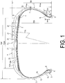
- FIG. 1
- is a meridian cross-sectional view illustrating a pneumatic tire according to an embodiment of the present invention.
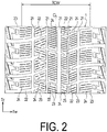
- FIG. 2
- is a developed view illustrating a tread pattern of the pneumatic tire in
FIG. 1 . - Configurations of embodiments of the present invention will be described in detail below with reference to the accompanying drawings.
FIG. 1 andFIG. 2 illustrate a pneumatic tire according to an embodiment of the present invention. InFIG. 1 andFIG. 2 , Tc indicates a tire circumferential direction, Tw indicates a tire lateral direction, CL indicates a tire equator, and TCW indicates a ground contact width. - As illustrated in
FIG. 1 , a pneumatic tire of the present embodiment includes atread portion 1 having an annular shape and extending in the tire circumferential direction, a pair ofsidewall portions tread portion 1, and a pair of bead portions 3, 3 disposed inward of thesidewall portions 2 in the tire radial direction. - A carcass layer 4 is mounted between the pair of bead portions 3, 3. The carcass layer 4 includes a plurality of reinforcing cords extending in the tire radial direction and is folded back around
bead cores 5 disposed in each of the bead portions 3 from a tire inner side to a tire outer side. Abead filler 6 having a triangular cross-sectional shape formed from rubber composition is disposed on the outer circumference of thebead core 5. - A plurality of belt layers 7 are embedded on the outer circumferential side of the carcass layer 4 in the
tread portion 1. The belt layers 7 each include a plurality of reinforcing cords that are inclined with respect to the tire circumferential direction, the reinforcing cords being disposed between layers in a criss-cross manner. In the belt layers 7, the inclination angle of the reinforcing cords with respect to the tire circumferential direction falls within a range of from 10° to 40°, for example. Steel cords are preferably used as the reinforcing cords of the belt layers 7. To improve high-speed durability, at least onebelt cover layer 8, formed by arranging reinforcing cords at an angle of, for example, not greater than 5° with respect to the tire circumferential direction, is disposed on an outer circumferential side of the belt layers 7. Nylon, aramid, or similar organic fiber cords are preferably used as the reinforcing cords of thebelt cover layer 8. - In the pneumatic tire, a cap
tread rubber layer 11A and anundertread rubber layer 11B are disposed on an outer side of the carcass layer 4, the belt layers 7, and thebelt cover layer 8 in thetread portion 1. The captread rubber layer 11A is positioned outward of theundertread rubber layer 11B in the tire radial direction and is exposed to a tire outer surface. Theundertread rubber layer 11B is formed of a rubber composition having hardness higher than a rubber composition forming the captread rubber layer 11A. More specifically, the rubber composition forming the captread rubber layer 11A has JIS hardness falling within a range of from 50 to 65, and the rubber composition forming theundertread rubber layer 11B has JIS hardness falling within a range of from 56 to 66. The JIS hardness is the durometer hardness measured in accordance with JIS K-6253 using a type A durometer and under a temperature of 20°C. - Further, a
side rubber layer 12 is disposed on an outer side of the carcass layer 4 in thesidewall portion 2. A rimcushion rubber layer 13 is disposed on the outer side of the carcass layer 4 in the bead portion 3. Further, on a tire inner surface, aninnerliner layer 14 is disposed along the carcass layer 4. - As illustrated in
FIG. 2 , a plurality oflongitudinal grooves 21 extending in the tire circumferential direction Tc and a plurality oflateral grooves 22 extending in the tire lateral direction Tw are formed in thetread portion 1. A plurality ofland portions 23 each having a block shape are defined by thoselongitudinal grooves 21 andlateral grooves 22 in thetread portion 1. Further, in each of theland portions 23, a plurality ofsipes 24 extending in the tire lateral direction are formed. The sipe may extend in a zigzag shape or may extend linearly along the tire lateral direction. Thesipe 24 has a groove width of approximately 1.5 mm or less. Note that the tread pattern is not particularly limited. In order to satisfy required characteristics as a pneumatic tire for use on icy and snowy roads, a snow traction index STI is set to 180 or more, more preferably, falls within a range of from 180 to 240. - In the pneumatic tire, as illustrated in
FIG. 1 , a tread radius TR in the meridian cross-section of thetread portion 1 is set to fall within a range of from 80% to 140% of a tire outer diameter OD, the ground contact width TCW of thetread portion 1 is set to fall within a range of from 66% to 83% of a tire cross-sectional width SW, and a height BFH of thebead filler 6 disposed on an outer circumference of thebead core 5 of the bead portion 3 is set to fall within a range of 40% or less of a tire cross-sectional height SH. - In the pneumatic tire described above, a flat tread profile defined by the tread radius TR is adopted, and the ground contact width TCW of the
tread portion 1 is increased. With this, a ground contact area of thetread portion 1 can be increased, and braking performance on ice can be improved. Moreover, the height BFH of thebead filler 6 is reduced. With this, a vertical spring constant of the tire is reduced, and theside wall portion 2 is likely to be deflected. Thus, an energy loss in thetread portion 1 can be relatively reduced, and rolling resistance can be reduced. Further, when the deflection of theside wall portion 2 is promoted, a ground contact area at the time of braking is increased. Thus, this also contributes to improvement in braking performance on ice. With this, braking performance on ice can be improved, and rolling resistance can be reduced. - Here, when the tread radius TR in the meridian cross-section of the
tread portion 1 is less than 80% of the tire outer diameter OD, a ground contact area is insufficient. In contrast, when the tread radius TR is more than 140%, contact with the ground in a center region is degraded. Thus, an effect of improving braking performance on ice is lowered. Particularly, the tread radius TR preferably falls within a range of from 110% to 130% of the tire outer diameter OD. - Further, when the ground contact width TCW of the
tread portion 1 is less than 66% of the tire cross-sectional width SW, a ground contact area is insufficient. In contrast, when the ground contact width TCW is more than 83%, contact with the ground is improved in shoulder regions but degraded in the center region. Thus, an effect of improving braking performance on ice is lowered. Particularly, the ground contact width TCW of thetread portion 1 preferably falls within a range of from 70% to 80% of the tire cross-sectional width SW. - Further, when the height BFH of the
bead filler 6 is more than 40% of the tire cross-sectional height SH, an effect of reducing rolling resistance cannot be obtained. Particularly, the height BFH of thebead filler 6 preferably falls within a range of from 10% to 20% of the tire cross-sectional height SH. Note that the height BFH of thebead filler 6 may be 0% of the tire cross-sectional height SH (that is, a structure without the bead filler 6). - In the pneumatic tire, a height Hmax from a bead heel position to a tire maximum width position Pmax in the tire radial direction preferably falls within a range of from 50% to 60% of the tire cross-sectional height SH. When the tire maximum width position Pmax is disposed within the range, a vertical spring constant of the tire is reduced, and the
side wall portion 2 is likely to be deflected. Thus, an energy loss in thetread portion 1 can be relatively reduced, and rolling resistance can be reduced. Further, when theside wall portion 2 is deflected, a ground contact area can be increased. Here, when the tire maximum width position Pmax is positioned inward of a position corresponding to 50% of the tire cross-sectional height SH in the tire radial direction, an effect of reducing a vertical spring constant is lowered. In contrast, when the tire maximum width position Pmax is positioned outward of a position corresponding to 60% of the tire cross-sectional height SH in the tire radial direction, which is not suitable for the tire structure, durability is degraded. Particularly, the height Hmax from the bead heal position to the tire maximum width position Pmax in the tire radial direction preferably falls within a range of from 52% to 56% of the tire cross-sectional height SH. - In the pneumatic tire, a rubber thickness T at the tire maximum width position Pmax on an outer side of the carcass layer 4 preferably falls within a range of from 1 mm to 4 mm. When the rubber thickness T at the tire maximum width position Pmax on the outer side of the carcass layer 4 is reduced, a vertical spring constant of the tire is reduced, and a ground contact area is increased. Further, an energy loss in the
side wall portion 2 can be reduced, and rolling resistance can be reduced. Here, when the rubber thickness T is less than 1 mm, cut resistance is degraded. In contrast, when the rubber thickness T is more than 4 mm, an energy loss in theside wall portion 2 is increased. Particularly, the rubber thickness T preferably falls within a range of from 2 mm to 3 mm. - In the pneumatic tire, the carcass layer 4 is turned up around the
bead core 5 from an inner side to an outer side of the tire, a turned-up height TUH of the carcass layer 4 falls within a range of from 10% to 40% of the tire cross-sectional height SH. When the turned-up height TUH of the carcass layer 4 is reduced as described above, a vertical spring constant of the tire can be reduced, a ground contact area can be increased, and rolling resistance can be reduced. Here, when the turned-up height TUH of the carcass layer 4 is less than 10% of the tire cross-sectional height SH, rigidity around the bead portion 3 is insufficient. In contrast, when the turned-up height TUH is more than 40%, an effect of reducing a vertical spring constant is lowered. Particularly, the turned-up height TUH of the carcass layer 4 preferably falls within a range of from 20% to 30% of the tire cross-sectional height SH. - In a pneumatic tire in which each of the tires had a tire size of 205/60 R16 and included: a tread portion, a pair of sidewall portions, and a pair of bead portions, in which a carcass layer was mounted between the pair of bead portions, and the tread portion had a multilayer structure including a cap tread rubber layer and an undertread rubber layer, and in which grooves and sipes are formed in the tread portion, and a snow traction index STI based on those grooves and sipes was set 186 or more, a ratio of the tread radius TR with respect to the tire outer diameter OD (TR/OD × 100%), a ratio of the ground contact width TCW with respect to the tire cross-sectional width SW (TCW/SW × 100%), a ratio of the bead filler height BFH with respect to the tire cross-sectional height SH (BFH/SH × 100%), the height Hmax at the tire maximum width position Pmax with respect to the tire cross-sectional height SH (Hmax/SH × 100%), the rubber thickness T at the tire maximum width position Pmax, and a ratio of the turned-up height TUH of the carcass layer with respect to the tire cross-sectional height SH (TUH/SH × 100%) were set as shown in Table 1, and tires in Conventional Example, Examples 1 to 10, and Comparative Examples 1 to 4 were produced.
- Braking performance on ice and rolling resistance for these test tires were evaluated according to the following test methods, and the results are shown in Table 1.
- Braking Performance on Ice:
Each of the test tires was assembled on a wheel with a rim size of 16 × 6.0 J, mounted on a front wheel drive vehicle having an engine displacement of 1500 cc, and inflated to an air pressure of 180 kPa. A braking distance was measured after performing ABS braking from a traveling condition at a speed of 20 km/h on a test course formed of an icy road surface under a load equivalent to two passengers. The evaluation results were expressed, using the reciprocal of the measured values, as index values with the value of the Conventional Example being defined as 100. Larger index values indicate superior braking performance on ice. - Rolling Resistance:
Each of the test tires was assembled on a wheel having a rim size of 16 × 6.0 J, and mounted on a rolling resistance tester, and pre-running was performed for 30 minutes under a condition of an air pressure of 230 kPa, a load of 4.5 kN, and a speed of 80 km/h. Then, rolling resistance was measured under the same conditions. The evaluation results were expressed, using the reciprocal of the measurement values, as index values with the value of the Conventional Example being defined as 100. Higher index values indicate lower rolling resistance.[Table 1-3] Conventional Example Comparative Example 1 Example 1 Example 2 Example 3 TR (mm) 550 500 600 1200 1700 TCW/SW × 100% 60 75 75 75 75 BFH/SH × 100% 30 15 15 15 15 Hmax/SH × 100% 45 45 45 45 45 Rubber thickness T (mm) 5 5 5 5 5 Gc/SH × 100% 11 11 11 11 11 Gc/SH × 100% 11 11 11 11 11 TUH/SH × 100% 50 50 50 50 50 Bead core structu re ( FIG. 1 )FIG. 1 FIG. 1 FIG. 1 FIG. 1 Braking performance (index value) 100 100 102 105 102 Rolling resistance (index value) 100 105 105 105 105 [Table 2-3] Comparative Example 2 Comparative Example 3 Example 4 Example 5 Comparative Example 4 TR (mm) 1800 1200 1200 1200 1200 TCW/SW × 100% 75 55 60 90 95 BFH/SH × 100% 15 15 15 15 15 Hmax/SH × 100% 45 45 45 45 45 Rubber thickness T (mm) 5 5 5 5 5 Gc/SH × 100% 11 11 11 11 11 Gc/SH × 100% 11 11 11 11 11 TUH/SH × 100% 50 50 50 50 50 Bead core structu re FIG. 1 FIG. 1 FIG. 1 FIG. 1 FIG. 1 Braking performance (index value) 100 100 102 102 100 Rolling resistance (index value) 105 105 105 105 105 [Table 3-3] Example 6 Example 7 Example 8 Example 9 Example 10 Example 11 Example 12 TR (mm) 1200 1200 1200 1200 1200 1200 1200 TCW/SW × 100% 75 75 75 75 75 75 75 BFH/SH × 100% 10 20 15 15 15 15 0 Hmax/SH × 100% 45 45 55 55 55 55 55 Rubber thickness T (mm) 5 5 5 3 3 3 3 Gc/SH × 100% 11 11 11 11 5 5 5 Gc/SH × 100% 11 11 11 11 5 5 5 TUH/SH × 100% 50 50 50 50 50 25 25 Bead core structu re FIG. 1 FIG. 1 FIG. 1 FIG. 1 FIG. 1 FIG. 1 FIG. 2 Braking performance (index value) 105 105 108 110 115 118 120 Rolling resistance (index value) 108 104 107 110 112 115 117 - As understood from Table 1, the tires in Examples 1 to 10 was capable of improving braking performance on ice and reducing rolling resistance as compared to Conventional Example. In contrast, the tires in Comparative Examples 1 to 4 did not satisfy the predetermined dimension requirements, and hence a sufficient effect of improving braking performance on ice could not be obtained.
-
- 1
- Tread portion
- 2
- Sidewall portion
- 3
- Bead portion
- 4
- Carcass layer
- 5
- Bead core
- 6
- Bead filler
- 7
- Belt layer
- 8
- Belt cover layer
- 11A
- Cap tread rubber layer
- 11B
- Undertread rubber
- 12
- Side rubber layer
- 13
- Rim cushion rubber layer
- 14
- Innerliner layer
- 21
- Longitudinal groove
- 22
- Lateral groove
- 23
- Land portion
- 24
- Sipe
- CL
- Tire equator
Claims (4)
- A pneumatic tire, comprising:a tread portion extending in a tire circumferential direction and having an annular shape;a pair of sidewall portions disposed on both sides of the tread portion; anda pair of bead portions disposed inward of the pair of sidewall portions in a tire radial direction, whereina carcass layer is mounted between the pair of bead portions,
the tread portion has a multilayer structure including a cap tread rubber layer and an undertread rubber layer,
grooves and sipes are formed in the tread portion,
a snow traction index STI based on the grooves and sipes is 180 or more,
a tread radius in a meridian cross-section of the tread portion falls within a range of from 80% to 140% of a tire outer diameter,
a ground contact width of the tread portion falls within a range of from 66% to 83% of a tire cross-sectional width, and
a height of a bead filler disposed on an outer circumference of a bead core of each of the pair of bead portions is 40% or less of a tire cross-sectional height. - The pneumatic tire according to claim 1, wherein
a tire maximum width position falls within a range of from 50% to 60% of the tire cross-sectional height. - The pneumatic tire according to claim 1 or 2, wherein
a rubber thickness at a tire maximum width position on an outer side of the carcass layer falls within a range of from 1 mm to 4 mm. - The pneumatic tire according to any one of claims 1 to 3, wherein
the carcass layer is turned up around the bead core from an inner side to an outer side of the pneumatic tire, and a turned-up height of the carcass layer falls within a range of from 10% to 40% of the tire cross-sectional height.
Applications Claiming Priority (2)
| Application Number | Priority Date | Filing Date | Title |
|---|---|---|---|
| JP2018024354A JP7031348B2 (en) | 2018-02-14 | 2018-02-14 | Pneumatic tires |
| PCT/JP2019/004850 WO2019159892A1 (en) | 2018-02-14 | 2019-02-12 | Pneumatic tire |
Publications (3)
| Publication Number | Publication Date |
|---|---|
| EP3753752A1 true EP3753752A1 (en) | 2020-12-23 |
| EP3753752A4 EP3753752A4 (en) | 2021-11-17 |
| EP3753752B1 EP3753752B1 (en) | 2023-10-04 |
Family
ID=67619320
Family Applications (1)
| Application Number | Title | Priority Date | Filing Date |
|---|---|---|---|
| EP19754115.4A Active EP3753752B1 (en) | 2018-02-14 | 2019-02-12 | Pneumatic tire |
Country Status (7)
| Country | Link |
|---|---|
| US (1) | US20210078367A1 (en) |
| EP (1) | EP3753752B1 (en) |
| JP (1) | JP7031348B2 (en) |
| CN (1) | CN111542440A (en) |
| FI (1) | FI3753752T3 (en) |
| RU (1) | RU2742063C1 (en) |
| WO (1) | WO2019159892A1 (en) |
Families Citing this family (6)
| Publication number | Priority date | Publication date | Assignee | Title |
|---|---|---|---|---|
| CN111361359A (en) * | 2020-05-06 | 2020-07-03 | 正新橡胶(中国)有限公司 | A tire and its casing |
| JP6851579B1 (en) * | 2020-07-28 | 2021-03-31 | 住友ゴム工業株式会社 | Pneumatic tires |
| JP7666097B2 (en) * | 2021-04-22 | 2025-04-22 | 住友ゴム工業株式会社 | tire |
| JP7591985B2 (en) * | 2021-06-30 | 2024-11-29 | 株式会社ブリヂストン | tire |
| CN113895182B (en) * | 2021-11-19 | 2023-08-22 | 四川轮胎橡胶(集团)股份有限公司 | Tire with low rolling resistance and vehicle |
| JP7835984B2 (en) * | 2022-06-24 | 2026-03-26 | 横浜ゴム株式会社 | tire |
Family Cites Families (28)
| Publication number | Priority date | Publication date | Assignee | Title |
|---|---|---|---|---|
| DE3223959A1 (en) * | 1982-06-26 | 1983-12-29 | Continental Gummi-Werke Ag, 3000 Hannover | VEHICLE TIRES FOR WINTER USE |
| JPS61113503A (en) * | 1984-11-06 | 1986-05-31 | Bridgestone Corp | Pneumatic tire for car with good driving stability |
| JP3148938B2 (en) * | 1992-01-24 | 2001-03-26 | 横浜ゴム株式会社 | Pneumatic tire |
| JPH0640220A (en) * | 1992-07-21 | 1994-02-15 | Bridgestone Corp | Pneumatic radial tire |
| JP2966752B2 (en) * | 1995-02-24 | 1999-10-25 | 住友ゴム工業株式会社 | Pneumatic tire |
| JPH10119514A (en) * | 1996-10-17 | 1998-05-12 | Bridgestone Corp | Pneumatic tire |
| JP3410636B2 (en) * | 1997-07-11 | 2003-05-26 | 住友ゴム工業株式会社 | Pneumatic tire |
| JP2002127712A (en) * | 2000-10-27 | 2002-05-08 | Sumitomo Rubber Ind Ltd | Pneumatic tire |
| JP4255229B2 (en) | 2001-11-28 | 2009-04-15 | 住友ゴム工業株式会社 | Pneumatic tire |
| JP2006213193A (en) * | 2005-02-04 | 2006-08-17 | Sumitomo Rubber Ind Ltd | Pneumatic radial tire |
| JP4537890B2 (en) * | 2005-05-20 | 2010-09-08 | 住友ゴム工業株式会社 | Pneumatic radial tire |
| CN101111397B (en) * | 2005-06-17 | 2010-05-19 | 横滨橡胶株式会社 | Pneumatic tire |
| JP2009262646A (en) | 2008-04-22 | 2009-11-12 | Yokohama Rubber Co Ltd:The | Pneumatic tire |
| JP5257185B2 (en) * | 2008-05-19 | 2013-08-07 | 横浜ゴム株式会社 | Pneumatic tire |
| JP5366629B2 (en) * | 2009-04-16 | 2013-12-11 | 株式会社ブリヂストン | Pneumatic tire |
| JP2011057068A (en) * | 2009-09-09 | 2011-03-24 | Yokohama Rubber Co Ltd:The | Pneumatic tire |
| JP4915471B1 (en) * | 2010-11-17 | 2012-04-11 | 横浜ゴム株式会社 | Pneumatic tire |
| JP2012176694A (en) | 2011-02-25 | 2012-09-13 | Bridgestone Corp | Pneumatic radial tire |
| JP2013095233A (en) | 2011-10-31 | 2013-05-20 | Yokohama Rubber Co Ltd:The | Pneumatic tire |
| JP5878384B2 (en) * | 2012-01-30 | 2016-03-08 | 株式会社ブリヂストン | Pneumatic tire |
| JP5469692B2 (en) * | 2012-02-17 | 2014-04-16 | 住友ゴム工業株式会社 | Pneumatic tire |
| JP2014108653A (en) | 2012-11-30 | 2014-06-12 | Yokohama Rubber Co Ltd:The | Pneumatic tire |
| JP5756451B2 (en) * | 2012-12-11 | 2015-07-29 | 住友ゴム工業株式会社 | Pneumatic tire |
| JP5690375B2 (en) * | 2013-06-05 | 2015-03-25 | 株式会社ブリヂストン | tire |
| JP6248537B2 (en) | 2013-10-24 | 2017-12-20 | 横浜ゴム株式会社 | Pneumatic tire |
| JP2015093551A (en) * | 2013-11-11 | 2015-05-18 | 住友ゴム工業株式会社 | Pneumatic tire |
| JP6326399B2 (en) * | 2015-11-27 | 2018-05-16 | 横浜ゴム株式会社 | Pneumatic tire |
| JP2017140936A (en) | 2016-02-10 | 2017-08-17 | 横浜ゴム株式会社 | Pneumatic tire |
-
2018
- 2018-02-14 JP JP2018024354A patent/JP7031348B2/en active Active
-
2019
- 2019-02-12 RU RU2020129104A patent/RU2742063C1/en active
- 2019-02-12 CN CN201980007196.8A patent/CN111542440A/en active Pending
- 2019-02-12 EP EP19754115.4A patent/EP3753752B1/en active Active
- 2019-02-12 WO PCT/JP2019/004850 patent/WO2019159892A1/en not_active Ceased
- 2019-02-12 US US16/970,335 patent/US20210078367A1/en not_active Abandoned
- 2019-02-12 FI FIEP19754115.4T patent/FI3753752T3/en active
Also Published As
| Publication number | Publication date |
|---|---|
| JP7031348B2 (en) | 2022-03-08 |
| FI3753752T3 (en) | 2024-01-03 |
| EP3753752A4 (en) | 2021-11-17 |
| EP3753752B1 (en) | 2023-10-04 |
| WO2019159892A1 (en) | 2019-08-22 |
| JP2019137328A (en) | 2019-08-22 |
| CN111542440A (en) | 2020-08-14 |
| RU2742063C1 (en) | 2021-02-02 |
| US20210078367A1 (en) | 2021-03-18 |
Similar Documents
| Publication | Publication Date | Title |
|---|---|---|
| EP3753752B1 (en) | Pneumatic tire | |
| EP2628612B1 (en) | Pneumatic tire | |
| CN104010836B (en) | Pneumatic radial tire for car and using method thereof | |
| EP2774780B1 (en) | Pneumatic radial tire for passenger car | |
| EP3202596B1 (en) | Run-flat tire | |
| EP3205515A1 (en) | Pneumatic radial tire for passenger vehicle | |
| US20210031570A1 (en) | Pneumatic Tire | |
| US8517071B2 (en) | Pneumatic tire | |
| EP3381719B1 (en) | Pneumatic tire | |
| EP3332991A1 (en) | Pneumatic tire | |
| EP3360699B1 (en) | Heavy duty tire and and method for manufacturing the same | |
| EP3766705B1 (en) | Runflat tire | |
| EP3069899A1 (en) | Pneumatic tire | |
| EP3738794A1 (en) | Studdable tire and pneumatic tire | |
| EP3251876B1 (en) | Pneumatic tire | |
| EP4056385B1 (en) | Pneumatic tire | |
| JP6010987B2 (en) | Pneumatic tire | |
| EP2248682B1 (en) | Studless tire | |
| JP2021075249A (en) | Pneumatic tire | |
| EP4461570A1 (en) | A studded tyre for vehicles | |
| JP2025172580A (en) | tire | |
| JP2025131048A (en) | tire | |
| WO2025248830A1 (en) | Tire | |
| JP2026037612A (en) | tire | |
| JP2025131049A (en) | tire |
Legal Events
| Date | Code | Title | Description |
|---|---|---|---|
| STAA | Information on the status of an ep patent application or granted ep patent |
Free format text: STATUS: THE INTERNATIONAL PUBLICATION HAS BEEN MADE |
|
| PUAI | Public reference made under article 153(3) epc to a published international application that has entered the european phase |
Free format text: ORIGINAL CODE: 0009012 |
|
| STAA | Information on the status of an ep patent application or granted ep patent |
Free format text: STATUS: REQUEST FOR EXAMINATION WAS MADE |
|
| 17P | Request for examination filed |
Effective date: 20200717 |
|
| AK | Designated contracting states |
Kind code of ref document: A1 Designated state(s): AL AT BE BG CH CY CZ DE DK EE ES FI FR GB GR HR HU IE IS IT LI LT LU LV MC MK MT NL NO PL PT RO RS SE SI SK SM TR |
|
| AX | Request for extension of the european patent |
Extension state: BA ME |
|
| DAV | Request for validation of the european patent (deleted) | ||
| DAX | Request for extension of the european patent (deleted) | ||
| A4 | Supplementary search report drawn up and despatched |
Effective date: 20211015 |
|
| RIC1 | Information provided on ipc code assigned before grant |
Ipc: B60C 3/04 20060101ALI20211011BHEP Ipc: B60C 11/12 20060101ALI20211011BHEP Ipc: B60C 11/03 20060101ALI20211011BHEP Ipc: B60C 15/06 20060101ALI20211011BHEP Ipc: B60C 13/00 20060101ALI20211011BHEP Ipc: B60C 11/00 20060101AFI20211011BHEP |
|
| GRAP | Despatch of communication of intention to grant a patent |
Free format text: ORIGINAL CODE: EPIDOSNIGR1 |
|
| STAA | Information on the status of an ep patent application or granted ep patent |
Free format text: STATUS: GRANT OF PATENT IS INTENDED |
|
| RIC1 | Information provided on ipc code assigned before grant |
Ipc: B60C 3/04 20060101ALI20230609BHEP Ipc: B60C 11/12 20060101ALI20230609BHEP Ipc: B60C 11/03 20060101ALI20230609BHEP Ipc: B60C 15/06 20060101ALI20230609BHEP Ipc: B60C 13/00 20060101ALI20230609BHEP Ipc: B60C 11/00 20060101AFI20230609BHEP |
|
| INTG | Intention to grant announced |
Effective date: 20230704 |
|
| GRAS | Grant fee paid |
Free format text: ORIGINAL CODE: EPIDOSNIGR3 |
|
| GRAA | (expected) grant |
Free format text: ORIGINAL CODE: 0009210 |
|
| STAA | Information on the status of an ep patent application or granted ep patent |
Free format text: STATUS: THE PATENT HAS BEEN GRANTED |
|
| AK | Designated contracting states |
Kind code of ref document: B1 Designated state(s): AL AT BE BG CH CY CZ DE DK EE ES FI FR GB GR HR HU IE IS IT LI LT LU LV MC MK MT NL NO PL PT RO RS SE SI SK SM TR |
|
| REG | Reference to a national code |
Ref country code: GB Ref legal event code: FG4D |
|
| REG | Reference to a national code |
Ref country code: CH Ref legal event code: EP |
|
| REG | Reference to a national code |
Ref country code: DE Ref legal event code: R096 Ref document number: 602019038666 Country of ref document: DE |
|
| REG | Reference to a national code |
Ref country code: IE Ref legal event code: FG4D |
|
| P01 | Opt-out of the competence of the unified patent court (upc) registered |
Effective date: 20231005 |
|
| RAP4 | Party data changed (patent owner data changed or rights of a patent transferred) |
Owner name: THE YOKOHAMA RUBBER CO., LTD. |
|
| REG | Reference to a national code |
Ref country code: FI Ref legal event code: FGE |
|
| REG | Reference to a national code |
Ref country code: DE Ref legal event code: R081 Ref document number: 602019038666 Country of ref document: DE Owner name: THE YOKOHAMA RUBBER CO., LTD., HIRATSUKA-SHI, JP Free format text: FORMER OWNER: THE YOKOHAMA RUBBER CO., LTD., TOKYO, JP |
|
| REG | Reference to a national code |
Ref country code: LT Ref legal event code: MG9D |
|
| REG | Reference to a national code |
Ref country code: NL Ref legal event code: MP Effective date: 20231004 |
|
| REG | Reference to a national code |
Ref country code: AT Ref legal event code: MK05 Ref document number: 1617395 Country of ref document: AT Kind code of ref document: T Effective date: 20231004 |
|
| PG25 | Lapsed in a contracting state [announced via postgrant information from national office to epo] |
Ref country code: NL Free format text: LAPSE BECAUSE OF FAILURE TO SUBMIT A TRANSLATION OF THE DESCRIPTION OR TO PAY THE FEE WITHIN THE PRESCRIBED TIME-LIMIT Effective date: 20231004 |
|
| PG25 | Lapsed in a contracting state [announced via postgrant information from national office to epo] |
Ref country code: GR Free format text: LAPSE BECAUSE OF FAILURE TO SUBMIT A TRANSLATION OF THE DESCRIPTION OR TO PAY THE FEE WITHIN THE PRESCRIBED TIME-LIMIT Effective date: 20240105 |
|
| PG25 | Lapsed in a contracting state [announced via postgrant information from national office to epo] |
Ref country code: IS Free format text: LAPSE BECAUSE OF FAILURE TO SUBMIT A TRANSLATION OF THE DESCRIPTION OR TO PAY THE FEE WITHIN THE PRESCRIBED TIME-LIMIT Effective date: 20240204 |
|
| PG25 | Lapsed in a contracting state [announced via postgrant information from national office to epo] |
Ref country code: LT Free format text: LAPSE BECAUSE OF FAILURE TO SUBMIT A TRANSLATION OF THE DESCRIPTION OR TO PAY THE FEE WITHIN THE PRESCRIBED TIME-LIMIT Effective date: 20231004 |
|
| PG25 | Lapsed in a contracting state [announced via postgrant information from national office to epo] |
Ref country code: AT Free format text: LAPSE BECAUSE OF FAILURE TO SUBMIT A TRANSLATION OF THE DESCRIPTION OR TO PAY THE FEE WITHIN THE PRESCRIBED TIME-LIMIT Effective date: 20231004 |
|
| PG25 | Lapsed in a contracting state [announced via postgrant information from national office to epo] |
Ref country code: ES Free format text: LAPSE BECAUSE OF FAILURE TO SUBMIT A TRANSLATION OF THE DESCRIPTION OR TO PAY THE FEE WITHIN THE PRESCRIBED TIME-LIMIT Effective date: 20231004 |
|
| PG25 | Lapsed in a contracting state [announced via postgrant information from national office to epo] |
Ref country code: LT Free format text: LAPSE BECAUSE OF FAILURE TO SUBMIT A TRANSLATION OF THE DESCRIPTION OR TO PAY THE FEE WITHIN THE PRESCRIBED TIME-LIMIT Effective date: 20231004 Ref country code: IS Free format text: LAPSE BECAUSE OF FAILURE TO SUBMIT A TRANSLATION OF THE DESCRIPTION OR TO PAY THE FEE WITHIN THE PRESCRIBED TIME-LIMIT Effective date: 20240204 Ref country code: GR Free format text: LAPSE BECAUSE OF FAILURE TO SUBMIT A TRANSLATION OF THE DESCRIPTION OR TO PAY THE FEE WITHIN THE PRESCRIBED TIME-LIMIT Effective date: 20240105 Ref country code: ES Free format text: LAPSE BECAUSE OF FAILURE TO SUBMIT A TRANSLATION OF THE DESCRIPTION OR TO PAY THE FEE WITHIN THE PRESCRIBED TIME-LIMIT Effective date: 20231004 Ref country code: BG Free format text: LAPSE BECAUSE OF FAILURE TO SUBMIT A TRANSLATION OF THE DESCRIPTION OR TO PAY THE FEE WITHIN THE PRESCRIBED TIME-LIMIT Effective date: 20240104 Ref country code: AT Free format text: LAPSE BECAUSE OF FAILURE TO SUBMIT A TRANSLATION OF THE DESCRIPTION OR TO PAY THE FEE WITHIN THE PRESCRIBED TIME-LIMIT Effective date: 20231004 Ref country code: PT Free format text: LAPSE BECAUSE OF FAILURE TO SUBMIT A TRANSLATION OF THE DESCRIPTION OR TO PAY THE FEE WITHIN THE PRESCRIBED TIME-LIMIT Effective date: 20240205 |
|
| PG25 | Lapsed in a contracting state [announced via postgrant information from national office to epo] |
Ref country code: SE Free format text: LAPSE BECAUSE OF FAILURE TO SUBMIT A TRANSLATION OF THE DESCRIPTION OR TO PAY THE FEE WITHIN THE PRESCRIBED TIME-LIMIT Effective date: 20231004 Ref country code: RS Free format text: LAPSE BECAUSE OF FAILURE TO SUBMIT A TRANSLATION OF THE DESCRIPTION OR TO PAY THE FEE WITHIN THE PRESCRIBED TIME-LIMIT Effective date: 20231004 Ref country code: PL Free format text: LAPSE BECAUSE OF FAILURE TO SUBMIT A TRANSLATION OF THE DESCRIPTION OR TO PAY THE FEE WITHIN THE PRESCRIBED TIME-LIMIT Effective date: 20231004 Ref country code: NO Free format text: LAPSE BECAUSE OF FAILURE TO SUBMIT A TRANSLATION OF THE DESCRIPTION OR TO PAY THE FEE WITHIN THE PRESCRIBED TIME-LIMIT Effective date: 20240104 Ref country code: LV Free format text: LAPSE BECAUSE OF FAILURE TO SUBMIT A TRANSLATION OF THE DESCRIPTION OR TO PAY THE FEE WITHIN THE PRESCRIBED TIME-LIMIT Effective date: 20231004 Ref country code: HR Free format text: LAPSE BECAUSE OF FAILURE TO SUBMIT A TRANSLATION OF THE DESCRIPTION OR TO PAY THE FEE WITHIN THE PRESCRIBED TIME-LIMIT Effective date: 20231004 |
|
| REG | Reference to a national code |
Ref country code: DE Ref legal event code: R097 Ref document number: 602019038666 Country of ref document: DE |
|
| PG25 | Lapsed in a contracting state [announced via postgrant information from national office to epo] |
Ref country code: DK Free format text: LAPSE BECAUSE OF FAILURE TO SUBMIT A TRANSLATION OF THE DESCRIPTION OR TO PAY THE FEE WITHIN THE PRESCRIBED TIME-LIMIT Effective date: 20231004 |
|
| PG25 | Lapsed in a contracting state [announced via postgrant information from national office to epo] |
Ref country code: CZ Free format text: LAPSE BECAUSE OF FAILURE TO SUBMIT A TRANSLATION OF THE DESCRIPTION OR TO PAY THE FEE WITHIN THE PRESCRIBED TIME-LIMIT Effective date: 20231004 |
|
| PG25 | Lapsed in a contracting state [announced via postgrant information from national office to epo] |
Ref country code: SK Free format text: LAPSE BECAUSE OF FAILURE TO SUBMIT A TRANSLATION OF THE DESCRIPTION OR TO PAY THE FEE WITHIN THE PRESCRIBED TIME-LIMIT Effective date: 20231004 |
|
| PG25 | Lapsed in a contracting state [announced via postgrant information from national office to epo] |
Ref country code: SM Free format text: LAPSE BECAUSE OF FAILURE TO SUBMIT A TRANSLATION OF THE DESCRIPTION OR TO PAY THE FEE WITHIN THE PRESCRIBED TIME-LIMIT Effective date: 20231004 Ref country code: SK Free format text: LAPSE BECAUSE OF FAILURE TO SUBMIT A TRANSLATION OF THE DESCRIPTION OR TO PAY THE FEE WITHIN THE PRESCRIBED TIME-LIMIT Effective date: 20231004 Ref country code: RO Free format text: LAPSE BECAUSE OF FAILURE TO SUBMIT A TRANSLATION OF THE DESCRIPTION OR TO PAY THE FEE WITHIN THE PRESCRIBED TIME-LIMIT Effective date: 20231004 Ref country code: IT Free format text: LAPSE BECAUSE OF FAILURE TO SUBMIT A TRANSLATION OF THE DESCRIPTION OR TO PAY THE FEE WITHIN THE PRESCRIBED TIME-LIMIT Effective date: 20231004 Ref country code: EE Free format text: LAPSE BECAUSE OF FAILURE TO SUBMIT A TRANSLATION OF THE DESCRIPTION OR TO PAY THE FEE WITHIN THE PRESCRIBED TIME-LIMIT Effective date: 20231004 Ref country code: DK Free format text: LAPSE BECAUSE OF FAILURE TO SUBMIT A TRANSLATION OF THE DESCRIPTION OR TO PAY THE FEE WITHIN THE PRESCRIBED TIME-LIMIT Effective date: 20231004 Ref country code: CZ Free format text: LAPSE BECAUSE OF FAILURE TO SUBMIT A TRANSLATION OF THE DESCRIPTION OR TO PAY THE FEE WITHIN THE PRESCRIBED TIME-LIMIT Effective date: 20231004 |
|
| PLBE | No opposition filed within time limit |
Free format text: ORIGINAL CODE: 0009261 |
|
| STAA | Information on the status of an ep patent application or granted ep patent |
Free format text: STATUS: NO OPPOSITION FILED WITHIN TIME LIMIT |
|
| RAP4 | Party data changed (patent owner data changed or rights of a patent transferred) |
Owner name: THE YOKOHAMA RUBBER CO., LTD. |
|
| 26N | No opposition filed |
Effective date: 20240705 |
|
| PG25 | Lapsed in a contracting state [announced via postgrant information from national office to epo] |
Ref country code: MC Free format text: LAPSE BECAUSE OF FAILURE TO SUBMIT A TRANSLATION OF THE DESCRIPTION OR TO PAY THE FEE WITHIN THE PRESCRIBED TIME-LIMIT Effective date: 20231004 |
|
| REG | Reference to a national code |
Ref country code: CH Ref legal event code: PL |
|
| PG25 | Lapsed in a contracting state [announced via postgrant information from national office to epo] |
Ref country code: LU Free format text: LAPSE BECAUSE OF NON-PAYMENT OF DUE FEES Effective date: 20240212 |
|
| PG25 | Lapsed in a contracting state [announced via postgrant information from national office to epo] |
Ref country code: CH Free format text: LAPSE BECAUSE OF NON-PAYMENT OF DUE FEES Effective date: 20240229 |
|
| GBPC | Gb: european patent ceased through non-payment of renewal fee |
Effective date: 20240212 |
|
| PG25 | Lapsed in a contracting state [announced via postgrant information from national office to epo] |
Ref country code: SI Free format text: LAPSE BECAUSE OF FAILURE TO SUBMIT A TRANSLATION OF THE DESCRIPTION OR TO PAY THE FEE WITHIN THE PRESCRIBED TIME-LIMIT Effective date: 20231004 |
|
| PG25 | Lapsed in a contracting state [announced via postgrant information from national office to epo] |
Ref country code: SI Free format text: LAPSE BECAUSE OF FAILURE TO SUBMIT A TRANSLATION OF THE DESCRIPTION OR TO PAY THE FEE WITHIN THE PRESCRIBED TIME-LIMIT Effective date: 20231004 Ref country code: LU Free format text: LAPSE BECAUSE OF NON-PAYMENT OF DUE FEES Effective date: 20240212 Ref country code: CH Free format text: LAPSE BECAUSE OF NON-PAYMENT OF DUE FEES Effective date: 20240229 |
|
| REG | Reference to a national code |
Ref country code: BE Ref legal event code: MM Effective date: 20240229 |
|
| PG25 | Lapsed in a contracting state [announced via postgrant information from national office to epo] |
Ref country code: BE Free format text: LAPSE BECAUSE OF NON-PAYMENT OF DUE FEES Effective date: 20240229 |
|
| PG25 | Lapsed in a contracting state [announced via postgrant information from national office to epo] |
Ref country code: GB Free format text: LAPSE BECAUSE OF NON-PAYMENT OF DUE FEES Effective date: 20240212 |
|
| PG25 | Lapsed in a contracting state [announced via postgrant information from national office to epo] |
Ref country code: FR Free format text: LAPSE BECAUSE OF NON-PAYMENT OF DUE FEES Effective date: 20240229 |
|
| PG25 | Lapsed in a contracting state [announced via postgrant information from national office to epo] |
Ref country code: IE Free format text: LAPSE BECAUSE OF NON-PAYMENT OF DUE FEES Effective date: 20240212 |
|
| PG25 | Lapsed in a contracting state [announced via postgrant information from national office to epo] |
Ref country code: IE Free format text: LAPSE BECAUSE OF NON-PAYMENT OF DUE FEES Effective date: 20240212 Ref country code: GB Free format text: LAPSE BECAUSE OF NON-PAYMENT OF DUE FEES Effective date: 20240212 Ref country code: FR Free format text: LAPSE BECAUSE OF NON-PAYMENT OF DUE FEES Effective date: 20240229 Ref country code: BE Free format text: LAPSE BECAUSE OF NON-PAYMENT OF DUE FEES Effective date: 20240229 |
|
| PG25 | Lapsed in a contracting state [announced via postgrant information from national office to epo] |
Ref country code: CY Free format text: LAPSE BECAUSE OF FAILURE TO SUBMIT A TRANSLATION OF THE DESCRIPTION OR TO PAY THE FEE WITHIN THE PRESCRIBED TIME-LIMIT; INVALID AB INITIO Effective date: 20190212 |
|
| PG25 | Lapsed in a contracting state [announced via postgrant information from national office to epo] |
Ref country code: HU Free format text: LAPSE BECAUSE OF FAILURE TO SUBMIT A TRANSLATION OF THE DESCRIPTION OR TO PAY THE FEE WITHIN THE PRESCRIBED TIME-LIMIT; INVALID AB INITIO Effective date: 20190212 |
|
| PG25 | Lapsed in a contracting state [announced via postgrant information from national office to epo] |
Ref country code: TR Free format text: LAPSE BECAUSE OF FAILURE TO SUBMIT A TRANSLATION OF THE DESCRIPTION OR TO PAY THE FEE WITHIN THE PRESCRIBED TIME-LIMIT Effective date: 20231004 |
|
| PGFP | Annual fee paid to national office [announced via postgrant information from national office to epo] |
Ref country code: DE Payment date: 20251230 Year of fee payment: 8 |
|
| PGFP | Annual fee paid to national office [announced via postgrant information from national office to epo] |
Ref country code: FI Payment date: 20260213 Year of fee payment: 8 |