EP3753708B1 - Fördervorrichtung und werkzeugkopf für eine maschine zur generativen fertigung und maschine zur generativen fertigung - Google Patents
Fördervorrichtung und werkzeugkopf für eine maschine zur generativen fertigung und maschine zur generativen fertigung Download PDFInfo
- Publication number
- EP3753708B1 EP3753708B1 EP20180834.2A EP20180834A EP3753708B1 EP 3753708 B1 EP3753708 B1 EP 3753708B1 EP 20180834 A EP20180834 A EP 20180834A EP 3753708 B1 EP3753708 B1 EP 3753708B1
- Authority
- EP
- European Patent Office
- Prior art keywords
- conveying
- semi
- finished product
- conveying means
- conveying device
- Prior art date
- Legal status (The legal status is an assumption and is not a legal conclusion. Google has not performed a legal analysis and makes no representation as to the accuracy of the status listed.)
- Active
Links
Images


Classifications
-
- B—PERFORMING OPERATIONS; TRANSPORTING
- B29—WORKING OF PLASTICS; WORKING OF SUBSTANCES IN A PLASTIC STATE IN GENERAL
- B29C—SHAPING OR JOINING OF PLASTICS; SHAPING OF MATERIAL IN A PLASTIC STATE, NOT OTHERWISE PROVIDED FOR; AFTER-TREATMENT OF THE SHAPED PRODUCTS, e.g. REPAIRING
- B29C64/00—Additive manufacturing, i.e. manufacturing of three-dimensional [3D] objects by additive deposition, additive agglomeration or additive layering, e.g. by 3D printing, stereolithography or selective laser sintering
- B29C64/20—Apparatus for additive manufacturing; Details thereof or accessories therefor
- B29C64/227—Driving means
- B29C64/236—Driving means for motion in a direction within the plane of a layer
-
- B—PERFORMING OPERATIONS; TRANSPORTING
- B29—WORKING OF PLASTICS; WORKING OF SUBSTANCES IN A PLASTIC STATE IN GENERAL
- B29C—SHAPING OR JOINING OF PLASTICS; SHAPING OF MATERIAL IN A PLASTIC STATE, NOT OTHERWISE PROVIDED FOR; AFTER-TREATMENT OF THE SHAPED PRODUCTS, e.g. REPAIRING
- B29C64/00—Additive manufacturing, i.e. manufacturing of three-dimensional [3D] objects by additive deposition, additive agglomeration or additive layering, e.g. by 3D printing, stereolithography or selective laser sintering
- B29C64/10—Processes of additive manufacturing
- B29C64/106—Processes of additive manufacturing using only liquids or viscous materials, e.g. depositing a continuous bead of viscous material
- B29C64/118—Processes of additive manufacturing using only liquids or viscous materials, e.g. depositing a continuous bead of viscous material using filamentary material being melted, e.g. fused deposition modelling [FDM]
-
- B—PERFORMING OPERATIONS; TRANSPORTING
- B29—WORKING OF PLASTICS; WORKING OF SUBSTANCES IN A PLASTIC STATE IN GENERAL
- B29C—SHAPING OR JOINING OF PLASTICS; SHAPING OF MATERIAL IN A PLASTIC STATE, NOT OTHERWISE PROVIDED FOR; AFTER-TREATMENT OF THE SHAPED PRODUCTS, e.g. REPAIRING
- B29C64/00—Additive manufacturing, i.e. manufacturing of three-dimensional [3D] objects by additive deposition, additive agglomeration or additive layering, e.g. by 3D printing, stereolithography or selective laser sintering
- B29C64/20—Apparatus for additive manufacturing; Details thereof or accessories therefor
- B29C64/205—Means for applying layers
- B29C64/209—Heads; Nozzles
-
- B—PERFORMING OPERATIONS; TRANSPORTING
- B29—WORKING OF PLASTICS; WORKING OF SUBSTANCES IN A PLASTIC STATE IN GENERAL
- B29C—SHAPING OR JOINING OF PLASTICS; SHAPING OF MATERIAL IN A PLASTIC STATE, NOT OTHERWISE PROVIDED FOR; AFTER-TREATMENT OF THE SHAPED PRODUCTS, e.g. REPAIRING
- B29C64/00—Additive manufacturing, i.e. manufacturing of three-dimensional [3D] objects by additive deposition, additive agglomeration or additive layering, e.g. by 3D printing, stereolithography or selective laser sintering
- B29C64/20—Apparatus for additive manufacturing; Details thereof or accessories therefor
- B29C64/227—Driving means
- B29C64/241—Driving means for rotary motion
-
- B—PERFORMING OPERATIONS; TRANSPORTING
- B29—WORKING OF PLASTICS; WORKING OF SUBSTANCES IN A PLASTIC STATE IN GENERAL
- B29C—SHAPING OR JOINING OF PLASTICS; SHAPING OF MATERIAL IN A PLASTIC STATE, NOT OTHERWISE PROVIDED FOR; AFTER-TREATMENT OF THE SHAPED PRODUCTS, e.g. REPAIRING
- B29C64/00—Additive manufacturing, i.e. manufacturing of three-dimensional [3D] objects by additive deposition, additive agglomeration or additive layering, e.g. by 3D printing, stereolithography or selective laser sintering
- B29C64/30—Auxiliary operations or equipment
- B29C64/307—Handling of material to be used in additive manufacturing
- B29C64/321—Feeding
-
- B—PERFORMING OPERATIONS; TRANSPORTING
- B33—ADDITIVE MANUFACTURING TECHNOLOGY
- B33Y—ADDITIVE MANUFACTURING, i.e. MANUFACTURING OF THREE-DIMENSIONAL [3D] OBJECTS BY ADDITIVE DEPOSITION, ADDITIVE AGGLOMERATION OR ADDITIVE LAYERING, e.g. BY 3D PRINTING, STEREOLITHOGRAPHY OR SELECTIVE LASER SINTERING
- B33Y30/00—Apparatus for additive manufacturing; Details thereof or accessories therefor
Definitions
- the invention relates to a conveying device for an additive manufacturing machine.
- the invention furthermore relates to a tool head for such a device and to an additive manufacturing machine.
- thermoplastic filament melted and applied to a printing bed uses plastics materials.
- the filament may contain additives or reinforcements. The filament cools down and re-solidifies on the printing bed.
- US 2018 / 154 586 A1 and DE 696 26 131 T2 disclose a feeding device having a conveyor belt for feeding a filament.
- US 5 340 433 A and US 2007 / 003 656 A1 disclose a feeding device having two rollers for transporting filament.
- WO 2016 / 083 181 A1 discloses a printing head, printing apparatus and printing method, where the printer comprises a nozzle with a texturing member that forms the printing layer with protrusions.
- WO 2015 / 073 322 A1 discloses a robot 3D printing system with six degrees of freedom.
- the invention is based on the object of improving the production rate of additive manufacturing machines and the quality of components generated by additive manufacturing machines.
- the invention achieves a conveying device for an additive manufacturing machine, wherein the conveying device is configured for conveying a semi-finished product which is composed of a manufacturing material that is to be processed by the additive manufacturing machine and has a semi-finished product longitudinal axis, wherein the conveying device comprises a longitudinal conveying mechanism which is configured for conveying the semi-finished product along a conveying direction parallel to the semi-finished product longitudinal axis, wherein the longitudinal conveying mechanism has at least one running conveying means which extends along the conveying direction and which has a conveying portion that is configured for engage a semi-finished product portion of the semi-finished product in such a manner that the semi-finished product is able to be moved in the conveying direction.
- the longitudinal conveying device has a contact pressure device which is configured for pushing the conveying means against the semi-finished product so as to move the semi-finished product.
- the contact pressure device has a fluid chamber which is able to be supplied with a fluid pressure.
- the fluid chamber is able to be deformed by the fluid pressure and which in an supplied state is configured for urging the conveying means in the direction toward the semi-finished product so as to move the semi-finished product.
- the fluid chamber is able to be deformed by the fluid pressure and which in a non-supplied state is configured for not exerting on the conveying means a force which is sufficient for moving the semi-finished product.
- the conveying means prefferably configured as a continuously revolving conveying means.
- the semi-finished product prefferably be a filament and/or a profile bar.
- the running conveying means prefferably be a conveying belt or a conveyor belt.
- the conveying portion prefferably be disposed on a load strand of the running conveying means.
- the longitudinal conveying mechanism prefferably has a deflection roller which deflects the conveying means.
- the longitudinal conveying mechanism prefferably has a drive roller which engages the conveying means so as to drive the conveying means.
- the longitudinal conveying mechanism prefferably has a tensioning device which keeps the conveying means under tension.
- the contact pressure device may have at least one contact pressure roller and one elastic element which is configured for urging the contact pressure roller in the direction toward the semi-finished product such that the conveying means engages the semi-finished product.
- the conveying means prefferably be configured in such a manner that the conveying means when pushing on the semi-finished product clings to the semi-finished product and in any case partially encompasses, particularly engages in any case to an extent of one fifth, more particularly in any case to an extent of one third, the circumferential face of said semi-finished product.
- the deflection roller and/or the drive roller and/or the contact pressure roller prefferably have a profiled feature which corresponds to the contour of the semi-finished product.
- the conveying device preferably comprises a first running conveying means and a second running conveying means which conjointly define a conveying duct through which the semi-finished product by virtue of the movement of the conveying means is able to be conveyed in the conveying direction.
- the conveying device preferably comprises a rotating mechanism which for driving the longitudinal conveying mechanism is configured in such a manner that the semi-finished product is able to be rotated about the semi-finished product longitudinal axis thereof.
- the rotating mechanism prefferably has at least one turntable which is able to be driven and on which the longitudinal conveying mechanism is supported such that the longitudinal conveying mechanism when driving the turntable carries out a rotating movement.
- the rotating mechanism in particular the turntable, to have an infeed opening for the semi-finished product so as to feed the semi-finished product to the conveying means.
- the invention achieves a tool head for assembly and use in an additive manufacturing machine, wherein the tool head comprises an input portion for a semi-finished product, which is composed of a manufacturing material that is to be processed by the additive manufacturing machine and has a semi-finished product longitudinal axis, an exit region, which is configured for depositing molten manufacturing material on a printing bed so as to manufacture a component, as well as a preferred conveying device that is configured for conveying the semi-finished product from the input portion to the output portion and for holding said semi-finished product on the tool head.
- a semi-finished product which is composed of a manufacturing material that is to be processed by the additive manufacturing machine and has a semi-finished product longitudinal axis, an exit region, which is configured for depositing molten manufacturing material on a printing bed so as to manufacture a component
- a preferred conveying device that is configured for conveying the semi-finished product from the input portion to the output portion and for holding said semi-finished product on the tool head.
- the invention achieves an additive manufacturing machine which is configured for carrying out a fused deposition modeling method for manufacturing a component, in particular for an aircraft, wherein the manufacturing machine is configured for processing manufacturing material tailored so as to form profile bars, wherein the manufacturing machine comprises a preferred conveying device for conveying the semi-finished product and/or a preferred tool head for processing the semi-finished product.
- thermoplastic filament melted and applied to a printing bed uses plastics materials.
- the filament may contain additives or reinforcements. The filament cools down and re-solidifies on the printing bed.
- the filament is typically provided as a coil which is assembled close to the printing head or on an immovable location of the 3D printer.
- the filament herein is fed to the printing head by way of an adequate guide system, for example by means of a Bowden cable. This enables the use of comparatively long filaments but is associated with certain limitations in terms of the filaments used.
- the filaments used have a rather small diameter (typically between 0.8 mm and less than 3 mm) so as to permit the winding and guiding by way of acceptable bending radii.
- the achievable deposition rates may be limited by virtue of the small diameter.
- Alternative methods such as, for example, the use of added yarns or in-situ impregnation, in particular by virtue of the additional complexity of the method, can be significantly more complex in terms of the parts quality obtainable.
- the accumulation of degraded thermoplastic material at the exit of the printer nozzle may represent an issue.
- the risk and the prevalence of degradation may increase on account thereof.
- the degradation modifies the viscosity of the material, for example, such that said material can accumulate on the nozzle or be pushed into the component, this being undesirable and potentially compromising the printing quality. This is typically more critical in so-called "(endless) fiber reinforced printing" in which the cleaning of the nozzle is more complicated than in the case of an endless filament which cannot be cut directly at the nozzle.
- a printing device for layered melting with and without fiber reinforcements comprises a printing head which is disposed so as to be able to move relative to a printing bed.
- the printing head can contain a filament driving installation so as to by means of a plurality of drive wheels move a filament wound on a coil toward the hot end.
- a cutting device by which the filament can be chopped can be provided at a location which in the direction of material flow is ahead of the hot end.
- a filament guide can be additionally interposed between the filament driving device and the hot end.
- a heating element which heats the filament to melting temperature and deposits said filament on the printing bed by way of an exit nozzle is located at the hot end.
- the sequence and the functioning principle of said components may be different.
- the cutting device can also be dispensed with when no endless fiber reinforcement is used.
- the profile bar can presently be conveyed by two belts.
- a drive roller of the belt mechanism is preferably configured as the rotor of an external-rotor motor such that no gearbox is necessary for driving the belt.
- the rollers can additionally have a groove which is in particular disposed so as to be centric and/or corresponds to the cross section of the (reinforced) profile bar.
- the belt mechanism can additionally be disposed on a rotatable ring mount. A rotation of the profile bar can therefore take place, on account of which the profile bar by virtue of fiber length compensation can better be placed about curves.
- the concepts described herein relate to the field of 3D printing.
- the particular focus is on different types of 3D printing such as fused filament fabrication (FFF), additive layer manufacturing (ALM), or selective laser sintering (SLS).
- FFF fused filament fabrication
- ALM additive layer manufacturing
- SLS selective laser sintering
- the concepts described herein are in particular focused on increasing the deposition rate, or the positioning rate, respectively, in the printing process using non-reinforced and reinforced materials.
- This can in particular also relate to the so-called endless fiber reinforcements in which the length of the fiber corresponds substantially to the extent of the semi-finished product to be processed, or to the component made therefrom, respectively.
- the measures discussed herein are particularly suitable for the measures of the not previously published German patent application DE 10 2019 108 123 A1 .
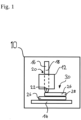
- FIG. 1 schematically shows an exemplary embodiment of an additive manufacturing machine 10.
- the additive manufacturing machine 10 has a tool head 12 which is disposed so as to be able to move relative to a printing bed 14.
- the relative movement between the tool head 12 and the printing bed 14 herein can result from a movement of the tool head as well as from a movement of the printing bed.
- the tool head 12 by means of a conveying device 24, is configured for conveying a semi-finished product 16 which is composed of a manufacturing material and has a semi-finished product longitudinal axis, for example a profile bar 18 having a profile bar longitudinal axis, from an input portion 20 to an output portion 22.
- the input portion 20 is configured for receiving the profile bar 18 and for feeding the latter to the conveying device 24.
- the conveying device 24, by virtue of control commands, conveys the profile bar 18 to the output portion 22 where the profile bar 18 by means of a heating installation 23 is heated so as to melt, and thereafter is deposited on the printing bed 14 or on an already existing component layer 26 by an exit nozzle 25, so as to thereafter form a further component layer 28 and successively form the desired component 30.
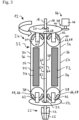
- Fig. 2 illustrates in more detail the tool head 12, or the conveying device 24, respectively.
- the conveying device 24 has a longitudinal conveying mechanism 32.
- the longitudinal conveying mechanism 32 is configured for conveying the profile bar 18 along a conveying direction F from the input portion 20 to the output portion 22.
- the longitudinal conveying mechanism 32 for conveying the profile bar 18 comprises at least one conveying means 34 which extends so as to be parallel to the conveying direction F.
- the conveying means 34 is configured as a conveying belt or a conveyor belt 36, for example.
- the conveying means 34 is in particular provided as a continuously revolving conveying means 34.
- the longitudinal conveying mechanism 32 comprises at least one drive roller 38 which engages the conveying means 34 so as to drive the latter. Besides the at least one drive roller 38, the longitudinal conveying mechanism 32 comprises at least one deflection roller 40 which deflects the conveying means 34 back onto the drive roller 38.
- the deflection roller 40 can moreover be configured as a drive roller 38.
- the drive roller 38 and the deflection roller 40 are provided on the longitudinal conveying mechanism 32 so as to be mutually spaced apart in the conveying direction F.
- the longitudinal conveying mechanism 32 can moreover have a tensioning device 42 which keeps the conveying means 34 under tension.
- the tensioning device 42 on account of an adjustable spacing of the drive roller 38 from the deflection roller 40, can tension the conveying means 34, on the one hand.
- the tensioning device 42 can have at least one tension roller which effects the tensioning of the conveying means 34 on the side that faces away from the profile bar 18.
- the conveying device 24 can furthermore comprise a rotating mechanism 44.
- the rotating mechanism 44 is configured for rotating the profile bar 18 about the profile bar longitudinal axis of the latter in that the force is transmitted to the profile bar 18 by way of the conveying means 34.
- the rotating mechanism 44 has a rotary drive actuator 46, for example a motor.
- the driving power of the rotary drive actuator 46 is transmitted to a turntable 50 by means of a rotary drive gearbox 48.
- the longitudinal conveying mechanism 32 is preferably supported on the turntable 50.
- the drive roller 38 and/or the deflection roller 40 are/is in particular disposed on the turntable 50.
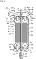
- the rotating mechanism 44 can furthermore have a further turntable 52 which in the conveying direction F is spaced apart from the turntable 50 and on which a drive roller 38 and/or a deflection roller 40 are/is likewise disposed.
- the input portion 20 is furthermore provided on the turntable 50, while the output portion 22 can be disposed on the further turntable 52.
- the longitudinal conveying mechanism 32 preferably comprises a first conveying means 54 and a second conveying means 56.
- the first conveying means 54 comprises a first conveying portion 58
- the second conveying means 56 comprises a second conveying portion 60.
- the first conveying portion 58 and the second conveying portion 60 are disposed so as to face one another and conjointly define a conveying duct 62 in which the profile bar 18 can be received for conveying.
- Each conveying portion 58, 60 is preferably provided on a load strand 64 of the conveying means 34.
- the profile bar 18 is inserted into the input portion 20.
- the profile bar 18 thereafter is preferably engaged by a pair of conveying rollers 66, such as, for example, the drive roller 36 and/or the deflection roller 40, and introduced into the conveying duct 62.
- the conveying means 34 can hug the circumferential face of the profile bar and thus engage a large part of the circumferential face of the profile bar.
- the conveying means 34 conveys the profile bar in the direction toward the output portion 22.
- the profile bar 18 passes a second pair of conveying rollers 66, for example a drive roller 38 and/or a deflection roller 40, and thereafter enters the output portion 22 through the further turntable 52.
- the profile bar 18 is melted by the heating installation 23 and by means of the exit nozzle 25 ejected in the direction toward the printing bed 14.
- each conveying portion 58, 60 is engaged by each conveying portion 58, 60 along the entire conveying duct 62.
- Each conveying portion 58, 60 accordingly extends from the conveying roller 66 on the turntable 50 up to the conveying roller 66 on the further turntable 52.
- the torque can be transmitted to the profile bar 18 by activating the rotating mechanism 44 such that said profile bar 18 can be rotated about the profile bar longitudinal axis of the latter.
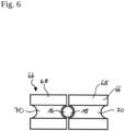
- Fig. 6 shows a cross section along the line VI-VI from Fig. 2 .
- the conveying rollers 66 are configured as profiled rollers 68.
- Each profiled roller 68 comprises a profile groove 70 which is adapted to the cross-sectional shape of the profile bar 18.
- the profile bar 18 in the present example has a circular cross section so that the profile groove 70 has a semicircular shape.
- other cross-sectional shapes of the profile bar for example elliptic, rectangular, or square, are also conceivable.
- the profile groove 70 in this instance has the correspondingly complementary shape which is adapted to the cross section of the profile bar 18.
- the conveying device 24 comprises a contact pressure device 72 which is configured for pushing the conveying means 34 against the profile bar 18.
- the contact pressure device 72 can have a fluid chamber 74 which is able to be deformed by a fluid pressure.
- the fluid chamber 74 in a non-supplied state ( Fig. 3 ) is released from the conveying means such that a configuration as in the tool head 12 from Fig. 2 results.
- the fluid chamber 74 can be supplied with a fluid pressure ( Fig. 4 ) such that the fluid chamber 74 urges the conveying means 34 against the profile bar.
- the fluid chamber 74 is preferably configured as a deformable fluid cushion 75.
- the contact pressure device 72 can have a plurality of contact pressure rollers 76 which by virtue of an elastic element 78, for example a spring 80, urge the conveying means 34 in the direction toward the profile bar 18, as is illustrated in more detail in Fig. 5 .
- an elastic element 78 for example a spring 80
- a conveying device by way of which the 3D printing rate can be increased and the reliability of transporting a semi-finished product to be processed in an additive manufacturing machine can be improved is specified by the measures described above.
- the conveying device comprises a longitudinal conveying mechanism which conveys the semi-finished product along a conveying direction in that a preferably continuously revolving conveying means, for example a conveyor belt or a conveying belt, engages the semi-finished product in a force-fitting and/or form-fitting manner.
Landscapes
- Chemical & Material Sciences (AREA)
- Engineering & Computer Science (AREA)
- Materials Engineering (AREA)
- Manufacturing & Machinery (AREA)
- Physics & Mathematics (AREA)
- Mechanical Engineering (AREA)
- Optics & Photonics (AREA)
Claims (14)
- Fördereinrichtung (24) für eine additive Fertigungsmaschine (10), wobei die Fördereinrichtung (24) zum Fördern eines Halbzeugs (16) ausgebildet ist, das aus einem von der additiven Fertigungsmaschine (10) zu bearbeitenden Fertigungsmaterial besteht und eine Halbzeug-Längsachse aufweist, wobei die Fördereinrichtung (24) einen Längsfördermechanismus (32) umfasst, der zum Fördern des Halbzeugs (16) entlang einer Förderrichtung parallel zur Halbzeug-Längsachse ausgebildet ist, wobei der Längsfördermechanismus (32) mindestens ein laufendes Fördermittel (34, 54, 56) aufweist, das sich entlang der Förderrichtung erstreckt und das einen Förderabschnitt (58, 60) aufweist, der dazu ausgebildet ist, einen Halbzeugabschnitt des Halbzeugs (16) derart in Eingriff zu nehmen, dass das Halbzeug (16) in der Förderrichtung bewegbar ist, wobei die Längsfördereinrichtung (32) eine Andruckeinrichtung (72) aufweist, die dazu ausgebildet ist, das Fördermittel (34, 54, 56) gegen das Halbzeug (16) zu drücken, um das Halbzeug (16) zu bewegen, dadurch gekennzeichnet, dass die Andruckeinrichtung (72) eine Fluidkammer (74) aufweist, die mit einem Fluiddruck beaufschlagbar ist, wobei die Fluidkammer (74), die durch den Fluiddruck verformbar ist und die in einem beaufschlagten Zustand dazu ausgebildet ist, das Fördermittel (34, 54, 56) in die Richtung hin zu dem Halbzeug (16) zu drücken, um das Halbzeug (16) zu bewegen, und insbesondere in einem nicht beaufschlagten Zustand keine Kraft auf das Fördermittel (34, 54, 56) auszuüben, die ausreicht, um das Halbzeug (16) zu bewegen.
- Fördereinrichtung (24) nach Anspruch 1, wobei das laufende Fördermittel (34, 54, 56) ein Fördergurt oder ein Förderband (36) ist.
- Fördereinrichtung (24) nach einem der vorhergehenden Ansprüche, wobei der Förderabschnitt (58, 60) an einem Lasttrum (64) des laufenden Fördermittels (34, 54, 56) angeordnet ist.
- Fördereinrichtung (24) nach einem der vorhergehenden Ansprüche, wobei der Längsfördermechanismus (32) eine Umlenkrolle (40) aufweist, die das Fördermittel (34, 54, 56) umlenkt.
- Fördereinrichtung (24) nach einem der vorhergehenden Ansprüche, wobei der Längsfördermechanismus (32) eine Antriebsrolle (38) aufweist, die das Fördermittel (34, 54, 56) in Eingriff nimmt, um das Fördermittel (34, 54, 56) anzutreiben.
- Fördereinrichtung (24) nach einem der vorhergehenden Ansprüche, wobei der Längsfördermechanismus (32) eine Spanneinrichtung (42) aufweist, die das Fördermittel (34, 54, 56) unter Spannung hält.
- Fördereinrichtung (24) nach einem der vorhergehenden Ansprüche, wobei das Fördermittel (34, 54, 56) derart ausgebildet ist, dass das Fördermittel (34, 54, 56) bei Drücken auf das Halbzeug (16) an dem Halbzeug (16) haftet und die Umfangsfläche des Halbzeugs jedenfalls teilweise umschließt, insbesondere diese jedenfalls zu einem Fünftel, genauer gesagt jedenfalls zu einem Drittel in Eingriff nimmt.
- Fördereinrichtung (24) nach einem der Ansprüche 4 bis 7, wobei die Umlenkrolle (40) und/oder die Antriebsrolle (38) und/oder die Andruckrolle (76) ein profiliertes Merkmal aufweisen/aufweist, das der Kontur des Halbzeugs entspricht.
- Fördereinrichtung (24) nach einem der vorhergehenden Ansprüche, umfassend ein erstes laufendes Fördermittel (54) und ein zweites laufendes Fördermittel (56), die gemeinsam einen Förderkanal (62) definieren, durch den das Halbzeug (16) aufgrund der Bewegung der Fördermittel (34, 54, 56) in der Förderrichtung förderbar ist.
- Fördereinrichtung (24) nach einem der vorhergehenden Ansprüche, umfassend einen Drehmechanismus (44), der zum Antreiben des Längsfördermechanismus (32) derart ausgebildet ist, dass das Halbzeug (16) um die Halbzeug-Längsachse davon drehbar ist.
- Fördereinrichtung (24) nach Anspruch 10, wobei der Drehmechanismus (44) mindestens einen Drehtisch (50) aufweist, der antreibbar ist und auf dem der Längsfördermechanismus (32) derart gestützt ist, dass der Längsfördermechanismus (32) bei Antreiben des Drehtischs (50) eine Drehbewegung ausführt.
- Fördereinrichtung (24) nach Anspruch 10 oder 11, wobei der Drehmechanismus (44), insbesondere der Drehtisch (50), eine Einlauföffnung für das Halbzeug (16) aufweist, um das Halbzeug (16) dem Fördermittel (34, 54, 56) zuzuführen.
- Werkzeugkopf (12) zur Montage und Verwendung in einer additiven Fertigungsmaschine (10), wobei der Werkzeugkopf (12) einen Eingangsabschnitt (20) für ein Halbzeug (16), das aus einem von der additiven Fertigungsmaschine (10) zu verarbeitenden Fertigungsmaterial besteht und eine Halbzeug-Längsachse aufweist, einen Ausgangsabschnitt (22), der dazu ausgebildet ist, geschmolzenes Fertigungsmaterial auf einem Druckbett abzulagern, um ein Bauteil (30) zu fertigen, sowie eine Fördereinrichtung (24) nach einem der vorhergehenden Ansprüche umfasst, die dazu ausgebildet ist, das Halbzeug (16) von dem Eingangsabschnitt (20) zu dem Ausgangsabschnitt (22) zu fördern und das Halbzeug (16) auf dem Werkzeugkopf (12) zu halten.
- Additive Fertigungsmaschine (10), die dazu ausgebildet ist, ein Schmelzschichtungsverfahren zum Fertigen eines Bauteils (30), insbesondere für ein Luftfahrzeug, durchzuführen, wobei die Fertigungsmaschine dazu ausgebildet ist, Fertigungsmaterial zu bearbeiten, das so konfektioniert ist, dass es Profilstäbe (18) bildet, wobei die Fertigungsmaschine eine Fördereinrichtung (24) nach einem der Ansprüche 1 bis 12 zum Fördern des Halbzeugs (16) und/oder einen Werkzeugkopf (12) nach Anspruch 13 zum Bearbeiten des Halbzeugs (16) umfasst.
Applications Claiming Priority (1)
| Application Number | Priority Date | Filing Date | Title |
|---|---|---|---|
| DE102019116694.2A DE102019116694A1 (de) | 2019-06-19 | 2019-06-19 | Fördereinrichtung und Arbeitskopf für eine additive Fertigungsmaschine sowie additive Fertigungsmaschine |
Publications (2)
| Publication Number | Publication Date |
|---|---|
| EP3753708A1 EP3753708A1 (de) | 2020-12-23 |
| EP3753708B1 true EP3753708B1 (de) | 2025-01-15 |
Family
ID=71108504
Family Applications (1)
| Application Number | Title | Priority Date | Filing Date |
|---|---|---|---|
| EP20180834.2A Active EP3753708B1 (de) | 2019-06-19 | 2020-06-18 | Fördervorrichtung und werkzeugkopf für eine maschine zur generativen fertigung und maschine zur generativen fertigung |
Country Status (4)
| Country | Link |
|---|---|
| US (1) | US12128617B2 (de) |
| EP (1) | EP3753708B1 (de) |
| DE (1) | DE102019116694A1 (de) |
| ES (1) | ES3015461T3 (de) |
Families Citing this family (5)
| Publication number | Priority date | Publication date | Assignee | Title |
|---|---|---|---|---|
| DE102019116694A1 (de) | 2019-06-19 | 2020-12-24 | Airbus Operations Gmbh | Fördereinrichtung und Arbeitskopf für eine additive Fertigungsmaschine sowie additive Fertigungsmaschine |
| EP4046778A1 (de) * | 2021-02-18 | 2022-08-24 | InnovatiQ GmbH + Co KG | Vorrichtung und verfahren zum transport von filamenten und vorrichtung zum drucken von dreidimensionalen objekten |
| CN113021894A (zh) * | 2021-03-11 | 2021-06-25 | 南通理工学院 | 一种3d打印机柔性进料机构 |
| CN116690970A (zh) * | 2023-05-20 | 2023-09-05 | 南京航空航天大学 | 大丝束连续纤维复材新型3d打印双头协同打印装置 |
| CN117428968A (zh) * | 2023-12-12 | 2024-01-23 | 一汽解放汽车有限公司 | 塑料耗材回收装置以及3d打印机 |
Citations (2)
| Publication number | Priority date | Publication date | Assignee | Title |
|---|---|---|---|---|
| WO2015073322A1 (en) * | 2013-11-13 | 2015-05-21 | Abb Technology Ag | System for robotic 3d printing |
| WO2016083181A1 (en) * | 2014-11-27 | 2016-06-02 | Philips Lighting Holding B.V. | Printing head, printing apparatus, printing method and printed article |
Family Cites Families (10)
| Publication number | Priority date | Publication date | Assignee | Title |
|---|---|---|---|---|
| US5121329A (en) * | 1989-10-30 | 1992-06-09 | Stratasys, Inc. | Apparatus and method for creating three-dimensional objects |
| US5764521A (en) | 1995-11-13 | 1998-06-09 | Stratasys Inc. | Method and apparatus for solid prototyping |
| US5738817A (en) | 1996-02-08 | 1998-04-14 | Rutgers, The State University | Solid freeform fabrication methods |
| US7384255B2 (en) * | 2005-07-01 | 2008-06-10 | Stratasys, Inc. | Rapid prototyping system with controlled material feedstock |
| US8157200B2 (en) * | 2009-07-24 | 2012-04-17 | The Procter & Gamble Company | Process for winding a web material |
| CN104097327B (zh) | 2014-07-11 | 2017-01-25 | 东莞中国科学院云计算产业技术创新与育成中心 | 3d打印机喷丝截面积可调结构及其速度和精度控制方法 |
| DE102015122647A1 (de) * | 2015-12-22 | 2017-06-22 | Arburg Gmbh + Co. Kg | Vorrichtung und Verfahren zur Herstellung eines dreidimensionalen Gegenstandes mit einer Faserzuführeinrichtung |
| TWI602765B (zh) * | 2016-12-02 | 2017-10-21 | 財團法人工業技術研究院 | 三維列印供料裝置與可變孔口裝置 |
| JP7005426B2 (ja) * | 2017-11-09 | 2022-01-21 | エス.ラボ株式会社 | 造形装置及び造形物の製造方法 |
| DE102019116694A1 (de) | 2019-06-19 | 2020-12-24 | Airbus Operations Gmbh | Fördereinrichtung und Arbeitskopf für eine additive Fertigungsmaschine sowie additive Fertigungsmaschine |
-
2019
- 2019-06-19 DE DE102019116694.2A patent/DE102019116694A1/de not_active Withdrawn
-
2020
- 2020-06-17 US US16/903,494 patent/US12128617B2/en active Active
- 2020-06-18 EP EP20180834.2A patent/EP3753708B1/de active Active
- 2020-06-18 ES ES20180834T patent/ES3015461T3/es active Active
Patent Citations (2)
| Publication number | Priority date | Publication date | Assignee | Title |
|---|---|---|---|---|
| WO2015073322A1 (en) * | 2013-11-13 | 2015-05-21 | Abb Technology Ag | System for robotic 3d printing |
| WO2016083181A1 (en) * | 2014-11-27 | 2016-06-02 | Philips Lighting Holding B.V. | Printing head, printing apparatus, printing method and printed article |
Also Published As
| Publication number | Publication date |
|---|---|
| ES3015461T3 (en) | 2025-05-05 |
| EP3753708A1 (de) | 2020-12-23 |
| US20200398487A1 (en) | 2020-12-24 |
| US12128617B2 (en) | 2024-10-29 |
| DE102019116694A1 (de) | 2020-12-24 |
Similar Documents
| Publication | Publication Date | Title |
|---|---|---|
| EP3753708B1 (de) | Fördervorrichtung und werkzeugkopf für eine maschine zur generativen fertigung und maschine zur generativen fertigung | |
| EP3611007B1 (de) | Druckkopf für die generative fertigung von artikeln | |
| CA2680442C (en) | Elastic fibre laying die, laying device comprising such a die, and use of said device | |
| CN105579220B (zh) | 用于纤维增强的添加制造的装置 | |
| US11548213B2 (en) | Additive manufacturing device, additive manufacturing method, and profile rod therefor | |
| US8438825B2 (en) | Head for the application of reinforcing threads on a deposition surface | |
| CN111867808A (zh) | 纤维增强3d打印 | |
| US20240001634A1 (en) | Method and device for cutting off an extrudate | |
| CN112606432B (zh) | 一种用于复合材料预浸带成型制造的铺带装置 | |
| JPH04341830A (ja) | デリバリーヘッド | |
| CA2680457A1 (en) | Spreading device for spreading out fibre filament bundles, and spreading method carried out using same | |
| US20200290271A1 (en) | Filament deposition head and method of depositing filament material for joining workpieces | |
| EP2366042B1 (de) | Hackgerät für verwirbelte fasern | |
| CN111448067A (zh) | 用于机床的3d打印工具 | |
| CN112248432A (zh) | 一种熔融式三维打印机送料装置 | |
| US11667077B2 (en) | Conveying installation and tool head for an additive manufacturing machine, and additive manufacturing machine | |
| KR102082632B1 (ko) | 보강 섬유 다발들의 제어된 침착을 위한 침착 디바이스 | |
| US20250296282A1 (en) | Extrusion device and 3d printer | |
| CN113442429A (zh) | 造型材料连接装置以及造型装置 | |
| EP3071503B1 (de) | Oberflächenumformung des riemens für ein aufzugssystem | |
| US20240351279A1 (en) | Print head design for additive manufacturing using continuous fibers and thermoplastic matrix materials for cutting in the hot zone of the print head by an axial or rotational movement | |
| JP3497137B2 (ja) | 供給アーム | |
| KR20220012237A (ko) | 복합 구조체를 적층 제조하기 위한 시스템 |
Legal Events
| Date | Code | Title | Description |
|---|---|---|---|
| PUAI | Public reference made under article 153(3) epc to a published international application that has entered the european phase |
Free format text: ORIGINAL CODE: 0009012 |
|
| STAA | Information on the status of an ep patent application or granted ep patent |
Free format text: STATUS: THE APPLICATION HAS BEEN PUBLISHED |
|
| AK | Designated contracting states |
Kind code of ref document: A1 Designated state(s): AL AT BE BG CH CY CZ DE DK EE ES FI FR GB GR HR HU IE IS IT LI LT LU LV MC MK MT NL NO PL PT RO RS SE SI SK SM TR |
|
| AX | Request for extension of the european patent |
Extension state: BA ME |
|
| STAA | Information on the status of an ep patent application or granted ep patent |
Free format text: STATUS: REQUEST FOR EXAMINATION WAS MADE |
|
| 17P | Request for examination filed |
Effective date: 20210622 |
|
| RBV | Designated contracting states (corrected) |
Designated state(s): AL AT BE BG CH CY CZ DE DK EE ES FI FR GB GR HR HU IE IS IT LI LT LU LV MC MK MT NL NO PL PT RO RS SE SI SK SM TR |
|
| STAA | Information on the status of an ep patent application or granted ep patent |
Free format text: STATUS: EXAMINATION IS IN PROGRESS |
|
| 17Q | First examination report despatched |
Effective date: 20230403 |
|
| GRAP | Despatch of communication of intention to grant a patent |
Free format text: ORIGINAL CODE: EPIDOSNIGR1 |
|
| STAA | Information on the status of an ep patent application or granted ep patent |
Free format text: STATUS: GRANT OF PATENT IS INTENDED |
|
| INTG | Intention to grant announced |
Effective date: 20240823 |
|
| GRAS | Grant fee paid |
Free format text: ORIGINAL CODE: EPIDOSNIGR3 |
|
| GRAA | (expected) grant |
Free format text: ORIGINAL CODE: 0009210 |
|
| STAA | Information on the status of an ep patent application or granted ep patent |
Free format text: STATUS: THE PATENT HAS BEEN GRANTED |
|
| AK | Designated contracting states |
Kind code of ref document: B1 Designated state(s): AL AT BE BG CH CY CZ DE DK EE ES FI FR GB GR HR HU IE IS IT LI LT LU LV MC MK MT NL NO PL PT RO RS SE SI SK SM TR |
|
| REG | Reference to a national code |
Ref country code: CH Ref legal event code: EP Ref country code: GB Ref legal event code: FG4D |
|
| REG | Reference to a national code |
Ref country code: DE Ref legal event code: R096 Ref document number: 602020044714 Country of ref document: DE |
|
| REG | Reference to a national code |
Ref country code: IE Ref legal event code: FG4D |
|
| REG | Reference to a national code |
Ref country code: NL Ref legal event code: MP Effective date: 20250115 |
|
| PG25 | Lapsed in a contracting state [announced via postgrant information from national office to epo] |
Ref country code: NL Free format text: LAPSE BECAUSE OF FAILURE TO SUBMIT A TRANSLATION OF THE DESCRIPTION OR TO PAY THE FEE WITHIN THE PRESCRIBED TIME-LIMIT Effective date: 20250115 |
|
| PG25 | Lapsed in a contracting state [announced via postgrant information from national office to epo] |
Ref country code: RS Free format text: LAPSE BECAUSE OF FAILURE TO SUBMIT A TRANSLATION OF THE DESCRIPTION OR TO PAY THE FEE WITHIN THE PRESCRIBED TIME-LIMIT Effective date: 20250415 |
|
| PG25 | Lapsed in a contracting state [announced via postgrant information from national office to epo] |
Ref country code: FI Free format text: LAPSE BECAUSE OF FAILURE TO SUBMIT A TRANSLATION OF THE DESCRIPTION OR TO PAY THE FEE WITHIN THE PRESCRIBED TIME-LIMIT Effective date: 20250115 |
|
| PG25 | Lapsed in a contracting state [announced via postgrant information from national office to epo] |
Ref country code: PL Free format text: LAPSE BECAUSE OF FAILURE TO SUBMIT A TRANSLATION OF THE DESCRIPTION OR TO PAY THE FEE WITHIN THE PRESCRIBED TIME-LIMIT Effective date: 20250115 |
|
| PGFP | Annual fee paid to national office [announced via postgrant information from national office to epo] |
Ref country code: DE Payment date: 20250618 Year of fee payment: 6 |
|
| PGFP | Annual fee paid to national office [announced via postgrant information from national office to epo] |
Ref country code: GB Payment date: 20250618 Year of fee payment: 6 |
|
| REG | Reference to a national code |
Ref country code: LT Ref legal event code: MG9D |
|
| PG25 | Lapsed in a contracting state [announced via postgrant information from national office to epo] |
Ref country code: IS Free format text: LAPSE BECAUSE OF FAILURE TO SUBMIT A TRANSLATION OF THE DESCRIPTION OR TO PAY THE FEE WITHIN THE PRESCRIBED TIME-LIMIT Effective date: 20250515 Ref country code: NO Free format text: LAPSE BECAUSE OF FAILURE TO SUBMIT A TRANSLATION OF THE DESCRIPTION OR TO PAY THE FEE WITHIN THE PRESCRIBED TIME-LIMIT Effective date: 20250415 |
|
| REG | Reference to a national code |
Ref country code: AT Ref legal event code: MK05 Ref document number: 1759591 Country of ref document: AT Kind code of ref document: T Effective date: 20250115 |
|
| PG25 | Lapsed in a contracting state [announced via postgrant information from national office to epo] |
Ref country code: HR Free format text: LAPSE BECAUSE OF FAILURE TO SUBMIT A TRANSLATION OF THE DESCRIPTION OR TO PAY THE FEE WITHIN THE PRESCRIBED TIME-LIMIT Effective date: 20250115 |
|
| PG25 | Lapsed in a contracting state [announced via postgrant information from national office to epo] |
Ref country code: LV Free format text: LAPSE BECAUSE OF FAILURE TO SUBMIT A TRANSLATION OF THE DESCRIPTION OR TO PAY THE FEE WITHIN THE PRESCRIBED TIME-LIMIT Effective date: 20250115 Ref country code: PT Free format text: LAPSE BECAUSE OF FAILURE TO SUBMIT A TRANSLATION OF THE DESCRIPTION OR TO PAY THE FEE WITHIN THE PRESCRIBED TIME-LIMIT Effective date: 20250515 |
|
| PGFP | Annual fee paid to national office [announced via postgrant information from national office to epo] |
Ref country code: FR Payment date: 20250626 Year of fee payment: 6 |
|
| PG25 | Lapsed in a contracting state [announced via postgrant information from national office to epo] |
Ref country code: BG Free format text: LAPSE BECAUSE OF FAILURE TO SUBMIT A TRANSLATION OF THE DESCRIPTION OR TO PAY THE FEE WITHIN THE PRESCRIBED TIME-LIMIT Effective date: 20250115 Ref country code: GR Free format text: LAPSE BECAUSE OF FAILURE TO SUBMIT A TRANSLATION OF THE DESCRIPTION OR TO PAY THE FEE WITHIN THE PRESCRIBED TIME-LIMIT Effective date: 20250416 |
|
| PG25 | Lapsed in a contracting state [announced via postgrant information from national office to epo] |
Ref country code: AT Free format text: LAPSE BECAUSE OF FAILURE TO SUBMIT A TRANSLATION OF THE DESCRIPTION OR TO PAY THE FEE WITHIN THE PRESCRIBED TIME-LIMIT Effective date: 20250115 |
|
| PG25 | Lapsed in a contracting state [announced via postgrant information from national office to epo] |
Ref country code: SE Free format text: LAPSE BECAUSE OF FAILURE TO SUBMIT A TRANSLATION OF THE DESCRIPTION OR TO PAY THE FEE WITHIN THE PRESCRIBED TIME-LIMIT Effective date: 20250115 |
|
| PG25 | Lapsed in a contracting state [announced via postgrant information from national office to epo] |
Ref country code: SM Free format text: LAPSE BECAUSE OF FAILURE TO SUBMIT A TRANSLATION OF THE DESCRIPTION OR TO PAY THE FEE WITHIN THE PRESCRIBED TIME-LIMIT Effective date: 20250115 |
|
| PGFP | Annual fee paid to national office [announced via postgrant information from national office to epo] |
Ref country code: ES Payment date: 20250731 Year of fee payment: 6 |
|
| PG25 | Lapsed in a contracting state [announced via postgrant information from national office to epo] |
Ref country code: DK Free format text: LAPSE BECAUSE OF FAILURE TO SUBMIT A TRANSLATION OF THE DESCRIPTION OR TO PAY THE FEE WITHIN THE PRESCRIBED TIME-LIMIT Effective date: 20250115 |
|
| PGFP | Annual fee paid to national office [announced via postgrant information from national office to epo] |
Ref country code: IT Payment date: 20250624 Year of fee payment: 6 |
|
| REG | Reference to a national code |
Ref country code: DE Ref legal event code: R097 Ref document number: 602020044714 Country of ref document: DE |
|
| PG25 | Lapsed in a contracting state [announced via postgrant information from national office to epo] |
Ref country code: CZ Free format text: LAPSE BECAUSE OF FAILURE TO SUBMIT A TRANSLATION OF THE DESCRIPTION OR TO PAY THE FEE WITHIN THE PRESCRIBED TIME-LIMIT Effective date: 20250115 Ref country code: EE Free format text: LAPSE BECAUSE OF FAILURE TO SUBMIT A TRANSLATION OF THE DESCRIPTION OR TO PAY THE FEE WITHIN THE PRESCRIBED TIME-LIMIT Effective date: 20250115 |
|
| PG25 | Lapsed in a contracting state [announced via postgrant information from national office to epo] |
Ref country code: RO Free format text: LAPSE BECAUSE OF FAILURE TO SUBMIT A TRANSLATION OF THE DESCRIPTION OR TO PAY THE FEE WITHIN THE PRESCRIBED TIME-LIMIT Effective date: 20250115 |
|
| PG25 | Lapsed in a contracting state [announced via postgrant information from national office to epo] |
Ref country code: SK Free format text: LAPSE BECAUSE OF FAILURE TO SUBMIT A TRANSLATION OF THE DESCRIPTION OR TO PAY THE FEE WITHIN THE PRESCRIBED TIME-LIMIT Effective date: 20250115 |
|
| PLBE | No opposition filed within time limit |
Free format text: ORIGINAL CODE: 0009261 |
|
| STAA | Information on the status of an ep patent application or granted ep patent |
Free format text: STATUS: NO OPPOSITION FILED WITHIN TIME LIMIT |
|
| REG | Reference to a national code |
Ref country code: CH Ref legal event code: L10 Free format text: ST27 STATUS EVENT CODE: U-0-0-L10-L00 (AS PROVIDED BY THE NATIONAL OFFICE) Effective date: 20251126 |
|
| 26N | No opposition filed |
Effective date: 20251016 |
|
| REG | Reference to a national code |
Ref country code: CH Ref legal event code: H13 Free format text: ST27 STATUS EVENT CODE: U-0-0-H10-H13 (AS PROVIDED BY THE NATIONAL OFFICE) Effective date: 20260127 |
|
| PG25 | Lapsed in a contracting state [announced via postgrant information from national office to epo] |
Ref country code: MC Free format text: LAPSE BECAUSE OF FAILURE TO SUBMIT A TRANSLATION OF THE DESCRIPTION OR TO PAY THE FEE WITHIN THE PRESCRIBED TIME-LIMIT Effective date: 20250115 |
|
| PG25 | Lapsed in a contracting state [announced via postgrant information from national office to epo] |
Ref country code: LU Free format text: LAPSE BECAUSE OF NON-PAYMENT OF DUE FEES Effective date: 20250618 |
|
| REG | Reference to a national code |
Ref country code: BE Ref legal event code: MM Effective date: 20250630 |
|
| PG25 | Lapsed in a contracting state [announced via postgrant information from national office to epo] |
Ref country code: IE Free format text: LAPSE BECAUSE OF NON-PAYMENT OF DUE FEES Effective date: 20250618 |
|
| PG25 | Lapsed in a contracting state [announced via postgrant information from national office to epo] |
Ref country code: BE Free format text: LAPSE BECAUSE OF NON-PAYMENT OF DUE FEES Effective date: 20250630 |