EP3753472A1 - Video endoscope and handle for a video endoscope including rotational support means - Google Patents
Video endoscope and handle for a video endoscope including rotational support means Download PDFInfo
- Publication number
- EP3753472A1 EP3753472A1 EP20181308.6A EP20181308A EP3753472A1 EP 3753472 A1 EP3753472 A1 EP 3753472A1 EP 20181308 A EP20181308 A EP 20181308A EP 3753472 A1 EP3753472 A1 EP 3753472A1
- Authority
- EP
- European Patent Office
- Prior art keywords
- handle
- interface portion
- shaft
- bearing
- video endoscope
- Prior art date
- Legal status (The legal status is an assumption and is not a legal conclusion. Google has not performed a legal analysis and makes no representation as to the accuracy of the status listed.)
- Pending
Links
Images



Classifications
-
- A—HUMAN NECESSITIES
- A61—MEDICAL OR VETERINARY SCIENCE; HYGIENE
- A61B—DIAGNOSIS; SURGERY; IDENTIFICATION
- A61B1/00—Instruments for performing medical examinations of the interior of cavities or tubes of the body by visual or photographical inspection, e.g. endoscopes; Illuminating arrangements therefor
- A61B1/00064—Constructional details of the endoscope body
- A61B1/00066—Proximal part of endoscope body, e.g. handles
-
- A—HUMAN NECESSITIES
- A61—MEDICAL OR VETERINARY SCIENCE; HYGIENE
- A61B—DIAGNOSIS; SURGERY; IDENTIFICATION
- A61B1/00—Instruments for performing medical examinations of the interior of cavities or tubes of the body by visual or photographical inspection, e.g. endoscopes; Illuminating arrangements therefor
- A61B1/00002—Operational features of endoscopes
- A61B1/00004—Operational features of endoscopes characterised by electronic signal processing
- A61B1/00009—Operational features of endoscopes characterised by electronic signal processing of image signals during a use of endoscope
-
- A—HUMAN NECESSITIES
- A61—MEDICAL OR VETERINARY SCIENCE; HYGIENE
- A61B—DIAGNOSIS; SURGERY; IDENTIFICATION
- A61B1/00—Instruments for performing medical examinations of the interior of cavities or tubes of the body by visual or photographical inspection, e.g. endoscopes; Illuminating arrangements therefor
- A61B1/00002—Operational features of endoscopes
- A61B1/00011—Operational features of endoscopes characterised by signal transmission
- A61B1/00018—Operational features of endoscopes characterised by signal transmission using electrical cables
-
- A—HUMAN NECESSITIES
- A61—MEDICAL OR VETERINARY SCIENCE; HYGIENE
- A61B—DIAGNOSIS; SURGERY; IDENTIFICATION
- A61B1/00—Instruments for performing medical examinations of the interior of cavities or tubes of the body by visual or photographical inspection, e.g. endoscopes; Illuminating arrangements therefor
- A61B1/00002—Operational features of endoscopes
- A61B1/00025—Operational features of endoscopes characterised by power management
- A61B1/00027—Operational features of endoscopes characterised by power management characterised by power supply
-
- A—HUMAN NECESSITIES
- A61—MEDICAL OR VETERINARY SCIENCE; HYGIENE
- A61B—DIAGNOSIS; SURGERY; IDENTIFICATION
- A61B1/00—Instruments for performing medical examinations of the interior of cavities or tubes of the body by visual or photographical inspection, e.g. endoscopes; Illuminating arrangements therefor
- A61B1/00002—Operational features of endoscopes
- A61B1/00039—Operational features of endoscopes provided with input arrangements for the user
- A61B1/00042—Operational features of endoscopes provided with input arrangements for the user for mechanical operation
-
- A—HUMAN NECESSITIES
- A61—MEDICAL OR VETERINARY SCIENCE; HYGIENE
- A61B—DIAGNOSIS; SURGERY; IDENTIFICATION
- A61B1/00—Instruments for performing medical examinations of the interior of cavities or tubes of the body by visual or photographical inspection, e.g. endoscopes; Illuminating arrangements therefor
- A61B1/00064—Constructional details of the endoscope body
- A61B1/00071—Insertion part of the endoscope body
- A61B1/00073—Insertion part of the endoscope body with externally grooved shaft
-
- A—HUMAN NECESSITIES
- A61—MEDICAL OR VETERINARY SCIENCE; HYGIENE
- A61B—DIAGNOSIS; SURGERY; IDENTIFICATION
- A61B1/00—Instruments for performing medical examinations of the interior of cavities or tubes of the body by visual or photographical inspection, e.g. endoscopes; Illuminating arrangements therefor
- A61B1/00064—Constructional details of the endoscope body
- A61B1/00105—Constructional details of the endoscope body characterised by modular construction
-
- A—HUMAN NECESSITIES
- A61—MEDICAL OR VETERINARY SCIENCE; HYGIENE
- A61B—DIAGNOSIS; SURGERY; IDENTIFICATION
- A61B1/00—Instruments for performing medical examinations of the interior of cavities or tubes of the body by visual or photographical inspection, e.g. endoscopes; Illuminating arrangements therefor
- A61B1/00112—Connection or coupling means
- A61B1/00121—Connectors, fasteners and adapters, e.g. on the endoscope handle
- A61B1/00124—Connectors, fasteners and adapters, e.g. on the endoscope handle electrical, e.g. electrical plug-and-socket connection
-
- A—HUMAN NECESSITIES
- A61—MEDICAL OR VETERINARY SCIENCE; HYGIENE
- A61B—DIAGNOSIS; SURGERY; IDENTIFICATION
- A61B1/00—Instruments for performing medical examinations of the interior of cavities or tubes of the body by visual or photographical inspection, e.g. endoscopes; Illuminating arrangements therefor
- A61B1/00112—Connection or coupling means
- A61B1/00121—Connectors, fasteners and adapters, e.g. on the endoscope handle
- A61B1/00128—Connectors, fasteners and adapters, e.g. on the endoscope handle mechanical, e.g. for tubes or pipes
-
- A—HUMAN NECESSITIES
- A61—MEDICAL OR VETERINARY SCIENCE; HYGIENE
- A61B—DIAGNOSIS; SURGERY; IDENTIFICATION
- A61B1/00—Instruments for performing medical examinations of the interior of cavities or tubes of the body by visual or photographical inspection, e.g. endoscopes; Illuminating arrangements therefor
- A61B1/04—Instruments for performing medical examinations of the interior of cavities or tubes of the body by visual or photographical inspection, e.g. endoscopes; Illuminating arrangements therefor combined with photographic or television appliances
- A61B1/05—Instruments for performing medical examinations of the interior of cavities or tubes of the body by visual or photographical inspection, e.g. endoscopes; Illuminating arrangements therefor combined with photographic or television appliances characterised by the image sensor, e.g. camera, being in the distal end portion
-
- A—HUMAN NECESSITIES
- A61—MEDICAL OR VETERINARY SCIENCE; HYGIENE
- A61B—DIAGNOSIS; SURGERY; IDENTIFICATION
- A61B1/00—Instruments for performing medical examinations of the interior of cavities or tubes of the body by visual or photographical inspection, e.g. endoscopes; Illuminating arrangements therefor
- A61B1/04—Instruments for performing medical examinations of the interior of cavities or tubes of the body by visual or photographical inspection, e.g. endoscopes; Illuminating arrangements therefor combined with photographic or television appliances
- A61B1/05—Instruments for performing medical examinations of the interior of cavities or tubes of the body by visual or photographical inspection, e.g. endoscopes; Illuminating arrangements therefor combined with photographic or television appliances characterised by the image sensor, e.g. camera, being in the distal end portion
- A61B1/053—Instruments for performing medical examinations of the interior of cavities or tubes of the body by visual or photographical inspection, e.g. endoscopes; Illuminating arrangements therefor combined with photographic or television appliances characterised by the image sensor, e.g. camera, being in the distal end portion being detachable
-
- A—HUMAN NECESSITIES
- A61—MEDICAL OR VETERINARY SCIENCE; HYGIENE
- A61B—DIAGNOSIS; SURGERY; IDENTIFICATION
- A61B1/00—Instruments for performing medical examinations of the interior of cavities or tubes of the body by visual or photographical inspection, e.g. endoscopes; Illuminating arrangements therefor
- A61B1/06—Instruments for performing medical examinations of the interior of cavities or tubes of the body by visual or photographical inspection, e.g. endoscopes; Illuminating arrangements therefor with illuminating arrangements
- A61B1/0661—Endoscope light sources
-
- A—HUMAN NECESSITIES
- A61—MEDICAL OR VETERINARY SCIENCE; HYGIENE
- A61B—DIAGNOSIS; SURGERY; IDENTIFICATION
- A61B1/00—Instruments for performing medical examinations of the interior of cavities or tubes of the body by visual or photographical inspection, e.g. endoscopes; Illuminating arrangements therefor
- A61B1/06—Instruments for performing medical examinations of the interior of cavities or tubes of the body by visual or photographical inspection, e.g. endoscopes; Illuminating arrangements therefor with illuminating arrangements
- A61B1/0661—Endoscope light sources
- A61B1/0669—Endoscope light sources at proximal end of an endoscope
-
- A—HUMAN NECESSITIES
- A61—MEDICAL OR VETERINARY SCIENCE; HYGIENE
- A61B—DIAGNOSIS; SURGERY; IDENTIFICATION
- A61B1/00—Instruments for performing medical examinations of the interior of cavities or tubes of the body by visual or photographical inspection, e.g. endoscopes; Illuminating arrangements therefor
- A61B1/06—Instruments for performing medical examinations of the interior of cavities or tubes of the body by visual or photographical inspection, e.g. endoscopes; Illuminating arrangements therefor with illuminating arrangements
- A61B1/0661—Endoscope light sources
- A61B1/0684—Endoscope light sources using light emitting diodes [LED]
-
- A—HUMAN NECESSITIES
- A61—MEDICAL OR VETERINARY SCIENCE; HYGIENE
- A61B—DIAGNOSIS; SURGERY; IDENTIFICATION
- A61B90/00—Instruments, implements or accessories specially adapted for surgery or diagnosis and not covered by any of the groups A61B1/00 - A61B50/00, e.g. for luxation treatment or for protecting wound edges
- A61B90/03—Automatic limiting or abutting means, e.g. for safety
-
- G—PHYSICS
- G02—OPTICS
- G02B—OPTICAL ELEMENTS, SYSTEMS OR APPARATUS
- G02B23/00—Telescopes, e.g. binoculars; Periscopes; Instruments for viewing the inside of hollow bodies; Viewfinders; Optical aiming or sighting devices
- G02B23/24—Instruments or systems for viewing the inside of hollow bodies, e.g. fibrescopes
- G02B23/2407—Optical details
- G02B23/2461—Illumination
-
- G—PHYSICS
- G02—OPTICS
- G02B—OPTICAL ELEMENTS, SYSTEMS OR APPARATUS
- G02B23/00—Telescopes, e.g. binoculars; Periscopes; Instruments for viewing the inside of hollow bodies; Viewfinders; Optical aiming or sighting devices
- G02B23/24—Instruments or systems for viewing the inside of hollow bodies, e.g. fibrescopes
- G02B23/2476—Non-optical details, e.g. housings, mountings, supports
-
- G—PHYSICS
- G02—OPTICS
- G02B—OPTICAL ELEMENTS, SYSTEMS OR APPARATUS
- G02B23/00—Telescopes, e.g. binoculars; Periscopes; Instruments for viewing the inside of hollow bodies; Viewfinders; Optical aiming or sighting devices
- G02B23/24—Instruments or systems for viewing the inside of hollow bodies, e.g. fibrescopes
- G02B23/2476—Non-optical details, e.g. housings, mountings, supports
- G02B23/2484—Arrangements in relation to a camera or imaging device
-
- H—ELECTRICITY
- H01—ELECTRIC ELEMENTS
- H01R—ELECTRICALLY-CONDUCTIVE CONNECTIONS; STRUCTURAL ASSOCIATIONS OF A PLURALITY OF MUTUALLY-INSULATED ELECTRICAL CONNECTING ELEMENTS; COUPLING DEVICES; CURRENT COLLECTORS
- H01R39/00—Rotary current collectors, distributors or interrupters
- H01R39/64—Devices for uninterrupted current collection
- H01R39/643—Devices for uninterrupted current collection through ball or roller bearing
-
- H—ELECTRICITY
- H04—ELECTRIC COMMUNICATION TECHNIQUE
- H04N—PICTORIAL COMMUNICATION, e.g. TELEVISION
- H04N23/00—Cameras or camera modules comprising electronic image sensors; Control thereof
- H04N23/50—Constructional details
- H04N23/54—Mounting of pick-up tubes, electronic image sensors, deviation or focusing coils
-
- A—HUMAN NECESSITIES
- A61—MEDICAL OR VETERINARY SCIENCE; HYGIENE
- A61B—DIAGNOSIS; SURGERY; IDENTIFICATION
- A61B90/00—Instruments, implements or accessories specially adapted for surgery or diagnosis and not covered by any of the groups A61B1/00 - A61B50/00, e.g. for luxation treatment or for protecting wound edges
- A61B90/03—Automatic limiting or abutting means, e.g. for safety
- A61B2090/033—Abutting means, stops, e.g. abutting on tissue or skin
- A61B2090/034—Abutting means, stops, e.g. abutting on tissue or skin abutting on parts of the device itself
- A61B2090/035—Abutting means, stops, e.g. abutting on tissue or skin abutting on parts of the device itself preventing further rotation
-
- H—ELECTRICITY
- H01—ELECTRIC ELEMENTS
- H01R—ELECTRICALLY-CONDUCTIVE CONNECTIONS; STRUCTURAL ASSOCIATIONS OF A PLURALITY OF MUTUALLY-INSULATED ELECTRICAL CONNECTING ELEMENTS; COUPLING DEVICES; CURRENT COLLECTORS
- H01R2201/00—Connectors or connections adapted for particular applications
- H01R2201/12—Connectors or connections adapted for particular applications for medicine and surgery
-
- H—ELECTRICITY
- H04—ELECTRIC COMMUNICATION TECHNIQUE
- H04N—PICTORIAL COMMUNICATION, e.g. TELEVISION
- H04N23/00—Cameras or camera modules comprising electronic image sensors; Control thereof
- H04N23/50—Constructional details
- H04N23/555—Constructional details for picking-up images in sites, inaccessible due to their dimensions or hazardous conditions, e.g. endoscopes or borescopes
Definitions
- the invention concerns a handle for a video endoscope, in particular for a medical or industrial video endoscope, comprising a housing and an interface portion, wherein the interface portion comprises a first connector element at its distal end, the first connector element is connected to an electric transmission element of the interface portion and is connectable to a second connector element of an associated elongate shaft of the video endoscope to form a detachable electrical and/or mechanical connection between the handle and the associated shaft, and wherein the handle comprises an electrical connection assembly arranged at an exterior of the interface portion forming an electrical connection between the electric transmission element and a stationary electric and/or electronic component of the handle. Furthermore, the invention concerns a video endoscope.
- endoscopes comprise an elongate shaft configured for being introduced into an internal cavity of a human or animal body or another object for examination.
- an imaging optic is located in a distal (meaning distant from a user) end section of the shaft.
- proximal meaning close to the user end section of the shaft.
- the generated endoscopic image is picked up by an electronic image sensor, whereby, in a wide-spread design, the electronic image sensor together with the imaging optics are contained in an optic shaft arranged inside the shaft of the video endoscope. Consequently, the image signal generated by the image sensor is transmitted electronically through the shaft and the handle towards the proximal end of the video endoscope and outwards for displaying the endoscopic image on a monitor.
- Common video endoscopes are complete systems, wherein the shaft and the handle are permanently fixed to each other.
- the whole video endoscope must be cleaned and sterilized (generally in an autoclave) after each use.
- user is frequently required to change a rotational orientation of the endoscope in order to vary the view of the object field, and in with the limitations of conventional video endoscopes, the complete video endoscope must be rotated during examination.
- the operator controls, buttons or touch keys which are usually arranged at the top side of the handle in its upright position, are arranged in an unfavorable position for the user during rotation. This design is especially disadvantageous, because normally the handle is held by the same hand of the user that likewise operates the operator buttons or touch keys.
- the electronic image sensor is stationary and generally mounted in the shaft, most commonly at the distal end of the shaft, the image sensor will always rotate together with the rotation of the shaft, while, from a user point of view and for ergonomic reasons, it would be preferable to keep an orientation of the handle unchanged during the rotation of the shaft, as is generally the case with proximal detection endoscopic systems, where the image light is transmitted through the shaft, and detected by a sensor contained within the handle or camera head element. While in certain systems, problems associated with the rotation of an image displayed to the user as a result of the rotating sensor can be solved, as is known in the art, by an image processing unit configured for erecting the image displayed on the viewing monitor, in contrast the rotation of the handle itself remains disadvantageous.
- US 2017/0209024 A1 discloses an endoscopic device which comprises a shaft including a controllable bend, a lumen and a controllable channel moveably set in the lumen as well as a handle including a controller selectively engageable with the controllable bend and the controllable channel.
- actuators are housed including each an opposing pair of motorized rollers mounted in the lumen for translational movement of the control channel in the proximal or distal direction as well as for rotational movement. Therefore, US 2017/0209024 A1 only concerns the movement and rotation of a control channel relative to a lumen by respectively arranged rollers.
- an endoscope is described with an endoscope shaft which comprises an outer tube and an inner tube rotate relative to each other, whereby an axial bearing is arranged between the outer tube and the inner tube in a proximal region of the endoscope shaft, and a radial bearing is arranged between the inner tube and the outer tube in the distal region of the endoscope shaft, wherein the axial bearing is fixed by a fixing device including an elastomer body.
- US 10,365,470 B2 likewise only concerns a rotation within the shaft.
- the objective of the present invention is to improve the known state of the art.
- a handle for a video endoscope in particular for a medical or industrial video endoscope, comprising a housing and an interface portion, wherein the interface portion comprises a first connector element at its distal end, the first connector element is connected to an electric transmission element of the interface portion and is connectable to a second connector element of an associated elongate shaft of the video endoscope to form a detachable electrical and/or mechanical connection between the handle and the associated shaft, and wherein the handle comprises an electrical connection assembly arranged at an exterior of the interface portion forming an electrical connection between the electric transmission element and a stationary electric and/or electronic component of the handle, wherein the handle comprises at least a first bearing for rotatably supporting the interface portion in and/or at the housing so that, in case of a connection between the associated shaft and the handle, the associated shaft is rotatable via the rotatably supported interface portion relatively to the housing of the handle.
- a handle for a video endoscope which permits improved handling and orientation of the video endoscope for a user, especially such that the user can operate the handle of the video endoscope in a manner to which the user has been accustomed. It is particularly beneficial that the orientation of the handle stays essentially constant and, therefore, the operator controls and the handle and its housing are not required to rotate with the rotation of the connected shaft. Therefore, the use of the video endoscope and the navigation by the user inside a body cavity is improved by the inventive handle. Consequently, an endoscopic procedure can be prolonged, and the risk involved in a medical endoscopic intervention is reduced.
- an efficient and user-friendly handle for a video endoscope is provided, such that a distal tip sensor video endoscope may be handled in a manner similar to traditional endoscopes with a proximal sensor located in an attached camera head.
- the rotatable coupling point comprising the second connector element of the shaft and the first connector element of the interface portion of the handle, also enables a modular video endoscope to be free from the necessity of a permanent, fixed connection between the shaft and the handle.
- This modular design provides a higher flexibility for the user.
- the modular handle is connectable to different shafts with different properties, such as shaft diameter or optical properties, or the same kind of shaft in between individual medical interventions, or during one intervention.
- different shafts may be coupled to a single handle, and, alternatively, multiple handles may be connected to the same shaft. Consequently, the shaft is separately cleanable, autoclavable and exchangeable without similar treatment of the handle, whereby the latter is normally not inserted into the cavity of the body and therefore does not require the same cleaning, disinfection and/or sterilization procedures as the shaft.
- the shaft is detachably connected to the handle, the shaft itself can also be designed to be disposable, while the handle may be reused. This configuration permits the optimization of expense relating to disposable elements by including more costly, but required, elements to be housed in the reusable handle, while the shafts may include only the elements necessary for their function.
- the invention is not limited to a constant orientation of the handle, also the reverse arrangement is possible where the position of the shaft is hold essentially constant while the handle is rotated. Even the handle and the shaft both can be rotated simultaneously in relation to each other.
- One of the primary elements of the invention includes a handle and a video endoscope with a connectable and detachable coupling point between the handle and the shaft of the video endoscope, whereby rotation of the shaft is accomplished independently from the orientation of the handle by supporting the coupling interface portion, to which the shaft is connectable via the second connector element to the first connector element of the interface portion, rotatable via at least one bearing in, at and/or inside the housing of the handle.
- a “video endoscope” (also denominated simply “endoscope”) is an endoscope with digital image acquisition and transmission in to the proximal end.
- the video endoscope comprises a shaft and a handle which are connectable to each other.
- At least one digital image sensor is located at the distal end of the elongated shaft for image acquisition.
- a “video endoscope” is any kind of digital endoscope, for example a mediastinoscope, but may also include non-medical scopes used for industrial purposes, often called borescopes.
- the “elongated shaft” is in particular a rigid tube, and therefore, the video endoscope may be a rigid endoscope, or, as well, the shaft may be formed by a flexible tube and therefore, a flexible video endoscope is provided.
- the shaft is configured for being inserted into a cavity to be viewed endoscopically, for example, to be inserted into a body cavity of a human or animal body or another opening in industrial applications, for example, a pipe.
- the shaft generally may have an outer diameter in the range of 4 mm to 10 mm.
- the shaft may comprise one or more channels for irrigation and/or through which working instruments may pass (generally referred to as "working channels") in order to achieve a desired effect in cavity or opening.
- the shaft comprises an electronic image sensor arranged for picking up an image of an object field, whereby the image is generated by an objective lens system.
- the objective lens system can be arranged at or in a distal end section of the shaft, such that the image is generated on an image sensing surface of the image sensor.
- the electronic image sensor may be, for example, a charge-coupled device (CCD) or a complementary metal-oxide semiconductor (CMOS).
- the image sensor is configured to convert the captured image into an electrical image signal.
- the electronic image sensor preferably arranged in the distal end section of the shaft, transmits the electrical image signals from the distal end section of the shaft to its proximal end by electrical transmission lines, such as wires, cables and/or a flexible printed circuit board.
- the transmission is preferably bidirectional, such that electric energy can be supplied and/or control signals transferred to the electronic image sensor.
- the generated electrical image signals can be transferred from the electronic image sensor to the proximal end section of the shaft and/or further to the handle and/or an external monitor.
- the bidirectional electrical connection may supply power, in some embodiments, to distally placed illumination means, such as light emitting diodes.
- the image sensor may also be positioned in the proximal end section of the shaft and image light collected by the objective lens system may propagate from the distal end section of the shaft to the proximal end section, where the image sensor picks up the image transferred.
- the shaft comprises a suitable optical image transmission system including, for example, rod lenses for transferring the image light from the distal end section of the shaft to the proximally located image sensor.
- the video endoscope and/or the shaft may also comprise more than one image sensor being distally or proximally located or even a multiplicity of image sensors, for example three or more image sensors.
- Multiple image sensors being particularly useful for performing stereo endoscopy, and, in particular, dual image sensors being advantageous for the generation of 3D images.
- the shaft comprises at its proximal end section preferably a second connector element.
- the shaft is connected at its proximal end via the second connector element to the first connector element of the interface portion of the handle.
- the "first connector element" by the handle and the “second connector element” by the shaft are formed as corresponding counterparts.
- the first connector element and the second connector element are each formed in such a manner, that both parts together provide a form-locking connection.
- the second connector element can be formed as plug and/or male connector and the first connector element can be formed as a female connector and/or a plug socket or vice versa.
- the first connector element and the second connector element are preferably arranged to be able for a bidirectional transmission.
- the first and second connector elements are configured for transmitting the electric image signal generated by the electronic image sensor to the electric transmission element of the interface portion and for transmitting electric energy and/or control signals from the electric transmission element to the electronic image sensor arranged in the shaft. Consequently, the first and second connector elements are configured for electrically connecting the electric transmission element of the interface portion to the electronic image sensor via a detachable electrical interface.
- the coupling point formed by the first connector element and the second connector element preferably enables a non-rotatably connection of the shaft to the interface portion of the handle. Consequently, the shaft is rotatable only in conjunction with the interface portion with respect to the housing and therefore rotatable around the rotational axis of the interface portion relative to the housing.
- the shaft is connectable via the coupling point to the interface portion in such a manner, that a longitudinal axis of the shaft is substantially aligned with the rotational axis of the interface portion, so that the shaft is rotatable around its longitudinal axis together with the interface portion relative to and therefore independent from the orientation of the housing of the handle.
- the shaft may be configured and the second connector element located such that the longitudinal axis of the shaft forms an angle to the rotational axis of the interface portion.
- a “detachable electrical and/or mechanical connection” particularly means that the shaft and the handle can be easily separated and disconnected from each other.
- the shaft can be detached from the interface portion and therefore the handle without use of any tool and, more preferably, easily by hand of the user immediately before, during or after an endoscopic intervention or examination.
- a "handle” is, in particular, an object that can be moved and/or used by hand, enabling the user to exploit the connected tool and/or instrument for its function.
- a handle is especially a part of a video endoscope.
- the handle comprises a housing and an interface portion which is mounted rotatably via at least one first bearing relative to the housing.
- the handle is a modular handle, which can be connected to different kinds of shafts to provide a video endoscope.
- the handle enables the user to grab, hold and/or operate and manipulate the connectable shaft and therefore the video endoscope.
- the handle may comprise a grip or grip portion to facilitate holding the handle by the user.
- the handle comprises one or more control elements, such as user buttons or touch keys, for controlling various functions of the endoscope.
- control elements are arranged and/or located in such a manner on and/or in the surface of the handle that the user can operate the control elements with one or more fingers of the same hand which is holding the handle.
- the “interface portion” is a separate part of the handle which is rotatably mounted relative to the housing of the handle.
- the interface portion has an exterior, which may be an outer surface of a body of the interface portion.
- the exterior of the interface portion may be formed by an outer surface of the interface portion in such a way that a proximally rotational symmetry with respect to the rotational axis is given.
- the exterior may be or comprise a continuous face or may be discontinuous, for example having a grid surface.
- the interface portion might be formed from solid material.
- the interface portion may comprise an interior hollow space for including the electric transmission element or other parts.
- the interface portion can be formed as a hollow cylinder with one face side or both face sides closed.
- the first connector element is arranged at the distal end and/or at and/or inside the distal end section of the interface portion.
- the interface portion and/or the housing of the handle may comprise a claw for forming a claw coupling.
- the interface portion is mounted and supported by at least one bearing in the housing.
- the interface portion may be mounted partially or completely inside the housing, for example in an opening or a partially open cavity of the housing. Therefore, the interface portion may be covered by the housing completely besides the distal face side with the attached first connector element.
- the interface portion could be mounted in such a manner, that at least a section of its exterior forms a part of an exterior of the handle. However, at least a section of the exterior of the interface portion or the majority of the interface portion may be enclosed or encompassed by the housing of the handle.
- the “transmission element” is an electric and/or electronic element to which the first connector element is electrically connected. Furthermore, the electric transmission element is particularly connected to the electrical connection assembly arranged at an exterior of the interface portion. Thus, the electric transmission element is an intermediate element for transmission of electric energy and/or signal and/or control data between the first connector element and the electrical connection assembly, whereby, from the electrical connection assembly, the signal data is transferred further to the stationary electric and/or electronic component. Reversely, the electric power and/or control signals are transmitted from the stationary electric and/or electronic component via the electrical connection assembly to the electric transmission element of the interface portion and further via the first connector element and the second connector element towards the shaft.
- the first and second connector elements are cooperating and being connected to form a detachable electric connection between the electric transmission element of the interface portion and the electronic image sensor in the shaft.
- the electric transmission element of the interface portion may be, for example, one or several cables, a multi-wire cable or a printed circuit board (PCB) having conductor tracks for transmitting electric signals and/or energy.
- the interface portion apart from the electric transmission element and the electrical connection assembly, comprises no further electric or electronic parts and no control and/or processing element.
- the electronic transmission element of the interface portion may comprise image pre-processing circuitry or other components.
- An “electrical connection assembly” is an electric component for featuring an electric connection between the interface portion and a stationary electric and/or electronic component.
- the electrical connection assembly comprises at least one electric component or several electric components.
- the electrical connection assembly is configured for transmission of the electric image signals from the electric transmission element of the interface portion to the stationary electronics of the handle, and/or for transmitting electric energy and/or control signals from the stationary electronics of the handle to the electric transmission element of the interface portion.
- the electrical connection assembly is arranged at the exterior of the interface portion and forms an electrical connection in a multiplicity of rotational positions of the interface portion relative to the housing.
- the electrical connection assembly is configured to maintain the electrical connection in various rotational positions of the interface portion to the housing without interruption.
- the electrical connection assembly may be configured to provide the electric connection independently from the rotational position or from a corresponding rotation angle of the interface portion, at least in a given range of rotational positions. Consequently, the electrical connection assembly forms an electrical connection between the electric transmission element of the rotatable or rotating interface portion and the stationary, non-rotatable electronics of the handle.
- the electrical connection assembly is configured in such a manner, that it copes with the rotational movement of the interface portion without permitting an influence of the rotation on the electrical connection and, therefore, guaranteeing a high-quality connection.
- the electrical connection assembly may have a first end or part that its connected to or is configured to contact the exterior, for example connected to or connecting an outer surface, of the interface portion and a second ends or element that is connected to the stationary electronics of the handle, wherein the first and second end are electrically connected or contacted to each other.
- the electrical connection assembly can be a sliding contact consisting of a brush and a slip ring or may be a flexible conductor element, such as a flexible ribbon cable or a flexible circuit board.
- a “bearing” is, in particular, a machine element that constrains relative motion to only the desired motion and reduces the friction between moving and/or stationary parts.
- the bearing may provide free rotation of the interface portion around its rotational axis and/or the rotational axis of the bearing.
- the bearing is a rotary bearing which holds and supports the interface portion at and/or in the housing.
- the bearing is, for example, a rolling element bearing or a plain bearing.
- the handle comprises a second bearing for rotatably supporting the interface portion, wherein the first and the second bearings are arranged in a distance to each other in a direction along a rotation axis of the interface portion.
- a load specific, rotatable support of the interface portion in the housing is provided.
- the load by the connectable shaft can be absorbed and distributed by two bearings improving a smooth rotating of the shaft and the electrical and/or mechanical connection between the shaft and the interface portion. Consequently, a rotatable, reliable transmission of supplied energy and signal as well as control data is guaranteed.
- the "second bearing” is a bearing as defined above.
- a “rotation axis" is, in particular, a straight line around which a body can rotate without changing the view of the body.
- the rotation axis is also an axis of symmetry of the body.
- the rotation axis of the interface portion can be identical to the rotation axis of the center of the first and/or second bearing.
- the rotation axis of the interface portion can be identical to the longitudinal axis of the interface portion and/or the shaft.
- the first and/or the second bearing comprises or comprise an outer ring surface and an inner ring surface, wherein the outer ring surface is arranged at an inner surface of the housing and the inner ring surface is arranged at an outer peripheral surface of the interface portion.
- the outer ring surface is stationary attached to the housing, while the inner ring surface rotates, allowing the rotation of the supported interface portion at the inner ring surface and therefore the rotation of the connectable shaft.
- the inner ring surface is arranged directly around the outer peripheral surface of the cylindric interface portion for rotating the interface portion and the connectable shaft.
- the interface portion comprises a drive shaft, which is supported by the bearing or bearings.
- one bearing or the bearings can also be arranged such, that the shaft is fixed in its orientation and the handle is rotatable or that the shaft and the handle can be both rotated simultaneously relative to each other.
- first and/or second bearing is and/or are rolling-element bearing and/or a plain bearing.
- the interface portion can be rotatably supported in the housing by a rolling-element bearing alone or a plain bearing alone or by two rolling-element bearings, two plain bearings or a mixed support by one rolling-element bearing and one plain bearing.
- a plain bearing mostly takes radial forces
- two rolling-element bearings can be more advantageous in case of high loads by the shaft and for reducing friction losses.
- the advantages of ball bearings are that this kind of bearings can absorb likewise radial and/or axial forces.
- a “rolling-element bearing” is a bearing in which rolling-elements are placed between the turning and the stationary races preventing sliding friction.
- a rolling-element bearing can be a bearing in which the rolling-elements are spherical balls.
- a rolling-element bearing can be a roller bearing, in which the rolling-elements are cylindrical, tapered and/or spherical rollers.
- a "plain bearing” is, in particular, a bearing consisting of a shaft rotation in a hole.
- a plain bearing especially the shaft is sliding over and/or rotating relative to the bearing surface.
- the shaft is connected to the interface portion, for example to the face side of the interface portion at the proximal end, or the interface portion itself constitutes the shaft and slides directly inside the surrounding bearing surface of the plain bearing.
- the first or the second bearing has a length in the direction along the rotational axis of the interface portion in such a manner or the distance between the first and the second bearings is arranged in such a manner, that the load force from outside the bearing or bearings is absorbable by the bearing or bearings.
- the length of the plain bearing in the direction along the rotation axis of the interface portion can be adapted, so that forces from the shaft and especially a lever action are minimized and/or absorbed.
- two bearings can be arranged in an optimal distance to each other for best taking of the acting forces during the use of the video endoscope.
- a center-to-center distance between the bearings might be 23.5mm, and such a configuration might correspond to a complete shaft length (from the end of the bearing to the distal tip of the shaft) of 370mm and a functional shaft length (from the end of the clasping mechanism to the distal tip of the shaft) of 300 mm, that is, the bearing distance is approximately 5.14% of the complete shaft length and 7.38% of the functional shaft length in this example.
- first and the second bearings are mounted in an O-modification, so that a center of force is shifted towards the associated elongate shaft and/or a proximal end of the handle protecting the first connector element, the second connector element and/or the electrical connection assembly of the handle.
- load specific coupling point bearings are provided which connect the rotatable interface portion and/or shaft with the housing of the handle and simultaneously protecting the electrical and/or mechanical connection between the shaft and the handle as well as the electrical connection assembly of the handle from too high forces.
- the attached shaft can be more easily rotated relative to the handle.
- the connected shaft can be rotated easily and quickly by the user in the cavity during an intervention and use maintaining an upright, vertical position of the handle.
- the first bearing and the second bearing are located on both sides of the electrical connection assembly arranged at the exterior of the interface portion or the outer periphery surface of the interface portion.
- the housing comprises a seal for sealing the interface portion at its distal end in the housing.
- the seal is provided to seal an opening of the housing, in which the interface portion is rotatably mounted.
- the seal is located adjacent to a bearing, such that the bearings are comprised in a sealed inner space of the housing.
- the seal is arranged at an outside direction from the first and second bearings, such that the region of the outer peripheral surface and/or the electrical connection assembly is enclosed by the seal.
- Such a seal can protect the handle, particularly any electric and electronic components and/or connections within the handle and/or the interface portion, such as, in particular, the electrical connection assembly, from body liquid, other liquids and/or sterilization fluids. Therefore, the sealing may improve the durability and operational safety of the handle and the video endoscope.
- the first bearing is located between the seal and the electrical connection assembly and/or the second bearing is located at a proximal end of the interface portion.
- the electrical connection assembly comprises at least one flexible conductor element.
- a flexible and therefore moveable connection is provided between the electric transmission element and a stationary electric and/or electronic component of the handle. Further, this electrical connection can be maintained in a multiplicity of rotational positions of the shaft or, in particular, in any orientation of the shaft relative to the housing of the handle.
- a "flexible conductor element” is, in particular, a flexible ribbon cable, a flexible elongate circuit board and/or any other flexible electric connection.
- the flexible conductor element can be twisted around its longitudinal direction and/or can be spooled.
- a ribbon cable or a flexible circuit board may comprise a multiplicity of electric leads, permitting transmission of a high data volume and/or several signals in parallel, as well as supplying energy to the image sensor in the shaft.
- the at least one flexible conductor element is configured to be spooled on and/or unspooled from the exterior or outer peripheral surface of the interface portion by rotating the interface portion relative to the housing.
- the rotatability is electrically realized by the spooling and/or unspooling of the flexible conductor element, such as a flexible circuit board, around and/or from the outside of the interface portion, whereby the flexible conductor element is the intermediate electrical connection element between the first connector element and the electric transmission element on the distal side of the handle and the stationary electric and/or electronic component of the handle. Consequently, the user is free to choose a suitable orientation of the shaft without substantially impeding the electrical connection between the image sensor in the shaft and an image processing unit connected to the stationary electric component arranged in the handle or outside the handle.
- the flexible conductor element such as a flexible circuit board
- the flexible conductor element is wrapped or wound around the section of the periphery or the outer peripheral surface of the interface portion or a respective frame or spool arranged at the outside of the interface portion, when the interface portion is rotated by handling the shaft in one direction, and wound off when the interface portion is rotated in the opposite direction.
- the interface portion and the flexible conductor element can directly form a spool.
- the flexible conductor element may have a first end that is fixed to the outer peripheral surface and electrically connected to the electric transmission element of the interface portion, and a second end that is mounted to the housing and connected to the stationary electric and/or electronic component of the handle.
- the flexible conductor element is mounted and/or arranged such that a twisting is avoided when it is spooled or unspooled. Consequently, the electric connection can be maintained by the flexible conductor element in an uninterrupted manner during rotation and for any rotational position of the interface portion in a pre-defined range of rotational positions under low friction forces.
- the interface portion or the flexible conductor element are configured such that the flexible conductor element can be wound at least 90 °, at least 180 °, at least 270 ° or at least 360 ° around the outer periphery of the interface portion, at least a rotation is permitted in a corresponding range of rotational positions.
- the flexible conductor element may carry out more than one complete winding when it is wound around the circumference of the interface portion or may form one complete winding or more than one winding.
- each winding may be wound one on the other, forming a spiral-shaped arrangement. Consequently, a high degree of rotational freedom and a substantially whirl-free operation of the handle and therefore enhanced functionality and durability of the video endoscope is provided.
- the flexible conductor element can be spooled around the outer surface of the interface portion and/or arranged between the space between the two bearings as a reservoir, a space-saving arrangement and therefore a compact and ergonomic design of the handle is achieved. Accordingly, the video endoscope permits easier handling and configuration as well as improved functionality and operational safety.
- the flexible conductor element is completely contained in the housing of the handle, especially in a provided sufficient space in a reservoir. Furthermore, for avoiding entangling or blocking of the flexible conductor element during spooling and/or unspooling, the flexible conductor element is guided by a guidance mean, such as a roll.
- the handle comprises at its distal end a claw coupling for holding a coupling plate, in particular eyepiece cup, of the associated shaft and for securing the connection between the associated shaft and the handle.
- the coupling plate and/or the eyepiece cup is pressed by the claw and therewith the complete shaft against the interface portion.
- an additional mechanical connection with a greater connecting surface than the first and the second connector elements is provided. Consequently, the shaft is additionally secured at the housing and/or interface portion of the handle.
- a “claw coupling”, also called dock-clutch, is in particular a clutch that couples two components, whereby at least one or both components are rotatable, by interference or clearance fit.
- the claw of the claw coupling is designed such that the coupling plate and/or the eyepiece cup is pushed towards the interface portion, while both the shaft with the coupling plate and/or eyepiece cup and the interface portion are rotating at the same speed without slip.
- a video endoscope in particular medical or industrial video endoscope, comprising an elongate shaft, wherein the elongate shaft comprises at least one electronic image sensor, a second connector element at a proximal end section of the shaft, which is electrically connected to the at least one electronic image sensor and is detachably connected to a handle, and/or a coupling plate, wherein the handle is a handle as described above, so that the first connector element of the handle and the second connector element of the handle form a detachable electrical and/or mechanical connection and the shaft is rotatable via the rotatably supported interface portion relatively to the housing of the handle.
- a rotatable and connectable video endoscope is provided with a load specific support of the shaft at and/or in the handle including load specific bearings for the rotatability.
- the handle is not restricted to a specific kind of video endoscope and can be connected to any kind of shaft for forming the video endoscope or a conventional endoscope. Besides that, the handle can be used to form any kind also of conventional endoscopes, the handle is specifically designed for forming a video endoscope with each connected shaft.
- a video endoscope which can be used and operated by the handle in an easy and efficient way by the user.
- the first connector element of the interface portion of the handle and the second connector element of the shaft form a bidirectional electric connection.
- control signals and energy can be transmitted from the handle of the video endoscope to the shaft and the image sensor located in the shaft and reversely image signals and data can be transferred from the shaft to the handle and further to the outside of the video endoscope.
- the problem is solved by a connectable and detachable shaft as described above to the handle.
- the shaft can be realized more generalized and/or permits a simpler, disposable design. Furthermore, the shaft can be disconnected and reused and can undergo a special disinfection and/or sterilization treatment independent from the handle. For this, especially the proximal end of the shaft is hermetically sealed and therefore in particular autoclavable allowing multiple use of the shaft.
- the shaft may be configured disposable and therefore for single use.
- the shaft may comprise only a small number of costly optical and electronic elements and thus may be designed to be manufactured at comparatively low costs.
- the handle is configured normally for multiple use, as the handle is not introduced into the cavity of a body during the endoscopic intervention, the handle does not necessarily have to be autoclavable.
- the problem is solved by a method for configuring a video endoscope, including the steps of providing a handle and a shaft being configured as described above, wherein the shaft is connected to the handle electrically and mechanically, as described above, to form the video endoscope to be operatable.
- the shaft may be detached from the handle as described above.
- another shaft may be connected to the handle or the shaft and the handle may be subject to cleaning and/or sterilization. Both the shaft and the handle may be reusable, the shaft preferably autoclavable.
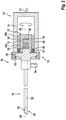
- a video endoscope 10 comprises a handle 12 and a shaft 18 connectable to each other.
- the handle 12 and the shaft 18 are shown in Figure 1 in a detached state and in Figures 2 to 4 in a connected state.
- the video endoscope 10 is designed to provide video and image data from an object field within a cavity of a non-shown body.
- the handle 12 of the video endoscope 10 is connected via a cable 11 at its proximal end to an external control and supply system providing electric power and comprising image processing and displaying means via a computer and a monitor.
- the handle 12 is only shown in a schematic longitudinal section view without any specific shape to be held by a user of the video endoscope 10, as shown in Figures 3 and 4 .
- the handle 12 of the video endoscope 10 comprises a housing 14 and an interface portion 16.
- the housing 14 has an opening in which the interface portion 16 is mounted.
- the interface portion 16 is sealed by an O-ring seal 61 in the housing 14.
- the interface portion 16 is rotatably supported by a first ball bearing 60a and a second ball bearing 60b, which are arranged between an inner surface of the housing 14 and a peripheral surface 40 of the interface portion 16 in a radial direction.
- the first ball bearing 60a is arranged between the seal 61 and a flexible circuit board 34
- the second ball bearing 60b is arranged on an opposite side of the flexible circuit board 34 at a proximal end 23 of the interface portion 16.
- the interface portion 16 respectively has a cylindric shape.
- the axis of its cylinder approximately coincides with the rotation axis 38 of the interface portion 16 and likewise with a longitudinal axis 24 of the shaft 18.
- the housing 14 comprises a reservoir 46 for receiving and storing a portion of a flexible circuit board 34.
- the interface portion 16 comprises a first connector element 26 with a plurality of sockets 30.
- the sockets 30 of the first connector element 26 are electrically connected to a PCB (printed circuit board) 35 by a multiplicity of leads (shown in Fig. 1 and 2 without reference numerals).
- the flexible circuit board 34 is arranged on the outer peripheral surface 40 of the interface portion 16, whereby a first end of the flexible board 34 is fixed to a section of the peripheral surface 40 and, at a second end, non-shown conductor tracks of the flexible board 34 are connected to the PCB 35 by non-shown leads in Figures 1 and 2 . Therefore, the PCB 35 serves as an electric transmission element between the first connector element 26 and the flexible circuit board 34.
- the handle 12 comprises at its distal end a claw coupling 13 with a claw 15 for engaging with an eyepiece cup 19 of the shaft 18.
- the elongate shaft 18 comprises a distal end 20 and a proximal end 22, whereby the longitudinal axis 24 extends between the distal end 20 and the proximal end 22 and the proximal end 22 is hermetically sealed.
- the shaft 18 comprises an imaging unit 50 including an objective lens system and an electronic image sensor.
- the imaging unit 50 is connected via a multi-wire cable 52 through the shaft to a second connector element 28 that is arranged at the proximal end 22 of the shaft 18.
- a second connector element 28 comprises a plurality of conductor pins 32, whereby only five pins 32 are shown symbolically in Figures 1 and 2 .
- the pins 32 of the second connector element 28 of the shaft 18 and the sockets 30 of the first connector element 26 are designed contrarily, whereby the pins 32 and the sockets 30 extend parallel through the rotation axis 38 of the interface portion 16 and the pins 32 can be inserted in the direction towards a proximal end 22 of the interface portion 16 into the respective sockets 30.
- the shaft 18 has an eyepiece cup 19 at its proximal end 22 and a section with a light post 54 forming a port for connecting a light cable of an external light source and a light guide (not shown) extending in the shaft 18 until the distal end 20 of the shaft 18 to transmit illumination radiation provided by the external light source towards an object field to be observed.
- This section with the light post 54 of the shaft 18 can be handled by the user of the video endoscope 10 by hand for rotation of the shaft 18.
- the shaft 18 is held by one hand and the handle 12 by the other hand by the user aligning the longitudinal axis 24 of the shaft 18 with the rotational axis 38 of the interface portion 16 of the handle 12.
- the proximal end 22 of the shaft is moved towards the distal end 17 of the handle 12.
- the pins 32 of the second connector element 28 are inserted into the respective sockets 30 of the first connector element 26 giving a mechanical and electrical connection of the shaft 18 to the handle 12.
- the first and the second connector element 26, 28 are held to each other by friction fit of the pins 32 in the sockets 30.
- the mechanical connection is secured by the claw 15 pressing the eyepiece cup 19 of the shaft 18 firmly but rotatably and releasably to the housing 14 by featuring the claw coupling 13.
- the shaft 18 Due to the form-fitted connection of the first and second connector element 26, 28 by the pins 32 and sockets 30, the shaft 18 itself is not rotatably connected to the interface portion and, therefore, the shaft 18 can only rotate together with the interface portion 16. Consequently, a rotatable and couplable video endoscope 10 is formed by the connection of the shaft 18 to the handle 12.
- the two ball bearing 60a and 60b are arranged on both sides of the flexible circuit board 34, which is spooled around the peripheral surface 40 of the handle 12 (see Figure 3 ).
- the first ball bearing 60a and the second ball bearing 60b are braced to each other in an O-modification giving two respective lines of flux 69 with two centers of pressure 51 arranged on both sides along the rotational axis 38 of the interface portion 16 and therewith outside of the connection and bearing region.
- the shaft 18 is inserted by the user of the video endoscope 10 into the cavity of the body.
- the shaft 18 is rotated by hand at the section of the light post 54 of the shaft 18 effecting a rotation of the shaft 18 together with the interface portion 16 due to the rotatable support by the two ball bearings 60a and 60b of the interface portion 16 in the housing 14 in order to achieve the desired object fields.
- the respective images captured by the electronic image sensor of the imaging unit 50 are transferred as image data via the multi-wire cable 52 through the shaft 18 to the connected second connector element 28 and further transmitted via the pins 32 and the sockets 30 of the first connector element 26 to the PCB 35, from the PCB 35 to the flexible circuit board 34 spooled around the peripheral surface 40 of the interface portion 16 and further by the cable 11 of the handle 12 to the external control and supply system to be viewed on the monitor.
- a section of the flexible circuit board 34 is unspooled into the reservoir 46.
- the first and second ball bearing 60a, 60b on both sides of the flexible circuit board 34 arranged between the housing 14 of the handle 12 and the interface portion 16 optimally absorb the forces from using the shaft 18 with centers of pressure 71 shifted to the distal end 17 of the handle and further towards the shaft 18 on one side and towards the proximal end of the handle 12 on the other side.
- a video endoscope 10 is provided with a rotatable and detachable shaft 18 and a load specific coupling due to the ball bearings 60a, 60b protecting the mechanical and electrical connection between the shaft 18 and the interface portion 16 of the handle 12 and therewith the first connector element 26, the second connector element 28 and the flexible circuit board 34 from load impact and damages.
Landscapes
- Health & Medical Sciences (AREA)
- Life Sciences & Earth Sciences (AREA)
- Surgery (AREA)
- Physics & Mathematics (AREA)
- Engineering & Computer Science (AREA)
- Optics & Photonics (AREA)
- Public Health (AREA)
- General Health & Medical Sciences (AREA)
- Veterinary Medicine (AREA)
- Pathology (AREA)
- Nuclear Medicine, Radiotherapy & Molecular Imaging (AREA)
- Animal Behavior & Ethology (AREA)
- Biomedical Technology (AREA)
- Heart & Thoracic Surgery (AREA)
- Medical Informatics (AREA)
- Molecular Biology (AREA)
- Radiology & Medical Imaging (AREA)
- Biophysics (AREA)
- Astronomy & Astrophysics (AREA)
- General Physics & Mathematics (AREA)
- Mechanical Engineering (AREA)
- Signal Processing (AREA)
- Multimedia (AREA)
- Microelectronics & Electronic Packaging (AREA)
- Oral & Maxillofacial Surgery (AREA)
- Endoscopes (AREA)
- Instruments For Viewing The Inside Of Hollow Bodies (AREA)
Abstract
Description
- The invention concerns a handle for a video endoscope, in particular for a medical or industrial video endoscope, comprising a housing and an interface portion, wherein the interface portion comprises a first connector element at its distal end, the first connector element is connected to an electric transmission element of the interface portion and is connectable to a second connector element of an associated elongate shaft of the video endoscope to form a detachable electrical and/or mechanical connection between the handle and the associated shaft, and wherein the handle comprises an electrical connection assembly arranged at an exterior of the interface portion forming an electrical connection between the electric transmission element and a stationary electric and/or electronic component of the handle. Furthermore, the invention concerns a video endoscope.
- For medical or non-medical applications, endoscopes comprise an elongate shaft configured for being introduced into an internal cavity of a human or animal body or another object for examination. For generating an image of an object field in the cavity of the body or object, an imaging optic is located in a distal (meaning distant from a user) end section of the shaft. On the opposite, proximal (meaning close to the user) end section of the shaft, a handle is attached for operating the endoscope by the user. In case of video endoscopes, which are also known as electronic endoscopes, the generated endoscopic image is picked up by an electronic image sensor, whereby, in a wide-spread design, the electronic image sensor together with the imaging optics are contained in an optic shaft arranged inside the shaft of the video endoscope. Consequently, the image signal generated by the image sensor is transmitted electronically through the shaft and the handle towards the proximal end of the video endoscope and outwards for displaying the endoscopic image on a monitor.
- Common video endoscopes are complete systems, wherein the shaft and the handle are permanently fixed to each other. As a complete system, the whole video endoscope must be cleaned and sterilized (generally in an autoclave) after each use. Furthermore, during an endoscopic procedure, user is frequently required to change a rotational orientation of the endoscope in order to vary the view of the object field, and in with the limitations of conventional video endoscopes, the complete video endoscope must be rotated during examination. As such, the operator controls, buttons or touch keys, which are usually arranged at the top side of the handle in its upright position, are arranged in an unfavorable position for the user during rotation. This design is especially disadvantageous, because normally the handle is held by the same hand of the user that likewise operates the operator buttons or touch keys.
- As, in a video endoscope, the electronic image sensor is stationary and generally mounted in the shaft, most commonly at the distal end of the shaft, the image sensor will always rotate together with the rotation of the shaft, while, from a user point of view and for ergonomic reasons, it would be preferable to keep an orientation of the handle unchanged during the rotation of the shaft, as is generally the case with proximal detection endoscopic systems, where the image light is transmitted through the shaft, and detected by a sensor contained within the handle or camera head element. While in certain systems, problems associated with the rotation of an image displayed to the user as a result of the rotating sensor can be solved, as is known in the art, by an image processing unit configured for erecting the image displayed on the viewing monitor, in contrast the rotation of the handle itself remains disadvantageous.
-
US 2017/0209024 A1 discloses an endoscopic device which comprises a shaft including a controllable bend, a lumen and a controllable channel moveably set in the lumen as well as a handle including a controller selectively engageable with the controllable bend and the controllable channel. Inside the shaft, actuators are housed including each an opposing pair of motorized rollers mounted in the lumen for translational movement of the control channel in the proximal or distal direction as well as for rotational movement. Therefore,US 2017/0209024 A1 only concerns the movement and rotation of a control channel relative to a lumen by respectively arranged rollers. - In
US 10,365,470 B2 US 10,365,470 B2 - The objective of the present invention is to improve the known state of the art.
- The problem is solved by a handle for a video endoscope, in particular for a medical or industrial video endoscope, comprising a housing and an interface portion, wherein the interface portion comprises a first connector element at its distal end, the first connector element is connected to an electric transmission element of the interface portion and is connectable to a second connector element of an associated elongate shaft of the video endoscope to form a detachable electrical and/or mechanical connection between the handle and the associated shaft, and wherein the handle comprises an electrical connection assembly arranged at an exterior of the interface portion forming an electrical connection between the electric transmission element and a stationary electric and/or electronic component of the handle, wherein the handle comprises at least a first bearing for rotatably supporting the interface portion in and/or at the housing so that, in case of a connection between the associated shaft and the handle, the associated shaft is rotatable via the rotatably supported interface portion relatively to the housing of the handle. Therefore, a handle for a video endoscope is provided which permits improved handling and orientation of the video endoscope for a user, especially such that the user can operate the handle of the video endoscope in a manner to which the user has been accustomed. It is particularly beneficial that the orientation of the handle stays essentially constant and, therefore, the operator controls and the handle and its housing are not required to rotate with the rotation of the connected shaft. Therefore, the use of the video endoscope and the navigation by the user inside a body cavity is improved by the inventive handle. Consequently, an endoscopic procedure can be prolonged, and the risk involved in a medical endoscopic intervention is reduced.
- As the shaft is connectable via its second connector element to the first connector element of the interface portion of the handle, whereby the interface portion is rotatably supported inside the housing of the handle, the shaft is rotatable together with the interface portion independently and relative to the housing of the handle and therewith independently of the static orientation of the handle. Thus, an efficient and user-friendly handle for a video endoscope is provided, such that a distal tip sensor video endoscope may be handled in a manner similar to traditional endoscopes with a proximal sensor located in an attached camera head.
- In addition to allowing the rotation of the video endoscope shaft relative to the instrument handle, the rotatable coupling point comprising the second connector element of the shaft and the first connector element of the interface portion of the handle, also enables a modular video endoscope to be free from the necessity of a permanent, fixed connection between the shaft and the handle. This modular design provides a higher flexibility for the user. In particular, the modular handle is connectable to different shafts with different properties, such as shaft diameter or optical properties, or the same kind of shaft in between individual medical interventions, or during one intervention. Thus, due to the rotatable and connectable interface between the handle and the shaft of a video endoscope, different shafts may be coupled to a single handle, and, alternatively, multiple handles may be connected to the same shaft. Consequently, the shaft is separately cleanable, autoclavable and exchangeable without similar treatment of the handle, whereby the latter is normally not inserted into the cavity of the body and therefore does not require the same cleaning, disinfection and/or sterilization procedures as the shaft.
- Given that the electrical and/or mechanical connection of the shaft to the handle is formed inside the handle, and the rotation of the shaft is rotatably supported by the interface portion by means of the at least one bearing, a more generalized and simpler design of the shaft is enabled. Furthermore, as the shaft is detachably connected to the handle, the shaft itself can also be designed to be disposable, while the handle may be reused. This configuration permits the optimization of expense relating to disposable elements by including more costly, but required, elements to be housed in the reusable handle, while the shafts may include only the elements necessary for their function.
- Certainly, the invention is not limited to a constant orientation of the handle, also the reverse arrangement is possible where the position of the shaft is hold essentially constant while the handle is rotated. Even the handle and the shaft both can be rotated simultaneously in relation to each other.
- Overall, a higher flexibility for the user concerning the exchangeability of the shaft to the modular handle as well as concerning the rotation of the shaft depending on the object field and the preferred hand movement of the user is provided.
- One of the primary elements of the invention includes a handle and a video endoscope with a connectable and detachable coupling point between the handle and the shaft of the video endoscope, whereby rotation of the shaft is accomplished independently from the orientation of the handle by supporting the coupling interface portion, to which the shaft is connectable via the second connector element to the first connector element of the interface portion, rotatable via at least one bearing in, at and/or inside the housing of the handle.
- As utilized in accordance with the present disclosure, the following terms, unless otherwise indicated, shall be understood to have the following meanings.
- In particular, a "video endoscope" (also denominated simply "endoscope") is an endoscope with digital image acquisition and transmission in to the proximal end. The video endoscope comprises a shaft and a handle which are connectable to each other. At least one digital image sensor is located at the distal end of the elongated shaft for image acquisition. A "video endoscope" is any kind of digital endoscope, for example a mediastinoscope, but may also include non-medical scopes used for industrial purposes, often called borescopes.
- The "elongated shaft" is in particular a rigid tube, and therefore, the video endoscope may be a rigid endoscope, or, as well, the shaft may be formed by a flexible tube and therefore, a flexible video endoscope is provided. In particular, the shaft is configured for being inserted into a cavity to be viewed endoscopically, for example, to be inserted into a body cavity of a human or animal body or another opening in industrial applications, for example, a pipe. The shaft generally may have an outer diameter in the range of 4 mm to 10 mm. The shaft may comprise one or more channels for irrigation and/or through which working instruments may pass (generally referred to as "working channels") in order to achieve a desired effect in cavity or opening. Preferably, at its distal end, the shaft comprises an electronic image sensor arranged for picking up an image of an object field, whereby the image is generated by an objective lens system. The objective lens system can be arranged at or in a distal end section of the shaft, such that the image is generated on an image sensing surface of the image sensor. The electronic image sensor may be, for example, a charge-coupled device (CCD) or a complementary metal-oxide semiconductor (CMOS). Preferably, the image sensor is configured to convert the captured image into an electrical image signal.
- The electronic image sensor, preferably arranged in the distal end section of the shaft, transmits the electrical image signals from the distal end section of the shaft to its proximal end by electrical transmission lines, such as wires, cables and/or a flexible printed circuit board. The transmission is preferably bidirectional, such that electric energy can be supplied and/or control signals transferred to the electronic image sensor. In addition, the generated electrical image signals can be transferred from the electronic image sensor to the proximal end section of the shaft and/or further to the handle and/or an external monitor. Additionally, the bidirectional electrical connection may supply power, in some embodiments, to distally placed illumination means, such as light emitting diodes.
- Alternatively, the image sensor may also be positioned in the proximal end section of the shaft and image light collected by the objective lens system may propagate from the distal end section of the shaft to the proximal end section, where the image sensor picks up the image transferred. In this alternative, the shaft comprises a suitable optical image transmission system including, for example, rod lenses for transferring the image light from the distal end section of the shaft to the proximally located image sensor.
- Certainly, the video endoscope and/or the shaft may also comprise more than one image sensor being distally or proximally located or even a multiplicity of image sensors, for example three or more image sensors. Multiple image sensors being particularly useful for performing stereo endoscopy, and, in particular, dual image sensors being advantageous for the generation of 3D images.
- For the detachable connection to the handle, the shaft comprises at its proximal end section preferably a second connector element. Preferably, the shaft is connected at its proximal end via the second connector element to the first connector element of the interface portion of the handle. In particular, the "first connector element" by the handle and the "second connector element" by the shaft are formed as corresponding counterparts. Especially, the first connector element and the second connector element are each formed in such a manner, that both parts together provide a form-locking connection. For example, the second connector element can be formed as plug and/or male connector and the first connector element can be formed as a female connector and/or a plug socket or vice versa. The first connector element and the second connector element are preferably arranged to be able for a bidirectional transmission.
- In particular, the first and second connector elements are configured for transmitting the electric image signal generated by the electronic image sensor to the electric transmission element of the interface portion and for transmitting electric energy and/or control signals from the electric transmission element to the electronic image sensor arranged in the shaft. Consequently, the first and second connector elements are configured for electrically connecting the electric transmission element of the interface portion to the electronic image sensor via a detachable electrical interface.
- The coupling point formed by the first connector element and the second connector element preferably enables a non-rotatably connection of the shaft to the interface portion of the handle. Consequently, the shaft is rotatable only in conjunction with the interface portion with respect to the housing and therefore rotatable around the rotational axis of the interface portion relative to the housing. Preferably, the shaft is connectable via the coupling point to the interface portion in such a manner, that a longitudinal axis of the shaft is substantially aligned with the rotational axis of the interface portion, so that the shaft is rotatable around its longitudinal axis together with the interface portion relative to and therefore independent from the orientation of the housing of the handle. Alternatively, the shaft may be configured and the second connector element located such that the longitudinal axis of the shaft forms an angle to the rotational axis of the interface portion.
- A "detachable electrical and/or mechanical connection" particularly means that the shaft and the handle can be easily separated and disconnected from each other. In particular, the shaft can be detached from the interface portion and therefore the handle without use of any tool and, more preferably, easily by hand of the user immediately before, during or after an endoscopic intervention or examination.
- A "handle" is, in particular, an object that can be moved and/or used by hand, enabling the user to exploit the connected tool and/or instrument for its function. A handle is especially a part of a video endoscope. In particular, the handle comprises a housing and an interface portion which is mounted rotatably via at least one first bearing relative to the housing. Especially, the handle is a modular handle, which can be connected to different kinds of shafts to provide a video endoscope. The handle enables the user to grab, hold and/or operate and manipulate the connectable shaft and therefore the video endoscope. The handle may comprise a grip or grip portion to facilitate holding the handle by the user. Preferably, at its outer surface, for example on the top side or a side face, the handle comprises one or more control elements, such as user buttons or touch keys, for controlling various functions of the endoscope. Preferential, the control elements are arranged and/or located in such a manner on and/or in the surface of the handle that the user can operate the control elements with one or more fingers of the same hand which is holding the handle.
- The "interface portion" is a separate part of the handle which is rotatably mounted relative to the housing of the handle. The interface portion has an exterior, which may be an outer surface of a body of the interface portion. In particular, the exterior of the interface portion may be formed by an outer surface of the interface portion in such a way that a proximally rotational symmetry with respect to the rotational axis is given. The exterior may be or comprise a continuous face or may be discontinuous, for example having a grid surface. The interface portion might be formed from solid material. The interface portion may comprise an interior hollow space for including the electric transmission element or other parts. For example, the interface portion can be formed as a hollow cylinder with one face side or both face sides closed. Preferably, at the distal end and/or at and/or inside the distal end section of the interface portion, the first connector element is arranged.
- Additionally, at its distal end or end section, the interface portion and/or the housing of the handle may comprise a claw for forming a claw coupling. Preferably, the interface portion is mounted and supported by at least one bearing in the housing. Hereby, the interface portion may be mounted partially or completely inside the housing, for example in an opening or a partially open cavity of the housing. Therefore, the interface portion may be covered by the housing completely besides the distal face side with the attached first connector element. Alternatively, the interface portion could be mounted in such a manner, that at least a section of its exterior forms a part of an exterior of the handle. However, at least a section of the exterior of the interface portion or the majority of the interface portion may be enclosed or encompassed by the housing of the handle.
- The "transmission element" is an electric and/or electronic element to which the first connector element is electrically connected. Furthermore, the electric transmission element is particularly connected to the electrical connection assembly arranged at an exterior of the interface portion. Thus, the electric transmission element is an intermediate element for transmission of electric energy and/or signal and/or control data between the first connector element and the electrical connection assembly, whereby, from the electrical connection assembly, the signal data is transferred further to the stationary electric and/or electronic component. Reversely, the electric power and/or control signals are transmitted from the stationary electric and/or electronic component via the electrical connection assembly to the electric transmission element of the interface portion and further via the first connector element and the second connector element towards the shaft. Therewith, the first and second connector elements are cooperating and being connected to form a detachable electric connection between the electric transmission element of the interface portion and the electronic image sensor in the shaft. The electric transmission element of the interface portion may be, for example, one or several cables, a multi-wire cable or a printed circuit board (PCB) having conductor tracks for transmitting electric signals and/or energy. Preferably, the interface portion, apart from the electric transmission element and the electrical connection assembly, comprises no further electric or electronic parts and no control and/or processing element. Alternatively, the electronic transmission element of the interface portion may comprise image pre-processing circuitry or other components.
- An "electrical connection assembly" is an electric component for featuring an electric connection between the interface portion and a stationary electric and/or electronic component. The electrical connection assembly comprises at least one electric component or several electric components. The electrical connection assembly is configured for transmission of the electric image signals from the electric transmission element of the interface portion to the stationary electronics of the handle, and/or for transmitting electric energy and/or control signals from the stationary electronics of the handle to the electric transmission element of the interface portion. In particular, the electrical connection assembly is arranged at the exterior of the interface portion and forms an electrical connection in a multiplicity of rotational positions of the interface portion relative to the housing. Hereby, the electrical connection assembly is configured to maintain the electrical connection in various rotational positions of the interface portion to the housing without interruption. In particular, the electrical connection assembly may be configured to provide the electric connection independently from the rotational position or from a corresponding rotation angle of the interface portion, at least in a given range of rotational positions. Consequently, the electrical connection assembly forms an electrical connection between the electric transmission element of the rotatable or rotating interface portion and the stationary, non-rotatable electronics of the handle. Preferably, the electrical connection assembly is configured in such a manner, that it copes with the rotational movement of the interface portion without permitting an influence of the rotation on the electrical connection and, therefore, guaranteeing a high-quality connection. The electrical connection assembly may have a first end or part that its connected to or is configured to contact the exterior, for example connected to or connecting an outer surface, of the interface portion and a second ends or element that is connected to the stationary electronics of the handle, wherein the first and second end are electrically connected or contacted to each other. For example, the electrical connection assembly can be a sliding contact consisting of a brush and a slip ring or may be a flexible conductor element, such as a flexible ribbon cable or a flexible circuit board.
- A "bearing" is, in particular, a machine element that constrains relative motion to only the desired motion and reduces the friction between moving and/or stationary parts. The bearing may provide free rotation of the interface portion around its rotational axis and/or the rotational axis of the bearing. In particular, the bearing is a rotary bearing which holds and supports the interface portion at and/or in the housing. The bearing is, for example, a rolling element bearing or a plain bearing. For supporting the interface portion in the housing, it is possible to use only one bearing, e.g. a plain bearing, where the other part of the bearing is formed by the interface portion or the housing.
- In a further embodiment, the handle comprises a second bearing for rotatably supporting the interface portion, wherein the first and the second bearings are arranged in a distance to each other in a direction along a rotation axis of the interface portion.
- Thus, a load specific, rotatable support of the interface portion in the housing is provided. Hereby, the load by the connectable shaft can be absorbed and distributed by two bearings improving a smooth rotating of the shaft and the electrical and/or mechanical connection between the shaft and the interface portion. Consequently, a rotatable, reliable transmission of supplied energy and signal as well as control data is guaranteed.
- The "second bearing" is a bearing as defined above.
- A "rotation axis" is, in particular, a straight line around which a body can rotate without changing the view of the body. Preferably, the rotation axis is also an axis of symmetry of the body. The rotation axis of the interface portion can be identical to the rotation axis of the center of the first and/or second bearing. Likewise, the rotation axis of the interface portion can be identical to the longitudinal axis of the interface portion and/or the shaft.
- In order to fit the first and/or second bearing tightly between the housing and the interface portion of the handle and/or to specifically surround a cylindric interface portion, the first and/or the second bearing comprises or comprise an outer ring surface and an inner ring surface, wherein the outer ring surface is arranged at an inner surface of the housing and the inner ring surface is arranged at an outer peripheral surface of the interface portion.
- Thus, the outer ring surface is stationary attached to the housing, while the inner ring surface rotates, allowing the rotation of the supported interface portion at the inner ring surface and therefore the rotation of the connectable shaft. In case of a cylindric interface portion, preferably the inner ring surface is arranged directly around the outer peripheral surface of the cylindric interface portion for rotating the interface portion and the connectable shaft. Alternatively, the interface portion comprises a drive shaft, which is supported by the bearing or bearings. Certainly, one bearing or the bearings can also be arranged such, that the shaft is fixed in its orientation and the handle is rotatable or that the shaft and the handle can be both rotated simultaneously relative to each other.
- In yet another embodiment of the invention, the first and/or second bearing is and/or are rolling-element bearing and/or a plain bearing.
- Therefore, the interface portion can be rotatably supported in the housing by a rolling-element bearing alone or a plain bearing alone or by two rolling-element bearings, two plain bearings or a mixed support by one rolling-element bearing and one plain bearing. As a plain bearing mostly takes radial forces, two rolling-element bearings can be more advantageous in case of high loads by the shaft and for reducing friction losses. In particular, the advantages of ball bearings are that this kind of bearings can absorb likewise radial and/or axial forces.
- A "rolling-element bearing" is a bearing in which rolling-elements are placed between the turning and the stationary races preventing sliding friction. A rolling-element bearing can be a bearing in which the rolling-elements are spherical balls. Likewise, a rolling-element bearing can be a roller bearing, in which the rolling-elements are cylindrical, tapered and/or spherical rollers.
- A "plain bearing" is, in particular, a bearing consisting of a shaft rotation in a hole. In a plain bearing, especially the shaft is sliding over and/or rotating relative to the bearing surface. In case of a plain bearing, either the shaft is connected to the interface portion, for example to the face side of the interface portion at the proximal end, or the interface portion itself constitutes the shaft and slides directly inside the surrounding bearing surface of the plain bearing.
- As forces acting on the electrical and/or mechanical connection between the shaft and the interface portion of the handle result mostly from the movement of the shaft in the cavity during use of the video endoscope, the first or the second bearing has a length in the direction along the rotational axis of the interface portion in such a manner or the distance between the first and the second bearings is arranged in such a manner, that the load force from outside the bearing or bearings is absorbable by the bearing or bearings.
- Therefore, in case of one plain bearing, the length of the plain bearing in the direction along the rotation axis of the interface portion can be adapted, so that forces from the shaft and especially a lever action are minimized and/or absorbed. Likewise, two bearings can be arranged in an optimal distance to each other for best taking of the acting forces during the use of the video endoscope.
- Various shaft lengths may be used according to the present invention, depending on bearing positions. As an example, in certain implementations, a center-to-center distance between the bearings might be 23.5mm, and such a configuration might correspond to a complete shaft length (from the end of the bearing to the distal tip of the shaft) of 370mm and a functional shaft length (from the end of the clasping mechanism to the distal tip of the shaft) of 300 mm, that is, the bearing distance is approximately 5.14% of the complete shaft length and 7.38% of the functional shaft length in this example.
- In another embodiment of the invention, the first and the second bearings are mounted in an O-modification, so that a center of force is shifted towards the associated elongate shaft and/or a proximal end of the handle protecting the first connector element, the second connector element and/or the electrical connection assembly of the handle.
- Therewith, load specific coupling point bearings are provided which connect the rotatable interface portion and/or shaft with the housing of the handle and simultaneously protecting the electrical and/or mechanical connection between the shaft and the handle as well as the electrical connection assembly of the handle from too high forces.
- By bracing the two bearings towards each other, an O-modification is achieved with force flow lines surrounding the first connector element, the second connector element and/or the electrical connection assembly, whereby the center of pressure of the video endoscope is further extended along its shaft. Consequently, the load on the first and second connector element as well as on the electrical connection assembly is decreased and forces from outside the bearing region are optimally absorbed. In case of a video endoscope with a rigid shaft, greatest forces typically act at its distal end. By the O-modification, the load bearing points are moved to the load application points as close as possible. Therefore, the point of load application and the point of load bearing are located outside the bearing regions and preferably close together. The point of load application is located at the shaft of the video endoscope and the point of load bearing is also shifted towards the shaft, notwithstanding that the bearing itself is realized in the handle.
- Due to the optimal absorption of the load by the bearings, especially in the O-modification, the attached shaft can be more easily rotated relative to the handle. Thus, the connected shaft can be rotated easily and quickly by the user in the cavity during an intervention and use maintaining an upright, vertical position of the handle.
- For an optimal load protection of the electrical connection assembly, the first bearing and the second bearing are located on both sides of the electrical connection assembly arranged at the exterior of the interface portion or the outer periphery surface of the interface portion.
- In a further embodiment of the handle, the housing comprises a seal for sealing the interface portion at its distal end in the housing.
- Therefore, the seal is provided to seal an opening of the housing, in which the interface portion is rotatably mounted. Preferably, the seal is located adjacent to a bearing, such that the bearings are comprised in a sealed inner space of the housing. Most preferably, the seal is arranged at an outside direction from the first and second bearings, such that the region of the outer peripheral surface and/or the electrical connection assembly is enclosed by the seal. Such a seal can protect the handle, particularly any electric and electronic components and/or connections within the handle and/or the interface portion, such as, in particular, the electrical connection assembly, from body liquid, other liquids and/or sterilization fluids. Therefore, the sealing may improve the durability and operational safety of the handle and the video endoscope.
- For an optimal bracing of the bearings and therefore optimal protection by the bearings, the first bearing is located between the seal and the electrical connection assembly and/or the second bearing is located at a proximal end of the interface portion.
- In a further embodiment of the handle, the electrical connection assembly comprises at least one flexible conductor element.
- By the flexible conductor element, a flexible and therefore moveable connection is provided between the electric transmission element and a stationary electric and/or electronic component of the handle. Further, this electrical connection can be maintained in a multiplicity of rotational positions of the shaft or, in particular, in any orientation of the shaft relative to the housing of the handle.
- A "flexible conductor element" is, in particular, a flexible ribbon cable, a flexible elongate circuit board and/or any other flexible electric connection. The flexible conductor element can be twisted around its longitudinal direction and/or can be spooled. A ribbon cable or a flexible circuit board may comprise a multiplicity of electric leads, permitting transmission of a high data volume and/or several signals in parallel, as well as supplying energy to the image sensor in the shaft.
- For allowing a simple, reliable and reproduceable electric connection of the handle and therefore reliable and reproduceable operation of the video endoscope, the at least one flexible conductor element is configured to be spooled on and/or unspooled from the exterior or outer peripheral surface of the interface portion by rotating the interface portion relative to the housing.
- By this embodiment, the rotatability is electrically realized by the spooling and/or unspooling of the flexible conductor element, such as a flexible circuit board, around and/or from the outside of the interface portion, whereby the flexible conductor element is the intermediate electrical connection element between the first connector element and the electric transmission element on the distal side of the handle and the stationary electric and/or electronic component of the handle. Consequently, the user is free to choose a suitable orientation of the shaft without substantially impeding the electrical connection between the image sensor in the shaft and an image processing unit connected to the stationary electric component arranged in the handle or outside the handle.
- In particular, the flexible conductor element is wrapped or wound around the section of the periphery or the outer peripheral surface of the interface portion or a respective frame or spool arranged at the outside of the interface portion, when the interface portion is rotated by handling the shaft in one direction, and wound off when the interface portion is rotated in the opposite direction. Hereby, the interface portion and the flexible conductor element can directly form a spool.
- The flexible conductor element may have a first end that is fixed to the outer peripheral surface and electrically connected to the electric transmission element of the interface portion, and a second end that is mounted to the housing and connected to the stationary electric and/or electronic component of the handle. Most preferably, the flexible conductor element is mounted and/or arranged such that a twisting is avoided when it is spooled or unspooled. Consequently, the electric connection can be maintained by the flexible conductor element in an uninterrupted manner during rotation and for any rotational position of the interface portion in a pre-defined range of rotational positions under low friction forces. Preferably, the interface portion or the flexible conductor element are configured such that the flexible conductor element can be wound at least 90 °, at least 180 °, at least 270 ° or at least 360 ° around the outer periphery of the interface portion, at least a rotation is permitted in a corresponding range of rotational positions. Hereby, the flexible conductor element may carry out more than one complete winding when it is wound around the circumference of the interface portion or may form one complete winding or more than one winding. Preferably, in case of several windings, each winding may be wound one on the other, forming a spiral-shaped arrangement. Consequently, a high degree of rotational freedom and a substantially whirl-free operation of the handle and therefore enhanced functionality and durability of the video endoscope is provided.
- As the flexible conductor element can be spooled around the outer surface of the interface portion and/or arranged between the space between the two bearings as a reservoir, a space-saving arrangement and therefore a compact and ergonomic design of the handle is achieved. Accordingly, the video endoscope permits easier handling and configuration as well as improved functionality and operational safety.
- Preferably, the flexible conductor element is completely contained in the housing of the handle, especially in a provided sufficient space in a reservoir. Furthermore, for avoiding entangling or blocking of the flexible conductor element during spooling and/or unspooling, the flexible conductor element is guided by a guidance mean, such as a roll.
- In yet another embodiment, the handle comprises at its distal end a claw coupling for holding a coupling plate, in particular eyepiece cup, of the associated shaft and for securing the connection between the associated shaft and the handle.
- In the connected state, the coupling plate and/or the eyepiece cup is pressed by the claw and therewith the complete shaft against the interface portion. By this mechanical claw coupling, an additional mechanical connection with a greater connecting surface than the first and the second connector elements is provided. Consequently, the shaft is additionally secured at the housing and/or interface portion of the handle.
- A "claw coupling", also called dock-clutch, is in particular a clutch that couples two components, whereby at least one or both components are rotatable, by interference or clearance fit. Preferably, the claw of the claw coupling is designed such that the coupling plate and/or the eyepiece cup is pushed towards the interface portion, while both the shaft with the coupling plate and/or eyepiece cup and the interface portion are rotating at the same speed without slip.
- In an additional aspect of the invention, the problem is solved by a video endoscope, in particular medical or industrial video endoscope, comprising an elongate shaft, wherein the elongate shaft comprises at least one electronic image sensor, a second connector element at a proximal end section of the shaft, which is electrically connected to the at least one electronic image sensor and is detachably connected to a handle, and/or a coupling plate, wherein the handle is a handle as described above, so that the first connector element of the handle and the second connector element of the handle form a detachable electrical and/or mechanical connection and the shaft is rotatable via the rotatably supported interface portion relatively to the housing of the handle.
- Therewith, a rotatable and connectable video endoscope is provided with a load specific support of the shaft at and/or in the handle including load specific bearings for the rotatability.
- Certainly, the handle is not restricted to a specific kind of video endoscope and can be connected to any kind of shaft for forming the video endoscope or a conventional endoscope. Besides that, the handle can be used to form any kind also of conventional endoscopes, the handle is specifically designed for forming a video endoscope with each connected shaft.
- Therefore, a video endoscope is provided which can be used and operated by the handle in an easy and efficient way by the user.
- In a further embodiment of the video endoscope, the first connector element of the interface portion of the handle and the second connector element of the shaft form a bidirectional electric connection.
- Thus, control signals and energy can be transmitted from the handle of the video endoscope to the shaft and the image sensor located in the shaft and reversely image signals and data can be transferred from the shaft to the handle and further to the outside of the video endoscope.
- Therefore, electronic image data can be transferred bidirectionally via the rotatable, electric connection between the handle and the shaft.
- In a further aspect of the invention, the problem is solved by a connectable and detachable shaft as described above to the handle.
- As the bearing concept of the invention is realized in the handle of the couplable endoscope, the shaft can be realized more generalized and/or permits a simpler, disposable design. Furthermore, the shaft can be disconnected and reused and can undergo a special disinfection and/or sterilization treatment independent from the handle. For this, especially the proximal end of the shaft is hermetically sealed and therefore in particular autoclavable allowing multiple use of the shaft.
- Alternatively, the shaft may be configured disposable and therefore for single use. In particular, the shaft may comprise only a small number of costly optical and electronic elements and thus may be designed to be manufactured at comparatively low costs.
- In contrast, the handle is configured normally for multiple use, as the handle is not introduced into the cavity of a body during the endoscopic intervention, the handle does not necessarily have to be autoclavable.
- In a further aspect of the invention, the problem is solved by a method for configuring a video endoscope, including the steps of providing a handle and a shaft being configured as described above, wherein the shaft is connected to the handle electrically and mechanically, as described above, to form the video endoscope to be operatable.
- In a subsequent method step to be performed after the use of the video endoscope, the shaft may be detached from the handle as described above. In a further step, another shaft may be connected to the handle or the shaft and the handle may be subject to cleaning and/or sterilization. Both the shaft and the handle may be reusable, the shaft preferably autoclavable.
- The invention is further explained by the following exemplary description of particular embodiments. The figures show:
- Figure 1
- a schematical partially sectional view of a shaft and a handle of a video endoscope in a detached state,
- Figure 2
- a schematical sectional view of the video endoscope of
Figure 1 in a connected state, - Figure 3
- a three-dimensional view of a cross-section of the shaft and the handle of the video endoscope in a connected state, and
- Figure 4
- a detail of the cross-section of the shaft connected to the handle with two ball bearings in O-modification.
- A
video endoscope 10 comprises ahandle 12 and ashaft 18 connectable to each other. Thehandle 12 and theshaft 18 are shown inFigure 1 in a detached state and inFigures 2 to 4 in a connected state. Thevideo endoscope 10 is designed to provide video and image data from an object field within a cavity of a non-shown body. Thehandle 12 of thevideo endoscope 10 is connected via acable 11 at its proximal end to an external control and supply system providing electric power and comprising image processing and displaying means via a computer and a monitor. - In
Figures 1 and2 , thehandle 12 is only shown in a schematic longitudinal section view without any specific shape to be held by a user of thevideo endoscope 10, as shown inFigures 3 and4 . Thehandle 12 of thevideo endoscope 10 comprises ahousing 14 and aninterface portion 16. At adistal end 17 of thehandle 12, thehousing 14 has an opening in which theinterface portion 16 is mounted. Hereby, theinterface portion 16 is sealed by an O-ring seal 61 in thehousing 14. - The
interface portion 16 is rotatably supported by afirst ball bearing 60a and a second ball bearing 60b, which are arranged between an inner surface of thehousing 14 and aperipheral surface 40 of theinterface portion 16 in a radial direction. In a direction of therotation axis 38 thefirst ball bearing 60a is arranged between theseal 61 and aflexible circuit board 34, while thesecond ball bearing 60b is arranged on an opposite side of theflexible circuit board 34 at aproximal end 23 of theinterface portion 16. Theinterface portion 16 respectively has a cylindric shape. By the twoball bearings interface portion 16 is rotatably supported relative to thehousing 14. By the cylindric shape of theinterface portion 16, the axis of its cylinder approximately coincides with therotation axis 38 of theinterface portion 16 and likewise with alongitudinal axis 24 of theshaft 18. - Between both
ball bearings housing 14 comprises areservoir 46 for receiving and storing a portion of aflexible circuit board 34. - At its distal end, the
interface portion 16 comprises afirst connector element 26 with a plurality ofsockets 30. Thesockets 30 of thefirst connector element 26 are electrically connected to a PCB (printed circuit board) 35 by a multiplicity of leads (shown inFig. 1 and2 without reference numerals). Further, for the electric connection, theflexible circuit board 34 is arranged on the outerperipheral surface 40 of theinterface portion 16, whereby a first end of theflexible board 34 is fixed to a section of theperipheral surface 40 and, at a second end, non-shown conductor tracks of theflexible board 34 are connected to thePCB 35 by non-shown leads inFigures 1 and2 . Therefore, thePCB 35 serves as an electric transmission element between thefirst connector element 26 and theflexible circuit board 34. - Furthermore, the
handle 12 comprises at its distal end aclaw coupling 13 with aclaw 15 for engaging with aneyepiece cup 19 of theshaft 18. - The
elongate shaft 18 comprises adistal end 20 and aproximal end 22, whereby thelongitudinal axis 24 extends between thedistal end 20 and theproximal end 22 and theproximal end 22 is hermetically sealed. At itsdistal end 20, theshaft 18 comprises animaging unit 50 including an objective lens system and an electronic image sensor. Theimaging unit 50 is connected via amulti-wire cable 52 through the shaft to asecond connector element 28 that is arranged at theproximal end 22 of theshaft 18. Asecond connector element 28 comprises a plurality of conductor pins 32, whereby only fivepins 32 are shown symbolically inFigures 1 and2 . Thepins 32 of thesecond connector element 28 of theshaft 18 and thesockets 30 of thefirst connector element 26 are designed contrarily, whereby thepins 32 and thesockets 30 extend parallel through therotation axis 38 of theinterface portion 16 and thepins 32 can be inserted in the direction towards aproximal end 22 of theinterface portion 16 into therespective sockets 30. - Furthermore, the
shaft 18 has aneyepiece cup 19 at itsproximal end 22 and a section with alight post 54 forming a port for connecting a light cable of an external light source and a light guide (not shown) extending in theshaft 18 until thedistal end 20 of theshaft 18 to transmit illumination radiation provided by the external light source towards an object field to be observed. This section with thelight post 54 of theshaft 18 can be handled by the user of thevideo endoscope 10 by hand for rotation of theshaft 18. - For connecting the
shaft 18 to thehandle 12, the following steps are carried out: - The
shaft 18 is held by one hand and thehandle 12 by the other hand by the user aligning thelongitudinal axis 24 of theshaft 18 with therotational axis 38 of theinterface portion 16 of thehandle 12. Theproximal end 22 of the shaft is moved towards thedistal end 17 of thehandle 12. Guided by theclaw coupling 13 with theclaw 15, thepins 32 of thesecond connector element 28 are inserted into therespective sockets 30 of thefirst connector element 26 giving a mechanical and electrical connection of theshaft 18 to thehandle 12. Hereby, the first and thesecond connector element pins 32 in thesockets 30. Furthermore, the mechanical connection is secured by theclaw 15 pressing theeyepiece cup 19 of theshaft 18 firmly but rotatably and releasably to thehousing 14 by featuring theclaw coupling 13. Due to the form-fitted connection of the first andsecond connector element pins 32 andsockets 30, theshaft 18 itself is not rotatably connected to the interface portion and, therefore, theshaft 18 can only rotate together with theinterface portion 16. Consequently, a rotatable andcouplable video endoscope 10 is formed by the connection of theshaft 18 to thehandle 12. - The two
ball bearing flexible circuit board 34, which is spooled around theperipheral surface 40 of the handle 12 (seeFigure 3 ). Thefirst ball bearing 60a and the second ball bearing 60b are braced to each other in an O-modification giving two respective lines offlux 69 with two centers of pressure 51 arranged on both sides along therotational axis 38 of theinterface portion 16 and therewith outside of the connection and bearing region. - The
shaft 18 is inserted by the user of thevideo endoscope 10 into the cavity of the body. Hereby, theshaft 18 is rotated by hand at the section of thelight post 54 of theshaft 18 effecting a rotation of theshaft 18 together with theinterface portion 16 due to the rotatable support by the twoball bearings interface portion 16 in thehousing 14 in order to achieve the desired object fields. The respective images captured by the electronic image sensor of theimaging unit 50 are transferred as image data via themulti-wire cable 52 through theshaft 18 to the connectedsecond connector element 28 and further transmitted via thepins 32 and thesockets 30 of thefirst connector element 26 to thePCB 35, from thePCB 35 to theflexible circuit board 34 spooled around theperipheral surface 40 of theinterface portion 16 and further by thecable 11 of thehandle 12 to the external control and supply system to be viewed on the monitor. By the respective clockwise rotation of theshaft 18 and theinterface portion 16, a section of theflexible circuit board 34 is unspooled into thereservoir 46. - Due to the arrangement and bracing of the
first ball bearing 60a and the second ball bearing 60b in an O-modification with the respective lines of flux 66, the first and second ball bearing 60a, 60b on both sides of theflexible circuit board 34 arranged between thehousing 14 of thehandle 12 and theinterface portion 16 optimally absorb the forces from using theshaft 18 with centers ofpressure 71 shifted to thedistal end 17 of the handle and further towards theshaft 18 on one side and towards the proximal end of thehandle 12 on the other side. - Therefore, a
video endoscope 10 is provided with a rotatable anddetachable shaft 18 and a load specific coupling due to theball bearings shaft 18 and theinterface portion 16 of thehandle 12 and therewith thefirst connector element 26, thesecond connector element 28 and theflexible circuit board 34 from load impact and damages. -
- 10
- Video endoscope
- 11
- Cable
- 12
- Handle
- 13
- Claw coupling
- 14
- Housing
- 15
- Claw
- 16
- Interface portion
- 17
- Distal end of handle
- 18
- Shaft
- 19
- Eyepiece cup
- 20
- Distal end of shaft
- 22
- Proximal end of shaft
- 23
- Proximal end of interface portion
- 24
- Longitudinal axis
- 26
- First connector element
- 28
- Second connector element
- 30
- Socket
- 32
- Pin
- 34
- Flexible circuit board
- 35
- PCB
- 38
- Rotation axis
- 40
- Peripheral surface
- 46
- Reservoir
- 50
- Imaging unit
- 52
- Cable
- 53
- Leads
- 54
- Light post
- 60a
- First ball bearing
- 60b
- Second ball bearing
- 61
- Seal
- 67
- Distance
- 69
- Line of flux (O-modification)
- 71
- Center of pressure
Claims (14)
- Handle (12) for a video endoscope (10), in particular for a medical or industrial video endoscope, comprising a housing (14) and an interface portion (16), wherein the interface portion (16) comprises a first connector element (26) at its distal end, the first connector element (26) is connected to an electric transmission element (35) of the interface portion (16) and is connectable to a second connector element (28) of an associated elongate shaft (18) of the video endoscope (10) to form a detachable electrical and/or mechanical connection between the handle (12) and the associated shaft (18), and wherein the handle (12) comprises an electrical connection assembly (34) arranged at an exterior of the interface portion (16) forming an electrical connection between the electric transmission element (35) and a stationary electric and/or electronic component (11) of the handle, characterized in that the handle (12) comprises at least a first bearing (60a, 60b) for rotatably supporting the interface portion (16) in and/or at the housing (14), so that in case of a connection between the associated shaft (18) and the handle (12), the associated shaft (18) is rotatable via the rotatably supported interface portion (16) relatively to the housing (14) of the handle (12).
- Handle (12) according to claim 1, characterized in that the handle (12) comprises a second bearing for rotatably supporting the interface portion, wherein the first and the second bearings (60a, 60b) are arranged in a distance to each other in a direction along a rotation axis (38) of the interface portion (16).
- Handle (12) according to claim 1 or 2, characterized in that the first and/or the second bearing (60a, 60b) comprises or comprise an outer ring surface and an inner ring surface, wherein the outer ring surface is arranged at an inner surface of the housing and the inner ring surface is arranged at an outer peripheral surface (40) of the interface portion (16).
- Handle (12) according one of the previous claims, characterized in that the first and/or the second bearing (60a, 60b) is or are a rolling-element bearing and/or a plain bearing.
- Handle (12) according one of the previous claims, characterized in that the first or the second bearing (60a, 60b) has a length in the direction along the rotation axis (38) of the interface portion (16) in such a manner or the distance between the first and the second bearings (60a, 60b) is arranged in such a manner, that a load force from outside the bearing or bearings (60a, 60b) is absorbable by the bearing or bearings (60a, 60b).
- Handle according one of the claims 2 to 5, characterized in that the first and the second bearings (60a, 60b) are mounted in an O-modification (69), so that a center of force (71) is shifted towards the associated elongate shaft (18) and/or a proximal end of the handle (12) protecting the first connector element (26), the second connector element (28) and/or the electrical connection assembly (34) of the handle (12).
- Handle (12) according one of the claims 2 to 6, characterized in that the first bearing and the second bearing (60a, 60b) are located on both sides of the electrical connection assembly (34) arranged at the exterior of the interface portion (16) or the outer peripheral surface (40) of the interface portion (16).
- Handle (12) according one of the previous claims, characterized in that the housing (14) comprises a seal (61) for sealing the interface portion (16) at its distal end in the housing (14).
- Handle (12) according claim 8, characterized in that the first bearing (60a) is located between the seal (61) and the electrical connection assembly (34) and/or the second bearing is located at a proximal end (23) of the interface portion (16).
- Handle (12) according one of the previous claims, characterized in that the electrical connection assembly (34) comprises at least one flexible conductor element.
- Handle (12) according to claim 10, characterized in that the at least one flexible conductor element is configured to be spooled on and/or unspooled from the exterior or outer peripheral surface (40) of the interface portion (16) by rotating the interface portion (16) relative to the housing (14) .
- Handle (12) according one of the previous claims, characterized in that the handle (12) comprises at its distal end (17) a claw coupling (13) for holding a coupling plate, in particular eyepiece cup (19), of the associated shaft (18) and for securing the connection between the associated shaft (18) and the handle (12).
- Video endoscope (10), in particular medical or industrial video endoscope, comprising an elongate shaft (18), wherein the elongate shaft (18) comprises at least one electronic image sensor, a second connector element (28) at a proximal end (22) section of the shaft (18), which is electrically connected to the at least one electronic image sensor and is detachably connected to a handle, and/or a coupling plate, characterized in that the handle is a handle (12) according one of the claims 1 to 12, so that the first connector element (26) of the handle (12) and the second connector elements (28) of the shaft (18) form a detachable electrical and/or mechanical connection and the shaft (18) is rotatable via the rotatably supported interface portion (16) relatively to the housing (14) of the handle (12).
- Video endoscope (10) according claim 13, characterized in that the first connector element (26) of the interface portion (16) of the handle (12) and the second connector elements (28) of the shaft (18) form a bidirectional electrical connection.
Applications Claiming Priority (1)
| Application Number | Priority Date | Filing Date | Title |
|---|---|---|---|
| DE102019004433.9A DE102019004433A1 (en) | 2019-06-22 | 2019-06-22 | Video endoscope and handle for a video endoscope |
Publications (1)
| Publication Number | Publication Date |
|---|---|
| EP3753472A1 true EP3753472A1 (en) | 2020-12-23 |
Family
ID=71120032
Family Applications (3)
| Application Number | Title | Priority Date | Filing Date |
|---|---|---|---|
| EP20181483.7A Active EP3753473B1 (en) | 2019-06-22 | 2020-06-22 | Video endoscope and handle, including driven rotation limitation, for video endoscope |
| EP20181308.6A Pending EP3753472A1 (en) | 2019-06-22 | 2020-06-22 | Video endoscope and handle for a video endoscope including rotational support means |
| EP20181306.0A Pending EP3753471A1 (en) | 2019-06-22 | 2020-06-22 | Video endoscope and handle for a video endoscope |
Family Applications Before (1)
| Application Number | Title | Priority Date | Filing Date |
|---|---|---|---|
| EP20181483.7A Active EP3753473B1 (en) | 2019-06-22 | 2020-06-22 | Video endoscope and handle, including driven rotation limitation, for video endoscope |
Family Applications After (1)
| Application Number | Title | Priority Date | Filing Date |
|---|---|---|---|
| EP20181306.0A Pending EP3753471A1 (en) | 2019-06-22 | 2020-06-22 | Video endoscope and handle for a video endoscope |
Country Status (4)
| Country | Link |
|---|---|
| US (4) | US11547280B2 (en) |
| EP (3) | EP3753473B1 (en) |
| CN (1) | CN112107283B (en) |
| DE (1) | DE102019004433A1 (en) |
Families Citing this family (36)
| Publication number | Priority date | Publication date | Assignee | Title |
|---|---|---|---|---|
| US12484765B2 (en) * | 2017-08-17 | 2025-12-02 | Marc A. Levinson | Modular endoscope with a bayonet connection |
| DE102017122225A1 (en) * | 2017-09-26 | 2019-03-28 | Olympus Winter & Ibe Gmbh | endoscope |
| DE102019105564B4 (en) * | 2019-03-05 | 2023-02-02 | Olympus Winter & Ibe Gmbh | endoscope |
| JP7213737B2 (en) * | 2019-04-08 | 2023-01-27 | キヤノン株式会社 | Imaging module and imaging device |
| US11903557B2 (en) | 2019-04-30 | 2024-02-20 | Psip2 Llc | Endoscope for imaging in nonvisible light |
| US11671691B2 (en) | 2019-06-20 | 2023-06-06 | Cilag Gmbh International | Image rotation in an endoscopic laser mapping imaging system |
| DE102019004433A1 (en) * | 2019-06-22 | 2020-12-24 | Karl Storz Se & Co. Kg | Video endoscope and handle for a video endoscope |
| EP4041046A1 (en) * | 2019-10-07 | 2022-08-17 | Boston Scientific Scimed Inc. | Endoscopic device with interchangeable shaft |
| US11832786B2 (en) * | 2020-01-16 | 2023-12-05 | Meditrina, Inc. | Endoscopic imaging and control systems and methods for use in diagnostic and therapeutic medical procedures |
| CA3165314A1 (en) * | 2020-01-18 | 2021-07-22 | Pristine Surgical Llc | Injection needle with endoscope for regenerative medicine |
| WO2021242736A1 (en) * | 2020-05-29 | 2021-12-02 | Noah Medical Corporation | Methods and systems for disposable endoscope |
| KR20230054356A (en) | 2020-06-30 | 2023-04-24 | 피에스아이피2 엘엘씨 | Endoscope having a bendable camera shaft |
| EP4287923A1 (en) * | 2021-02-04 | 2023-12-13 | Qioptiq Photonics GmbH & Co. KG | Endoscope system and method for operating the endoscope system |
| EP4046563B1 (en) * | 2021-02-23 | 2024-07-24 | JOSHI INNOVATIONS GmbH | Endoscope system having a rotatable shaft |
| WO2022204311A1 (en) * | 2021-03-24 | 2022-09-29 | PacificMD Biotech, LLC | Endoscope and endoscope sheath with diagnostic and therapeutic interfaces |
| CN112914480A (en) * | 2021-03-27 | 2021-06-08 | 瀚湄信息科技(上海)有限公司 | Disposable electronic endoscope |
| JP7812053B2 (en) * | 2021-04-05 | 2026-02-09 | エビデント・インスペクション・テクノロジーズ・ジャパン株式会社 | Data processing method, data processing device, and program |
| CN113288407A (en) * | 2021-05-31 | 2021-08-24 | 张学斌 | Rotary resectoscope and surgical robot system |
| US11627243B2 (en) * | 2021-07-23 | 2023-04-11 | Phaox LLC | Handheld wireless endoscope image streaming apparatus |
| US11662567B2 (en) * | 2021-08-06 | 2023-05-30 | Altek Biotechnology Corporation | Image capturing assembly and related endoscope |
| WO2023026257A1 (en) * | 2021-08-27 | 2023-03-02 | Psip2 Llc | Endoscope |
| WO2023052243A1 (en) * | 2021-09-28 | 2023-04-06 | Ambu A/S | An endoscope |
| US12527460B2 (en) | 2021-10-27 | 2026-01-20 | Meditrina, Inc. | Endoscopic imaging and control system |
| US12551094B2 (en) | 2021-11-26 | 2026-02-17 | Altek Biotechnology Corporation | Endoscopic image capturing assembly and endoscopic device therewith |
| US11963667B2 (en) * | 2021-11-26 | 2024-04-23 | Altek Biotechnology Corporation | Endoscopic image capturing assembly and endoscopic device therewith |
| CN114569040A (en) * | 2022-03-03 | 2022-06-03 | 上海秦隆医疗器械有限公司 | Endoscope device supporting disassembly and assembly |
| CN117462838A (en) * | 2022-07-20 | 2024-01-30 | 心擎医疗(苏州)股份有限公司 | A device used to assist the heart in the event of heart failure |
| WO2024102873A1 (en) * | 2022-11-09 | 2024-05-16 | Intuitive Surgical Operations, Inc. | Horizontal image alignment in rotatable imaging system |
| GB2625109A (en) * | 2022-12-07 | 2024-06-12 | Black & Decker Inc | A power tool and rotatable electrical connector therefor |
| DE102023103177A1 (en) * | 2023-02-09 | 2024-08-14 | Karl Storz Se & Co. Kg | Medical imaging instrument, connector, system and method for operating a medical imaging instrument |
| CN116077145A (en) * | 2023-03-24 | 2023-05-09 | 武汉迈瑞医疗技术研究院有限公司 | Ultrasonic surgical instrument and ultrasonic knife system |
| EP4687625A1 (en) * | 2023-05-30 | 2026-02-11 | Boston Scientific Scimed, Inc. | Electronic assemblies for medical devices |
| CN117158866A (en) * | 2023-09-28 | 2023-12-05 | 重庆西山科技股份有限公司 | Endoscope body, endoscope, and endoscope system |
| US12526504B2 (en) * | 2023-11-29 | 2026-01-13 | Resnent, Llc | Modular endoscope assembly |
| US12342064B1 (en) * | 2023-12-21 | 2025-06-24 | Shenzhen Andelian Technology Co., Ltd. | Pipeline endoscope probe and pipeline endoscope assembly |
| US20250302279A1 (en) * | 2024-03-26 | 2025-10-02 | Boston Scientific Scimed, Inc. | Medical devices and systems with a rotatable shaft |
Citations (6)
| Publication number | Priority date | Publication date | Assignee | Title |
|---|---|---|---|---|
| DE19925323A1 (en) * | 1999-06-02 | 2000-12-14 | Winter & Ibe Olympus | Electronic endoscope with detachable shaft, to enable easier changing of shaft length, with shaft change accomplished by use of mechanical and optical fiber couplings |
| US20140221749A1 (en) * | 2013-02-01 | 2014-08-07 | Deka Products Limited Partnership | Endoscope with Pannable Camera |
| US20150105620A1 (en) * | 2012-04-18 | 2015-04-16 | Karl Storz Gmbh & Co. Kg | Rotational Device And Method For Rotating An Endoscope |
| US20170209024A1 (en) | 2016-01-27 | 2017-07-27 | Boston Scientific Scimed, Inc. | Endoscopic device and method |
| DE102017119691A1 (en) * | 2017-08-28 | 2019-02-28 | Schölly Fiberoptic GmbH | Endoscope with a rotatable electrical connection element |
| US10365470B2 (en) | 2013-07-05 | 2019-07-30 | Olympus Winter & Ibe Gmbh | Endoscope having a lateral direction of view |
Family Cites Families (55)
| Publication number | Priority date | Publication date | Assignee | Title |
|---|---|---|---|---|
| JPS5670747A (en) * | 1979-11-15 | 1981-06-12 | Olympus Optical Co | Eyepiece apparatus of endoscope |
| JPS5734823A (en) * | 1980-08-07 | 1982-02-25 | Olympus Optical Co | Endoscope apparatus with adaptor |
| US5311859A (en) * | 1992-09-11 | 1994-05-17 | Welch Allyn, Inc. | Add-on video camera arrangement for optical laparoscope |
| US6413209B1 (en) * | 1995-09-15 | 2002-07-02 | Med Images, Inc. | Imaging system with condensation control |
| US6095970A (en) | 1997-02-19 | 2000-08-01 | Asahi Kogaku Kogyo Kabushiki Kaisha | Endoscope |
| JPH10258034A (en) | 1997-03-19 | 1998-09-29 | Olympus Optical Co Ltd | Photographing apparatus for endoscope |
| US5988171A (en) * | 1997-06-26 | 1999-11-23 | Influence Medical Technologies, Ltd. | Methods and devices for the treatment of airway obstruction, sleep apnea and snoring |
| FR2783610B1 (en) * | 1998-09-18 | 2000-11-24 | Tokendo Sarl | RIGID ROTARY ENDOSCOPE WITH DEVIED DISTAL VIEW AND ADJUSTABLE PROXIMAL FOCUS |
| US6692431B2 (en) | 2001-09-07 | 2004-02-17 | Smith & Nephew, Inc. | Endoscopic system with a solid-state light source |
| US8723936B2 (en) | 2002-03-12 | 2014-05-13 | Karl Storz Imaging, Inc. | Wireless camera coupling with rotatable coupling |
| US6733457B2 (en) * | 2002-06-11 | 2004-05-11 | Vermon | Motorized multiplane transducer tip apparatus with transducer locking |
| US20040199052A1 (en) * | 2003-04-01 | 2004-10-07 | Scimed Life Systems, Inc. | Endoscopic imaging system |
| DE102004009384B4 (en) | 2004-02-26 | 2005-12-22 | Olympus Winter & Ibe Gmbh | Video endoscopic system |
| JP2005279253A (en) * | 2004-03-02 | 2005-10-13 | Olympus Corp | Endoscope |
| DE102004044119B4 (en) | 2004-09-11 | 2016-11-03 | Olympus Winter & Ibe Gmbh | Video endoscope with rotatable video camera |
| US7241263B2 (en) | 2004-09-30 | 2007-07-10 | Scimed Life Systems, Inc. | Selectively rotatable shaft coupler |
| US7668450B2 (en) * | 2005-01-28 | 2010-02-23 | Stryker Corporation | Endoscope with integrated light source |
| JP4668643B2 (en) * | 2005-02-23 | 2011-04-13 | オリンパスメディカルシステムズ株式会社 | Endoscope device |
| US7828720B2 (en) | 2005-04-20 | 2010-11-09 | Nico Corporation | Surgical adapter |
| EP2114266B1 (en) | 2007-02-09 | 2014-08-06 | Skeletal Dynamics, LLC | Endo-surgical device |
| DE102007009292A1 (en) | 2007-02-16 | 2008-08-21 | Karl Storz Gmbh & Co. Kg | Videoscope |
| DE102007026234A1 (en) | 2007-05-31 | 2008-12-04 | Karl Storz Gmbh & Co. Kg | Videoscope |
| DE102008057734B4 (en) | 2008-11-17 | 2016-07-28 | Digital Endoscopy Gmbh | Videoscope |
| US8314835B2 (en) * | 2009-01-23 | 2012-11-20 | Olympus Corporation | Endoscope adapter including light emitting diode, and adapter type endoscope |
| US9226689B2 (en) * | 2009-03-10 | 2016-01-05 | Medtronic Xomed, Inc. | Flexible circuit sheet |
| US8363097B2 (en) * | 2009-07-23 | 2013-01-29 | Smith & Nephew, Inc. | Endoscopic imaging system |
| CN102984992A (en) * | 2010-05-10 | 2013-03-20 | 纳纳米德有限责任公司 | Method and endoscopic device for examining or imaging an interior surface of a corporeal cavity |
| DE102010024003A1 (en) | 2010-06-11 | 2011-12-15 | Karl Storz Gmbh & Co. Kg | endoscope |
| DE102012202552B3 (en) | 2012-02-20 | 2013-07-11 | Olympus Winter & Ibe Gmbh | Video endoscope with adjustable viewing direction |
| US9107573B2 (en) | 2012-10-17 | 2015-08-18 | Karl Storz Endovision, Inc. | Detachable shaft flexible endoscope |
| US9402687B2 (en) * | 2013-03-13 | 2016-08-02 | Ethicon Endo-Surgery, Llc | Robotic electrosurgical device with disposable shaft |
| US9468363B2 (en) * | 2013-03-14 | 2016-10-18 | Stryker Corporation | Power supply through a single track of discrete electrodes and method therefor |
| JP5782064B2 (en) * | 2013-04-15 | 2015-09-24 | 富士フイルム株式会社 | Endoscope system |
| EP3649914B1 (en) * | 2013-04-29 | 2023-07-26 | EndoChoice, Inc. | Video processing in a compact multi-viewing element endoscope system |
| DE102013110544A1 (en) | 2013-09-24 | 2015-03-26 | Karl Storz Gmbh & Co. Kg | Endoscope or exoscope |
| AU2015230978B2 (en) * | 2014-03-21 | 2020-01-23 | DePuy Synthes Products, Inc. | Card edge connector for an imaging sensor |
| EP3197146B1 (en) | 2014-09-19 | 2023-09-06 | Sony Group Corporation | Medical observation device and lens tube for medical observation device |
| DE102014222880A1 (en) * | 2014-11-10 | 2016-05-12 | Xion Gmbh | Adapter for endoscopy |
| CN107205611A (en) * | 2014-11-18 | 2017-09-26 | 史密夫和内修有限公司 | In-Coupler with Inductive Coupling |
| CN106248126B (en) * | 2015-06-03 | 2020-03-17 | 泰科思股份有限公司 | Sensor system with rotatable electrical output connector |
| US10349938B2 (en) * | 2015-08-31 | 2019-07-16 | Ethicon Llc | Surgical adjuncts with medicants affected by activator materials |
| EP4541257A3 (en) * | 2015-09-01 | 2025-10-01 | DEKA Products Limited Partnership | Endoscope with pannable camera and related method |
| US10051166B2 (en) * | 2016-04-27 | 2018-08-14 | Karl Storz Imaging, Inc. | Light device and system for providing light to optical scopes |
| US11206972B2 (en) * | 2016-06-06 | 2021-12-28 | 3Nt Medical Ltd. | Modular body cavity access system |
| US11642014B2 (en) * | 2017-03-08 | 2023-05-09 | Ambu A/S | Handle for an endoscope |
| US10881409B2 (en) * | 2017-05-02 | 2021-01-05 | Covidien Lp | Rotation assembly for a surgical device |
| US11129634B2 (en) * | 2017-10-30 | 2021-09-28 | Cilag Gmbh International | Surgical instrument with rotary drive selectively actuating multiple end effector functions |
| US12279748B2 (en) * | 2018-02-14 | 2025-04-22 | Suzhou Acuvu Medical Technology Co. Ltd | Endoscopy system with off-center direction of view |
| ES2953372T3 (en) * | 2018-02-20 | 2023-11-10 | Piper Access Llc | Drilling devices and related methods |
| JP7820627B2 (en) * | 2018-06-08 | 2026-02-26 | ピーエスアイピー2 エルエルシー | Endoscope with a disposable camera shaft and a reusable handle |
| DE102019100395B4 (en) * | 2019-01-09 | 2025-06-26 | Olympus Winter & Ibe Gmbh | Connecting body of an endoscope and method for assembling an endoscope |
| JP6872575B2 (en) * | 2019-02-27 | 2021-05-19 | Hoya株式会社 | Endoscope processor and endoscopic system |
| US20210338052A1 (en) * | 2019-06-20 | 2021-11-04 | Uroviu Corp. | Portable endoscope with steerable cannula |
| DE102019004433A1 (en) * | 2019-06-22 | 2020-12-24 | Karl Storz Se & Co. Kg | Video endoscope and handle for a video endoscope |
| WO2021242736A1 (en) * | 2020-05-29 | 2021-12-02 | Noah Medical Corporation | Methods and systems for disposable endoscope |
-
2019
- 2019-06-22 DE DE102019004433.9A patent/DE102019004433A1/en active Pending
-
2020
- 2020-06-09 CN CN202010516712.4A patent/CN112107283B/en active Active
- 2020-06-19 US US16/906,264 patent/US11547280B2/en active Active
- 2020-06-19 US US16/906,978 patent/US11672405B2/en active Active
- 2020-06-19 US US16/906,947 patent/US11185216B2/en active Active
- 2020-06-22 EP EP20181483.7A patent/EP3753473B1/en active Active
- 2020-06-22 EP EP20181308.6A patent/EP3753472A1/en active Pending
- 2020-06-22 EP EP20181306.0A patent/EP3753471A1/en active Pending
-
2022
- 2022-12-07 US US18/077,195 patent/US12167830B2/en active Active
Patent Citations (6)
| Publication number | Priority date | Publication date | Assignee | Title |
|---|---|---|---|---|
| DE19925323A1 (en) * | 1999-06-02 | 2000-12-14 | Winter & Ibe Olympus | Electronic endoscope with detachable shaft, to enable easier changing of shaft length, with shaft change accomplished by use of mechanical and optical fiber couplings |
| US20150105620A1 (en) * | 2012-04-18 | 2015-04-16 | Karl Storz Gmbh & Co. Kg | Rotational Device And Method For Rotating An Endoscope |
| US20140221749A1 (en) * | 2013-02-01 | 2014-08-07 | Deka Products Limited Partnership | Endoscope with Pannable Camera |
| US10365470B2 (en) | 2013-07-05 | 2019-07-30 | Olympus Winter & Ibe Gmbh | Endoscope having a lateral direction of view |
| US20170209024A1 (en) | 2016-01-27 | 2017-07-27 | Boston Scientific Scimed, Inc. | Endoscopic device and method |
| DE102017119691A1 (en) * | 2017-08-28 | 2019-02-28 | Schölly Fiberoptic GmbH | Endoscope with a rotatable electrical connection element |
Also Published As
| Publication number | Publication date |
|---|---|
| DE102019004433A1 (en) | 2020-12-24 |
| US11185216B2 (en) | 2021-11-30 |
| CN112107283A (en) | 2020-12-22 |
| US20200397228A1 (en) | 2020-12-24 |
| US12167830B2 (en) | 2024-12-17 |
| CN112107283B (en) | 2025-08-01 |
| EP3753473B1 (en) | 2023-12-13 |
| US11672405B2 (en) | 2023-06-13 |
| US20230108695A1 (en) | 2023-04-06 |
| US11547280B2 (en) | 2023-01-10 |
| EP3753471A1 (en) | 2020-12-23 |
| US20200397232A1 (en) | 2020-12-24 |
| EP3753473A1 (en) | 2020-12-23 |
| US20210007584A1 (en) | 2021-01-14 |
Similar Documents
| Publication | Publication Date | Title |
|---|---|---|
| US11185216B2 (en) | Video endoscope and handle for a video endoscope including rotational support means | |
| EP3626154B1 (en) | Modular endoscope | |
| US8409079B2 (en) | Electric bending operation device and medical treatment system including electric bending operation device | |
| EP1690492B1 (en) | Variable direction of view instrument with on-board actuators | |
| JP4472695B2 (en) | Insertion device | |
| US20170319047A1 (en) | Device for use in hysteroscopy | |
| US11213195B2 (en) | Device for use in hysteroscopy | |
| EP2412297A1 (en) | Cover type endoscope for treatment and cover for endoscope | |
| WO2006052769A1 (en) | Endoscope with independently rotatable tube and eyepiece | |
| JP2023532325A (en) | Endoscope with bendable camera shaft | |
| JP2001095747A (en) | Electronic endoscope | |
| JP7830345B2 (en) | Distal tip of medical device | |
| JP2026509821A (en) | System and method for robotic intraluminal suturing device | |
| US20240041303A1 (en) | Steerable endoscopes and related systems and methods | |
| US11503988B2 (en) | Endoscopic device | |
| US12605050B2 (en) | Endoscopic device and methods of use thereof | |
| JP4477407B2 (en) | Endoscope | |
| JP4477332B2 (en) | Portable endoscope device | |
| JP2000014626A (en) | Endoscope | |
| JP2005270295A (en) | Endoscope apparatus | |
| JP2008228953A (en) | Endoscope | |
| JP2007313225A (en) | Rotating self-propelled endoscope device |
Legal Events
| Date | Code | Title | Description |
|---|---|---|---|
| PUAI | Public reference made under article 153(3) epc to a published international application that has entered the european phase |
Free format text: ORIGINAL CODE: 0009012 |
|
| STAA | Information on the status of an ep patent application or granted ep patent |
Free format text: STATUS: THE APPLICATION HAS BEEN PUBLISHED |
|
| AK | Designated contracting states |
Kind code of ref document: A1 Designated state(s): AL AT BE BG CH CY CZ DE DK EE ES FI FR GB GR HR HU IE IS IT LI LT LU LV MC MK MT NL NO PL PT RO RS SE SI SK SM TR |
|
| AX | Request for extension of the european patent |
Extension state: BA ME |
|
| STAA | Information on the status of an ep patent application or granted ep patent |
Free format text: STATUS: REQUEST FOR EXAMINATION WAS MADE |
|
| 17P | Request for examination filed |
Effective date: 20210614 |
|
| RBV | Designated contracting states (corrected) |
Designated state(s): AL AT BE BG CH CY CZ DE DK EE ES FI FR GB GR HR HU IE IS IT LI LT LU LV MC MK MT NL NO PL PT RO RS SE SI SK SM TR |
|
| STAA | Information on the status of an ep patent application or granted ep patent |
Free format text: STATUS: EXAMINATION IS IN PROGRESS |
|
| P01 | Opt-out of the competence of the unified patent court (upc) registered |
Effective date: 20230527 |
|
| 17Q | First examination report despatched |
Effective date: 20230628 |
|
| GRAP | Despatch of communication of intention to grant a patent |
Free format text: ORIGINAL CODE: EPIDOSNIGR1 |
|
| STAA | Information on the status of an ep patent application or granted ep patent |
Free format text: STATUS: GRANT OF PATENT IS INTENDED |