EP3753271B1 - Verfahren zur bereitstellen einer breakout-pdu-sitzung für lokalen ip-zugriff - Google Patents
Verfahren zur bereitstellen einer breakout-pdu-sitzung für lokalen ip-zugriff Download PDFInfo
- Publication number
- EP3753271B1 EP3753271B1 EP18708751.5A EP18708751A EP3753271B1 EP 3753271 B1 EP3753271 B1 EP 3753271B1 EP 18708751 A EP18708751 A EP 18708751A EP 3753271 B1 EP3753271 B1 EP 3753271B1
- Authority
- EP
- European Patent Office
- Prior art keywords
- wireless terminal
- gnb
- base station
- user plane
- address
- Prior art date
- Legal status (The legal status is an assumption and is not a legal conclusion. Google has not performed a legal analysis and makes no representation as to the accuracy of the status listed.)
- Active
Links
Images


Classifications
-
- H—ELECTRICITY
- H04—ELECTRIC COMMUNICATION TECHNIQUE
- H04W—WIRELESS COMMUNICATION NETWORKS
- H04W36/00—Hand-off or reselection arrangements
- H04W36/12—Reselecting a serving backbone network switching or routing node
-
- H—ELECTRICITY
- H04—ELECTRIC COMMUNICATION TECHNIQUE
- H04W—WIRELESS COMMUNICATION NETWORKS
- H04W36/00—Hand-off or reselection arrangements
- H04W36/12—Reselecting a serving backbone network switching or routing node
- H04W36/125—Reselecting a serving backbone network switching or routing node involving different types of service backbones
-
- H—ELECTRICITY
- H04—ELECTRIC COMMUNICATION TECHNIQUE
- H04W—WIRELESS COMMUNICATION NETWORKS
- H04W76/00—Connection management
- H04W76/10—Connection setup
- H04W76/12—Setup of transport tunnels
-
- H—ELECTRICITY
- H04—ELECTRIC COMMUNICATION TECHNIQUE
- H04W—WIRELESS COMMUNICATION NETWORKS
- H04W8/00—Network data management
- H04W8/02—Processing of mobility data, e.g. registration information at HLR [Home Location Register] or VLR [Visitor Location Register]; Transfer of mobility data, e.g. between HLR, VLR or external networks
- H04W8/08—Mobility data transfer
- H04W8/082—Mobility data transfer for traffic bypassing of mobility servers, e.g. location registers, home PLMNs or home agents
-
- H—ELECTRICITY
- H04—ELECTRIC COMMUNICATION TECHNIQUE
- H04W—WIRELESS COMMUNICATION NETWORKS
- H04W92/00—Interfaces specially adapted for wireless communication networks
- H04W92/04—Interfaces between hierarchically different network devices
- H04W92/045—Interfaces between hierarchically different network devices between access point and backbone network device
-
- H—ELECTRICITY
- H04—ELECTRIC COMMUNICATION TECHNIQUE
- H04W—WIRELESS COMMUNICATION NETWORKS
- H04W88/00—Devices specially adapted for wireless communication networks, e.g. terminals, base stations or access point devices
- H04W88/16—Gateway arrangements
Definitions
- 5G mobile technologies e.g., 5G are discussed, for example, in: 3GPP TS 23.501, v15.0.0, 2017-12, System Architecture for the 5G System, Stage 2, Release 15 (also referred to as reference [3]); and 3GPP TS 23.502, v15.0.0, 2017-12, Procedures for the 5G System, Stage 2, Release 15 (also referred to as reference [4]).
- 5G mobile technologies are positioned to provide a wider range of services than existing 3G/4G technologies.
- 5G technology is expected to enable a fully connected society, in which a rich set of Use Cases (some of which are still not yet conceptualized) will be supported from the Enhanced Mobile Broadband through media distribution, e.g., Massive Machine Type of Communication (M-MTC) to the Mission Critical Services (Critical Machine Type of Communication - C-MTC).
- M-MTC Massive Machine Type of Communication
- C-MTC Mission Critical Services
- C-MTC services may cover a big set of applications, but most of these applications may be characterized by low latency and high reliability.
- low latency may be an important criterion in numerous Use Cases
- high reliability is expected to be a basic requirement in a wider range of services.
- low latency and high reliability may be important factors, for example, in Industry (Factory) Automation Use Cases (e.g., high speed motion control, packaging, printing, etc.), and several special subtasks of Smart Grid service.
- Industry (Factory) Automation Use Cases e.g., high speed motion control, packaging, printing, etc.
- Smart Grid service e.g., high speed motion control, packaging, printing, etc.
- the TSN (Time-Sensitive Networking) Task Group of IEEE 802.1 (also referred to as Reference [1]) provides a standardized approach to satisfy low latency and high reliability requirements in fixed Ethernet networks.
- the IETF DetNet Working Group (also referred to as Reference [2]) extends the approach to layer 3 networks. These standards may also be applied with 5G mobile networks, and are expected to help proliferation of C-MTC deployments.
- Every user plane hop that is unnecessarily part of the user plane path may unnecessarily add to user plane latency and may reduce system reliability by adding potential points of failure.
- control plane signaling that is unnecessarily executed may add to latency of system procedures, and may add complexity which may lead to potential failures and costs that hinder proliferation of the technology.
- LIPA Local IP Access
- GPRS General Packet Radio Service
- E-UTRAN Evolved Universal Terrestrial Radio Access Network
- the LIPA function may enable an IP capable UE connected via a HeNB to access other IP capable entities in the same residential/enterprise IP network without the user plane traversing the mobile operator's network, except the HeNB subsystem.
- the Local IP Access is achieved using a Local Gateway GW (L-GW) collocated with the HeNB.
- L-GW Local Gateway GW
- WO 2012/137044 A1 entitled "Ethernet Based Local IP Access” (also referred to as Reference [6]) describes an approach to Local IP Access in an enterprise network with mobility support.
- the SGW function may be located in the operator core network, while the LGW (Local GW) functionality may be co-located with the HeNB.
- Mobility may be provided using L2 addressing.
- the UE's IP address is mapped to a MAC (i.e., L2) address at its current H(e)NB-LGW node.
- the Session Management Function may control the data path of a PDU session so that the PDU session may simultaneously correspond to multiple N6 interfaces.
- the user plane function UPF that terminates each of these interfaces is said to support a PDU session anchor functionality.
- Each PDU session anchor supporting a PDU session provides a different access to the same DN.
- One of the UPFs may be located close to (or co-located with) the RAN node, so that the system supports local offloading of data.
- user plane and/or control plane delays may be reduced. Moreover, complexity and/or cost of communication systems may be reduced, and/or reliability may be improved.
- Ethernet based systems e.g., TSN networks which span both wireless and fixed parts of a network may be more easily supported.
- FIG 11 is a block diagram illustrating elements of a mobile terminal UE (also referred to as a wireless device, a wireless communication device, a wireless terminal, a wireless communication terminal, user equipment, a user equipment node/terminal/device, etc.) configured to provide wireless communication according to embodiments of inventive concepts.
- mobile terminal UE may include an antenna 1107, and a transceiver circuit 1101 (also referred to as a transceiver) including a transmitter and a receiver configured to provide uplink and downlink radio communications with a base station node(s) of a radio access network.
- a transceiver circuit 1101 also referred to as a transceiver
- Mobile terminal UE may also include a processor circuit 1103 (also referred to as a processor) coupled to the transceiver circuit, and a memory circuit 1105 (also referred to as memory) coupled to the processor circuit.
- the memory circuit 1105 may include computer readable program code that when executed by the processor circuit 1103 causes the processor circuit to perform operations according to embodiments disclosed herein. According to other embodiments, processor circuit 1103 may be defined to include memory so that a separate memory circuit is not required.
- Mobile terminal UE may also include an interface (such as a user interface) coupled with processor 1103, and/or mobile terminal UE may be incorporated in a vehicle.
- operations of mobile terminal UE may be performed by processor 1103 and/or transceiver 1101.
- processor 1103 may control transceiver 1101 to transmit communications through transceiver 1101 over a radio interface to a base station node gNB and/or to receive communications through transceiver 1101 from a base station node over a radio interface.
- modules may be stored in memory 1105, and these modules may provide instructions so that when instructions of a module are executed by processor 1103, processor 1103 performs respective operations (e.g., operations discussed below with respect to Example Embodiments).
- operations of the base station node may be performed by processor 1203, network interface 1207, and/or transceiver 1201.
- processor 1203 may control transceiver 1201 to transmit communications through transceiver 1201 over a radio interface to one or more wireless terminals UEs and/or to receive communications through transceiver 1201 from one or more wireless terminals UEs over a radio interface.
- processor 1203 may control network interface 1207 to transmit communications through network interface 1207 to one or more other network nodes/entities and/or to receive communications through network interface from one or more other network nodes/entities.
- modules may be stored in memory 1205, and these modules may provide instructions so that when instructions of a module are executed by processor 1203, processor 1203 performs respective operations.
- operations of the network entity may be performed by processor 1303 and/or network interface 1307.
- processor 1303 may control network interface 1307 to transmit communications through network interface 1307 to one or more other network nodes/entities and/or to receive communications through network interface from one or more other network nodes/entities.
- modules may be stored in memory 1305, and these modules may provide instructions so that when instructions of a module are executed by processor 1303, processor 1303 performs respective operations.
- the structure of the network entity of Figure 13 may be used, for example, to implement an AMF entity, an SMF, and/or a control entity (also referred to as a controller) to perform operations thereof as discussed in greater detail below.
- Operations of a network entity of Figure 13 for example, may be performed by one server or distributed across a plurality of network servers having the structure of Figure 13 , and a plurality of such distributed servers may be collectively referred to as a server.
- LGW user plane entity
- UPF user plane entity
- existing core network CN control plane procedures to manage the user plane entity may be redundant.
- keeping the same CN control plane procedures for the core network user plane may cause unnecessary complexity, leading to added delay, unnecessary costs, and/or potential points of failure, thereby reducing system reliability.
- the Single PDU session with multiple PDU session anchors approach may apply the same PDU session for both local and non-local traffic. That may lead to the need to install filtering rules in the local network which define local traffic to be offloaded. Such filtering may cause inflexibility, as it may be difficult to define them in advance. Having the same PDU session may also make it difficult to apply Ethernet based local networking while using IP based central operator or internet services.
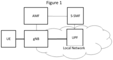
- Figure 1 Some embodiments of inventive concepts are illustrated in Figure 1 . These embodiments are described in the context of the 5G system architecture framework (see, Reference [3] and Reference [4]), but these embodiments may be equally applied to other system architectures as well such as a 4G system (see, Reference [5]).
- the setup of a special type of PDU session (herein referred to as RAN breakout PDU sessions) may be provided with the following properties:
- a RAN breakout PDU session may get special treatment in both the Radio Access Network RAN and the Core Network CN. Accordingly, the RAN breakout PDU session may be differentiated from other PDU sessions.
- the gNB may be split into separate sub-entities, such as a control plane part and a user plane part, which however, may not affect the essence of some embodiments.
- RAN-breakout PDU session may need to be identified and indicated for all concerned entities.
- alternatives that can be considered for RAN-breakout PDU sessions according to some embodiment as follows:
- a determination whether a given session is a RAN breakout PDU session can be made by the AMF using the criteria discussed above. Once the determination is made, the SMF selection can be made accordingly, taking into account whether the session is a RAN breakout session or not. Alternatively, the determination of whether the session is a RAN breakout session can also be made in the SMF, but in that case the SMF selection cannot be dependent on that (or else an SMF re-direction approach may be needed).
- a user plane UP address (or more generally, an ACL) for a UE needs to be set.
- This UP address may be based on an Ethernet MAC (Medium Access Control) address, but in certain cases it may also be based on an IPv4 address or an IPv6 prefix, or may be extended with filters for other header fields as well.
- the ACL is sent to the RAN entity (gNB) when the RAN context is established. At least one user plane address in the ACL may be necessary for each PDU session, but there may be more addresses in certain cases. There are a number of alternatives how the ACL can be set as discussed below:
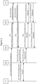
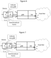
- FIG. 2 is a message diagram illustrating a PDU session establishment procedure. While shown separately from the base station node gNB, the UPF may be considered to be collocated with the base station node gNB. Operations of Figure 2 may apply for non-breakout PDU sessions.
- wireless terminal UE may transmit a session establishment request through base station node gNB to CN entity AMF, and at operation 203, CN entity AMF may transmit a Namf_PDUSession_CreateSMContext message to CN entity SMF.
- CN entity SMF may transmit an N4 Session Establishment Request to UPF entity at operation 203, and UPF entity may reply with an N4 Session Establishment Response at operation 204.
- CN entity SMF may then transmit an Namf_PDUSession_CreateSMResponse to CN entity AMF at operation 205.
- CN entity AMF may transmit an N2 PDU Session Request NAS message to base station node gNB at operation 205, and at operation 207, wireless terminal UE and base station node gNB may perform RRC Reconfiguration and PDU Session Establishment Accept at operation 207.
- Base station node gNB may transmit an N2 PDU Session Request Ack message to CN entity AMF at operation 208, and CN entity AMF may transmit an Nsmf_PDUSession_UpdateSMContext Request message to CN entity SMF at operation 209.
- CN entity SMF may transmit an N4 Session Modification Request to UPF entity.
- UPF entity may transmit an N4 Session Modification Response message to CN entity SMF.
- CN entity SMF may transmit an Nsmf_PDUSession_UpdateSMContext Response.
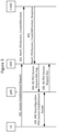
- Figure 3 is a message diagram illustrating a modified procedure for a RAN breakout PDU session.
- the signaling between the CN entity SMF and the UPF entity may be reduced/omitted.
- the N2 tunneling info may not be needed in the AMF-gNB signaling.
- the AMF may not need to contact the SMF after the N2 PDU Session Request Ack is received, since there is no need to update any tunneling info.
- Either the AMF or the SMF may determine that the given session is a RAN breakout PDU session, and the other entities may be informed about this determination.
- signaling may be reduced.
- the SMF may be referred to as S-SMF since its functionality may be reduced.
- the S-SMF may be merged with the AMF.
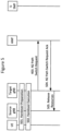
- Figure 4 is a message diagram illustrating a handover signaling procedure for a case involving a central UPF for a non-breakout PDU session.
- a co-located UPF may be insufficient in this case, since in the standard architecture a user plane anchor point may be needed to handle a handover.
- Ethernet MAC learning may be applied to dynamically update the forwarding tables when a UE appears, disappears or its location changes.
- Ethernet forwarding may be applied as follows: In case a switch SW in the local network does not know about the location of a UE with a specific unicast MAC address, the packet can be flooded, where this flooding may be limited to ports that are part of the active topology of the broadcast domain.
- the gNBs should be possible to configure the gNBs such that the flooded packets are not forwarded towards the UEs with a different unicast MAC address to protect the privacy property of the 5G network so that only the addressed UEs receive the packets that are destined to them.
- This should be configurable, as there may be scenarios where frames with unknown unicast MAC address destinations should still be forwarded, such as in the case of moving networks where there may be multiple Ethernet devices behind a single UE.
- the gNB (together with its attached SW) can determine whether the UE with the given MAC address is connected to it by checking the ACL including the user plane address (in this case the MAC address) stored in the UE context. Hence, the gNBs should apply the flooding mechanism with this special condition that flooding may not apply over the air interface depending on configuration.
- a UE When the UE connects to a new gNB, its location within the local network should be updated.
- a UE connects to a new gNB when: attaching (registering) to the network; performing a handover; moving to connected state; or moving to a new gNB while being inactive.
- a broadcast frame/packet for example, all other switches SWs in the local network can learn which direction the given UE is reachable, and hence reduce/avoid the flooding based packet forwarding as mentioned above.
- Such a broadcast packet may, for example, be: in case IPv4 is used, a gratuitous ARP packet; or in case IPv6 is used, an Unsolicited Neighbor Advertisement (RFC 4861) packet.
- the broadcast packet may need to be triggered when the UE appears at a new gNB.
- this trigger can be several variants for this trigger.
- the UE may inform the Ethernet host module within the device through a device-internal Application Programming Interface API that the UE has appeared at a new gNB. This triggers the Ethernet host to send a broadcast packet (frame), where the broadcasting is carried out by the switch SW collocated with the gNB.
- a broadcast trigger is based on UE detection of new gNB according to some embodiments of inventive concepts.
- Three types of traffic may be flooded in an Ethernet network by default: broadcast, unknown unicast, and (unknown) multicast (a.k.a. BUM traffic). Any of such a traffic can be used to update the MAC address table entries of switches.
- An advantage of the broadcast mechanism is that it may be guaranteed to reach all Ethernet hosts in the local network. On the other hand, the broadcast mechanism may cause the Ethernet hosts to parse the frame to determine if further processing is needed.
- An advantage of the unknown unicast mechanism is that it updates the forwarding tables without the need to parse the frame, but it may require the configuration of a unicast address that is not present in the local network.
- a logical gNB may be split into separate control plane and user plane entities in the upper layer, and even if the control plane gNB entity does not change, the user plane gNB entity may be changed. In that case, it may be necessary to broadcast information that identifies the user plane part of the gNB, so that the UE can detect when it has changed. However, sending additional broadcast information may imply increase overhead.
- an explicit indication from the network to the UE may be added when the UE appears at a new gNB.
- This approach is illustrated if Figure 7 where a broadcast trigger is based on an explicit indication of a new gNB in the 5G system.
- the new gNB may indicate to the UE (e.g., using RRC signaling) whether it has moved to a new gNB (or more specifically, whether the user plane part of the gNB is new in case of a split node). This may be done in two ways: either the gNB always indicates an identity of the (user plane part of the) gNB, and the UE detects whether there has been a change; or the RAN only sends the indication in case the user plane part of the gNB has changed (this can be done by keeping the last value of this information in the RAN context of the UE).
- the UE may indicate the change trigger to the Ethernet host in the device, which sends a broadcast frame based on the trigger.
- NAS signaling may be applied for the trigger towards the UE.
- the trigger may be sent from the AMF via the gNB to the UE, based on updated location information from the gNB.
- other protocol options may also be used.
- the switch SW may generate such an Ethernet broadcast on behalf of the UE, based on the information available from the gNB internally within the RAN node.
- the gNB can provide a notification to the SW when a new UE connects to the gNB, and also provide its MAC address as that is part of the ACL stored in the RAN context in the gNB. Based on this notification, the SW generates an Ethernet frame with the given MAC address as the source, and broadcasts it in the local network, thereby updating the forwarding entries. This approach is illustrated in Figure 8 .
- the central controller CTRL approach may require that the location of the UE is also communicated to the central controller, so that the central controller knows which gNB (and associated SW) the UE is attached to. This information may need to be updated each time the UE connects to a new gNB, and each time the UE connection to an old gNB is released.
- the UE can be identified by its user plane address (MAC address or IP address), which is available in the gNB in the context of this solution as part of the ACL.
- frame duplication may be provided at the gNB. It may be possible that a downlink packet (Ethernet frame) that the gNB handles may needs to be forwarded to more than one UE sharing the same broadcast (BC) domain (e.g., using the same VLAN). UEs sharing the same BC domain can have direct L2 communication (e.g., using the same VLAN). Examples for this may include:
- a downlink packet is not delivered to any of the UEs at a given gNB. That may happen if flooding is used to deliver a packet to a UE whose location is currently not known. A flooded packet is not delivered over the air interface unless the ACL of the given UE matches the packet. This is to reduce/avoid privacy concerns over the radio interface.
- Such dynamic IETF methods may include: IPv4 address assignment using DHCPv4; IPv6 address assignment using DHCPv6; or IPv6 stateless address auto-configuration triggered by the UE's router solicitation packet, which is answered by a router in the local network. These methods may need to be triggered by the Host stack above the UE in the device.
- IP address assignment is managed by the 5G system
- possible options include: IPv4 address assignment using NAS signaling during PDU session setup, where the address can be assigned by the S-SMF, possibly taking into account the fact that this is a RAN breakout session.
- the S-SMF may construct an IPv6 Router Advertisement packet on its own, and forward it to the UE via the AMF and the gNB.
- the S-SMF may send the IPv6 router advertisement in the user plane, directly addressed to the UE's MAC address.
- a translation functionality may be applied, where a plain IP packet is mapped to an IP over Ethernet packet at the gNB.
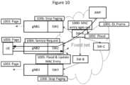
- the gNB If the gNB does not have a connected UE, it initiates the RAN paging for a downlink frame, possibly via other gNBs, or falling back to the AMF triggered paging (if needed), using the appropriate procedures, which take care of delivering the downlink packet to the UE.
- a more general approach may be to support CN idle mode handling. This may also be important as UEs may get to CN idle mode also in error situations. Also, the CN idle mode may be more efficient for UE battery consumption, and may also reduce the RAN resource usage.
- the approach for handling paging in CN idle mode may be based on triggering and stopping the paging process locally at a gNB by a user plane packet.
- the MAC forwarding entry in the local network ages out for a UE in idle mode. This can be achieved via several methods (e.g., by tuning the MAC address aging parameter).
- MAC aging may be configured in such a way that by the time the UE becomes idle in the 5G system, the MAC address entry is removed in the local network.
- the timeout for MAC aging may be set to a value that is not greater than the connected to idle timeout configured in RAN.
- An alternative option may be to use signaling between 5G and the Ethernet domain to trigger the UE specific MAC aging (i.e., purge the MAC address of the UE) in the Ethernet domain if the UE goes idle.
- Operation 1002 As the MAC forwarding entry corresponding to the UE has been aged out, the frame is flooded in the local network using the Ethernet flooding mechanism. Hence, the downlink frame reaches gNB1, gNB2 and gNB3.
- the UE sends a local Ethernet frame when it becomes connected at gNB2.
- a local Ethernet frame could be, for example, a gratuitous ARP packet in case IPv4 is used sent as a broadcast frame; an Unsolicited Neighbor Advertisements (RFC 4861) packet in case IPv6 is used sent as a multicast frame; or any other Ethernet frame with the MAC UE's address as the source, which could be, for example, a unicast frame towards a not known destination address in the local network.
- the gNB may construct such an Ethernet frame on behalf of the UE and send it, in which case the UE does not need extra functionality for this and the frame is sent by the gNB.
- the gNB may know the MAC address used by the UE from the RAN context, based on a priori signaling, as discussed above with respect to setting a user plane address.
- the MAC aging timeout in the fixed part of the network should be not greater than the RAN connected to idle timeout. If the MAC aging timeout is smaller, this may lead to unnecessary flooding in the fixed network and unnecessary paging in RAN, yet the system can deliver the downlink frame. If the MAC aging timeout is bigger than the RAN connected to idle timeout, then the downlink frame will be delivered only if the UE has not moved to another gNB, since the paging will be triggered only at the gNB where the UE last had traffic to send.
- a downlink packet may arrive at a gNB which might not be the same gNB where the UE camps on in idle mode, hence it may be needed to trigger paging in the other gNBs of the local network as well.
- a local network may be limited in size, and therefore, it may be possible that paging takes place at all gNBs of the local network if needed. Stated in other words, the local network is not further divided into TAs (Tracking Areas) so that the UE would only be paged in its current TA.
- TAs Tracking Areas
- paging can be triggered by flooding the downlink user plane frame to other gNBs of the local network. This is possible by making use of the flooding mechanism present in a local Ethernet network, using the Ethernet mechanisms to enforce an active topology (e.g., RSTP - Rapid Spanning Tree Protocol).
- the flooded frames will trigger paging at the gNBs if the UE is not connected. Note that this may require appropriate configuration in the gNBs so that frames with unknown destination trigger paging rather than being dropped.
- the UE In rare cases, it may happen that the UE is connected at a gNB that gets a flooded downlink frame, despite the fact that the downlink frame triggered a paging at another gNB. This may not be a normal case, because as soon as a UE gets connected to a new gNB, a to be flooded frame is sent with the UE's source address, which updates the forwarding rules in the local network so that the frames destined to the given UE will be forwarded to the gNB where the UE is connected. However, in rare cases this frame might get lost, or there may be transient events in the network that prevent the forwarding rules from being properly updated.
- One advantage of this approach may be that it reduces/minimizes the amount of flooding in the local network and instead it only relies on a multicast paging triggering.
- One issue may be that in case the UE happens to be connected at another gNB in some rare cases (as discussed above), it may become an issue how to deliver the downlink frame to the UE, since in that case a broadcast with the UE's address as the source would not automatically be sent.
- One solution could be that in such a case the gNB where the UE is connected would send such a frame on the UE's behalf.
- the system may need a number of parameters. These parameters may include:
- the AMF could retrieve the equipment identity from the UE when it connects to the AMF using a procedure corresponding to the Identity Request procedure that exist for EPS as discussed in 3GPP TS 24.301 v15.1.1, 2018-01, Non-Access-Stratum (NAS) protocol for Evolved Packet System (EPS), Stage 3, Release 15 (also referred to as Reference [7]).
- NAS Non-Access-Stratum
- EPS Evolved Packet System
- Stage 3 Release 15 also referred to as Reference [7]
- the latter may require that the information element "Identity Type 2" is extended to cover also equipment identities including the MAC address. Note that the procedure and parameter names for 5GS would probably be different.
- the parameters can be cached in the gNBs, but after a certain time the cached information may be released, in which case it can be retrieved from a central database.
- This approach may stop paging at other gNBs even before the actual paging starts. But it may also be possible that the paging is delayed for a short period of time so that paging can be stopped before it even begins.
- This option may be applied only in special conditions: e.g., only when the management system configures it, based on an excessive number of paging attempts; or one gNB may trigger the use of this option based on the excessive number of paging attempts and notify other gNBs to also use this option.
- the UE leaves the local network but still gets served by the macro network coverage. This may be the case when the local network is being operated in cooperation with a wide area network operator, or by the very same wide area network operator itself.
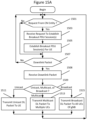
- the session establishment request of block 1401 and the request of block 1405 may further include a user plane address for the wireless terminal UE. Furthermore, the session establishment request of block 1401 may include an indication to request the breakout PDU session, and at block 1403, determining that the PDU session is to be established may include determining that the PDU session should be established based on the indication from the session establishment request. Moreover, determining that the PDU session is to be established at block 1403 may include determining that the PDU session is to be established based on at least one of an identity of the wireless terminal UE and/or an identity of the base station node gNB.
- the breakout PDU session may be at least one of an Ethernet breakout PDU session and/or an internet protocol IP breakout PDU session, and/or the session establishment request may be provided as a non-access stratum NAS message.
- processor 1203 may receive the request through network interface 1207 from a core network CN entity (e.g., AMF node/server) at block 1503, for example, as discussed above with respect to operation 304 of Figure 3 .
- the request may include an indication that a breakout PDU session is to be established for a wireless terminal UE and a user plane address for the breakout PDU session for the wireless terminal UE.
- processor 1203 may establish the breakout PDU session for the wireless terminal UE, for example, as discussed above with respect to operation 305 and/or operation 306 of Figure 3 .
- processor 1203 may receive the downlink packet through network interface 1207 from a local area network at block 1508, and the downlink packet may include the user plane address.
- processor 1203 may transmit (1511) the downlink packet over a radio interface to the wireless terminal UE in accordance with the breakout PDU session at block 1511.
- the user plane address for the wireless terminal UE may be based on at least one of a medium access control MAC address for the wireless terminal UE and/or an internet protocol IP address for the wireless terminal UE.
- the breakout PDU session may be an Ethernet breakout PDU session, and the user plane address for the wireless terminal UE may be a medium access control MAC address for the wireless terminal.
- the breakout PDU session may be an internet protocol IP breakout PDU session, and the user plane address for the wireless terminal UE may be an IP address for the wireless terminal.
- first and second breakout PDU sessions may be established for the wireless terminal UE to provide two paths for duplicate transmission of the same downlink packet.
- processor 1203 may thus establish first and second breakout PDU sessions for the wireless terminal UE responsive to the request, wherein the same user plane address is used for both of the first and second breakout PDU sessions.
- transmitting the downlink packet at block 1511 may include duplicating the downlink packet and transmitting the downlink packet to the wireless terminal in accordance with the first breakout PDU session and in accordance with the second breakout PDU session responsive to the user plane address of the downlink packet matching the user plane address for the wireless terminal (UE).
- the same downlink packet may thus be received by wireless terminal UE twice (via the first and second breakout PDU sessions), for example, to improve reliability by redundancy.
- the user plane address for the wireless terminal UE may be included in an Access Control List ACL saved in memory 1205.
- the ACL for the UE may include the user plane address that is for unicast downlink transmissions to the UE, and the ACL for the UE may also include a multicast address that is used for multicast transmissions to a plurality of UEs. No address may be needed in the ACL for broadcast downlink transmissions, because the base station node gNB transmits broadcast downlink transmissions to all UEs connected with the base station node gNB.
- multicast and/or broadcast downlink transmissions may be supported to allow transmission of the same downlink packet to multiple wireless terminals.
- the same multicast address may be stored in ACLs in memory 1205 for multiple wireless terminals.
- processor 1203 may receive a request from the CN entity (through network interface 1207) including an indication that a second breakout PDU session is to be established for a second wireless terminal, and at block 1505, processor 1203 may establish the second breakout PDU session for the second wireless terminal.
- a multicast address may also be provided for the first and second wireless terminals and the multicast address may be saved in the respective ACLs for the first and second wireless terminals.
- a second downlink packet may be received over the local area network (through network interface 1207) at processor 1203, and the second downlink packet may include the multicast address. Responsive to the second downlink packet including the multicast address at block 1509, processor 1203 may transmit the second downlink packet to the first and second wireless terminals using the first and second breakout PDU sessions responsive to the multicast address of the downlink packet matching the multicast address of the respective ACLs for the first and second wireless terminals.
- a third downlink packet may be received at processor 1203, and the third downlink packet may include a broadcast address. Responsive to the third downlink packet including the broadcast address at block 1509, processor 1203 may transmit the third downlink packet to all wireless terminals (including the first and second wireless terminals) in connection with the base station.
- Figure 15C illustrates base station node gNB operations when an update packet is received from the wireless terminal UE.
- processor 1203 Responsive to receiving an update packet from the wireless terminal UE over the radio interface (through transceiver 1201) at block 1531, processor 1203 may initiate transmission of the update packet through network interface 1207 to a plurality of nodes of the local area network at block 1533, and the update packet may include the user plane address for the wireless terminal. Transmission of such update packets is discussed above, for example, with respect to Figures 6 and 7 .
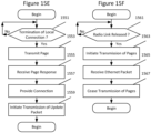
- Figure 15E illustrates base station node gNB operations when a local connection with the wireless terminal is terminated.
- a first downlink packet may be transmitted to the wireless terminal at block 1511.
- processor 1203 may receive a second downlink packet through network interface 1207 at block 1508, with the second downlink packet including the user plane address for the wireless terminal UE as discussed above with respect to Operation 1002 of Figure 10 .
- processor 1203 may transmit a page through transceiver 1201 over the radio interface to the wireless terminal UE at block 1553 as discussed above with respect to operation 1003 of Figure 10 .
- Processor 1203 may receive a page response from the wireless terminal UE through transceiver 1201 at block 1555, with the page response being responsive to the page, as discussed above with respect to Operation 1004 of Figure 10 .
- processor 1201 may provide connection with the wireless terminal UE responsive to the page response, and providing the connection may include providing a context for the wireless terminal including the user plane address for the wireless terminal in memory 1205 as discussed above with respect to Operation 1004 of Figure 10 .
- initiating transmission of the update packet at block 1559 may include initiating transmission of the update packet responsive to providing the connection with the wireless terminal UE. According to some other embodiments, initiating transmission of the update packet at block 1559 may include initiating transmission of the update packet responsive to receiving the update packet from the wireless terminal (UE) over the radio interface.
- Figure 15F illustrates base station node gNB operations when a radio link is released.
- processor 1203 may release a radio link for the wireless terminal at block 1561.
- processor 1203 may receive a second downlink packet including the user plane address for the breakout PDU session for the wireless terminal UE at block 1508. Responsive to receiving the second downlink packet after releasing the radio link, processor 1203 may initiate transmission of pages through transceiver 1207 over the radio interface for the wireless terminal UE at block 1563.
- processor 1203 may receive an Ethernet packet including the user plane address from a second base station node of the wireless communication network through network interface 1207 at block 1565. Responsive to receiving the Ethernet packet including the user plane address, processor 1203 may cease transmission of the pages for the wireless terminal at block 1567.
- processor 1103 may transmit a session establishment request through transceiver 1101 over the radio interface through the base station node gNB to a core network CN entity AMF, and the session establishment request may include a user plane address for the wireless terminal UE.
- processor 1103 may transmit an update packet through transceiver 1101 over a radio interface to a base station node gNB of a wireless communication network, and the update packet may include the user plane address for the wireless terminal UE.
- processor 1101 may receive a downlink packet over the radio interface from the base station node gNB through transceiver 1101, and the downlink packet may include the user plane address.
- the update packet may include at least one of an ARP packet, an Unsolicited Neighbor Advertisement packet, and/or an Ethernet frame. Transmitting the update packet may include transmitting the update packet responsive to detecting movement of the wireless terminal UE to the base station node gNB from another base station node. Transmitting the update packet may include transmitting the update packet responsive to receiving an indication over the radio interface from the base station node gNB.
- the wireless terminal may be implemented using the structure of Figure 11 with modules stored in memory 1105 so that the modules provide instructions so that when the instructions of a module are executed by processor 1103, processor 1103 performs respective operations.
- Processor 1103 of wireless terminal UE may thus transmit and/or receive communications to/from one or more base station nodes or other nodes/entities of a wireless communication network through transceiver 1101.
- processor 1103 may transmit an update packet through transceiver 1101 over a radio interface to the second base station node gNB2 responsive to connecting with the second base station node gNB2, and the update packet may include a user plane address for the wireless terminal UE.
- processor 1103 may receive a downlink packet through transceiver 1101 over the radio interface from the second base station node gNB2, and the downlink packet may include the user plane address.
- FIG. 16A may be optional with respect to some embodiments. For example, operations of blocks 1651, 1653, 1655, and 1657 may be optional.
- central controller CTRL Operations of a central controller CTRL will now be discussed with reference to the flow chart of Figure 17 according to some embodiments of inventive concepts where the central controller CTRL is couples with a plurality of nodes of a local area network.
- the central controller CTRL may be implemented using the structure of Figure 13 with modules stored in memory 1305 so that the modules provide instructions so that when the instructions of a module are executed by processor 1303, processor 1303 performs respective operations.
- Processor 1303 of wireless terminal UE may thus transmit and/or receive communications to/from one or more base station nodes or other nodes/entities of a wireless communication network through network interface 1307.
- the user plane address for the wireless terminal UE may be based on at least one of a medium access control MAC address for the wireless terminal UE and/or an internet protocol IP address for the wireless terminal UE.
- the user plane address for the wireless terminal may be a medium access control MAC address, and the address tables of the plurality of nodes may be MAC forwarding tables.
- the user plane address for the wireless terminal may be an internet protocol IP address, and the address tables of the plurality of nodes may be IP routing tables.
- a communication system includes telecommunication network QQ410, such as a 3GPP-type cellular network, which comprises access network QQ411, such as a radio access network, and core network QQ414.
- Access network QQ411 comprises a plurality of base stations QQ412a, QQ412b, QQ412c, such as NBs, eNBs, gNBs or other types of wireless access points, each defining a corresponding coverage area QQ413a, QQ413b, QQ413c.
- Each base station QQ412a, QQ412b, QQ412c is connectable to core network QQ414 over a wired or wireless connection QQ415.
- a first UE QQ491 located in coverage area QQ413c is configured to wirelessly connect to, or be paged by, the corresponding base station QQ412c.
- a second UE QQ492 in coverage area QQ413a is wirelessly connectable to the corresponding base station QQ412a. While a plurality of UEs QQ491, QQ492 are illustrated in this example, the disclosed embodiments are equally applicable to a situation where a sole UE is in the coverage area or where a sole UE is connecting to the corresponding base station QQ412.
- Telecommunication network QQ410 is itself connected to host computer QQ430, which may be embodied in the hardware and/or software of a standalone server, a cloud-implemented server, a distributed server or as processing resources in a server farm.
- Host computer QQ430 may be under the ownership or control of a service provider, or may be operated by the service provider or on behalf of the service provider.
- Connections QQ421 and QQ422 between telecommunication network QQ410 and host computer QQ430 may extend directly from core network QQ414 to host computer QQ430 or may go via an optional intermediate network QQ420.
- Intermediate network QQ420 may be one of, or a combination of more than one of, a public, private or hosted network; intermediate network QQ420, if any, may be a backbone network or the Internet; in particular, intermediate network QQ420 may comprise two or more sub-networks (not shown).
- the communication system of Figure 18 as a whole enables connectivity between the connected UEs QQ491, QQ492 and host computer QQ430.
- the connectivity may be described as an over-the-top (OTT) connection QQ450.
- Host computer QQ430 and the connected UEs QQ491, QQ492 are configured to communicate data and/or signaling via OTT connection QQ450, using access network QQ411, core network QQ414, any intermediate network QQ420 and possible further infrastructure (not shown) as intermediaries.
- OTT connection QQ450 may be transparent in the sense that the participating communication devices through which OTT connection QQ450 passes are unaware of routing of uplink and downlink communications.
- base station QQ412 may not or need not be informed about the past routing of an incoming downlink communication with data originating from host computer QQ430 to be forwarded (e.g., handed over) to a connected UE QQ491.
- base station QQ412 need not be aware of the future routing of an outgoing uplink communication originating from the UE QQ491 towards the host computer QQ430.
- host computer QQ510 comprises hardware QQ515 including communication interface QQ516 configured to set up and maintain a wired or wireless connection with an interface of a different communication device of communication system QQ500.
- Host computer QQ510 further comprises processing circuitry QQ518, which may have storage and/or processing capabilities.
- processing circuitry QQ518 may comprise one or more programmable processors, application-specific integrated circuits, field programmable gate arrays or combinations of these (not shown) adapted to execute instructions.
- Communication system QQ500 further includes base station QQ520 provided in a telecommunication system and comprising hardware QQ525 enabling it to communicate with host computer QQ510 and with UE QQ530.
- Hardware QQ525 may include communication interface QQ526 for setting up and maintaining a wired or wireless connection with an interface of a different communication device of communication system QQ500, as well as radio interface QQ527 for setting up and maintaining at least wireless connection QQ570 with UE QQ530 located in a coverage area (not shown in Figure 19 ) served by base station QQ520.
- Communication interface QQ526 may be configured to facilitate connection QQ560 to host computer QQ510.
- Connection QQ560 may be direct or it may pass through a core network (not shown in Figure 19 ) of the telecommunication system and/or through one or more intermediate networks outside the telecommunication system.
- hardware QQ525 of base station QQ520 further includes processing circuitry QQ528, which may comprise one or more programmable processors, application-specific integrated circuits, field programmable gate arrays or combinations of these (not shown) adapted to execute instructions.
- Base station QQ520 further has software QQ521 stored internally or accessible via an external connection.
- Communication system QQ500 further includes UE QQ530 already referred to.
- Its hardware QQ535 may include radio interface QQ537 configured to set up and maintain wireless connection QQ570 with a base station serving a coverage area in which UE QQ530 is currently located.
- Hardware QQ535 of UE QQ530 further includes processing circuitry QQ538, which may comprise one or more programmable processors, application-specific integrated circuits, field programmable gate arrays or combinations of these (not shown) adapted to execute instructions.
- UE QQ530 further comprises software QQ531, which is stored in or accessible by UE QQ530 and executable by processing circuitry QQ538.
- Software QQ531 includes client application QQ532.
- Client application QQ532 may be operable to provide a service to a human or non-human user via UE QQ530, with the support of host computer QQ510.
- an executing host application QQ512 may communicate with the executing client application QQ532 via OTT connection QQ550 terminating at UE QQ530 and host computer QQ510.
- client application QQ532 may receive request data from host application QQ512 and provide user data in response to the request data.
- OTT connection QQ550 may transfer both the request data and the user data.
- Client application QQ532 may interact with the user to generate the user data that it provides.
- host computer QQ510, base station QQ520 and UE QQ530 illustrated in Figure 19 may be similar or identical to host computer QQ430, one of base stations QQ412a, QQ412b, QQ412c and one of UEs QQ491, QQ492 of Figure 18 , respectively.
- the inner workings of these entities may be as shown in Figure 19 and independently, the surrounding network topology may be that of Figure 18 .
- OTT connection QQ550 has been drawn abstractly to illustrate the communication between host computer QQ510 and UE QQ530 via base station QQ520, without explicit reference to any intermediary devices and the precise routing of messages via these devices.
- Network infrastructure may determine the routing, which it may be configured to hide from UE QQ530 or from the service provider operating host computer QQ510, or both. While OTT connection QQ550 is active, the network infrastructure may further take decisions by which it dynamically changes the routing (e.g., on the basis of load balancing consideration or reconfiguration of the network).
- Wireless connection QQ570 between UE QQ530 and base station QQ520 is in accordance with the teachings of the embodiments described throughout this disclosure.
- One or more of the various embodiments improve the performance of OTT services provided to UE QQ530 using OTT connection QQ550, in which wireless connection QQ570 forms the last segment. More precisely, the teachings of these embodiments may provide redundancy for uplink/downlink communications through the wireless communication network and thereby provide benefits such as improved reliability.
- a measurement procedure may be provided for the purpose of monitoring data rate, latency and other factors on which the one or more embodiments improve.
- the measurement procedure and/or the network functionality for reconfiguring OTT connection QQ550 may be implemented in software QQ511 and hardware QQ515 of host computer QQ510 or in software QQ531 and hardware QQ535 of UE QQ530, or both.
- sensors may be deployed in or in association with communication devices through which OTT connection QQ550 passes; the sensors may participate in the measurement procedure by supplying values of the monitored quantities exemplified above, or supplying values of other physical quantities from which software QQ511, QQ531 may compute or estimate the monitored quantities.
- the reconfiguring of OTT connection QQ550 may include message format, retransmission settings, preferred routing etc.; the reconfiguring need not affect base station QQ520, and it may be unknown or imperceptible to base station QQ520. Such procedures and functionalities may be known and practiced in the art.
- measurements may involve proprietary UE signaling facilitating host computer QQ510's measurements of throughput, propagation times, latency and the like. The measurements may be implemented in that software QQ511 and QQ531 causes messages to be transmitted, in particular empty or 'dummy' messages, using OTT connection QQ550 while it monitors propagation times, errors etc.
- FIG 20 is a flowchart illustrating a method implemented in a communication system, in accordance with one embodiment.
- the communication system includes a host computer, a base station and a UE which may be those described with reference to Figures 18 and 19 .
- the host computer provides user data.
- substep QQ611 (which may be optional) of step QQ610, the host computer provides the user data by executing a host application.
- step QQ620 the host computer initiates a transmission carrying the user data to the UE.
- step QQ630 the base station transmits to the UE the user data which was carried in the transmission that the host computer initiated, in accordance with the teachings of the embodiments described throughout this disclosure.
- step QQ640 the UE executes a client application associated with the host application executed by the host computer.
- FIG 21 is a flowchart illustrating a method implemented in a communication system, in accordance with one embodiment.
- the communication system includes a host computer, a base station and a UE which may be those described with reference to Figures 18 and 19 .
- the host computer provides user data.
- the host computer provides the user data by executing a host application.
- the host computer initiates a transmission carrying the user data to the UE.
- the transmission may pass via the base station, in accordance with the teachings of the embodiments described throughout this disclosure.
- step QQ730 (which may be optional), the UE receives the user data carried in the transmission.
- FIG 22 is a flowchart illustrating a method implemented in a communication system, in accordance with one embodiment.
- the communication system includes a host computer, a base station and a UE which may be those described with reference to Figures 18 and 19 .
- the UE receives input data provided by the host computer.
- the UE provides user data.
- substep QQ821 (which may be optional) of step QQ820, the UE provides the user data by executing a client application.
- substep QQ811 (which may be optional) of step QQ810, the UE executes a client application which provides the user data in reaction to the received input data provided by the host computer. In providing the user data, the executed client application may further consider user input received from the user. Regardless of the specific manner in which the user data was provided, the UE initiates, in substep QQ830 (which may be optional), transmission of the user data to the host computer. In step QQ840 of the method, the host computer receives the user data transmitted from the UE, in accordance with the teachings of the embodiments described throughout this disclosure.
- FIG 23 is a flowchart illustrating a method implemented in a communication system, in accordance with one embodiment.
- the communication system includes a host computer, a base station and a UE which may be those described with reference to Figures 18 and 19 .
- the base station receives user data from the UE.
- the base station initiates transmission of the received user data to the host computer.
- the host computer receives the user data carried in the transmission initiated by the base station.
- any appropriate steps, methods, features, functions, or benefits disclosed herein may be performed through one or more functional units or modules of one or more virtual apparatuses.
- Each virtual apparatus may comprise a number of these functional units.
- These functional units may be implemented via processing circuitry, which may include one or more microprocessor or microcontrollers, as well as other digital hardware, which may include digital signal processors (DSPs), special-purpose digital logic, and the like.
- the processing circuitry may be configured to execute program code stored in memory, which may include one or several types of memory such as read-only memory (ROM), random-access memory (RAM), cache memory, flash memory devices, optical storage devices, etc.
- Program code stored in memory includes program instructions for executing one or more telecommunications and/or data communications protocols as well as instructions for carrying out one or more of the techniques described herein.
- the processing circuitry may be used to cause the respective functional unit to perform corresponding functions according one or more embodiments of the present disclosure.
- the terms “comprise”, “comprising”, “comprises”, “include”, “including”, “includes”, “have”, “has”, “having”, or variants thereof are open-ended, and include one or more stated features, integers, elements, steps, components or functions but does not preclude the presence or addition of one or more other features, integers, elements, steps, components, functions or groups thereof.
- the common abbreviation “e.g.”, which derives from the Latin phrase “exempli gratia” may be used to introduce or specify a general example or examples of a previously mentioned item, and is not intended to be limiting of such item.
- the common abbreviation “i.e.”, which derives from the Latin phrase “id est,” may be used to specify a particular item from a more general recitation.
- Example embodiments are described herein with reference to block diagrams and/or flowchart illustrations of computer-implemented methods, apparatus (systems and/or devices) and/or computer program products. It is understood that a block of the block diagrams and/or flowchart illustrations, and combinations of blocks in the block diagrams and/or flowchart illustrations, can be implemented by computer program instructions that are performed by one or more computer circuits.
- These computer program instructions may be provided to a processor circuit of a general purpose computer circuit, special purpose computer circuit, and/or other programmable data processing circuit to produce a machine, such that the instructions, which execute via the processor of the computer and/or other programmable data processing apparatus, transform and control transistors, values stored in memory locations, and other hardware components within such circuitry to implement the functions/acts specified in the block diagrams and/or flowchart block or blocks, and thereby create means (functionality) and/or structure for implementing the functions/acts specified in the block diagrams and/or flowchart block(s).
Landscapes
- Engineering & Computer Science (AREA)
- Computer Networks & Wireless Communication (AREA)
- Signal Processing (AREA)
- Databases & Information Systems (AREA)
- Mobile Radio Communication Systems (AREA)
Claims (14)
- Verfahren zum Betreiben einer Entität (AMF) eines Kernnetzwerks, CN, eines Drahtloskommunikationsnetzwerks, wobei das Verfahren Folgendes umfasst:Empfangen (1401) einer Sitzungsaufbauanforderung von einem drahtlosen Endgerät (UE) über einen Basisstationsknoten (gNB);in Reaktion auf das Empfangen der Sitzungsaufbauanforderung Bestimmen (1403), dass eine Breakout-Protokolldateneinheitssitzung, Breakout-PDU-Sitzung, für das drahtlose Endgerät (UE) aufgebaut werden soll, basierend auf mindestens einer von einer Identität des drahtlosen Endgeräts (UE) und/oder einer Identität des Basisstationsknotens (gNB);in Reaktion auf das Bestimmen, dass die Breakout-PDU-Sitzung für das drahtlose Endgerät (UE) aufgebaut werden soll, Senden (1405) einer Anforderung an den Basisstationsknoten (gNB), wobei die Anforderung eine Angabe umfasst, dass die Breakout-PDU-Sitzung für das drahtlose Endgerät (UE) mit einem lokalen Netzwerk aufgebaut werden soll, das eine Benutzerebenen-Schnittstelle zu dem Basisstationsknoten (gNB) aufweist; undBereitstellen einer Benutzerebenen-Adresse des drahtlosen Endgeräts (UE), die für Unicast-Downlink-Übertragungen an das drahtlose Endgerät (UE) verwendet wird, und/oder einer Multicast-Adresse, die für Multicast-Übertragungen an eine Mehrzahl von drahtlosen Endgeräten verwendet wird, für den Basisstationsknoten (gNB).
- Verfahren nach Anspruch 1, wobei die Sitzungsaufbauanforderung eine Angabe zum Anfordern der Breakout-PDU-Sitzung umfasst und wobei das Bestimmen, dass die PDU-Sitzung aufgebaut werden soll, ein Bestimmen umfasst, dass die PDU-Sitzung basierend auf der Angabe aus der Sitzungsaufbauanforderung aufgebaut werden sollte.
- Verfahren nach einem der Ansprüche 1 bis 2, ferner umfassend:
Initiieren (1407) einer Übertragung einer Benachrichtigung an eine zentrale Steuerung (CTRL), wobei die Benachrichtigung die Benutzerebenen-Adresse des drahtlosen Endgeräts (UE) und eine Identität des Basisstationsknotens (gNB) umfasst. - Verfahren zum Betreiben eines Drahtloskommunikationsnetzwerks, wobei das Verfahren Folgendes umfasst:Empfangen (1401) einer Sitzungsaufbauanforderung von einem drahtlosen Endgerät (UE) durch eine Entität (AMF) eines Kernnetzwerks, CN, des Drahtloskommunikationsnetzwerks über einen Basisstationsknoten (gNB);in Reaktion auf das Empfangen der Sitzungsaufbauanforderung Bestimmen (1403), dass eine Breakout-Protokolldateneinheitssitzung, Breakout-PDU-Sitzung, für das drahtlose Endgerät (UE) aufgebaut werden soll, durch die CN-Entität basierend auf mindestens einer von einer Identität des drahtlosen Endgeräts (UE) und/oder einer Identität des Basisstationsknotens (gNB);in Reaktion auf das Bestimmen, dass die Breakout-PDU-Sitzung für das drahtlose Endgerät (UE) aufgebaut werden soll, Senden (1405) einer Anforderung durch die CN-Entität an den Basisstationsknoten (gNB), wobei die Anforderung eine Angabe umfasst, dass die Breakout-PDU-Sitzung für das drahtlose Endgerät (UE) mit einem lokalen Netzwerk aufgebaut werden soll, das eine Benutzerebenen-Schnittstelle zu dem Basisstationsknoten (gNB) aufweist;Bereitstellen einer Benutzerebenen-Adresse des drahtlosen Endgeräts (UE), die für Unicast-Downlink-Übertragungen an das drahtlose Endgerät (UE) verwendet wird, und/oder einer Multicast-Adresse, die für Multicast-Übertragungen an eine Mehrzahl von drahtlosen Endgeräten verwendet wird, durch die CN-Entität für den Basisstationsknoten (gNB);Aufbauen der Breakout-PDU-Sitzung durch den Basisstationsknoten in Reaktion auf die von der CN-Entität gesendete Anforderung;Empfangen (1508) eines Downlink-Pakets an dem Basisstationsknoten (gNB) über das lokale Netzwerk, wobei das Downlink-Paket eine Benutzerebenen-Adresse umfasst; undin Reaktion darauf, dass die Benutzerebenen-Adresse des Downlink-Pakets mit der Benutzerebenen-Adresse für die Breakout-PDU-Sitzung für das drahtlose Endgerät (UE) oder der Multicast-Adresse übereinstimmt, Senden (1511) des Downlink-Pakets durch den Basisstationsknoten über eine Funkschnittstelle gemäß der Breakout-PDU-Sitzung an das drahtlose Endgerät (UE).
- Verfahren nach Anspruch 4, ferner umfassend durch den Basisstationsknoten:
in Reaktion auf ein Erkennen von Bewegung des drahtlosen Endgeräts (UE) von einem anderen Basisstationsknoten zu dem Basisstationsknoten (gNB) Initiieren einer Übertragung (1523) eines Aktualisierungspakets an eine Mehrzahl von Knoten des lokalen Netzwerks, wobei das Aktualisierungspaket die Benutzerebenen-Adresse für das drahtlose Endgerät umfasst. - Verfahren nach Anspruch 5, ferner umfassend:
in Reaktion auf ein Empfangen eines Aktualisierungspakets von dem drahtlosen Endgerät (UE) über die Funkschnittstelle Initiieren einer Übertragung (1533) eines Aktualisierungspakets an eine Mehrzahl von Knoten des lokalen Netzwerks, wobei das Aktualisierungspaket die Benutzerebenen-Adresse für das drahtlose Endgerät umfasst. - Verfahren nach einem der Ansprüche 1 bis 6, wobei die Benutzerebenen-Adresse für das drahtlose Endgerät (UE) auf mindestens einer von einer Medienzugriffssteuerungsadresse, MAC-Adresse, für das drahtlose Endgerät (UE) und/oder einer Internetprotokolladresse, IP-Adresse, für das drahtlose Endgerät (UE) basiert.
- Verfahren nach einem der Ansprüche 1 bis 7, wobei die Breakout-PDU-Sitzung eine Ethernet-Breakout-PDU-Sitzung ist und wobei die Benutzerebenen-Adresse für das drahtlose Endgerät (UE) eine Medienzugriffssteuerungsadresse, MAC-Adresse, für das drahtlose Endgerät ist.
- Verfahren nach einem der Ansprüche 1 bis 8, wobei die Breakout-PDU-Sitzung eine Internetprotokoll-Breakout-PDU-Sitzung, IP-Breakout-PDU-Sitzung, ist und wobei die Benutzerebenen-Adresse für das drahtlose Endgerät (UE) eine IP-Adresse für das drahtlose Endgerät ist.
- Verfahren nach einem der Ansprüche 1 bis 9, wobei die Benutzerebenen-Adresse für das drahtlose Endgerät (UE) und/oder die Multicast-Adresse in einer Zugriffsteuerungsliste, ACL, umfasst sind.
- Entität (AMF) eines Kernnetzwerks, CN, die ausgelegt ist zum:Empfangen einer Sitzungsaufbauanforderung von einem drahtlosen Endgerät (UE) über einen Basisstationsknoten (gNB);Bestimmen, dass eine Breakout-Protokolldateneinheitssitzung, Breakout-PDU-Sitzung, für das drahtlose Endgerät (UE) aufgebaut werden soll, in Reaktion auf das Empfangen der Sitzungsaufbauanforderung basierend auf mindestens einer von einer Identität des drahtlosen Endgeräts (UE) und/oder einer Identität des Basisstationsknotens (gNB);Senden einer Anforderung an den Basisstationsknoten (gNB) in Reaktion auf das Bestimmen, dass die Breakout-PDU-Sitzung für das drahtlose Endgerät (UE) aufgebaut werden soll, wobei die Anforderung eine Angabe umfasst, dass die Breakout-PDU-Sitzung mit einem lokalen Netzwerk aufgebaut werden soll, das eine Benutzerebenen-Schnittstelle zu dem Basisstationsknoten (gNB) für das drahtlose Endgerät (UE) aufweist; undBereitstellen einer Benutzerebenen-Adresse des drahtlosen Endgeräts (UE), die für Unicast-Downlink-Übertragungen an das drahtlose Endgerät (UE) verwendet wird, und/oder einer Multicast-Adresse, die für Multicast-Übertragungen an eine Mehrzahl von drahtlosen Endgeräten verwendet wird, für den Basisstationsknoten.
- CN-Entität nach Anspruch 11, die zum Durchführen des Verfahrens nach einem der Ansprüche 2 bis 3 ausgelegt ist.
- Drahtloskommunikationsnetzwerk, umfassend- eine Entität (AMF) eines Kernnetzwerks, CN, nach Anspruch 11 oder 12,- einen Basisstationsknoten (gNB), der ausgelegt ist zum:Empfangen einer Anforderung von der CN-Entität (AMF) eines Drahtloskommunikationsnetzwerk, wobei die Anforderung eine Angabe umfasst, dass eine Breakout-PDU-Sitzung für ein drahtloses Endgerät (UE) mit einem lokalen Netzwerk aufgebaut werden soll, das eine Benutzerebenen-Schnittstelle zu dem Basisstationsknoten (gNB) aufweist;Empfangen einer Benutzerebenen-Adresse des drahtlosen Endgeräts (UE), die für Unicast-Downlink-Übertragungen an das drahtlose Endgerät (UE) für die Breakout-PDU-Sitzung für das drahtlose Endgerät (UE) verwendet wird, und/oder einer Multicast-Adresse, die für Multicast-Übertragungen an eine Mehrzahl von drahtlosen Endgeräten verwendet wird, von der CN-Entität (AMF) ;Aufbauen der Breakout-PDU-Sitzung in Reaktion auf die Anforderung;Empfangen eines Downlink-Pakets an dem Basisstationsknoten (gNB) über ein lokales Netzwerk, wobei das Downlink-Paket eine Benutzerebenen-Adresse umfasst; undSenden des Downlink-Pakets über eine Funkschnittstelle an das drahtlose Endgerät (UE) gemäß der Breakout-PDU-Sitzung in Reaktion darauf, dass die Benutzerebenen-Adresse des Downlink-Pakets mit der Benutzerebenen-Adresse für die Breakout-PDU-Sitzung für das drahtlose Endgerät (UE) oder der Multicast-Adresse übereinstimmt.
- Drahtloskommunikationsnetzwerk nach Anspruch 13, ausgelegt zum Durchführen des Verfahrens nach einem der Ansprüche 5 bis 10.
Applications Claiming Priority (1)
| Application Number | Priority Date | Filing Date | Title |
|---|---|---|---|
| PCT/IB2018/050944 WO2019158973A1 (en) | 2018-02-15 | 2018-02-15 | Method for providing a breakout pdu session for local ip access |
Publications (2)
| Publication Number | Publication Date |
|---|---|
| EP3753271A1 EP3753271A1 (de) | 2020-12-23 |
| EP3753271B1 true EP3753271B1 (de) | 2025-04-09 |
Family
ID=61563439
Family Applications (1)
| Application Number | Title | Priority Date | Filing Date |
|---|---|---|---|
| EP18708751.5A Active EP3753271B1 (de) | 2018-02-15 | 2018-02-15 | Verfahren zur bereitstellen einer breakout-pdu-sitzung für lokalen ip-zugriff |
Country Status (4)
| Country | Link |
|---|---|
| US (1) | US11382175B2 (de) |
| EP (1) | EP3753271B1 (de) |
| AR (1) | AR114115A1 (de) |
| WO (1) | WO2019158973A1 (de) |
Families Citing this family (22)
| Publication number | Priority date | Publication date | Assignee | Title |
|---|---|---|---|---|
| KR102449475B1 (ko) * | 2016-10-21 | 2022-09-30 | 삼성전자 주식회사 | 무선 통신 시스템에서 단말이 지원 가능한 네트워크 정보에 기반한 단말의 네트워크 접속 방법 및 장치 |
| CN110417633B (zh) * | 2018-04-28 | 2020-09-11 | 华为技术有限公司 | 一种通信方法及设备 |
| CN110831086B (zh) * | 2018-08-10 | 2022-09-13 | 中兴通讯股份有限公司 | 指示信息的发送方法、装置及系统、存储介质 |
| CN110971630B (zh) * | 2018-09-29 | 2021-05-04 | 华为技术有限公司 | 一种通信方法及装置 |
| CN115695324B (zh) | 2019-01-15 | 2025-10-17 | 欧芬诺有限责任公司 | 基于控制面的时间敏感网络配置 |
| US11178592B2 (en) * | 2019-02-15 | 2021-11-16 | Ofinno, Llc | Device configuration for time sensitive network bridge |
| CN114422320A (zh) * | 2019-03-22 | 2022-04-29 | 华为技术有限公司 | 一种终端的管控方法、装置及系统 |
| CN111757391B (zh) * | 2019-03-29 | 2024-04-12 | 华为技术有限公司 | 一种通信方法及装置 |
| CN111083690B (zh) * | 2019-08-16 | 2024-08-02 | 中兴通讯股份有限公司 | 用户面功能实体信息的上报方法及装置 |
| WO2021226757A1 (zh) * | 2020-05-09 | 2021-11-18 | 华为技术有限公司 | 一种组播业务的传输方法及网络设备 |
| CN113645712B (zh) * | 2020-05-11 | 2024-07-30 | 华为技术有限公司 | 通信方法及装置 |
| JP7736260B2 (ja) * | 2021-01-15 | 2025-09-09 | ホアウェイ・テクノロジーズ・カンパニー・リミテッド | Acl構成方法、acl構成装置、コンピュータプログラム、及び、通信システム |
| US12563444B1 (en) * | 2021-03-04 | 2026-02-24 | Cable Television Laboratories, Inc. | Systems and methods for access traffic steering, switching, and splitting with user equipment having multiple identities |
| CN113316269B (zh) * | 2021-04-28 | 2022-07-19 | 武汉虹旭信息技术有限责任公司 | 会话管理方法及装置 |
| US11757707B2 (en) | 2021-07-28 | 2023-09-12 | Cisco Technology, Inc. | Network assurance for 5G enterprise networks |
| WO2023009845A1 (en) * | 2021-07-30 | 2023-02-02 | Dish Wireless L.L.C. | Message flooding prevention in 5g wireless network |
| US11777795B2 (en) * | 2021-09-30 | 2023-10-03 | Cisco Technology, Inc. | Local breakout of user plan function at enterprise 5G radio access network |
| CN114666846B (zh) * | 2022-03-31 | 2025-08-19 | 联想(北京)有限公司 | 一种通信方法及网关设备 |
| US20250175424A1 (en) * | 2022-05-05 | 2025-05-29 | Nokia Solutions And Networks Oy | Ip routing and forwarding operation and management of ip router node |
| CN114866621B (zh) * | 2022-05-12 | 2024-07-16 | 昆高新芯微电子(江苏)有限公司 | Tsn与1553b协议安全转换装置和方法 |
| CN115835309B (zh) * | 2023-01-05 | 2023-05-23 | 阿里巴巴(中国)有限公司 | 本地数据的分流方法、车辆控制方法及设备 |
| CN121665346A (zh) * | 2024-09-11 | 2026-03-13 | 华为技术有限公司 | 一种通信方法及装置 |
Citations (2)
| Publication number | Priority date | Publication date | Assignee | Title |
|---|---|---|---|---|
| WO2012050841A1 (en) * | 2010-09-28 | 2012-04-19 | Research In Motion Corporation | Method and apparatus for releasing connection with local gw when ue moves out of the residential/enterprise network coverage |
| WO2012137044A1 (en) * | 2011-04-07 | 2012-10-11 | Telefonaktiebolaget L M Ericsson (Publ) | Ethernet based local ip access |
Family Cites Families (12)
| Publication number | Priority date | Publication date | Assignee | Title |
|---|---|---|---|---|
| US9480092B2 (en) * | 2009-04-23 | 2016-10-25 | Qualcomm Incorporated | Establishing packet data network connectivity for local internet protocol access traffic |
| US9066232B2 (en) * | 2009-06-08 | 2015-06-23 | Qualcomm Incorporated | Femtocell access control |
| US9179288B2 (en) | 2010-04-29 | 2015-11-03 | Lg Electronics Inc. | Server in charge of control plane within mobile communication network and method for controlling service in server |
| US8971192B2 (en) * | 2011-11-16 | 2015-03-03 | International Business Machines Corporation | Data breakout at the edge of a mobile data network |
| US9510387B2 (en) * | 2012-05-04 | 2016-11-29 | Nokia Technologies Oy | Recovering connection in LTE local area network for EPS and local services |
| JP6709341B2 (ja) * | 2017-01-09 | 2020-06-10 | エルジー エレクトロニクス インコーポレイティド | 無線通信システムにおけるネットワーク間の相互連動方法及びそのための装置 |
| KR102314865B1 (ko) * | 2017-03-16 | 2021-10-19 | 삼성전자 주식회사 | 단말이 Temporary User ID(임시 사용자 식별자)를 이용해 5G 네트워크에 등록하는 방안 |
| US10779345B2 (en) * | 2017-03-20 | 2020-09-15 | Qualcomm Incorporated | User plane relocation techniques in wireless communication systems |
| US10582432B2 (en) * | 2017-05-04 | 2020-03-03 | Comcast Cable Communications, Llc | Communications for network slicing using resource status information |
| KR102293669B1 (ko) * | 2017-05-08 | 2021-08-25 | 삼성전자 주식회사 | 5g 셀룰러망의 세션 연속성 지원 방안 |
| CN111165014B (zh) * | 2017-09-28 | 2022-06-17 | Lg电子株式会社 | 用于在无线通信系统中发送和接收与从5gs到eps的切换有关的信号的方法及其装置 |
| EP4629584A3 (de) * | 2017-10-09 | 2026-01-07 | Comcast Cable Communications, LLC | Richtliniensteuerung für ethernet-paketdaten |
-
2018
- 2018-02-15 US US16/967,228 patent/US11382175B2/en active Active
- 2018-02-15 WO PCT/IB2018/050944 patent/WO2019158973A1/en not_active Ceased
- 2018-02-15 EP EP18708751.5A patent/EP3753271B1/de active Active
-
2019
- 2019-02-14 AR ARP190100370A patent/AR114115A1/es unknown
Patent Citations (2)
| Publication number | Priority date | Publication date | Assignee | Title |
|---|---|---|---|---|
| WO2012050841A1 (en) * | 2010-09-28 | 2012-04-19 | Research In Motion Corporation | Method and apparatus for releasing connection with local gw when ue moves out of the residential/enterprise network coverage |
| WO2012137044A1 (en) * | 2011-04-07 | 2012-10-11 | Telefonaktiebolaget L M Ericsson (Publ) | Ethernet based local ip access |
Also Published As
| Publication number | Publication date |
|---|---|
| US11382175B2 (en) | 2022-07-05 |
| US20210084713A1 (en) | 2021-03-18 |
| EP3753271A1 (de) | 2020-12-23 |
| AR114115A1 (es) | 2020-07-22 |
| WO2019158973A1 (en) | 2019-08-22 |
Similar Documents
| Publication | Publication Date | Title |
|---|---|---|
| EP3753271B1 (de) | Verfahren zur bereitstellen einer breakout-pdu-sitzung für lokalen ip-zugriff | |
| EP4042830B1 (de) | Freigabe mehrerer pdu-sitzungen im bulk-verfahren | |
| EP4115595B1 (de) | Von anwendung ausgelöster aufbau eines verteilten ankers in edge computing | |
| US20220151004A1 (en) | Avoiding transmission of unnecessary 5gsm message | |
| US20140059192A1 (en) | Ethernet Based Local IP Access | |
| US20180302754A1 (en) | Method for providing broadcast service in wireless communication system, and apparatus therefor | |
| US20120134346A1 (en) | Wireless communication system network equipment with broadcast-based backhaul network interface and next generation air interface | |
| JP4737400B2 (ja) | ネットワーク内の移動局との通信を制御する方法 | |
| US20250150389A1 (en) | Standby access gateway function signaling for a dynamic host configuration protocol | |
| CN115802514A (zh) | 无线通信系统中支持多个连接性服务的方法和设备 | |
| CN116347418A (zh) | 无线通信系统中经由用户设备到网络中继进行寻呼接收的方法和设备 | |
| US9439127B2 (en) | Method for data transmission and local network entity | |
| US20250184869A1 (en) | Route selection process for handling congestion with relay proximity-based services | |
| JP7759867B2 (ja) | UE(User Equipment) | |
| JP7768882B2 (ja) | UE(User Equipment) | |
| KR20240062878A (ko) | 유저 이퀴프먼트 | |
| KR20250136775A (ko) | 무선 통신 시스템에서 ue-대-ue 릴레이 통신에서 사이드링크 릴레이 rlc 채널 릴리즈를 트리거하기 위한 방법 및 장치 | |
| JP2025108076A (ja) | UE(User Equipment) | |
| WO2025150335A1 (ja) | UE(User Equipment) | |
| WO2026034036A1 (ja) | UE(User Equipment) | |
| WO2026023316A1 (ja) | UE(User Equipment) | |
| WO2026034038A1 (ja) | UE(User Equipment) | |
| EP4500824A1 (de) | Netzwerkknoten und verfahren zur verkehrslenkungsrichtlinien |
Legal Events
| Date | Code | Title | Description |
|---|---|---|---|
| STAA | Information on the status of an ep patent application or granted ep patent |
Free format text: STATUS: UNKNOWN |
|
| STAA | Information on the status of an ep patent application or granted ep patent |
Free format text: STATUS: THE INTERNATIONAL PUBLICATION HAS BEEN MADE |
|
| PUAI | Public reference made under article 153(3) epc to a published international application that has entered the european phase |
Free format text: ORIGINAL CODE: 0009012 |
|
| STAA | Information on the status of an ep patent application or granted ep patent |
Free format text: STATUS: REQUEST FOR EXAMINATION WAS MADE |
|
| 17P | Request for examination filed |
Effective date: 20201002 |
|
| AK | Designated contracting states |
Kind code of ref document: A1 Designated state(s): AL AT BE BG CH CY CZ DE DK EE ES FI FR GB GR HR HU IE IS IT LI LT LU LV MC MK MT NL NO PL PT RO RS SE SI SK SM TR |
|
| AX | Request for extension of the european patent |
Extension state: BA ME |
|
| STAA | Information on the status of an ep patent application or granted ep patent |
Free format text: STATUS: EXAMINATION IS IN PROGRESS |
|
| 17Q | First examination report despatched |
Effective date: 20210224 |
|
| DAV | Request for validation of the european patent (deleted) | ||
| DAX | Request for extension of the european patent (deleted) | ||
| GRAP | Despatch of communication of intention to grant a patent |
Free format text: ORIGINAL CODE: EPIDOSNIGR1 |
|
| STAA | Information on the status of an ep patent application or granted ep patent |
Free format text: STATUS: GRANT OF PATENT IS INTENDED |
|
| RIC1 | Information provided on ipc code assigned before grant |
Ipc: H04W 88/16 20090101ALN20240923BHEP Ipc: H04W 36/12 20090101ALI20240923BHEP Ipc: H04W 8/08 20090101AFI20240923BHEP |
|
| INTG | Intention to grant announced |
Effective date: 20241004 |
|
| GRAS | Grant fee paid |
Free format text: ORIGINAL CODE: EPIDOSNIGR3 |
|
| GRAA | (expected) grant |
Free format text: ORIGINAL CODE: 0009210 |
|
| STAA | Information on the status of an ep patent application or granted ep patent |
Free format text: STATUS: THE PATENT HAS BEEN GRANTED |
|
| AK | Designated contracting states |
Kind code of ref document: B1 Designated state(s): AL AT BE BG CH CY CZ DE DK EE ES FI FR GB GR HR HU IE IS IT LI LT LU LV MC MK MT NL NO PL PT RO RS SE SI SK SM TR |
|
| REG | Reference to a national code |
Ref country code: GB Ref legal event code: FG4D |
|
| REG | Reference to a national code |
Ref country code: CH Ref legal event code: EP |
|
| REG | Reference to a national code |
Ref country code: DE Ref legal event code: R096 Ref document number: 602018080926 Country of ref document: DE |
|
| REG | Reference to a national code |
Ref country code: IE Ref legal event code: FG4D |
|
| REG | Reference to a national code |
Ref country code: NL Ref legal event code: MP Effective date: 20250409 |
|
| PG25 | Lapsed in a contracting state [announced via postgrant information from national office to epo] |
Ref country code: NL Free format text: LAPSE BECAUSE OF FAILURE TO SUBMIT A TRANSLATION OF THE DESCRIPTION OR TO PAY THE FEE WITHIN THE PRESCRIBED TIME-LIMIT Effective date: 20250409 |
|
| REG | Reference to a national code |
Ref country code: AT Ref legal event code: MK05 Ref document number: 1784689 Country of ref document: AT Kind code of ref document: T Effective date: 20250409 |
|
| PG25 | Lapsed in a contracting state [announced via postgrant information from national office to epo] |
Ref country code: PT Free format text: LAPSE BECAUSE OF FAILURE TO SUBMIT A TRANSLATION OF THE DESCRIPTION OR TO PAY THE FEE WITHIN THE PRESCRIBED TIME-LIMIT Effective date: 20250811 Ref country code: FI Free format text: LAPSE BECAUSE OF FAILURE TO SUBMIT A TRANSLATION OF THE DESCRIPTION OR TO PAY THE FEE WITHIN THE PRESCRIBED TIME-LIMIT Effective date: 20250409 Ref country code: ES Free format text: LAPSE BECAUSE OF FAILURE TO SUBMIT A TRANSLATION OF THE DESCRIPTION OR TO PAY THE FEE WITHIN THE PRESCRIBED TIME-LIMIT Effective date: 20250409 |
|
| REG | Reference to a national code |
Ref country code: LT Ref legal event code: MG9D |
|
| PG25 | Lapsed in a contracting state [announced via postgrant information from national office to epo] |
Ref country code: GR Free format text: LAPSE BECAUSE OF FAILURE TO SUBMIT A TRANSLATION OF THE DESCRIPTION OR TO PAY THE FEE WITHIN THE PRESCRIBED TIME-LIMIT Effective date: 20250710 Ref country code: NO Free format text: LAPSE BECAUSE OF FAILURE TO SUBMIT A TRANSLATION OF THE DESCRIPTION OR TO PAY THE FEE WITHIN THE PRESCRIBED TIME-LIMIT Effective date: 20250709 |
|
| PG25 | Lapsed in a contracting state [announced via postgrant information from national office to epo] |
Ref country code: PL Free format text: LAPSE BECAUSE OF FAILURE TO SUBMIT A TRANSLATION OF THE DESCRIPTION OR TO PAY THE FEE WITHIN THE PRESCRIBED TIME-LIMIT Effective date: 20250409 |
|
| PG25 | Lapsed in a contracting state [announced via postgrant information from national office to epo] |
Ref country code: BG Free format text: LAPSE BECAUSE OF FAILURE TO SUBMIT A TRANSLATION OF THE DESCRIPTION OR TO PAY THE FEE WITHIN THE PRESCRIBED TIME-LIMIT Effective date: 20250409 |
|
| PG25 | Lapsed in a contracting state [announced via postgrant information from national office to epo] |
Ref country code: HR Free format text: LAPSE BECAUSE OF FAILURE TO SUBMIT A TRANSLATION OF THE DESCRIPTION OR TO PAY THE FEE WITHIN THE PRESCRIBED TIME-LIMIT Effective date: 20250409 |
|
| PG25 | Lapsed in a contracting state [announced via postgrant information from national office to epo] |
Ref country code: AT Free format text: LAPSE BECAUSE OF FAILURE TO SUBMIT A TRANSLATION OF THE DESCRIPTION OR TO PAY THE FEE WITHIN THE PRESCRIBED TIME-LIMIT Effective date: 20250409 |
|
| PG25 | Lapsed in a contracting state [announced via postgrant information from national office to epo] |
Ref country code: RS Free format text: LAPSE BECAUSE OF FAILURE TO SUBMIT A TRANSLATION OF THE DESCRIPTION OR TO PAY THE FEE WITHIN THE PRESCRIBED TIME-LIMIT Effective date: 20250709 |
|
| PG25 | Lapsed in a contracting state [announced via postgrant information from national office to epo] |
Ref country code: IS Free format text: LAPSE BECAUSE OF FAILURE TO SUBMIT A TRANSLATION OF THE DESCRIPTION OR TO PAY THE FEE WITHIN THE PRESCRIBED TIME-LIMIT Effective date: 20250809 |
|
| PG25 | Lapsed in a contracting state [announced via postgrant information from national office to epo] |
Ref country code: LV Free format text: LAPSE BECAUSE OF FAILURE TO SUBMIT A TRANSLATION OF THE DESCRIPTION OR TO PAY THE FEE WITHIN THE PRESCRIBED TIME-LIMIT Effective date: 20250409 |
|
| REG | Reference to a national code |
Ref country code: DE Ref legal event code: R097 Ref document number: 602018080926 Country of ref document: DE |
|
| PG25 | Lapsed in a contracting state [announced via postgrant information from national office to epo] |
Ref country code: DK Free format text: LAPSE BECAUSE OF FAILURE TO SUBMIT A TRANSLATION OF THE DESCRIPTION OR TO PAY THE FEE WITHIN THE PRESCRIBED TIME-LIMIT Effective date: 20250409 Ref country code: SM Free format text: LAPSE BECAUSE OF FAILURE TO SUBMIT A TRANSLATION OF THE DESCRIPTION OR TO PAY THE FEE WITHIN THE PRESCRIBED TIME-LIMIT Effective date: 20250409 |
|
| PG25 | Lapsed in a contracting state [announced via postgrant information from national office to epo] |
Ref country code: CZ Free format text: LAPSE BECAUSE OF FAILURE TO SUBMIT A TRANSLATION OF THE DESCRIPTION OR TO PAY THE FEE WITHIN THE PRESCRIBED TIME-LIMIT Effective date: 20250409 |
|
| PG25 | Lapsed in a contracting state [announced via postgrant information from national office to epo] |
Ref country code: EE Free format text: LAPSE BECAUSE OF FAILURE TO SUBMIT A TRANSLATION OF THE DESCRIPTION OR TO PAY THE FEE WITHIN THE PRESCRIBED TIME-LIMIT Effective date: 20250409 |
|
| PG25 | Lapsed in a contracting state [announced via postgrant information from national office to epo] |
Ref country code: RO Free format text: LAPSE BECAUSE OF FAILURE TO SUBMIT A TRANSLATION OF THE DESCRIPTION OR TO PAY THE FEE WITHIN THE PRESCRIBED TIME-LIMIT Effective date: 20250409 Ref country code: SK Free format text: LAPSE BECAUSE OF FAILURE TO SUBMIT A TRANSLATION OF THE DESCRIPTION OR TO PAY THE FEE WITHIN THE PRESCRIBED TIME-LIMIT Effective date: 20250409 |
|
| PG25 | Lapsed in a contracting state [announced via postgrant information from national office to epo] |
Ref country code: IT Free format text: LAPSE BECAUSE OF FAILURE TO SUBMIT A TRANSLATION OF THE DESCRIPTION OR TO PAY THE FEE WITHIN THE PRESCRIBED TIME-LIMIT Effective date: 20250409 |
|
| PLBE | No opposition filed within time limit |
Free format text: ORIGINAL CODE: 0009261 |
|
| STAA | Information on the status of an ep patent application or granted ep patent |
Free format text: STATUS: NO OPPOSITION FILED WITHIN TIME LIMIT |
|
| REG | Reference to a national code |
Ref country code: CH Ref legal event code: L10 Free format text: ST27 STATUS EVENT CODE: U-0-0-L10-L00 (AS PROVIDED BY THE NATIONAL OFFICE) Effective date: 20260218 |
|
| 26N | No opposition filed |
Effective date: 20260112 |