EP3753261B1 - Earpiece with positioning skirt - Google Patents
Earpiece with positioning skirt Download PDFInfo
- Publication number
- EP3753261B1 EP3753261B1 EP19829247.6A EP19829247A EP3753261B1 EP 3753261 B1 EP3753261 B1 EP 3753261B1 EP 19829247 A EP19829247 A EP 19829247A EP 3753261 B1 EP3753261 B1 EP 3753261B1
- Authority
- EP
- European Patent Office
- Prior art keywords
- skirt
- earpiece
- central axis
- concha
- positioning
- Prior art date
- Legal status (The legal status is an assumption and is not a legal conclusion. Google has not performed a legal analysis and makes no representation as to the accuracy of the status listed.)
- Active
Links
- 230000002093 peripheral effect Effects 0.000 claims description 89
- 239000000463 material Substances 0.000 claims description 30
- 230000007935 neutral effect Effects 0.000 claims description 30
- 241000746998 Tragus Species 0.000 claims description 8
- 238000003780 insertion Methods 0.000 claims description 6
- 230000037431 insertion Effects 0.000 claims description 6
- 230000007704 transition Effects 0.000 claims description 5
- 210000000613 ear canal Anatomy 0.000 description 12
- 210000002105 tongue Anatomy 0.000 description 6
- 210000001699 lower leg Anatomy 0.000 description 5
- 229920000642 polymer Polymers 0.000 description 5
- 238000005452 bending Methods 0.000 description 3
- 210000005069 ears Anatomy 0.000 description 2
- 239000011521 glass Substances 0.000 description 2
- 238000000034 method Methods 0.000 description 2
- 230000003287 optical effect Effects 0.000 description 2
- 239000003973 paint Substances 0.000 description 2
- 229920001296 polysiloxane Polymers 0.000 description 2
- 239000000126 substance Substances 0.000 description 2
- 230000003746 surface roughness Effects 0.000 description 2
- 229920002725 thermoplastic elastomer Polymers 0.000 description 2
- 230000003313 weakening effect Effects 0.000 description 2
- 230000009286 beneficial effect Effects 0.000 description 1
- 230000005489 elastic deformation Effects 0.000 description 1
- 210000003625 skull Anatomy 0.000 description 1
- 230000000087 stabilizing effect Effects 0.000 description 1
Images


Classifications
-
- H—ELECTRICITY
- H04—ELECTRIC COMMUNICATION TECHNIQUE
- H04R—LOUDSPEAKERS, MICROPHONES, GRAMOPHONE PICK-UPS OR LIKE ACOUSTIC ELECTROMECHANICAL TRANSDUCERS; DEAF-AID SETS; PUBLIC ADDRESS SYSTEMS
- H04R1/00—Details of transducers, loudspeakers or microphones
- H04R1/10—Earpieces; Attachments therefor ; Earphones; Monophonic headphones
- H04R1/1016—Earpieces of the intra-aural type
-
- H—ELECTRICITY
- H04—ELECTRIC COMMUNICATION TECHNIQUE
- H04R—LOUDSPEAKERS, MICROPHONES, GRAMOPHONE PICK-UPS OR LIKE ACOUSTIC ELECTROMECHANICAL TRANSDUCERS; DEAF-AID SETS; PUBLIC ADDRESS SYSTEMS
- H04R1/00—Details of transducers, loudspeakers or microphones
- H04R1/10—Earpieces; Attachments therefor ; Earphones; Monophonic headphones
- H04R1/105—Earpiece supports, e.g. ear hooks
-
- H—ELECTRICITY
- H04—ELECTRIC COMMUNICATION TECHNIQUE
- H04R—LOUDSPEAKERS, MICROPHONES, GRAMOPHONE PICK-UPS OR LIKE ACOUSTIC ELECTROMECHANICAL TRANSDUCERS; DEAF-AID SETS; PUBLIC ADDRESS SYSTEMS
- H04R1/00—Details of transducers, loudspeakers or microphones
- H04R1/10—Earpieces; Attachments therefor ; Earphones; Monophonic headphones
- H04R1/1058—Manufacture or assembly
- H04R1/1066—Constructional aspects of the interconnection between earpiece and earpiece support
-
- H—ELECTRICITY
- H04—ELECTRIC COMMUNICATION TECHNIQUE
- H04R—LOUDSPEAKERS, MICROPHONES, GRAMOPHONE PICK-UPS OR LIKE ACOUSTIC ELECTROMECHANICAL TRANSDUCERS; DEAF-AID SETS; PUBLIC ADDRESS SYSTEMS
- H04R1/00—Details of transducers, loudspeakers or microphones
- H04R1/10—Earpieces; Attachments therefor ; Earphones; Monophonic headphones
- H04R1/1083—Reduction of ambient noise
-
- H—ELECTRICITY
- H04—ELECTRIC COMMUNICATION TECHNIQUE
- H04R—LOUDSPEAKERS, MICROPHONES, GRAMOPHONE PICK-UPS OR LIKE ACOUSTIC ELECTROMECHANICAL TRANSDUCERS; DEAF-AID SETS; PUBLIC ADDRESS SYSTEMS
- H04R1/00—Details of transducers, loudspeakers or microphones
- H04R1/10—Earpieces; Attachments therefor ; Earphones; Monophonic headphones
- H04R1/1091—Details not provided for in groups H04R1/1008 - H04R1/1083
-
- H—ELECTRICITY
- H04—ELECTRIC COMMUNICATION TECHNIQUE
- H04R—LOUDSPEAKERS, MICROPHONES, GRAMOPHONE PICK-UPS OR LIKE ACOUSTIC ELECTROMECHANICAL TRANSDUCERS; DEAF-AID SETS; PUBLIC ADDRESS SYSTEMS
- H04R2460/00—Details of hearing devices, i.e. of ear- or headphones covered by H04R1/10 or H04R5/033 but not provided for in any of their subgroups, or of hearing aids covered by H04R25/00 but not provided for in any of its subgroups
- H04R2460/17—Hearing device specific tools used for storing or handling hearing devices or parts thereof, e.g. placement in the ear, replacement of cerumen barriers, repair, cleaning hearing devices
-
- H—ELECTRICITY
- H04—ELECTRIC COMMUNICATION TECHNIQUE
- H04R—LOUDSPEAKERS, MICROPHONES, GRAMOPHONE PICK-UPS OR LIKE ACOUSTIC ELECTROMECHANICAL TRANSDUCERS; DEAF-AID SETS; PUBLIC ADDRESS SYSTEMS
- H04R25/00—Deaf-aid sets, i.e. electro-acoustic or electro-mechanical hearing aids; Electric tinnitus maskers providing an auditory perception
- H04R25/65—Housing parts, e.g. shells, tips or moulds, or their manufacture
- H04R25/652—Ear tips; Ear moulds
- H04R25/656—Non-customized, universal ear tips, i.e. ear tips which are not specifically adapted to the size or shape of the ear or ear canal
Definitions
- the present disclosure relates to an earpiece for an ear.
- An earpiece for an ear may be used in many applications.
- an earpiece may be used as an earplug for protecting a user's ears from loud noises.
- Another application for an earpiece is when the earpiece constitutes, or at least forms part of, an earphone arrangement.
- an earpiece may comprise sound emitting means, such as a loudspeaker, adapted to direct sound into the ear canal of the ear.
- WO 2008/147215 A1 An example of such an earpiece is presented in WO 2008/147215 A1 . Although the earpiece disclosed in WO 2008/147215 A1 is suitable for many applications, there is still a need for improving the design of the earpiece.
- US2018/167713 A1 is directed to a headphone or an earpiece that includes a cushion that advantageously allows for improved comfort, sound quality, and stability in the ear.
- the cushion includes an inner cavity, an ear-canal aperture and a tip portion, wherein the inner cavity of the cushion accommodates a nozzle portion of a housing within the cavity, and the axis of the inner cavity is substantially parallel to the first axis, wherein the ear-canal aperture opens toward the ear canal of the user's ear when the headphone or the earpiece is worn by the user, and wherein the tip portion engages the concha of the user's ear when the headphone or the earpiece is worn by the user, and the axis of the tip portion is not parallel to the first axis.
- WO2017/183027 A1 relates to an earbud for use with, for example, a media player or a smartphone.
- the earbud includes a housing enclosing a speaker and an optical sensor positioned on the housing such that the optical sensor contacts a surface of tragus when the earbud is positioned in an ear with the speaker directed into an ear canal.
- the earbud further includes a stabilizing element attachable to the housing and configured for contacting a posterior wall of a cavum or incisura of the ear when the earbud is positioned in the ear with the speaker directed into the ear canal.
- US2014/286515 A1 relates generally to an apparatus for retaining an earpiece in the ear during physical movement and exercise.
- the apparatus may include a thinned region a posterior arch and ribs to allow deformation of the earmold and facilitate securing of the earmold in the concha bowl of the ear.
- US2019/200112 A1 relates to an earpiece including a housing and a speaker within the housing.
- the earpiece can also include an earbud and a protrusion carried by the housing.
- the earbud can extend from the housing toward a canal of a user's ear when the earpiece is mounted to the user's ear.
- the protrusion can be at least partially received within a recess at least partially defined by a cymba concha of the user's ear and by an anterior ridge of an antihelix of the user's ear when the earpiece is mounted to the user's ear.
- the protrusion can include resilient members and intervening slots. The individual resilient members can be configured to preferentially bend relative to the housing in a direction parallel to an adjacent length of the anterior ridge when the earpiece is mounted to the user's ear.
- An object of the present disclosure is to provide an earpiece that can be kept in place relative to a user's ear and which earpiece is also comfortable to use.
- the present disclosure relates to an earpiece for an ear.
- the ear comprises a concha cavity at least partially delimited by a concha floor, a concha side wall and a concha ceiling, wherein the concha side wall connects the concha floor to the concha ceiling.
- the surface of the concha ceiling has a normal at least a component of which being directed towards the concha floor.
- the earpiece comprises a peripheral skirt comprising a positioning skirt portion which in turn comprises an outer skirt surface and an inner skirt surface, wherein a transition from the outer skirt surface to the inner skirt surface occurs at a skirt edge.
- a transition from the outer skirt surface to the inner skirt surface occurs at a skirt edge.
- each one of the outer skirt surface and the inner skirt surface terminates at the skirt edge.
- the skirt edge extends at least partially circumferentially around a central axis of the earpiece.
- the earpiece is adapted to be moved to a use position, at least partially within the concha cavity, in a direction parallel to the central axis, during insertion of the earpiece into the ear.
- non-influenced condition is intended to mean that the peripheral skirt is not in the use position or in another condition, such as in a condition in which the positioning skirt portion is in the process of being at least partially inserted into the concha cavity, in which the peripheral skirt is imparted external loads.
- the earpiece is such that the positioning skirt portion is adapted to assume the use position at least partially within the concha cavity whereby:
- the earpiece according to the present disclosure comprises a positioning skirt portion that can assist in maintaining the position of the earpiece relative to an ear, by virtue of the outer skirt surface.
- the fact that the skirt edge is spaced from the concha floor of the ear during use implies a comfortable use condition.
- the earpiece in accordance with the present disclosure implies the combination of an appropriately durable connection between the earpiece and the ear at the same time as an appropriately comfortable use position can be obtained.
- the skirt edge does not contact the concha floor
- air may be circulated between the concha floor and edge which in turn implies a desired comfort for the user.
- the earpiece according to the present disclosure implies an appropriately low footprint on the concha floor.
- the feature that at least a portion of the inner skirt surface faces the central axis in a non-influenced condition implies that at least a portion of the positioning skirt portion is slanted. This in turn implies that at least a portion of the positioning skirt portion may be deflected in a straightforward manner by a user when the positioning skirt portion is to assume the use position.
- the fact that at least a portion of the positioning skirt portion is slanted implies that this portion may be deflected by means of bending towards the central axis.
- the positioning skirt portion When the positioning skirt portion is approaching the use position, the positioning skirt portion may be relaxed and move towards its non-influenced condition which implies an appropriate contact between the outer skirt surface and the concha ceiling.
- the above-mentioned relaxation of the positioning skirt portion may also imply an appropriate contact between the skirt edge and the concha side wall, which in turn may assist in preventing the skirt edge from contacting the concha floor.
- the skirt edge is a free skirt edge.
- free skirt edge it is meant that no additional component of the earpiece is located between the skirt edge and the concha floor when the earpiece is in the use position.
- the feature that the skirt edge is a free skirt edge can be used in any embodiment of the present disclosure and in each one of the appended claims.
- the above-mentioned transition from the outer skirt surface to the inner skirt surface occurring at the skirt edge is such that the portions of the inner and outer skirt surfaces, respectively, adjacent to the skirt edge form an angle of at least 120°, preferably at least 150°, to each other, as seen in a plane defined by the central axis and a radial axis being perpendicular to the central axis.
- the above feature relating to adjacent portions to the edge can be used in any embodiment of the present disclosure and in each one of the appended claims.
- the skirt edge may have a radius of curvature within the range of 0.1 - 3 mm, preferably within a range of 0.5 - 2 mm, as seen in a plane defined by the central axis and a radial axis being perpendicular to the central axis.
- the above feature relating to the radius of curvature of the skirt edge can be used in any embodiment of the present disclosure and in each one of the appended claims.
- any distance between the skirt edge and another entity is intended to mean a maximum distance from the skirt edge to that entity throughout the present application.
- the positioning skirt portion comprises a segment, extending between two distinct positions along the radial axis, being such that, when the peripheral skirt is in the non-influenced condition, each one of the inner skirt surface and the outer skirt surface associated with the segment is located on the same side of the skirt edge, as seen along the central axis.
- the outer skirt surface comprises an outer skirt surface distal point located farthest away from the skirt edge, as seen along the outer skirt surface.
- the inner skirt surface comprises an inner skirt surface distal point located farthest away from the skirt edge, as seen along the inner skirt surface.
- the outer skirt surface distal point is separate from the inner skirt surface distal point. At least a portion of the positioning skirt portion is such that, when the peripheral skirt is in the non-influenced condition, each one of the outer skirt surface distal point and the inner skirt surface distal point are located on the same side of the skirt edge, as seen along the central axis.
- At least a portion of the positioning skirt portion is slanted towards the skirt edge which will enhance the possibility to bend the edge towards the central axis.
- skirt edge is located closer to the concha floor than the outer skirt surface when the positioning skirt portion assumes its use position.
- the expression "on the same side” used above results in locations such that skirt edge is located between the relevant portions of the inner and outer surfaces and the concha floor when the earpiece is moved in a direction towards the concha floor.
- an outer surface distance, as measured along the central axis, from the outer skirt surface distal point to the skirt edge is greater than an inner surface distance, as measured along the central axis, from the inner skirt surface distal point.
- a longest distance, as measured along the central axis, from the inner skirt surface distal point to the skirt edge is in the range of 1 - 8 mm, preferably in the range of 2 - 6 mm.
- the positioning skirt portion comprises a neutral layer located halfway between the inner skirt surface and the outer skirt surface, as seen in a direction parallel to a normal to the outer skirt surface.
- the neutral layer of at least a portion of the positioning skirt portion is such that it, as seen in a plane defined by the central axis and a radial axis being perpendicular to the central axis and when the peripheral skirt is in the non-influenced condition, comprises a first neutral layer point and a second neutral layer point separated by a distance along the radial axis.
- a neutral layer line extending through each one of the first and second neutral layer points forms a line angle to the central axis. The line angle is within the range of 15 - 65 °.
- the skirt edge is located closer to the concha floor than the outer skirt surface when the positioning skirt portion assumes its use position.
- the neutral layer line will intersect the central axis at an intersection point such that, as seen along the central axis, the skirt edge is located between the intersection point and the concha floor when the earpiece is moved in a direction towards the concha floor.
- a line angle within the mentioned range implies an appropriate contact between the at least a portion of the outer skirt surface and the at least a portion of the concha ceiling during use, as well as implying that the skirt edge can assume a suitable condition, for instance abutting the concha wall, when the positioning skirt portion assumes the use position.
- a line angle within the mentioned range also implies that the at least a portion of the positioning skirt portion may be deflected towards the central axis, for instance by bending a portion of the of the positioning skirt portion towards the central axis.
- the previously deflected portion of the of the positioning skirt portion flexes back towards its non-influenced condition and a contact between the outer surface and at least a portion of the concha ceiling may thus be obtained in an appropriate manner.
- the line angle within the above range preferably applies for at least 30% of the positioning skirt portion, as seen along the circumferential direction of the outer skirt surface.
- the portion of the skirt comprising a maximum contour point which will be discussed hereinbelow, is preferably such that the line angle is within the above range.
- a portion of the positioning skirt portion comprising an elongate portion which will be discussed hereinbelow, is preferably such that the line angle is within the above range.
- the distance between the first and second neutral layer points, as seen along the radial axis, is equal to or greater than 40%, more preferred equal to or greater than 80%, of the radial extension of the total neutral layer containing the first and second neutral layer points.
- the earpiece is such that the positioning skirt portion is adapted to assume a use position at least partially within the concha cavity whereby, for every portion along the skirt edge, an airgap is formed between the skirt edge and the concha floor.
- the airgap feature means that the earpiece does not comprise any component connecting the concha floor to the skirt edge when the positioning skirt portion assumes the use position.
- a skirt edge-free angular sector with its origin in the central axis is such that the angular sector is free from the skirt edge.
- the skirt edge-free angular sector has a skirt edge-free angular sector angle of at least 45°, preferably at least 90°.
- the skirt edge-free angular sector implies that the earpiece can be placed in an appropriate use position without necessarily abutting e.g. the crus of helix of an ear.
- the skirt edge-free angular sector angle is smaller than or equal to 320°, preferably smaller than or equal to 270°, more preferred smaller than or equal to 180°.
- a skirt edge-free angular sector angle smaller than any one of the above angles implies than an appropriately large contact area can be established between the outer skirt surface and the concha ceiling.
- a projection of the peripheral skirt onto a plane, the normal of which coincides with the central axis has an outer contour and the central axis is located within the outer contour.
- the central axis is positioned such that a minimum difference is obtained between a largest distance and a smallest distance from the central axis to the outer contour, as measured in the plane.
- the earpiece comprises a maximum contour point with a maximum distance in the plane from the central axis to the outer contour.
- an angular plane sector with its origin in the central axis is such that the angular plane sector is free from the peripheral skirt and/or that the distance from the central axis to each point of the outer contour in the angular plane sector is less than 85% of the maximum distance.
- the angular plane sector has an angular plane sector angle of at least 40°, preferably at least 90°.
- An angular plane sector angle smaller than any one of the above angles implies that the earpiece can be placed in an appropriate use position without necessarily abutting e.g. the crus of helix of an ear.
- a maximum contour point line extending from the central axis to the maximum contour point forms a smallest angle with a line defining the angular plane sector.
- the smallest angle is in the range of 0 - 15°, preferably within the range of 0 - 5°.
- a smallest angle within any one of the above ranges implies that the outer skirt surface can abut a portion of the concha ceiling which is located relatively high up the ear, for instance in the area of the antihelix without necessarily abutting e.g. the crus of helix of an ear.
- the earpiece comprises a proximal contour point with a proximal distance in the plane from the central axis to the outer contour, wherein a ratio between the maximum distance and the proximal distance is equal to or greater than 1.1, preferably equal to or greater than 1.5.
- a ratio within any one of the above ranges implies that the outer contour may be adapted to follow shape of ear portions delimiting a concha cavity.
- the outer contour is such that the distance from the central axis to the outer contour increases gradually, preferably continuously, from the proximal contour point to the maximum contour point.
- the outer contour further comprises an interim contour point wherein the distance from the central axis to the interim contour point is greater than the proximal distance but smaller than the maximum distance, wherein a largest angular segment with its origin in the central axis and which includes the maximum contour point, the proximal contour point and the interim contour point has an angle of at least 40°, preferably at least 120°, more preferred at least 180°.
- a smallest circle that circumscribes the outer contour has a diameter within the range of 15 - 31 mm, preferably within the range of 19 - 27 mm.
- a diameter within any one of the above ranges implies that the positioning skirt portion can be large enough to be able to contact various portions of an ear, thereby ensuring an appropriately connection between the positioning skirt portion and the ear.
- the positioning skirt portion comprises a distal portion adapted to be located farthest away from the concha floor, as seen along the central axis, when the positioning skirt portion assumes the use position.
- the positioning skirt portion extends at least partially from the distal portion to the skirt edge.
- At least a portion of the skirt edge is adapted to be deflected, relative to the distal portion, in a direction towards the central axis to thereby allow that the positioning skirt portion can be moved to the use position.
- each one of two portions of the skirt edge being located on opposite sides of the central axis, is adapted to be deflected, relative to the distal portion, in a direction towards the central axis to thereby allow that the positioning skirt portion can be moved to the use position.
- a portion of the peripheral skirt is adapted to be elastically deformed such that the distance in the plane from the central axis to the outer contour of the portion can be elastically reduced by at least 5%.
- the portion of the peripheral skirt that can be elastically deformed in accordance with the above forms part of the positioning skirt portion.
- the positioning skirt portion comprises a plurality of openings extending from the inner skirt surface to the outer skirt surface.
- the plurality of openings may contribute to the comfort for the user since the openings may reduce the area of continuous contact between the outer skirt surface and the concha ceiling.
- a material thickness of the positioning skirt portion is defined as the distance between the inner skirt surface and the outer skirt surface, as seen in a direction parallel to the normal to the outer skirt surface.
- a minimum material thickness of the positioning skirt portion is less than 75% of a maximum material thickness of the positioning skirt portion.
- the minimum thickness less than the above value implies that the positioning skirt portion comprises a relatively weaker portion that can deform and thus act as a hinge when the positioning skirt portion is at least partially inserted into the concha cavity.
- a portion with the minimum material thickness is located at a minimum material thickness distance - as seen along a radial axis being perpendicular to the central axis - from the distal portion, the minimum material thickness distance being in the range of 0 - 80%, preferably in the range of 0 - 40%, more preferred in the range 0 - 25%, of the distance from the distal portion to the skirt edge, as seen along the radial axis.
- a minimum material thickness distance within the above range implies that the deformation of the positioning skirt portion occurs at a suitable location which simplifies the insertion of the positioning skirt portion at least partially into the concha cavity.
- the positioning skirt portion comprises an elongate portion being such that an elongate portion length, being the distance of the elongate portion along the outer skirt surface from the distal portion to the skirt edge, is greater than an average material thickness of the elongate portion, when following the elongate portion from the distal portion to the skirt edge.
- the elongate portion length is at least 1.05 times, preferably the elongate portion length is at least 1.5 times, more preferred the elongate portion length is at least twice, the average material thickness of the elongate portion.
- the skirt comprises portions of a resilient polymer having a Shore A durometer within the range of 25 - 90.
- the resilient polymer comprises silicone or a thermoplastic elastomer.
- the positioning skirt portion comprises a plurality of circumferentially separated positioning skirt portion tongues, each positioning skirt portion tongue extending with an increasing distance from the central axis to a positioning skirt portion tongue edge forming part of the skirt edge.
- the concha ceiling which at least a portion of the outer skirt surface is adapted to abut when the positioning skirt portion assumes the use position, comprises a ceiling portion from at least one of the following portions of the ear: an antihelix, a tragus and an antitragus.
- the concha ceiling comprises a ceiling portion from the antihelix.
- the earpiece is such that the positioning skirt portion is adapted to assume a use position at least partially within the concha cavity whereby,
- the earpiece is such that the positioning skirt portion is adapted to assume the use position at least partially in the concha cavity, whereby a minimum distance between the skirt edge and the concha floor, as seen along the central axis of the earpiece, is at least 0.5 mm, preferably at least 1.0 mm, more preferred at least 1.5 mm.
- a minimum distance implies an appropriate degree of comfort for the user.
- the positioning skirt portion is adapted to assume the use position at least partially in the concha cavity such that at least a portion of the skirt edge abuts at least a portion of the concha side wall, thereby preventing the skirt edge from contacting the concha floor.
- the contact between the skirt edge and the concha side wall can contribute to preventing the skirt edge from contacting the concha floor when the positioning skirt portion assumes the use position.
- the concha floor has a concha main floor plane with a concha main floor plane normal extending in a concha floor normal direction out from the ear, the concha side wall forming an angle of 30° or less to the concha floor normal direction.
- the concha side wall is such that the normal of two concha side wall portions, located on opposite sides of the central axis, are directed towards each other.
- the earpiece further comprises a housing, wherein the peripheral skirt at least partially circumscribes the housing.
- At least a portion of the skirt edge is adapted to be deflected, relative to the housing, in a direction towards the central axis to thereby allow that the positioning skirt portion can be moved to the use position.
- each one of two portions of the skirt edge located on opposite sides of the central axis, is adapted to be deflected, relative to the housing, in a direction towards the central axis to thereby allow that the positioning skirt portion can be moved to the use position.
- the earpiece further comprises a movement-prevention member adapted to prevent the positioning skirt portion from moving relative to the concha floor to a position in which at least a portion of the skirt edge contacts the concha floor.
- the housing comprises a concha floor abutment portion forming at least part of the movement-prevention member.
- the earpiece is such that the housing is adapted to assume a use position at least partially within the concha cavity in which the concha floor abutment portion abuts the concha floor, thereby preventing the skirt edge from contacting the concha floor.
- the movement-prevention member comprises an outward abutment portion.
- the outward abutment portion is adapted to abut a portion of the ear being opposite to the concha ceiling when the earpiece assumes a use position.
- the outward abutment portion is adapted to abut an outer part of the antihelix of the ear when the earpiece assumes the use position.
- At least the outer skirt surface is pleated, preferably at least the positioning skirt portion is pleated, more preferred the peripheral skirt is pleated.
- a surface roughness of the outer skirt surface is equal to or greater than 0.1 mm.
- the earpiece further comprises sound emitting means, preferably a loudspeaker.
- the earpiece further comprises attachment means for connection to a sidepiece of a pair of glasses.
- any range should be construed as a closed range. Put differently, any range used in the application should be construed as including the end points of the range.
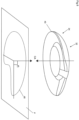
- Fig. 1A illustrates the structure of an ear 10.
- the term "ear” relates to a human ear.
- the ear 10 may also be referred to as pinna or auricle.
- the ear 10 comprises a helix 12 tracing the periphery of the ear upwards and inwards towards the skull wherein it transitions into the crus of helix 14.
- Fig. 1A illustrates that the ear 10 comprises a tragus 16, an antitragus 18 and an antihelix 20. Moreover, a concha cavity 22 is at least partially delimited by the tragus 16, an antitragus 18 and an antihelix 20. Moreover, Fig. 1A illustrates an ear canal 24.
- Fig. 1B illustrates a cross-sectional view of the Fig. 1A ear 10.
- the concha cavity 22 is at least partially delimited by a concha floor 26, a concha side wall 28 and a concha ceiling 30.
- the concha ceiling 30 may be formed by one or more components of the ear, such as at least portions of the tragus 16, antitragus 18 and antihelix 20.
- the concha side wall 28 connects the concha floor 26 to the concha ceiling 30.
- the surface of the concha ceiling 30 has a normal 32, at least a component of which is directed towards the concha floor 26.
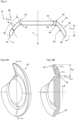
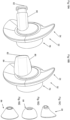
- Figs. 2A to Fig. 2C illustrate an embodiment of a peripheral skirt 34 comprising a positioning skirt portion 36 which in turn comprises an outer skirt surface 38 and an inner skirt surface 68, wherein a transition from the outer skirt surface 38 to the inner skirt surface 68 occurs at a skirt edge 40.
- a transition from the outer skirt surface 38 to the inner skirt surface 68 occurs at a skirt edge 40.
- each one of the inner and outer skirt surfaces 68, 38 terminates at the skirt edge 40.
- the positioning skirt portion 36 constitutes the complete peripheral skirt 34.
- the peripheral skirt 34 may comprise skirt portions (not shown in Fig. 2A ) in addition to the positioning skirt portion 36.
- the earpiece comprises a frame 42 adapted to receive a housing (not shown) for the earpiece 32.
- embodiments of the earpiece may be such that a housing is directly attached to the peripheral skirt 34 or that the peripheral skirt 34 and the housing form a unitary component (not shown in Figs. 2A to Fig. 2C ).
- Fig. 2B illustrates the peripheral skirt 34 in a condition before portions of the earpiece 32 have been inserted into an ear 10. Moreover, in the condition illustrated in Fig. 2B , no external loads are imparted the said peripheral skirt 34. As such, Fig. 2B illustrates the peripheral skirt 34 in a non-influenced condition.
- the skirt edge 40 extends at least partially circumferentially around a central axis CA of the earpiece 32.
- Fig. 2B illustrates that the earpiece 32 is adapted to be moved to a use position, at least partially within the concha cavity 22, in a direction parallel to the central axis CA, during insertion of the earpiece 32 into the ear 10.
- Fig. 2B also illustrates that, when the peripheral skirt 34 is in a non-influenced condition, at least a portion of the inner skirt surface 68 faces the central axis CA. As such, at least a portion of the positioning skirt portion 36 is slanted. In the Fig. 2B example, both sides of the positioning skirt portion 36 illustrated therein are slanted. Thus, though purely by way of example, at least a portion of the skirt edge 40 may be adapted to be deflected in a direction towards the central axis CA to thereby allow that the positioning skirt portion 36 can be moved to the use position. Such possible deflections are indicated by the arrows at the bottommost portion of Fig. 2B .
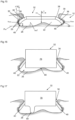
- the earpiece 32 is such that the positioning skirt portion 36 is adapted to assume the use position at least partially within the concha cavity 22 whereby:
- the condition that the skirt edge 40 is spaced from the concha floor 26 may be determined in one or more of ways.
- an earpiece in accordance with the present disclosure may be placed in a use position least partially within the concha cavity 22 of a user. The user may thereafter present information as to whether or not he or she experiences a contact between the skirt edge 40 and the concha floor 26.
- a substance such as paint, may be applied to the skirt edge 40 prior to inserting the positioning skirt portion 36 at least partially within the concha cavity 22.
- the earpiece 32 may thereafter be removed from the ear 10 and it may thereafter be possible to e.g. visually assess whether or not the skirt edge 40 has been in contact with the concha floor 26.
- the earpiece 32 is prevented from moving away from the concha floor 26, i.e. upwards in Fig. 2C , by virtue of the contact between at least a portion of the outer skirt surface 38 and at least a portion of the concha ceiling 30. Furthermore, in the Figs. 2A to 2C embodiment, the earpiece 32 is prevented from moving further towards the concha floor 26, i.e. downwards in Fig. 2C , by virtue of contact forces between at least portions of the skirt edge 40 and portions of the concha side wall 28. However, as will be presented hereinbelow, the earpiece 32 is prevented from moving further towards the concha floor 26 using means instead of or in addition to the skirt edge 40.
- the skirt edge 40 may be a free skirt edge such that no additional component of the earpiece 32 is located between the skirt edge and the ear 10, for instance the concha floor 26, when the earpiece 32 is in the use position.
- the earpiece 32 may be such that the positioning skirt portion 36 is adapted to assume a use position at least partially within the concha cavity 22 whereby, for every portion along the skirt edge 40, an airgap 43 is formed between the skirt edge 40 and the concha floor 26.
- the Fig. 2C embodiment of the peripheral skirt 34 may be such that the positioning skirt portion 36 is adapted to assume the use position at least partially in the concha cavity 22, whereby a minimum distance d min between the skirt edge 40 and the concha floor 22, as seen along a central axis CA of the earpiece 32, is at least 0.5 mm, preferably at least 1.0 mm, more preferred at least 1.5 mm.
- the minimum distance may be determined using the above-mentioned procedure involving the use of a substance, such as paint or ink.
- Fig. 3 illustrates a cross-sectional side view of an embodiment of a peripheral skirt 34
- Fig. 3 illustrates the positioning skirt portion 36 of the earpiece 32.
- Fig. 3 illustrates a radial axis R being perpendicular to the central axis CA.
- the central axis CA and the radial axis R define a plane, which is the plane of Fig. 3 .
- the positioning skirt portion 36 comprises a segment 37, extending between two distinct positions 37', 37" along the radial axis R.
- the segment 37 is such that, when the peripheral skirt 34 is in the non-influenced condition, each one of the inner skirt surface 68 and the outer skirt surface 38 associated with the segment 37 is located on the same side of the skirt edge 40, as seen along the central axis CA.
- the positioning skirt portion 36 comprises a "raised" portion with respect to the skirt edge 40.
- the distance between the two distinct positions 37', 37", as seen along the radial axis R may be equal to or greater than 40%, more preferred 80%, of the radial extension of the positioning skirt portion 36 which includes the two distinct positions 37', 37".
- the two distinct positions 37', 37" may actually be selected such that the distance between the two distinct positions 37', 37", as seen along the radial axis R, substantially equals the radial extension of the positioning skirt portion 36.
- Fig. 3 further illustrates that the outer skirt surface 38 may comprise an outer skirt surface distal point 39 located farthest away from the skirt edge 40, as seen along the outer skirt surface 38.
- the inner skirt surface 68 comprises an inner skirt surface distal point 69 located farthest away from the skirt edge 40, as seen along the inner skirt surface 68.
- each one of the outer skirt surface distal point 39 and the inner skirt surface distal point 69 may be located at a frame 42 which has been discussed hereinabove.
- each one of the outer skirt surface distal point 39 and the inner skirt surface distal point 69 may be located at an intersection between the positioning skirt portion 36 and a housing (not shown in Fig. 3 ) when the peripheral skirt 34 is connected to such a housing.
- the outer skirt surface distal point 39 may be separate from the inner skirt surface distal point 69. Further, in the Fig. 3 example, at least a portion of the positioning skirt portion 36 is such that, when the peripheral skirt 34 is in the non-influenced condition, each one of the outer skirt surface distal point 39 and the inner skirt surface distal point 69 are located on the same side of the skirt edge 40, as seen along the central axis CA.
- Fig. 3 illustrates an embodiment of the peripheral skirt 34 in which an outer surface distance L 1 , as measured along the central axis CA, from the outer skirt surface distal point 39 to the skirt edge 40 is greater than an inner surface distance L 2 , as measured along the central axis CA, from the inner skirt surface distal point 69.
- the positioning skirt portion 36 may comprise a neutral layer 35 located halfway between the inner skirt surface 68 and the outer skirt surface 38, as seen in a direction parallel to a normal n to the outer skirt surface 38.
- the neutral layer may be regarded as being located at half the thickness of the positioning skirt portion 36.
- the neutral layer 35 of at least a portion of the positioning skirt portion 36 is such that it, as seen in a plane defined by the central axis CA and the radial axis R and when the peripheral skirt 34 is in the previously discussed non-influenced condition, comprises a first neutral layer point 41 and a second layer point 45 separated by a distance L nlp along the radial axis R.
- a neutral layer line 47 extending through each one of the first and second neutral layer points 41, 45 forms a line angle ⁇ to the central axis CA.
- the line angle ⁇ may be within the range of 15 - 65°.
- At least a portion of the neutral layer 35 is such that a neutral layer line 47 extending therethrough may form a line angle ⁇ within the above-mentioned range.
- a portion may be relatively large.
- the portion may be such that the distance L nlp between the first and second neutral layer points 43, 45, as seen along the radial axis R, is equal to or greater than 40%, more preferred 80%, of the radial extension L nl of the total neutral layer containing the first and second neutral layer points 43, 45.
- Fig. 4 illustrates an embodiment of the peripheral skirt 34 in which a skirt edge-free angular sector 44 with its origin in the central axis CA is such that the angular sector 44 is free from the skirt edge 40.
- the skirt edge-free angular sector 44 has a skirt edge-free angular sector angle ⁇ of at least 45°, preferably at least 90°.
- the skirt edge-free angular sector 44 implies that the earpiece can be placed in an appropriate use position without necessarily abutting e.g. the crus of helix (see reference numeral 14 in Fig. 1A ) of an ear 10.
- skirt edge-free angular sector angle ⁇ may be smaller than or equal to 320°, preferably smaller than or equal to 270°, more preferred smaller than or equal to 180°.
- the skirt edge-free angular sector 44 can be regarded as a cut-out in the peripheral skirt 34 in the Fig. 4 embodiment. However, it is also possible to obtain embodiments of the earpiece 32 with the skirt edge-free angular sector 44 without using a cut-out. To this end, reference is made to the embodiment illustrated in Fig. 5 .
- the Fig. 5 embodiment comprises a peripheral skirt 34, one portion of which being the positioning skirt portion 36 and an additional skirt portion 46 being shaped such that it is not adapted to assume a use position at least partially within the concha cavity 22 when the earpiece 32 is in a use position.
- the additional skirt portion 46 does not comprise an outer skirt surface, as a consequence of which the additional skirt portion 46 does not terminate in a skirt edge within the meaning of the present disclosure.
- skirt edge-free angular sector 44 with the skirt edge-free angular sector angle ⁇ is obtained in the Fig. 5 embodiment by virtue of the upwardly bent shape of the additional skirt portion 46.
- Fig. 6 illustrates that a projection of the peripheral skirt 34, when the peripheral skirt 34 is in the non-influenced condition, onto a plane P, the normal n of which coincides with the central axis CA, has an outer contour 48 and the central axis CA is located within the outer contour.
- the central axis CA is positioned such that a minimum difference is obtained between a largest distance and a smallest distance from the central axis CA to the outer contour 48, as measured in the plane P.
- Fig. 7 illustrates the outer contour 48 of a peripheral skirt 34 of an earpiece 32 in accordance with the present disclosure.
- the Fig. 7 earpiece 32 comprises a maximum contour point 50 with a maximum distance R max in the plane P from the central axis CA to the outer contour 48.
- the Fig. 7 embodiment of the peripheral skirt 34 is such that an angular plane sector 52 with its origin in the central axis CA is such that the angular plane sector 52 is free from the peripheral skirt 34 and/or that the distance from the central axis CA to each point of the outer contour 48 in the angular plane sector 52 is less than 85% of the maximum distance R max .
- the angular plane sector 52 has an angular plane sector angle ⁇ of at least 40°, preferably at least 90°.
- a maximum contour point line 54 extending from the central axis CA to the maximum contour point 50 forms a smallest angle ⁇ with a line 56 defining the angular plane sector 52.
- the smallest angle ⁇ is in the range of 0 - 15°, preferably within the range of 0 - 5°.
- Fig. 8 illustrates that the peripheral skirt 34 may comprise a proximal contour point 58 with a proximal distance R prox in the plane P from the central axis CA to the outer contour 48.
- a ratio between the maximum distance R max and the proximal distance R prox may be equal to or greater than 1.1, preferably equal to or greater than 1.5.
- the outer contour 48 may be such that the distance from the central axis CA to the outer contour 48 increases gradually, preferably continuously, from the proximal contour point 58 to the maximum contour point 50. As such, the outer contour 48 may follow a spiral shape from the proximal contour point 58 to the maximum contour point 50.
- Fig. 8 further illustrates that the outer contour 48 further comprises an interim contour point 60 wherein the distance R interim from the central axis CA to the interim contour point 60 is greater than the proximal distance R prox but smaller than the maximum distance R prox .
- Fig. 8 illustrates that a largest angular segment with its origin in the central axis CA and which includes the maximum contour point 50, the proximal contour point 58 and the interim contour point 60 has an angle ⁇ of at least 40°, preferably at least 120°, more preferred at least 180°.
- the skirt edge 40 constitutes the outermost portion of at least portions of the peripheral skirt 34.
- embodiments of the earpiece 32 may comprise a peripheral skirt 34, portions of which being located at a larger distance from the central axis CA than a corresponding portion of the skirt edge 40.
- FIG. 9 An example of such an embodiment is illustrated in Fig. 9 .
- the peripheral skirt 34 is such that a maximum radial distance from the central axis to CA the outermost portion of the skirt 34 is larger than the radial distance from the central axis CA to the corresponding portion of the edge 40.
- a projection of the peripheral skirt 34 illustrated in Fig. 9 will not necessarily comprise any portion of the skirt edge 40.
- Fig. 10 illustrates a smallest circle 62 that circumscribes the outer contour 48 of a peripheral skirt 34.
- the diameter D of the smallest circle 62 may be within the range of 15 - 31 mm, preferably within the range of 19 - 27 mm, for embodiments of the earpiece 32.
- a portion of the peripheral skirt 34 may be such that it is adapted to be elastically deformed such that the distance in the plane from the central axis CA to the outer contour 48 of the portion can be elastically reduced by at least 5%.
- the portion of the peripheral skirt 34 that can be elastically deformed in accordance with the above forms part of the positioning skirt portion 36.
- Fig. 11 illustrates a cross-sectional side view of an embodiment of a peripheral skirt 34.
- the positioning skirt portion 36 comprises a distal portion 64 adapted to be located farthest away from the concha floor (not shown in Fig. 11 ), as seen along the central axis CA, when the positioning skirt portion 36 assumes the use position.
- the positioning skirt portion 36 extends at least partially from the distal portion 64 to the skirt edge 40.
- the distal portion 64 may be located at a frame 42 which has been discussed hereinabove.
- the distal portion 64 may be located at the intersection between the positioning skirt portion 36 and a housing (not shown in Fig. 11 ) when the peripheral skirt 34 is connected to such a housing.
- Fig. 11 illustrates a longest distance L max , when the peripheral skirt is in the non-influenced condition , as measured along the central axis CA, from the inner skirt surface distal point 69 to the skirt edge 40.
- the longest distance L max may be in the range of 1 - 8 mm, preferably in the range of 2 - 6 mm.
- a material thickness t of the positioning skirt portion is defined as the distance between the inner skirt surface 68 and the outer skirt surface 38, as seen in a direction parallel to the normal n to the outer skirt surface.
- the expression "material thickness” indicates that a value of the "material thickness” can only be determined for portions of the position skirt comprising skirt material between the inner skirt surface 68 and the outer skirt surface 38.
- Fig. 11 illustrates that the positioning skirt portion 36 may comprise an elongate portion 70 being such that an elongate portion length L elong , being the distance of the elongate portion 70 along the outer skirt surface 38 from the distal portion 64 to the skirt edge 40, is greater than an average material thickness of the elongate portion 70, when following the elongate portion 70 from the distal portion 64 to the skirt edge 40.
- the elongate portion length L elong is at least 1.05 times, preferably the elongate portion length L elong is at least 1.5 times, more preferred the elongate portion length L elong is at least twice, the average material thickness of the elongate portion 70.
- At least a portion of the skirt edge 40 may be adapted to be deflected, relative to the distal portion 64, in a direction towards the central axis CA to thereby allow that the positioning skirt portion 36 can be moved to the use position.
- each one of two portions of the skirt edge 40 being located on opposite sides of the central axis CA, is adapted to be deflected, relative to the distal portion 64, in a direction towards the central axis CA to thereby allow that the positioning skirt portion 36 can be moved to the use position.
- the above discussed portions of the skirt edge 40 may instead and/or in addition be adapted to be deflected relative to the housing 78.
- Figs. 12A and 12B illustrate another embodiment of the peripheral skirt 34.
- a minimum material thickness t min of the positioning skirt portion 36 is less than 75% of a maximum material thickness t max of the positioning skirt portion 36.
- a portion with the minimum material thickness t min is, in the Fig. 12A and Fig. 12B embodiment, located at a minimum material thickness distance r min - as seen along the radial axis R - from the distal portion 64.
- the minimum material thickness distance r min may be in the range of 0 - 80%, preferably in the range of 0 - 40%, more preferred in the range of 0 - 25%, of the distance r dist from the distal portion 64 to the skirt edge 40, as seen along the radial axis R.
- the portion with the minimum material thickness t min may be regarded as a weakening of the positioning skirt portion 36 which allows the positioning skirt portion 36 to be deformed so as to be inserted at least partially within the concha cavity (not shown in Fig. 12A or Fig. 12B ).
- the weakening may act as a hinge for the positioning skirt portion 36.
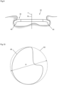
- Fig. 13 illustrates another embodiment wherein the positioning skirt portion 36 comprises a plurality of openings 72 extending from the inner skirt surface 68 to the outer skirt surface 38.
- peripheral skirt 34 which have been presented so far have comprised a circumferentially continuous positioning skirt portion with a circumferentially continuous skirt edge, it is also envisaged that embodiments of the peripheral skirt 34 of the present disclosure may comprise a circumferentially discontinuous positioning skirt portion.
- Fig. 14 illustrates an embodiment of the peripheral skirt 34 wherein the positioning skirt portion 36 thereof comprises a plurality of circumferentially separated positioning skirt portion tongues 74.
- Each positioning skirt portion tongue 74 extends with an increasing distance from the central axis CA to a positioning skirt portion tongue edge 76 forming part of the skirt edge 40.
- the skirt 34 comprises portions of a resilient polymer having a Shore A durometer within the range of 25 - 90.
- the skirt 34 may be constituted by a resilient polymer having a Shore A durometer within the range of 25 - 90.
- the resilient polymer comprises, alternatively, is constituted by, silicone or a thermoplastic elastomer.
- the material examples listed above may be used for any embodiment of the earpiece 32 of the present disclosure.
- the concha ceiling which at least a portion of said outer skirt surface 38 is adapted to abut when the positioning skirt portion 36 assumes the use position, comprises a ceiling portion from at least one of the following portions of the ear: an antihelix 20, a tragus 16 and an antitragus 18.
- the concha ceiling comprises a ceiling portion from the antihelix 20.
- the earpiece 32 may be such that the positioning skirt portion 36 is adapted to assume a use position at least partially within the concha cavity 22 whereby,
- Fig. 15 illustrates another embodiment of the peripheral skirt 34.
- the positioning skirt portion 36 is adapted to assume the use position at least partially in the concha cavity 22 such that at least a portion of the skirt edge 40 abuts at least a portion of the concha side wall 28, thereby preventing the skirt edge 40 from contacting the concha floor 26 in addition to a movement-prevention member as will be discussed below.
- the positioning skirt portion 36 is preferably such that the size and shape of the skirt edge 40 results in a contact between the skirt edge 40 and at least a portion of the concha side wall 28.
- the positioning skirt portion 36 may be such that the skirt edge 40 is pressed outwards towards the concha side wall 28 when the skirt portion 36 assumes the use position.
- the skirt edge 40 may pressed outwards if the positioning skirt portion 36 is associated with a line angle ⁇ within the range of 15 - 65 ° as has been discussed hereinabove with reference to Fig. 3 .
- the concha floor 22 has a concha main floor plane P mf with a concha main floor plane normal n mf extending in a concha floor normal direction out from the ear 10.
- the concha side wall 28 forms an angle of 30° or less to the concha floor normal direction.
- the concha side wall 28 may be presented such that the normal n csw of two concha side wall portions, located on opposite sides of the central axis CA, are directed towards each other. Such a scenario also is indicated in Fig. 15 .
- embodiments of the earpiece 32 further comprise a movement-prevention member adapted to prevent the positioning skirt portion 38 from moving relative to the concha floor 22 to a position in which at least a portion of the skirt edge 40 contacts the concha floor 22. Implementations of such a movement-prevention member will be discussed hereinbelow with reference to Figs. 16 - 20 .
- the earpiece 32 further comprises a housing 78, wherein the peripheral skirt 34 at least partially circumscribes the housing 78.
- the housing 78 may be connected to the peripheral skirt 34 via a frame (not shown in Fig. 16 ) or the housing 78 may be directly attached to the peripheral skirt 34, alternatively the peripheral skirt 34 and the housing 78 may form a unitary component.
- the Fig. 16 housing 78 comprises a concha floor abutment portion 80.
- the concha floor abutment portion 80 forms at least part of the movement-prevention member.
- the earpiece 32 is such that the housing 78 is adapted to assume a use position at least partially within the concha cavity 22 in which the concha floor abutment portion 80 abuts the concha floor 26, thereby preventing the skirt edge 40 from contacting the concha floor 26.
- the earpiece 32 may comprise a sensor (not shown) for detecting contact between housing 78 and concha floor 26.
- a sensor may be accommodated within the housing 78.
- the portion of the housing 78 that is adapted to face the concha floor 26 is relatively flat.
- the concha floor abutment portion 80 may protrude from the remaining portion of the housing 78.
- An example of such an embodiment is illustrated in Fig. 17 .
- the concha floor abutment portion 80 may be adapted to abut a portion of the concha floor 26 at or around the ear canal (not shown in Fig. 17 ) of the ear 10.
- the concha floor abutment portion 80 may comprise means, such as an audio duct opening, for guiding sound from the at least a portion of the housing 78, for instance from a sound emitting component of the housing 78, to the ear canal.
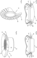
- Fig. 18A illustrates an embodiment of the earpiece 32 in which the above-mentioned concha floor abutment portion 80 is implemented as a nozzle extending from the housing 78.
- the Fig. 18A nozzle 80 comprises an audio duct opening 82.
- the length of the nozzle 80 may be fixed.
- the length of the nozzle 80 may be varied such that the length may be adapted to the user of the earpiece 32.
- the length may be varied manually or using an actuator (not shown) associated with the earpiece 32.
- the nozzle 80 may be adapted to be bent relative to another portion of the housing 78.
- the earpiece 32 for instance the nozzle 80 and/or another portion of the housing 78, may comprise a joint (not shown) allowing the nozzle 80 to be bent or deflected relative to another portion of the housing 78.
- the possibility to adjust the length and/or the angle of the nozzle 80 relative to another portion of the housing 78 implies an increased flexibility for a user to adjust the earpiece 32 to the user's ear.
- Fig. 18B illustrates the Fig. 18A embodiment of the earpiece 32 although an eartip 84 has been fitted onto the nozzle 80. It should be noted that the nozzle 80 may be furnished with an eartip irrespective of whether the nozzle 80 is fixed, adjustable in length and/or adjustable in angle as mentioned hereinabove.
- Fig. 18C to Fig. 18E illustrate implementations of eartips for fitting onto a nozzle 80, such as the Fig. 18A nozzle 80.
- Fig. 18C illustrates an eartip 84 that is intended to be positioned in a sub tragic region immediately covered by the tragus.
- the Fig. 18C implementation may provide a comfortable fit without having to touch the ear canal or the opening of the ear canal.
- the Fig. 18C embodiment can provide some ambient sound into the ear and can be beneficial for mobile phone use.
- FIG. 18D and Fig. 18E illustrates a frustoconical eartip 84 that provides a close fit against the opening of the ear canal which may substantially eliminate ambient sound.
- the housing 78 may further comprise sound emitting means, such as a loudspeaker.
- the movement-prevention member comprises an outward abutment portion 86.
- the outward abutment portion 86 is adapted to abut a portion of the ear 10 being opposite to the concha ceiling 30 when the earpiece 32 assumes a use position.
- the outward abutment portion 86 may be adapted to abut an outer part of the antihelix 20 of the ear when the earpiece assumes the use position.
- a portion of the ear is squeezed or nipped between at least a portion of the outer skirt surface 38 and at least a portion of the outward abutment portion 86.
- This will in turn ensure that the earpiece 32 is kept in place such that the skirt edge 40 is prevented from contacting the concha floor 26.
- the fact that a portion of the ear is squeezed or nipped between at least a portion of the outer skirt surface 38 and at least a portion of the outward abutment portion 86 makes it possible to determine useful information as regards the status, such as temperature or pulse, of the user of the earpiece 32.
- the embodiments of the earpieces 32 disclosed therein may comprise a sensor assembly 88.
- the sensor assembly may comprise a transmitter in or on the outward abutment portion 86 and a receiver in or on the positioning skirt portion 36, or vice versa.
- Fig. 21 illustrates another embodiment of the peripheral skirt of the present disclosure wherein at least the outer skirt surface 38 is pleated.
- the positioning skirt portion corresponds to the peripheral skirt, which is pleated.
- a surface roughness of the outer skirt surface is equal to or greater than 0.1 mm.
- Fig. 22 illustrates an example of the earpiece 32 not covered by the scope of the appended claims wherein the earpiece 32 further comprises sound emitting means 86 preferably a loudspeaker.
- the sound emitting means may be accommodated in a housing 78 of the earpiece 32.
- the earpiece 32 may be used for other applications.
- embodiments of the earpiece 32 may be used as an earplug for protecting a user's ears from loud noises.
- the earpiece 32 may comprise attachment means for connection to a sidepiece of a pair of glasses (not shown).
- the earpiece 32 - for instance the housing thereof - may comprise electronic components in addition to components needed for sound emission.
- embodiments of the earpiece 32 may comprise components for issuing or receiving wireless signals.
Description
- The present disclosure relates to an earpiece for an ear.
- An earpiece for an ear may be used in many applications. For instance, an earpiece may be used as an earplug for protecting a user's ears from loud noises. Another application for an earpiece is when the earpiece constitutes, or at least forms part of, an earphone arrangement. For instance, an earpiece may comprise sound emitting means, such as a loudspeaker, adapted to direct sound into the ear canal of the ear.
- Irrespective of the intended use of an earpiece, it is generally desired that the earpiece is such that it is kept in place relative to a user's ear. An example of such an earpiece is presented in
WO 2008/147215 A1 . Although the earpiece disclosed inWO 2008/147215 A1 is suitable for many applications, there is still a need for improving the design of the earpiece. - According to its abstract,
US2018/167713 A1 is directed to a headphone or an earpiece that includes a cushion that advantageously allows for improved comfort, sound quality, and stability in the ear. The cushion includes an inner cavity, an ear-canal aperture and a tip portion, wherein the inner cavity of the cushion accommodates a nozzle portion of a housing within the cavity, and the axis of the inner cavity is substantially parallel to the first axis, wherein the ear-canal aperture opens toward the ear canal of the user's ear when the headphone or the earpiece is worn by the user, and wherein the tip portion engages the concha of the user's ear when the headphone or the earpiece is worn by the user, and the axis of the tip portion is not parallel to the first axis. - According to its abstract,
WO2017/183027 A1 relates to an earbud for use with, for example, a media player or a smartphone. The earbud includes a housing enclosing a speaker and an optical sensor positioned on the housing such that the optical sensor contacts a surface of tragus when the earbud is positioned in an ear with the speaker directed into an ear canal. The earbud further includes a stabilizing element attachable to the housing and configured for contacting a posterior wall of a cavum or incisura of the ear when the earbud is positioned in the ear with the speaker directed into the ear canal. - According to its abstract,
US2014/286515 A1 relates generally to an apparatus for retaining an earpiece in the ear during physical movement and exercise. In various instances, the apparatus may include a thinned region a posterior arch and ribs to allow deformation of the earmold and facilitate securing of the earmold in the concha bowl of the ear. - According to its abstract,
US2019/200112 A1 relates to an earpiece including a housing and a speaker within the housing. The earpiece can also include an earbud and a protrusion carried by the housing. The earbud can extend from the housing toward a canal of a user's ear when the earpiece is mounted to the user's ear. The protrusion can be at least partially received within a recess at least partially defined by a cymba concha of the user's ear and by an anterior ridge of an antihelix of the user's ear when the earpiece is mounted to the user's ear. The protrusion can include resilient members and intervening slots. The individual resilient members can be configured to preferentially bend relative to the housing in a direction parallel to an adjacent length of the anterior ridge when the earpiece is mounted to the user's ear. - An object of the present disclosure is to provide an earpiece that can be kept in place relative to a user's ear and which earpiece is also comfortable to use.
- The above object is achieved by an earpiece in accordance with
claim 1. - As such, the present disclosure relates to an earpiece for an ear. The ear comprises a concha cavity at least partially delimited by a concha floor, a concha side wall and a concha ceiling, wherein the concha side wall connects the concha floor to the concha ceiling. The surface of the concha ceiling has a normal at least a component of which being directed towards the concha floor.
- The earpiece comprises a peripheral skirt comprising a positioning skirt portion which in turn comprises an outer skirt surface and an inner skirt surface, wherein a transition from the outer skirt surface to the inner skirt surface occurs at a skirt edge. Purely by way of example, each one of the outer skirt surface and the inner skirt surface terminates at the skirt edge.
- The skirt edge extends at least partially circumferentially around a central axis of the earpiece. The earpiece is adapted to be moved to a use position, at least partially within the concha cavity, in a direction parallel to the central axis, during insertion of the earpiece into the ear.
- When the peripheral skirt is in a non-influenced condition, at least a portion of the inner skirt surface faces the central axis. As used herein, the expression "non-influenced condition" is intended to mean that the peripheral skirt is not in the use position or in another condition, such as in a condition in which the positioning skirt portion is in the process of being at least partially inserted into the concha cavity, in which the peripheral skirt is imparted external loads.
- According to the present disclosure, the earpiece is such that the positioning skirt portion is adapted to assume the use position at least partially within the concha cavity whereby:
- at least a portion of the outer skirt surface abuts at least a portion of the concha ceiling,
- the skirt edge is located closer to the concha floor than the outer skirt surface, and
- the skirt edge is spaced from the concha floor.
- As such, the earpiece according to the present disclosure comprises a positioning skirt portion that can assist in maintaining the position of the earpiece relative to an ear, by virtue of the outer skirt surface. Moreover, the fact that the skirt edge is spaced from the concha floor of the ear during use implies a comfortable use condition. Thus, the earpiece in accordance with the present disclosure implies the combination of an appropriately durable connection between the earpiece and the ear at the same time as an appropriately comfortable use position can be obtained.
- For instance, by virtue of the fact that the skirt edge does not contact the concha floor, air may be circulated between the concha floor and edge which in turn implies a desired comfort for the user. Put differently, the earpiece according to the present disclosure implies an appropriately low footprint on the concha floor.
- Furthermore, the feature that at least a portion of the inner skirt surface faces the central axis in a non-influenced condition implies that at least a portion of the positioning skirt portion is slanted. This in turn implies that at least a portion of the positioning skirt portion may be deflected in a straightforward manner by a user when the positioning skirt portion is to assume the use position. The fact that at least a portion of the positioning skirt portion is slanted implies that this portion may be deflected by means of bending towards the central axis. When the positioning skirt portion is approaching the use position, the positioning skirt portion may be relaxed and move towards its non-influenced condition which implies an appropriate contact between the outer skirt surface and the concha ceiling. Moreover, the above-mentioned relaxation of the positioning skirt portion may also imply an appropriate contact between the skirt edge and the concha side wall, which in turn may assist in preventing the skirt edge from contacting the concha floor.
- Optionally, the skirt edge is a free skirt edge. By the term "free skirt edge", it is meant that no additional component of the earpiece is located between the skirt edge and the concha floor when the earpiece is in the use position. The feature that the skirt edge is a free skirt edge can be used in any embodiment of the present disclosure and in each one of the appended claims.
- Optionally, the above-mentioned transition from the outer skirt surface to the inner skirt surface occurring at the skirt edge is such that the portions of the inner and outer skirt surfaces, respectively, adjacent to the skirt edge form an angle of at least 120°, preferably at least 150°, to each other, as seen in a plane defined by the central axis and a radial axis being perpendicular to the central axis. The above feature relating to adjacent portions to the edge can be used in any embodiment of the present disclosure and in each one of the appended claims.
- Optionally, the skirt edge may have a radius of curvature within the range of 0.1 - 3 mm, preferably within a range of 0.5 - 2 mm, as seen in a plane defined by the central axis and a radial axis being perpendicular to the central axis. The above feature relating to the radius of curvature of the skirt edge can be used in any embodiment of the present disclosure and in each one of the appended claims. When the skirt edge has an extension, unless otherwise indicated, any distance between the skirt edge and another entity is intended to mean a maximum distance from the skirt edge to that entity throughout the present application.
- As seen in a plane defined by the central axis and a radial axis being perpendicular to the central axis, the positioning skirt portion comprises a segment, extending between two distinct positions along the radial axis, being such that, when the peripheral skirt is in the non-influenced condition, each one of the inner skirt surface and the outer skirt surface associated with the segment is located on the same side of the skirt edge, as seen along the central axis. Such an implementation will further enhance the possibilities to deflect a portion of the positioning skirt portion by means of bending towards the central axis. Optionally, the outer skirt surface comprises an outer skirt surface distal point located farthest away from the skirt edge, as seen along the outer skirt surface. Moreover, the inner skirt surface comprises an inner skirt surface distal point located farthest away from the skirt edge, as seen along the inner skirt surface. The outer skirt surface distal point is separate from the inner skirt surface distal point. At least a portion of the positioning skirt portion is such that, when the peripheral skirt is in the non-influenced condition, each one of the outer skirt surface distal point and the inner skirt surface distal point are located on the same side of the skirt edge, as seen along the central axis.
- As such, as viewed from the inner and outer skirt surface distal points towards the skirt edge, at least a portion of the positioning skirt portion is slanted towards the skirt edge which will enhance the possibility to bend the edge towards the central axis.
- As intimated hereinabove, the skirt edge is located closer to the concha floor than the outer skirt surface when the positioning skirt portion assumes its use position. As such, the expression "on the same side" used above results in locations such that skirt edge is located between the relevant portions of the inner and outer surfaces and the concha floor when the earpiece is moved in a direction towards the concha floor.
- Optionally, an outer surface distance, as measured along the central axis, from the outer skirt surface distal point to the skirt edge is greater than an inner surface distance, as measured along the central axis, from the inner skirt surface distal point.
- Optionally, when the peripheral skirt is in the non-influenced condition, a longest distance, as measured along the central axis, from the inner skirt surface distal point to the skirt edge is in the range of 1 - 8 mm, preferably in the range of 2 - 6 mm.
- Optionally, the positioning skirt portion comprises a neutral layer located halfway between the inner skirt surface and the outer skirt surface, as seen in a direction parallel to a normal to the outer skirt surface. The neutral layer of at least a portion of the positioning skirt portion is such that it, as seen in a plane defined by the central axis and a radial axis being perpendicular to the central axis and when the peripheral skirt is in the non-influenced condition, comprises a first neutral layer point and a second neutral layer point separated by a distance along the radial axis. A neutral layer line extending through each one of the first and second neutral layer points forms a line angle to the central axis. The line angle is within the range of 15 - 65 °.
- Again, the skirt edge is located closer to the concha floor than the outer skirt surface when the positioning skirt portion assumes its use position. As such, the neutral layer line will intersect the central axis at an intersection point such that, as seen along the central axis, the skirt edge is located between the intersection point and the concha floor when the earpiece is moved in a direction towards the concha floor.
- A line angle within the mentioned range implies an appropriate contact between the at least a portion of the outer skirt surface and the at least a portion of the concha ceiling during use, as well as implying that the skirt edge can assume a suitable condition, for instance abutting the concha wall, when the positioning skirt portion assumes the use position. Moreover, a line angle within the mentioned range also implies that the at least a portion of the positioning skirt portion may be deflected towards the central axis, for instance by bending a portion of the of the positioning skirt portion towards the central axis. After insertion at least partially within the concha cavity, the previously deflected portion of the of the positioning skirt portion flexes back towards its non-influenced condition and a contact between the outer surface and at least a portion of the concha ceiling may thus be obtained in an appropriate manner.
- The line angle within the above range preferably applies for at least 30% of the positioning skirt portion, as seen along the circumferential direction of the outer skirt surface. Furthermore, the portion of the skirt comprising a maximum contour point, which will be discussed hereinbelow, is preferably such that the line angle is within the above range. Additionally, a portion of the positioning skirt portion comprising an elongate portion, which will be discussed hereinbelow, is preferably such that the line angle is within the above range.
- Optionally, the distance between the first and second neutral layer points, as seen along the radial axis, is equal to or greater than 40%, more preferred equal to or greater than 80%, of the radial extension of the total neutral layer containing the first and second neutral layer points.
- Optionally, the earpiece is such that the positioning skirt portion is adapted to assume a use position at least partially within the concha cavity whereby, for every portion along the skirt edge, an airgap is formed between the skirt edge and the concha floor. The airgap feature means that the earpiece does not comprise any component connecting the concha floor to the skirt edge when the positioning skirt portion assumes the use position.
- Optionally, a skirt edge-free angular sector with its origin in the central axis is such that the angular sector is free from the skirt edge. The skirt edge-free angular sector has a skirt edge-free angular sector angle of at least 45°, preferably at least 90°. The skirt edge-free angular sector implies that the earpiece can be placed in an appropriate use position without necessarily abutting e.g. the crus of helix of an ear.
- Optionally, the skirt edge-free angular sector angle is smaller than or equal to 320°, preferably smaller than or equal to 270°, more preferred smaller than or equal to 180°. A skirt edge-free angular sector angle smaller than any one of the above angles implies than an appropriately large contact area can be established between the outer skirt surface and the concha ceiling.
- Optionally, when the peripheral skirt is in the non-influenced condition, a projection of the peripheral skirt onto a plane, the normal of which coincides with the central axis, has an outer contour and the central axis is located within the outer contour. The central axis is positioned such that a minimum difference is obtained between a largest distance and a smallest distance from the central axis to the outer contour, as measured in the plane. The earpiece comprises a maximum contour point with a maximum distance in the plane from the central axis to the outer contour.
- Optionally, an angular plane sector with its origin in the central axis is such that the angular plane sector is free from the peripheral skirt and/or that the distance from the central axis to each point of the outer contour in the angular plane sector is less than 85% of the maximum distance. The angular plane sector has an angular plane sector angle of at least 40°, preferably at least 90°. An angular plane sector angle smaller than any one of the above angles implies that the earpiece can be placed in an appropriate use position without necessarily abutting e.g. the crus of helix of an ear.
- Optionally, a maximum contour point line extending from the central axis to the maximum contour point forms a smallest angle with a line defining the angular plane sector. The smallest angle is in the range of 0 - 15°, preferably within the range of 0 - 5°. A smallest angle within any one of the above ranges implies that the outer skirt surface can abut a portion of the concha ceiling which is located relatively high up the ear, for instance in the area of the antihelix without necessarily abutting e.g. the crus of helix of an ear.
- Optionally, the earpiece comprises a proximal contour point with a proximal distance in the plane from the central axis to the outer contour, wherein a ratio between the maximum distance and the proximal distance is equal to or greater than 1.1, preferably equal to or greater than 1.5. A ratio within any one of the above ranges implies that the outer contour may be adapted to follow shape of ear portions delimiting a concha cavity.
- Optionally, the outer contour is such that the distance from the central axis to the outer contour increases gradually, preferably continuously, from the proximal contour point to the maximum contour point.
- Optionally, the outer contour further comprises an interim contour point wherein the distance from the central axis to the interim contour point is greater than the proximal distance but smaller than the maximum distance, wherein a largest angular segment with its origin in the central axis and which includes the maximum contour point, the proximal contour point and the interim contour point has an angle of at least 40°, preferably at least 120°, more preferred at least 180°.
- Optionally, a projection of the skirt edge onto the plane, the normal of which coincides with the central axis, coincides with at least a portion of the outer contour.
- Optionally, a smallest circle that circumscribes the outer contour has a diameter within the range of 15 - 31 mm, preferably within the range of 19 - 27 mm. A diameter within any one of the above ranges implies that the positioning skirt portion can be large enough to be able to contact various portions of an ear, thereby ensuring an appropriately connection between the positioning skirt portion and the ear.
- Optionally, the positioning skirt portion comprises a distal portion adapted to be located farthest away from the concha floor, as seen along the central axis, when the positioning skirt portion assumes the use position. The positioning skirt portion extends at least partially from the distal portion to the skirt edge.
- Optionally, at least a portion of the skirt edge is adapted to be deflected, relative to the distal portion, in a direction towards the central axis to thereby allow that the positioning skirt portion can be moved to the use position.
- Optionally, each one of two portions of the skirt edge, being located on opposite sides of the central axis, is adapted to be deflected, relative to the distal portion, in a direction towards the central axis to thereby allow that the positioning skirt portion can be moved to the use position.
- Optionally, a portion of the peripheral skirt is adapted to be elastically deformed such that the distance in the plane from the central axis to the outer contour of the portion can be elastically reduced by at least 5%. Preferably, the portion of the peripheral skirt that can be elastically deformed in accordance with the above forms part of the positioning skirt portion. An elastic deformation in accordance with the above implies that the insertion of the positioning skirt portion at least partially into the concha cavity can be carried out in a straightforward manner.
- Optionally, the positioning skirt portion comprises a plurality of openings extending from the inner skirt surface to the outer skirt surface. The plurality of openings may contribute to the comfort for the user since the openings may reduce the area of continuous contact between the outer skirt surface and the concha ceiling.
- Optionally, a material thickness of the positioning skirt portion is defined as the distance between the inner skirt surface and the outer skirt surface, as seen in a direction parallel to the normal to the outer skirt surface.
- Optionally, when following the positioning skirt portion from the distal portion to the skirt edge, a minimum material thickness of the positioning skirt portion is less than 75% of a maximum material thickness of the positioning skirt portion. The minimum thickness less than the above value implies that the positioning skirt portion comprises a relatively weaker portion that can deform and thus act as a hinge when the positioning skirt portion is at least partially inserted into the concha cavity.
- Optionally, a portion with the minimum material thickness is located at a minimum material thickness distance - as seen along a radial axis being perpendicular to the central axis - from the distal portion, the minimum material thickness distance being in the range of 0 - 80%, preferably in the range of 0 - 40%, more preferred in the range 0 - 25%, of the distance from the distal portion to the skirt edge, as seen along the radial axis. A minimum material thickness distance within the above range implies that the deformation of the positioning skirt portion occurs at a suitable location which simplifies the insertion of the positioning skirt portion at least partially into the concha cavity.
- Optionally, the positioning skirt portion comprises an elongate portion being such that an elongate portion length, being the distance of the elongate portion along the outer skirt surface from the distal portion to the skirt edge, is greater than an average material thickness of the elongate portion, when following the elongate portion from the distal portion to the skirt edge. Preferably, the elongate portion length is at least 1.05 times, preferably the elongate portion length is at least 1.5 times, more preferred the elongate portion length is at least twice, the average material thickness of the elongate portion.
- Optionally, the skirt comprises portions of a resilient polymer having a Shore A durometer within the range of 25 - 90. Preferably, the resilient polymer comprises silicone or a thermoplastic elastomer.
- Optionally, the positioning skirt portion comprises a plurality of circumferentially separated positioning skirt portion tongues, each positioning skirt portion tongue extending with an increasing distance from the central axis to a positioning skirt portion tongue edge forming part of the skirt edge.
- Optionally, the concha ceiling, which at least a portion of the outer skirt surface is adapted to abut when the positioning skirt portion assumes the use position, comprises a ceiling portion from at least one of the following portions of the ear: an antihelix, a tragus and an antitragus. Preferably, the concha ceiling comprises a ceiling portion from the antihelix.
- Optionally, the earpiece is such that the positioning skirt portion is adapted to assume a use position at least partially within the concha cavity whereby,
- a first portion of the outer skirt surface abuts a ceiling portion of the antihelix, and
- a second portion of the outer skirt surface abuts a ceiling portion of the antitragus.
- Optionally, the earpiece is such that the positioning skirt portion is adapted to assume the use position at least partially in the concha cavity, whereby a minimum distance between the skirt edge and the concha floor, as seen along the central axis of the earpiece, is at least 0.5 mm, preferably at least 1.0 mm, more preferred at least 1.5 mm. Such a minimum distance implies an appropriate degree of comfort for the user.
- Optionally, the positioning skirt portion is adapted to assume the use position at least partially in the concha cavity such that at least a portion of the skirt edge abuts at least a portion of the concha side wall, thereby preventing the skirt edge from contacting the concha floor. As such, the contact between the skirt edge and the concha side wall can contribute to preventing the skirt edge from contacting the concha floor when the positioning skirt portion assumes the use position.
- Optionally, the concha floor has a concha main floor plane with a concha main floor plane normal extending in a concha floor normal direction out from the ear, the concha side wall forming an angle of 30° or less to the concha floor normal direction.
- Optionally, the concha side wall is such that the normal of two concha side wall portions, located on opposite sides of the central axis, are directed towards each other.
- Optionally, the earpiece further comprises a housing, wherein the peripheral skirt at least partially circumscribes the housing.
- Optionally, at least a portion of the skirt edge is adapted to be deflected, relative to the housing, in a direction towards the central axis to thereby allow that the positioning skirt portion can be moved to the use position.
- Optionally, each one of two portions of the skirt edge, located on opposite sides of the central axis, is adapted to be deflected, relative to the housing, in a direction towards the central axis to thereby allow that the positioning skirt portion can be moved to the use position.
- According to appended
claim 1, the earpiece further comprises a movement-prevention member adapted to prevent the positioning skirt portion from moving relative to the concha floor to a position in which at least a portion of the skirt edge contacts the concha floor. - Optionally, the housing comprises a concha floor abutment portion forming at least part of the movement-prevention member. The earpiece is such that the housing is adapted to assume a use position at least partially within the concha cavity in which the concha floor abutment portion abuts the concha floor, thereby preventing the skirt edge from contacting the concha floor.
- Optionally, the movement-prevention member comprises an outward abutment portion. The outward abutment portion is adapted to abut a portion of the ear being opposite to the concha ceiling when the earpiece assumes a use position.
- Optionally, the outward abutment portion is adapted to abut an outer part of the antihelix of the ear when the earpiece assumes the use position.
- Optionally, at least the outer skirt surface is pleated, preferably at least the positioning skirt portion is pleated, more preferred the peripheral skirt is pleated.
- Optionally, a surface roughness of the outer skirt surface, as measured in a direction from the central axis to the skirt edge, is equal to or greater than 0.1 mm.
- Optionally, the earpiece further comprises sound emitting means, preferably a loudspeaker.
- Optionally, the earpiece further comprises attachment means for connection to a sidepiece of a pair of glasses.
- With reference to the appended drawings, below follows a more detailed description of embodiments of the disclosure cited as examples.
- In the drawings:
- Figs. 1A and 1B
- illustrate a human ear,
- Figs. 2A -2C
- illustrate an embodiment of a peripheral skirt,
- Fig. 3
- illustrates a cross-sectional side view of an embodiment of the peripheral skirt,
- Fig. 4
- illustrates another embodiment of the peripheral skirt,
- Fig. 5
- illustrates a further embodiment of the peripheral skirt,
- Fig. 6
- illustrates an outer contour of a peripheral skirt of an earpiece,
- Fig. 7
- illustrates an outer contour of a peripheral skirt of an embodiment of the earpiece,
- Fig. 8
- illustrates an outer contour of a peripheral skirt of another embodiment of the earpiece,
- Fig. 9
- illustrates a side view of a further embodiment of the peripheral skirt,
- Fig. 10
- illustrates an outer contour of a peripheral skirt of yet another embodiment of the earpiece,
- Fig. 11
- illustrates a cross-sectional side view of an embodiment of a peripheral skirt,
- Figs. 12A and 12B
- illustrate yet another embodiment of the peripheral skirt,
- Fig. 13
- illustrates a further embodiment of the peripheral skirt,
- Fig. 14
- illustrates another embodiment of the peripheral skirt,
- Fig. 15
- illustrates a cross-sectional side view of a further embodiment of a peripheral skirt,
- Fig. 16
- illustrates a cross-sectional side view of an embodimentof an earpiece,
- Fig. 17
- illustrates a cross-sectional side view of yet another embodiment of an earpiece,
- Figs. 18A - 18E
- illustrate still another embodiment of the earpiece,
- Fig. 19
- illustrates a cross-sectional side view of yet another embodiment of the earpiece,
- Fig. 20
- illustrates a cross-sectional side view of an additional embodiment of the earpiece,
- Fig. 21
- illustrates a perspective view of another embodiment of the peripheral skirt,
- Fig. 22
- illustrates a perspective view of an example of the earpiece not covered by the scope of the appended claims.
- Preferred embodiments of the present disclosure will be discussed hereinbelow with reference to the appended drawings. Throughout the application, any range should be construed as a closed range. Put differently, any range used in the application should be construed as including the end points of the range.
-
Fig. 1A illustrates the structure of anear 10. As used herein, the term "ear" relates to a human ear. Theear 10 may also be referred to as pinna or auricle. Theear 10 comprises ahelix 12 tracing the periphery of the ear upwards and inwards towards the skull wherein it transitions into the crus ofhelix 14. - Moreover,
Fig. 1A illustrates that theear 10 comprises atragus 16, anantitragus 18 and anantihelix 20. Moreover, aconcha cavity 22 is at least partially delimited by thetragus 16, anantitragus 18 and anantihelix 20. Moreover,Fig. 1A illustrates anear canal 24. -
Fig. 1B illustrates a cross-sectional view of theFig. 1A ear 10. As may be gleaned fromFig. 1B , theconcha cavity 22 is at least partially delimited by aconcha floor 26, aconcha side wall 28 and aconcha ceiling 30. As will be discussed below, theconcha ceiling 30 may be formed by one or more components of the ear, such as at least portions of thetragus 16,antitragus 18 andantihelix 20. Theconcha side wall 28 connects theconcha floor 26 to theconcha ceiling 30. Moreover, as indicated inFig. 1B , the surface of theconcha ceiling 30 has a normal 32, at least a component of which is directed towards theconcha floor 26. -
Figs. 2A to Fig. 2C illustrate an embodiment of aperipheral skirt 34 comprising apositioning skirt portion 36 which in turn comprises anouter skirt surface 38 and aninner skirt surface 68, wherein a transition from theouter skirt surface 38 to theinner skirt surface 68 occurs at askirt edge 40. Preferably, and as illustrated in e.g.Fig. 2A , each one of the inner and outer skirt surfaces 68, 38 terminates at theskirt edge 40. - In the embodiment illustrated in
Fig. 2A , thepositioning skirt portion 36 constitutes the completeperipheral skirt 34. However, in other embodiments of theearpiece 32, theperipheral skirt 34 may comprise skirt portions (not shown inFig. 2A ) in addition to thepositioning skirt portion 36. Furthermore, in theFig. 2A embodiment, the earpiece comprises aframe 42 adapted to receive a housing (not shown) for theearpiece 32. However, it is also envisaged that embodiments of the earpiece may be such that a housing is directly attached to theperipheral skirt 34 or that theperipheral skirt 34 and the housing form a unitary component (not shown inFigs. 2A to Fig. 2C ). -
Fig. 2B illustrates theperipheral skirt 34 in a condition before portions of theearpiece 32 have been inserted into anear 10. Moreover, in the condition illustrated inFig. 2B , no external loads are imparted the saidperipheral skirt 34. As such,Fig. 2B illustrates theperipheral skirt 34 in a non-influenced condition. - Furthermore, as may be gleaned from
Fig. 2B , theskirt edge 40 extends at least partially circumferentially around a central axis CA of theearpiece 32. Moreover,Fig. 2B illustrates that theearpiece 32 is adapted to be moved to a use position, at least partially within theconcha cavity 22, in a direction parallel to the central axis CA, during insertion of theearpiece 32 into theear 10. -
Fig. 2B also illustrates that, when theperipheral skirt 34 is in a non-influenced condition, at least a portion of theinner skirt surface 68 faces the central axis CA. As such, at least a portion of thepositioning skirt portion 36 is slanted. In theFig. 2B example, both sides of thepositioning skirt portion 36 illustrated therein are slanted. Thus, though purely by way of example, at least a portion of theskirt edge 40 may be adapted to be deflected in a direction towards the central axis CA to thereby allow that thepositioning skirt portion 36 can be moved to the use position. Such possible deflections are indicated by the arrows at the bottommost portion ofFig. 2B . - Furthermore, with reference to
Fig. 2C , theearpiece 32 according to the present invention is such that thepositioning skirt portion 36 is adapted to assume the use position at least partially within theconcha cavity 22 whereby: - at least a portion of the
outer skirt surface 38 abuts at least a portion of theconcha ceiling 30, - the
skirt edge 40 is located closer to theconcha floor 26 than theouter skirt surface 38, and - the
skirt edge 40 is spaced from theconcha floor 26. - The condition that the
skirt edge 40 is spaced from theconcha floor 26 may be determined in one or more of ways. Purely by way of example, an earpiece in accordance with the present disclosure may be placed in a use position least partially within theconcha cavity 22 of a user. The user may thereafter present information as to whether or not he or she experiences a contact between theskirt edge 40 and theconcha floor 26. - As another example, a substance, such as paint, may be applied to the
skirt edge 40 prior to inserting thepositioning skirt portion 36 at least partially within theconcha cavity 22. Theearpiece 32 may thereafter be removed from theear 10 and it may thereafter be possible to e.g. visually assess whether or not theskirt edge 40 has been in contact with theconcha floor 26. - As such, with reference to
Fig. 2C , theearpiece 32 is prevented from moving away from theconcha floor 26, i.e. upwards inFig. 2C , by virtue of the contact between at least a portion of theouter skirt surface 38 and at least a portion of theconcha ceiling 30. Furthermore, in theFigs. 2A to 2C embodiment, theearpiece 32 is prevented from moving further towards theconcha floor 26, i.e. downwards inFig. 2C , by virtue of contact forces between at least portions of theskirt edge 40 and portions of theconcha side wall 28. However, as will be presented hereinbelow, theearpiece 32 is prevented from moving further towards theconcha floor 26 using means instead of or in addition to theskirt edge 40. - Furthermore, as indicated in
Fig. 2C , theskirt edge 40 may be a free skirt edge such that no additional component of theearpiece 32 is located between the skirt edge and theear 10, for instance theconcha floor 26, when theearpiece 32 is in the use position. Theearpiece 32 may be such that thepositioning skirt portion 36 is adapted to assume a use position at least partially within theconcha cavity 22 whereby, for every portion along theskirt edge 40, anairgap 43 is formed between theskirt edge 40 and theconcha floor 26. - The
Fig. 2C embodiment of theperipheral skirt 34 may be such that thepositioning skirt portion 36 is adapted to assume the use position at least partially in theconcha cavity 22, whereby a minimum distance dmin between theskirt edge 40 and theconcha floor 22, as seen along a central axis CA of theearpiece 32, is at least 0.5 mm, preferably at least 1.0 mm, more preferred at least 1.5 mm. Purely by way of example, the minimum distance may be determined using the above-mentioned procedure involving the use of a substance, such as paint or ink. -
Fig. 3 illustrates a cross-sectional side view of an embodiment of aperipheral skirt 34 - when the
peripheral skirt 34 is in the above-mentioned non-influenced condition. In particular,Fig. 3 illustrates thepositioning skirt portion 36 of theearpiece 32.Fig. 3 illustrates a radial axis R being perpendicular to the central axis CA. Moreover, the central axis CA and the radial axis R define a plane, which is the plane ofFig. 3 . - In this plane, the
positioning skirt portion 36 comprises asegment 37, extending between twodistinct positions 37', 37" along the radial axis R. Moreover, as may be realized fromFig. 3 , thesegment 37 is such that, when theperipheral skirt 34 is in the non-influenced condition, each one of theinner skirt surface 68 and theouter skirt surface 38 associated with thesegment 37 is located on the same side of theskirt edge 40, as seen along the central axis CA. As such, thepositioning skirt portion 36 comprises a "raised" portion with respect to theskirt edge 40. - Purely by way of example, the distance between the two
distinct positions 37', 37", as seen along the radial axis R, may be equal to or greater than 40%, more preferred 80%, of the radial extension of thepositioning skirt portion 36 which includes the twodistinct positions 37', 37". In theFig. 3 embodiment, the twodistinct positions 37', 37" may actually be selected such that the distance between the twodistinct positions 37', 37", as seen along the radial axis R, substantially equals the radial extension of thepositioning skirt portion 36. - Moreover,
Fig. 3 further illustrates that theouter skirt surface 38 may comprise an outer skirt surfacedistal point 39 located farthest away from theskirt edge 40, as seen along theouter skirt surface 38. Moreover, inFig. 3 , theinner skirt surface 68 comprises an inner skirt surfacedistal point 69 located farthest away from theskirt edge 40, as seen along theinner skirt surface 68. Purely by way of example, each one of the outer skirt surfacedistal point 39 and the inner skirt surfacedistal point 69 may be located at aframe 42 which has been discussed hereinabove. As another non-limiting example, each one of the outer skirt surfacedistal point 39 and the inner skirt surfacedistal point 69 may be located at an intersection between the positioningskirt portion 36 and a housing (not shown inFig. 3 ) when theperipheral skirt 34 is connected to such a housing. - Moreover, again with reference to
Fig. 3 , the outer skirt surfacedistal point 39 may be separate from the inner skirt surfacedistal point 69. Further, in theFig. 3 example, at least a portion of thepositioning skirt portion 36 is such that, when theperipheral skirt 34 is in the non-influenced condition, each one of the outer skirt surfacedistal point 39 and the inner skirt surfacedistal point 69 are located on the same side of theskirt edge 40, as seen along the central axis CA. - Furthermore,
Fig. 3 illustrates an embodiment of theperipheral skirt 34 in which an outer surface distance L1, as measured along the central axis CA, from the outer skirt surfacedistal point 39 to theskirt edge 40 is greater than an inner surface distance L2, as measured along the central axis CA, from the inner skirt surfacedistal point 69. - Focusing on the left hand side of the
Fig. 3 embodiment, in the embodiment illustrated inFig. 3 , thepositioning skirt portion 36 may comprise aneutral layer 35 located halfway between theinner skirt surface 68 and theouter skirt surface 38, as seen in a direction parallel to a normal n to theouter skirt surface 38. Put differently, the neutral layer may be regarded as being located at half the thickness of thepositioning skirt portion 36. - Further, as indicated in
Fig. 3 , theneutral layer 35 of at least a portion of thepositioning skirt portion 36 is such that it, as seen in a plane defined by the central axis CA and the radial axis R and when theperipheral skirt 34 is in the previously discussed non-influenced condition, comprises a firstneutral layer point 41 and asecond layer point 45 separated by a distance Lnlp along the radial axis R. - Moreover, as may be gleaned from
Fig. 3 , aneutral layer line 47 extending through each one of the first and second neutral layer points 41, 45 forms a line angle φ to the central axis CA. By way of example, the line angle φ may be within the range of 15 - 65°. - Thus, at least a portion of the
neutral layer 35 is such that aneutral layer line 47 extending therethrough may form a line angle φ within the above-mentioned range. Purely by way of example, such a portion may be relatively large. As a non-limiting example, the portion may be such that the distance Lnlp between the first and second neutral layer points 43, 45, as seen along the radial axis R, is equal to or greater than 40%, more preferred 80%, of the radial extension Lnl of the total neutral layer containing the first and second neutral layer points 43, 45. -
Fig. 4 illustrates an embodiment of theperipheral skirt 34 in which a skirt edge-freeangular sector 44 with its origin in the central axis CA is such that theangular sector 44 is free from theskirt edge 40. The skirt edge-freeangular sector 44 has a skirt edge-free angular sector angle α of at least 45°, preferably at least 90°. The skirt edge-freeangular sector 44 implies that the earpiece can be placed in an appropriate use position without necessarily abutting e.g. the crus of helix (seereference numeral 14 inFig. 1A ) of anear 10. - Furthermore, though purely by way of example, the skirt edge-free angular sector angle α may be smaller than or equal to 320°, preferably smaller than or equal to 270°, more preferred smaller than or equal to 180°.
- The skirt edge-free
angular sector 44 can be regarded as a cut-out in theperipheral skirt 34 in theFig. 4 embodiment. However, it is also possible to obtain embodiments of theearpiece 32 with the skirt edge-freeangular sector 44 without using a cut-out. To this end, reference is made to the embodiment illustrated inFig. 5 . - The
Fig. 5 embodiment comprises aperipheral skirt 34, one portion of which being thepositioning skirt portion 36 and anadditional skirt portion 46 being shaped such that it is not adapted to assume a use position at least partially within theconcha cavity 22 when theearpiece 32 is in a use position. As such, theadditional skirt portion 46 does not comprise an outer skirt surface, as a consequence of which theadditional skirt portion 46 does not terminate in a skirt edge within the meaning of the present disclosure. - Thus the skirt edge-free
angular sector 44 with the skirt edge-free angular sector angle α is obtained in theFig. 5 embodiment by virtue of the upwardly bent shape of theadditional skirt portion 46. -
Fig. 6 illustrates that a projection of theperipheral skirt 34, when theperipheral skirt 34 is in the non-influenced condition, onto a plane P, the normal n of which coincides with the central axis CA, has anouter contour 48 and the central axis CA is located within the outer contour. The central axis CA is positioned such that a minimum difference is obtained between a largest distance and a smallest distance from the central axis CA to theouter contour 48, as measured in the plane P. -
Fig. 7 illustrates theouter contour 48 of aperipheral skirt 34 of anearpiece 32 in accordance with the present disclosure. As may be gleaned fromFig. 7 , theFig. 7 earpiece 32 comprises amaximum contour point 50 with a maximum distance Rmax in the plane P from the central axis CA to theouter contour 48. - Furthermore, the
Fig. 7 embodiment of theperipheral skirt 34 is such that anangular plane sector 52 with its origin in the central axis CA is such that theangular plane sector 52 is free from theperipheral skirt 34 and/or that the distance from the central axis CA to each point of theouter contour 48 in theangular plane sector 52 is less than 85% of the maximum distance Rmax. Purely by way of example, theangular plane sector 52 has an angular plane sector angle β of at least 40°, preferably at least 90°. - With reference to
Fig. 7 , though purely by way of example, a maximumcontour point line 54 extending from the central axis CA to themaximum contour point 50 forms a smallest angle γ with aline 56 defining theangular plane sector 52. The smallest angle γ is in the range of 0 - 15°, preferably within the range of 0 - 5°. -
Fig. 8 illustrates that theperipheral skirt 34 may comprise aproximal contour point 58 with a proximal distance Rprox in the plane P from the central axis CA to theouter contour 48. A ratio between the maximum distance Rmax and the proximal distance Rprox may be equal to or greater than 1.1, preferably equal to or greater than 1.5. Moreover, as indicated inFig. 8 , theouter contour 48 may be such that the distance from the central axis CA to theouter contour 48 increases gradually, preferably continuously, from theproximal contour point 58 to themaximum contour point 50. As such, theouter contour 48 may follow a spiral shape from theproximal contour point 58 to themaximum contour point 50. -
Fig. 8 further illustrates that theouter contour 48 further comprises aninterim contour point 60 wherein the distance Rinterim from the central axis CA to theinterim contour point 60 is greater than the proximal distance Rprox but smaller than the maximum distance Rprox. Moreover,Fig. 8 illustrates that a largest angular segment with its origin in the central axis CA and which includes themaximum contour point 50, theproximal contour point 58 and theinterim contour point 60 has an angle δ of at least 40°, preferably at least 120°, more preferred at least 180°. - In the example illustrated in
Fig. 6 , the projection of theskirt edge 40 onto the plane P, the normal of which coincides with the central axis CA, coincides with at least a portion of theouter contour 48. Put differently, in theFig. 6 embodiment, theskirt edge 40 constitutes the outermost portion of at least portions of theperipheral skirt 34. However, it is also envisaged that embodiments of theearpiece 32 may comprise aperipheral skirt 34, portions of which being located at a larger distance from the central axis CA than a corresponding portion of theskirt edge 40. - An example of such an embodiment is illustrated in
Fig. 9 . In theFig. 9 embodiment, theperipheral skirt 34 is such that a maximum radial distance from the central axis to CA the outermost portion of theskirt 34 is larger than the radial distance from the central axis CA to the corresponding portion of theedge 40. As such, a projection of theperipheral skirt 34 illustrated inFig. 9 will not necessarily comprise any portion of theskirt edge 40. -
Fig. 10 illustrates asmallest circle 62 that circumscribes theouter contour 48 of aperipheral skirt 34. Purely by way of example, the diameter D of thesmallest circle 62 may be within the range of 15 - 31 mm, preferably within the range of 19 - 27 mm, for embodiments of theearpiece 32. - Moreover, irrespective of the shape of the outer contour, a portion of the
peripheral skirt 34 may be such that it is adapted to be elastically deformed such that the distance in the plane from the central axis CA to theouter contour 48 of the portion can be elastically reduced by at least 5%. Preferably, the portion of theperipheral skirt 34 that can be elastically deformed in accordance with the above forms part of thepositioning skirt portion 36. -
Fig. 11 illustrates a cross-sectional side view of an embodiment of aperipheral skirt 34. In theFig. 11 embodiment, thepositioning skirt portion 36 comprises adistal portion 64 adapted to be located farthest away from the concha floor (not shown inFig. 11 ), as seen along the central axis CA, when thepositioning skirt portion 36 assumes the use position. Thepositioning skirt portion 36 extends at least partially from thedistal portion 64 to theskirt edge 40. Purely by way of example, thedistal portion 64 may be located at aframe 42 which has been discussed hereinabove. As another non-limiting example, thedistal portion 64 may be located at the intersection between the positioningskirt portion 36 and a housing (not shown inFig. 11 ) when theperipheral skirt 34 is connected to such a housing. - Furthermore,
Fig. 11 illustrates a longest distance Lmax, when the peripheral skirt is in the non-influenced condition , as measured along the central axis CA, from the inner skirt surfacedistal point 69 to theskirt edge 40. Purely by way of example, the longest distance Lmax may be in the range of 1 - 8 mm, preferably in the range of 2 - 6 mm. Additionally, again with reference toFig. 11 , a material thickness t of the positioning skirt portion is defined as the distance between theinner skirt surface 68 and theouter skirt surface 38, as seen in a direction parallel to the normal n to the outer skirt surface. As such, the expression "material thickness" indicates that a value of the "material thickness" can only be determined for portions of the position skirt comprising skirt material between theinner skirt surface 68 and theouter skirt surface 38. - Moreover,
Fig. 11 illustrates that thepositioning skirt portion 36 may comprise anelongate portion 70 being such that an elongate portion length Lelong, being the distance of theelongate portion 70 along theouter skirt surface 38 from thedistal portion 64 to theskirt edge 40, is greater than an average material thickness of theelongate portion 70, when following theelongate portion 70 from thedistal portion 64 to theskirt edge 40. Preferably, the elongate portion length Lelong is at least 1.05 times, preferably the elongate portion length Lelong is at least 1.5 times, more preferred the elongate portion length Lelong is at least twice, the average material thickness of theelongate portion 70. - Furthermore, as indicated by the arrows in
Fig. 11 , at least a portion of theskirt edge 40 may be adapted to be deflected, relative to thedistal portion 64, in a direction towards the central axis CA to thereby allow that thepositioning skirt portion 36 can be moved to the use position. In the example illustrated inFig. 11 , as indicated by the two arrows therein, each one of two portions of theskirt edge 40, being located on opposite sides of the central axis CA, is adapted to be deflected, relative to thedistal portion 64, in a direction towards the central axis CA to thereby allow that thepositioning skirt portion 36 can be moved to the use position. - In embodiments of the
earpiece 32 comprising ahousing 78, see e.g.Fig. 16 , the above discussed portions of theskirt edge 40 may instead and/or in addition be adapted to be deflected relative to thehousing 78. -
Figs. 12A and 12B illustrate another embodiment of theperipheral skirt 34. With reference toFig. 12B , when following thepositioning skirt portion 36 from thedistal portion 64 to theskirt edge 40, a minimum material thickness tmin of thepositioning skirt portion 36 is less than 75% of a maximum material thickness tmax of thepositioning skirt portion 36. - Moreover, a portion with the minimum material thickness tmin is, in the
Fig. 12A and Fig. 12B embodiment, located at a minimum material thickness distance rmin - as seen along the radial axis R - from thedistal portion 64. Purely by way of example, the minimum material thickness distance rmin may be in the range of 0 - 80%, preferably in the range of 0 - 40%, more preferred in the range of 0 - 25%, of the distance rdist from thedistal portion 64 to theskirt edge 40, as seen along the radial axis R. - The portion with the minimum material thickness tmin may be regarded as a weakening of the
positioning skirt portion 36 which allows thepositioning skirt portion 36 to be deformed so as to be inserted at least partially within the concha cavity (not shown inFig. 12A or Fig. 12B ). Thus, the weakening may act as a hinge for thepositioning skirt portion 36. -
Fig. 13 illustrates another embodiment wherein thepositioning skirt portion 36 comprises a plurality ofopenings 72 extending from theinner skirt surface 68 to theouter skirt surface 38. - Although the embodiments of the
peripheral skirt 34 which have been presented so far have comprised a circumferentially continuous positioning skirt portion with a circumferentially continuous skirt edge, it is also envisaged that embodiments of theperipheral skirt 34 of the present disclosure may comprise a circumferentially discontinuous positioning skirt portion. - To this end, though purely by way of example,
Fig. 14 illustrates an embodiment of theperipheral skirt 34 wherein thepositioning skirt portion 36 thereof comprises a plurality of circumferentially separated positioningskirt portion tongues 74. Each positioningskirt portion tongue 74 extends with an increasing distance from the central axis CA to a positioning skirtportion tongue edge 76 forming part of theskirt edge 40. - Purely by way of example, the
skirt 34 comprises portions of a resilient polymer having a Shore A durometer within the range of 25 - 90. As a non-limiting example, theskirt 34 may be constituted by a resilient polymer having a Shore A durometer within the range of 25 - 90. Preferably, the resilient polymer comprises, alternatively, is constituted by, silicone or a thermoplastic elastomer. The material examples listed above may be used for any embodiment of theearpiece 32 of the present disclosure. - As a non-limiting example, and with reference to
Fig. 1A and Fig. 1B , the concha ceiling, which at least a portion of saidouter skirt surface 38 is adapted to abut when thepositioning skirt portion 36 assumes the use position, comprises a ceiling portion from at least one of the following portions of the ear: anantihelix 20, atragus 16 and anantitragus 18. Preferably, the concha ceiling comprises a ceiling portion from theantihelix 20. - Purely by way of example, and again with reference to
Fig. 1A and Fig. 1B , theearpiece 32 may be such that thepositioning skirt portion 36 is adapted to assume a use position at least partially within theconcha cavity 22 whereby, - a first portion of the
outer skirt surface 36 abuts a ceiling portion of theantihelix 20, and - a second portion of the
outer skirt surface 36 abuts a ceiling portion of theantitragus 18. -
Fig. 15 illustrates another embodiment of theperipheral skirt 34. In theFig. 15 embodiment, thepositioning skirt portion 36 is adapted to assume the use position at least partially in theconcha cavity 22 such that at least a portion of theskirt edge 40 abuts at least a portion of theconcha side wall 28, thereby preventing theskirt edge 40 from contacting theconcha floor 26 in addition to a movement-prevention member as will be discussed below. As such, thepositioning skirt portion 36 is preferably such that the size and shape of theskirt edge 40 results in a contact between theskirt edge 40 and at least a portion of theconcha side wall 28. Moreover, thepositioning skirt portion 36 may be such that theskirt edge 40 is pressed outwards towards theconcha side wall 28 when theskirt portion 36 assumes the use position. As a non-limiting example, theskirt edge 40 may pressed outwards if thepositioning skirt portion 36 is associated with a line angle φ within the range of 15 - 65 ° as has been discussed hereinabove with reference toFig. 3 . - Furthermore, as indicated in
Fig. 15 , theconcha floor 22 has a concha main floor plane Pmf with a concha main floor plane normal nmf extending in a concha floor normal direction out from theear 10. Theconcha side wall 28 forms an angle of 30° or less to the concha floor normal direction. - Instead of, or in addition to, defining the
concha side wall 28 in relation to the concha floor normal direction, theconcha side wall 28 may be presented such that the normal ncsw of two concha side wall portions, located on opposite sides of the central axis CA, are directed towards each other. Such a scenario also is indicated inFig. 15 . - Instead of, or in addition to, preventing the
skirt edge 40 from contacting theconcha floor 26 by theskirt edge 40 abutting at least a portion of theconcha side wall 28, embodiments of theearpiece 32 further comprise a movement-prevention member adapted to prevent thepositioning skirt portion 38 from moving relative to theconcha floor 22 to a position in which at least a portion of theskirt edge 40 contacts theconcha floor 22. Implementations of such a movement-prevention member will be discussed hereinbelow with reference toFigs. 16 - 20 . - In the
Fig. 16 embodiment, theearpiece 32 further comprises ahousing 78, wherein theperipheral skirt 34 at least partially circumscribes thehousing 78. As has been discussed hereinabove, though purely by way of examples, thehousing 78 may be connected to theperipheral skirt 34 via a frame (not shown inFig. 16 ) or thehousing 78 may be directly attached to theperipheral skirt 34, alternatively theperipheral skirt 34 and thehousing 78 may form a unitary component. - Irrespective of how the
housing 78 and theperipheral skirt 34 are connected to each other, theFig. 16 housing 78 comprises a conchafloor abutment portion 80. As such, in theFig. 16 embodiment, the conchafloor abutment portion 80 forms at least part of the movement-prevention member. - Moreover, as illustrated in
Fig. 16 , theearpiece 32 is such that thehousing 78 is adapted to assume a use position at least partially within theconcha cavity 22 in which the conchafloor abutment portion 80 abuts theconcha floor 26, thereby preventing theskirt edge 40 from contacting theconcha floor 26. - Purely by way of example, the
earpiece 32 may comprise a sensor (not shown) for detecting contact betweenhousing 78 andconcha floor 26. As a non-limiting example, such a sensor may be accommodated within thehousing 78. - In the
Fig. 16 embodiment, the portion of thehousing 78 that is adapted to face theconcha floor 26 is relatively flat. However, it is also envisaged that the conchafloor abutment portion 80 may protrude from the remaining portion of thehousing 78. An example of such an embodiment is illustrated inFig. 17 . As a non-limiting example, the conchafloor abutment portion 80 may be adapted to abut a portion of theconcha floor 26 at or around the ear canal (not shown inFig. 17 ) of theear 10. In such an embodiment, the conchafloor abutment portion 80 may comprise means, such as an audio duct opening, for guiding sound from the at least a portion of thehousing 78, for instance from a sound emitting component of thehousing 78, to the ear canal. -
Fig. 18A illustrates an embodiment of theearpiece 32 in which the above-mentioned conchafloor abutment portion 80 is implemented as a nozzle extending from thehousing 78. TheFig. 18A nozzle 80 comprises anaudio duct opening 82. Purely by way of example, the length of thenozzle 80 may be fixed. As another non-limiting example, the length of thenozzle 80 may be varied such that the length may be adapted to the user of theearpiece 32. By way of example only, the length may be varied manually or using an actuator (not shown) associated with theearpiece 32. - Additionally, the
nozzle 80 may be adapted to be bent relative to another portion of thehousing 78. To this end, theearpiece 32, for instance thenozzle 80 and/or another portion of thehousing 78, may comprise a joint (not shown) allowing thenozzle 80 to be bent or deflected relative to another portion of thehousing 78. - The possibility to adjust the length and/or the angle of the
nozzle 80 relative to another portion of thehousing 78 implies an increased flexibility for a user to adjust theearpiece 32 to the user's ear. -
Fig. 18B illustrates theFig. 18A embodiment of theearpiece 32 although aneartip 84 has been fitted onto thenozzle 80. It should be noted that thenozzle 80 may be furnished with an eartip irrespective of whether thenozzle 80 is fixed, adjustable in length and/or adjustable in angle as mentioned hereinabove.Fig. 18C to Fig. 18E illustrate implementations of eartips for fitting onto anozzle 80, such as theFig. 18A nozzle 80. -
Fig. 18C illustrates aneartip 84 that is intended to be positioned in a sub tragic region immediately covered by the tragus. TheFig. 18C implementation may provide a comfortable fit without having to touch the ear canal or the opening of the ear canal. TheFig. 18C embodiment can provide some ambient sound into the ear and can be beneficial for mobile phone use. - Each one of
Fig. 18D and Fig. 18E illustrates afrustoconical eartip 84 that provides a close fit against the opening of the ear canal which may substantially eliminate ambient sound. - For the
Fig. 16 to Fig. 18 embodiments, thehousing 78 may further comprise sound emitting means, such as a loudspeaker. -
Fig. 19 and Fig. 20 illustrate alternative implementations of the movement-prevention member. In each one of theFig. 19 and Fig. 20 embodiments of theearpiece 32, the movement-prevention member comprises anoutward abutment portion 86. Theoutward abutment portion 86 is adapted to abut a portion of theear 10 being opposite to theconcha ceiling 30 when theearpiece 32 assumes a use position. Purely by way of example, theoutward abutment portion 86 may be adapted to abut an outer part of theantihelix 20 of the ear when the earpiece assumes the use position. - As such, in each one of the
Fig. 19 and Fig. 20 embodiments, a portion of the ear is squeezed or nipped between at least a portion of theouter skirt surface 38 and at least a portion of theoutward abutment portion 86. This will in turn ensure that theearpiece 32 is kept in place such that theskirt edge 40 is prevented from contacting theconcha floor 26. Furthermore, the fact that a portion of the ear is squeezed or nipped between at least a portion of theouter skirt surface 38 and at least a portion of theoutward abutment portion 86 makes it possible to determine useful information as regards the status, such as temperature or pulse, of the user of theearpiece 32. To this end, each one ofFig. 19 and 20 illustrates that the embodiments of theearpieces 32 disclosed therein may comprise asensor assembly 88. Purely by way of example, the sensor assembly may comprise a transmitter in or on theoutward abutment portion 86 and a receiver in or on thepositioning skirt portion 36, or vice versa. -
Fig. 21 illustrates another embodiment of the peripheral skirt of the present disclosure wherein at least theouter skirt surface 38 is pleated. In fact, in theFig. 21 embodiment, the positioning skirt portion corresponds to the peripheral skirt, which is pleated. - Optionally, a surface roughness of the outer skirt surface, as measured in a direction from the central axis to the skirt edge, is equal to or greater than 0.1 mm.
- Finally,
Fig. 22 illustrates an example of theearpiece 32 not covered by the scope of the appended claims wherein theearpiece 32 further comprises sound emitting means 86 preferably a loudspeaker. Purely by way of example, the sound emitting means may be accommodated in ahousing 78 of theearpiece 32. - It is to be understood that the present disclosure is not limited to the embodiments described above and illustrated in the drawings.
- Purely by way of example, although embodiments of the
earpiece 32 as presented hereinabove have been presented mainly in connection with sound emitting capabilities of the earpiece, it is also envisaged that theearpiece 32 according to the present disclosure may be used for other applications. Purely by way of example, embodiments of theearpiece 32 may be used as an earplug for protecting a user's ears from loud noises. As another non-limiting example, theearpiece 32 may comprise attachment means for connection to a sidepiece of a pair of glasses (not shown). - Furthermore, it is envisaged that the earpiece 32 - for instance the housing thereof - may comprise electronic components in addition to components needed for sound emission. As a non-limiting example, embodiments of the
earpiece 32 may comprise components for issuing or receiving wireless signals. - Finally, it is to be understood that the described properties of the earpiece are applicable to all embodiments of the earpiece which fall within the ambit of the appended claims.
Claims (13)
- An earpiece (32) for an ear (10), said ear (10) comprising a concha cavity (22) at least partially delimited by a concha floor (26), a concha side wall (28) and a concha ceiling (30), wherein said concha side wall (28) connects said concha floor (26) to said concha ceiling (30), wherein the surface of said concha ceiling (30) has a normal at least a component of which being directed towards said concha floor (26),said earpiece (32) comprising a peripheral skirt (34) comprising a positioning skirt portion (36) which in turn comprises an outer skirt surface (38) and an inner skirt surface (68), wherein a transition from said outer skirt surface (38) to said inner skirt surface (68) occurs at a skirt edge (40),wherein said skirt edge (40) extends at least partially circumferentially around a central axis (CA) of said earpiece (32), wherein said earpiece (32) is adapted to be moved to a use position, at least partially within said concha cavity (22), in a direction parallel to said central axis (CA), during insertion of said earpiece (32) into said ear (10),wherein, when said peripheral skirt (34) is in a non-influenced condition, at least a portion of said inner skirt surface (68) faces said central axis (CA),wherein said earpiece (32) is such that said positioning skirt portion (36) is adapted to assume said use position at least partially within said concha cavity (22) whereby:- at least a portion of said outer skirt surface (38) abuts at least a portion of said concha ceiling (30),- said skirt edge (40) is located closer to said concha floor (26) than said outer skirt surface (38), and- said skirt edge (40) is spaced from said concha floor (26),wherein:- said earpiece (32) further comprises a movement-prevention member (80; 86) adapted to prevent said positioning skirt portion (36) from moving relative to said concha floor (26) to a position in which at least a portion of said skirt edge (40) contacts said concha floor (26), and whereinas seen in a plane defined by said central axis (CA) and a radial axis (R) being perpendicular to said central axis (CA), said positioning skirt portion (36) comprises a segment (37), extending between two distinct positions (37', 37") along said radial axis (R), being such that, when said peripheral skirt (34) is in said non-influenced condition, each one of said inner skirt surface (68) and said outer skirt surface (38) associated with said segment (37) is located on the same side of said skirt edge (40), as seen along said central axis (CA).
- The earpiece (32) according to claim 1, wherein said outer skirt surface (38) comprises an outer skirt surface distal point (39) located farthest away from said skirt edge (40), as seen along said outer skirt surface (38), wherein said inner skirt surface (68) comprises an inner skirt surface distal point (69) located farthest away from said skirt edge (40), as seen along said inner skirt surface (68), said outer skirt surface distal point (39) being separate from said inner skirt surface distal point (69), wherein at least a portion of said positioning skirt portion (36) is such that, when said peripheral skirt (34) is in said non-influenced condition, each one of said outer skirt surface distal point (39) and said inner skirt surface distal point (69) are located on the same side of said skirt edge (40), as seen along said central axis (CA), preferably an outer surface distance (L1), as measured along said central axis (CA), from said outer skirt surface distal point (39) to said skirt edge (40) is greater than an inner surface distance (L2), as measured along said central axis (CA), from said inner skirt surface distal point (69), preferably when said peripheral skirt (34) is in said non-influenced condition, a longest distance (Lmax), as measured along said central axis (CA), from said inner skirt surface distal point (69) to said skirt edge (40) is in the range of 1 - 8 mm, preferably in the range of 2 - 6 mm.
- The earpiece (32) according to any of the preceding claims, wherein said positioning skirt portion (36) comprises a neutral layer (35) located halfway between said inner skirt surface (68) and said outer skirt surface (38), as seen in a direction parallel to a normal to the outer skirt surface (38), wherein said neutral layer (35) of at least a portion of said positioning skirt portion (36) is such that it, as seen in a plane defined by said central axis (CA) and a radial axis (R) being perpendicular to said central axis (CA) and when said peripheral skirt (34) is in said non-influenced condition, comprises a first neutral layer point (41) and a second neutral layer point (45) separated by a distance (Lnlp) along said radial axis (R), wherein a neutral layer line (47) extending through each one of said first and second neutral layer points (41, 45) forms a line angle (φ) to said central axis (CA), said line angle (φ) being within the range of 15 - 65°, preferably the distance (Lnlp) between said first and second neutral layer points (43, 45), as seen along said radial axis (R), is equal to or greater than 40%, more preferred equal to or greater than 80%, of the radial extension (Lnl) of said total neutral layer containing said first and second neutral layer points (43, 45).
- The earpiece (32) according to any one of the preceding claims, wherein said earpiece (32) is such that said positioning skirt portion (36) is adapted to assume a use position at least partially within said concha cavity (22) whereby, for every portion along said skirt edge (40), an airgap (43) is formed between said skirt edge (40) and said concha floor (26).
- The earpiece (32) according to any one of the preceding claims, wherein, when said peripheral skirt (34) is in said non-influenced condition, a projection of said peripheral skirt (34) onto an plane (P), the normal (n) of which coincides with said central axis (CA), has an outer contour (48) and wherein the central axis (CA) is located within said outer contour (48), said central axis (CA) being positioned such that a minimum difference is obtained between a largest distance and a smallest distance from said central axis (CA) to the outer contour (48), as measured in the plane (P), wherein said earpiece (32) comprises a maximum contour point (50) with a maximum distance (Rmax) in said plane (P) from said central axis (CA) to said outer contour (48), preferably an angular plane sector (52) with its origin in said central axis (CA) is such that the angular plane sector (52) is free from said peripheral skirt (34) and/or that the distance from said central axis (CA) to each point of said outer contour (48) in said angular plane sector (52) is less than 85% of said maximum distance (Rmax), said angular plane sector (52) having an angular plane sector angle (β) of at least 40°, preferably at least 90°, preferably a maximum contour point line (54) extending from said central axis (CA) to said maximum contour point (50) forms a smallest angle (γ) with a line (56) defining said angular plane sector (52), said smallest angle (γ) being in the range of 0 - 15°, preferably within the range of 0 - 5°, preferably said earpiece (32) comprises a proximal contour point (58) with a proximal distance (Rprox) in said plane (P) from said central axis (CA) to said outer contour (48), wherein a ratio between said maximum distance (Rmax) and said proximal distance (Rprox) is equal to or greater than 1.1, preferably equal to or greater than 1.5, preferably said outer contour (48) is such that the distance from said central axis (CA) to said outer contour (48) increases gradually, preferably continuously, from said proximal contour point (58) to said maximum contour point (50), preferably said outer contour (48) further comprises an interim contour point (60) wherein the distance (Rinterim) from said central axis (CA) to said interim contour point (60) is greater than said proximal distance (Rprox) but smaller than said maximum distance (Rmax), wherein a largest angular segment with its origin in said central axis (CA) and which includes said maximum contour point (50), said proximal contour point (58) and said interim contour point has an angle (δ) of at least 40°, preferably at least 120°, more preferred at least 180°, preferably a projection of said skirt edge (40) onto said plane (P), the normal (n) of which coincides with said central axis (CA), coincides with at least a portion of said outer contour (48), preferably a smallest circle (62) that circumscribes said outer contour (48) has a diameter (D) within the range of 15 - 31 mm, preferably within the range of 19 - 27 mm.
- The earpiece (32) according to any one of the preceding claims, wherein said positioning skirt portion (36) comprises a distal portion (64) adapted to be located farthest away from said concha floor (26), as seen along said central axis (CA), when said positioning skirt portion (36) assumes said use position, said positioning skirt portion (36) extending at least partially from said distal portion (64) to said skirt edge (40), preferably at least a portion of said skirt edge (40) is adapted to be deflected, relative to said distal portion (64), in a direction towards said central axis (CA) to thereby allow that said positioning skirt portion (36) can be moved to said use position, preferably each one of two portions of said skirt edge (40), located on opposite sides of said central axis (CA), is adapted to be deflected, relative to said distal portion (64), in a direction towards said central axis (CA) to thereby allow that said positioning skirt portion (36) can be moved to said use position.
- The earpiece (32) according to any one of claims 5 - 6, wherein a portion of said peripheral skirt (34) is adapted to be elastically deformed such that the distance in said plane from said central axis (CA) to said outer contour (48) of said portion can be elastically reduced by at least 5%.
- The earpiece (32) according to claim 6, wherein a material thickness (t) of the positioning skirt portion (36) is defined as the distance between said inner skirt surface (68) and said outer skirt surface (38), as seen in a direction parallel to the normal to the outer skirt surface (38), preferably, when following said positioning skirt portion (36) from said distal portion (64) to said skirt edge (40), a minimum material thickness (tmin) of the positioning skirt portion (36) is less than 75% of a maximum material thickness (tmax) of the positioning skirt portion (36), preferably a portion with said minimum material thickness (tmin) is located at a minimum material thickness distance (rmin), as seen along a radial axis (R) being perpendicular to said central axis (CA), from said distal portion (64), said minimum material thickness distance (rmin) being in the range of 0 - 80%, preferably in the range of 0 - 40%, more preferred in the range 0 - 25%, of the distance (rdist) from said distal portion (64) to said skirt edge (40), as seen along said radial axis (R), preferably, wherein said positioning skirt portion (36) comprises an elongate portion (70) being such that an elongate portion length (Lelong), being the distance of said elongate portion (70) along said outer skirt surface (38) from said distal portion (64) to said skirt edge (40), is greater than an average material thickness of the elongate portion (70), when following said elongate portion (70) from said distal portion (64) to said skirt edge (40), preferably said elongate portion length (Lelong) is at least 1.05 times, preferably said elongate portion length (Lelong) is at least 1.5 times, more preferred said elongate portion length (Lelong) is at least twice, the average material thickness of the elongate portion (70).
- The earpiece (32) according to any one of the preceding claims, wherein said concha ceiling (30), which at least a portion of said outer skirt surface (38) is adapted to abut when said positioning skirt portion (36) assumes said use position, comprises a ceiling portion from at least one of the following portions of said ear (10): an antihelix (20), a tragus (16) and an antitragus (18), preferably, said concha ceiling comprises a ceiling portion from said antihelix (20), preferably said earpiece (32) is such that said positioning skirt portion (36) is adapted to assume a use position at least partially within said concha cavity (22) whereby,- a first portion of said outer skirt surface (38) abuts a ceiling portion of said antihelix (20), and- a second portion of said outer skirt surface (38) abuts a ceiling portion of said antitragus (18).
- The earpiece (32) according to any one of the preceding claims, wherein said earpiece (32) is such that said positioning skirt portion (36) is adapted to assume said use position at least partially in said concha cavity (22), whereby a minimum distance between said skirt edge (40) and said concha floor (26), as seen along said central axis (CA) of said earpiece (32), is at least 0.5 mm, preferably at least 1.0 mm, more preferred at least 1.5 mm.
- The earpiece (32) according to any one of the preceding claims, wherein said earpiece (32) further comprises a housing (78), wherein said peripheral skirt (34) at least partially circumscribes said housing (78), preferably at least a portion of said skirt edge (40) is adapted to be deflected, relative to said housing (78), in a direction towards said central axis (CA) to thereby allow that said positioning skirt portion (36) can be moved to said use position, preferably each one of two portions of said skirt edge (40), located on opposite sides of said central axis (CA), is adapted to be deflected, relative to said housing (78), in a direction towards said central axis (CA) to thereby allow that said positioning skirt portion (36) can be moved to said use position.
- The earpiece (32) according to claim 11, wherein said housing (78) comprises a concha floor abutment portion (80) forming at least part of said movement-prevention member, said earpiece (32) being such that said housing (78) is adapted to assume a use position at least partially within said concha cavity (22) in which said concha floor abutment portion (80) abuts said concha floor (26), thereby preventing said skirt edge (40) from contacting said concha floor (26), preferably said movement-prevention member comprises a outward abutment portion (86), said outward abutment portion (86) being adapted to abut a portion of said ear (10) being opposite to said concha ceiling (30) when said earpiece (32) assumes a use position, preferably said outward abutment portion is adapted to abut an outer part of the antihelix (20) of said ear (10) when said earpiece (32) assumes said use position.
- The earpiece (32) according to any one of the preceding claims, wherein said earpiece (32) further comprises sound emitting means (86), preferably a loudspeaker.
Priority Applications (1)
| Application Number | Priority Date | Filing Date | Title |
|---|---|---|---|
| EP23150942.3A EP4192030A1 (en) | 2019-04-23 | 2019-12-30 | Earpiece |
Applications Claiming Priority (5)
| Application Number | Priority Date | Filing Date | Title |
|---|---|---|---|
| NO20190532A NO346154B1 (en) | 2019-04-23 | 2019-04-23 | Skirt attachment |
| GB1905656.3A GB2583341B (en) | 2019-04-23 | 2019-04-23 | Skirt attachment |
| US16/392,597 US10820085B1 (en) | 2019-04-23 | 2019-04-23 | Skirt attachment |
| EP19170641.5A EP3731536B8 (en) | 2019-04-23 | 2019-04-23 | Auricular structure using skirt attachment |
| PCT/EP2019/087158 WO2020216463A1 (en) | 2019-04-23 | 2019-12-30 | Earpiece |
Related Child Applications (2)
| Application Number | Title | Priority Date | Filing Date |
|---|---|---|---|
| EP23150942.3A Division EP4192030A1 (en) | 2019-04-23 | 2019-12-30 | Earpiece |
| EP23150942.3A Division-Into EP4192030A1 (en) | 2019-04-23 | 2019-12-30 | Earpiece |
Publications (3)
| Publication Number | Publication Date |
|---|---|
| EP3753261A1 EP3753261A1 (en) | 2020-12-23 |
| EP3753261C0 EP3753261C0 (en) | 2023-06-07 |
| EP3753261B1 true EP3753261B1 (en) | 2023-06-07 |
Family
ID=69061385
Family Applications (1)
| Application Number | Title | Priority Date | Filing Date |
|---|---|---|---|
| EP19829247.6A Active EP3753261B1 (en) | 2019-04-23 | 2019-12-30 | Earpiece with positioning skirt |
Country Status (4)
| Country | Link |
|---|---|
| EP (1) | EP3753261B1 (en) |
| KR (1) | KR102310442B1 (en) |
| CN (4) | CN212064318U (en) |
| WO (1) | WO2020216463A1 (en) |
Families Citing this family (2)
| Publication number | Priority date | Publication date | Assignee | Title |
|---|---|---|---|---|
| WO2023096641A1 (en) * | 2021-11-24 | 2023-06-01 | Bose Corporation | Retaining piece for an earpiece |
| KR102489667B1 (en) * | 2021-08-24 | 2023-01-17 | 주식회사 버닛 | Earphone having with improved wearability for managing exercise data |
Citations (2)
| Publication number | Priority date | Publication date | Assignee | Title |
|---|---|---|---|---|
| US20190200112A1 (en) * | 2017-12-22 | 2019-06-27 | New Audio LLC | Earpiece with stabilizing features and related technology |
| EP3731536A1 (en) * | 2019-04-23 | 2020-10-28 | Sectio Aurea AS | Auricular structure using skirt attachment |
Family Cites Families (8)
| Publication number | Priority date | Publication date | Assignee | Title |
|---|---|---|---|---|
| US7394910B2 (en) * | 2003-01-30 | 2008-07-01 | Surefire, Llc | Ambidextrous earpiece |
| US7986803B1 (en) * | 2007-05-10 | 2011-07-26 | Plantronics, Inc. | Ear bud speaker earphone with retainer tab |
| NO328038B1 (en) * | 2007-06-01 | 2009-11-16 | Freebit As | Improved uncleanness |
| NO2690883T3 (en) * | 2012-07-27 | 2018-03-10 | ||
| US9161114B2 (en) * | 2013-03-22 | 2015-10-13 | Treefrog Developments, Inc. | Earmolds |
| CN109068994A (en) * | 2016-04-17 | 2018-12-21 | 莱夫毕恩技术有限公司 | Earphone with biosensor and stabilizing elements |
| US10462549B2 (en) * | 2016-12-09 | 2019-10-29 | Kingston Technology Corp. | Headphones with an ergonomic cushion and an ergonomic cushion thereof |
| US10149038B2 (en) * | 2017-01-20 | 2018-12-04 | Decibullz Llc | Earpiece intra-auricular support system |
-
2019
- 2019-12-30 WO PCT/EP2019/087158 patent/WO2020216463A1/en unknown
- 2019-12-30 EP EP19829247.6A patent/EP3753261B1/en active Active
- 2019-12-30 KR KR1020207032326A patent/KR102310442B1/en active IP Right Grant
-
2020
- 2020-04-08 CN CN202020499419.7U patent/CN212064318U/en active Active
- 2020-04-08 CN CN202022848619.1U patent/CN214338098U/en active Active
- 2020-04-08 CN CN202010269102.9A patent/CN111836150A/en active Pending
- 2020-04-08 CN CN202020504521.1U patent/CN212231703U/en active Active
Patent Citations (2)
| Publication number | Priority date | Publication date | Assignee | Title |
|---|---|---|---|---|
| US20190200112A1 (en) * | 2017-12-22 | 2019-06-27 | New Audio LLC | Earpiece with stabilizing features and related technology |
| EP3731536A1 (en) * | 2019-04-23 | 2020-10-28 | Sectio Aurea AS | Auricular structure using skirt attachment |
Also Published As
| Publication number | Publication date |
|---|---|
| CN111836150A (en) | 2020-10-27 |
| WO2020216463A1 (en) | 2020-10-29 |
| CN212064318U (en) | 2020-12-01 |
| KR20200134326A (en) | 2020-12-01 |
| KR102310442B1 (en) | 2021-10-08 |
| CN214338098U (en) | 2021-10-01 |
| EP3753261C0 (en) | 2023-06-07 |
| CN212231703U (en) | 2020-12-25 |
| EP3753261A1 (en) | 2020-12-23 |
Similar Documents
| Publication | Publication Date | Title |
|---|---|---|
| US11122353B2 (en) | Earpiece | |
| US8406447B2 (en) | Earphone device with ear canal protrusion | |
| US10820084B2 (en) | Ear tip sealing structure | |
| EP3082347B1 (en) | In-ear headphones with retention members | |
| US8116501B2 (en) | Headset | |
| JP4619410B2 (en) | Hearing aid earpiece and hearing aid | |
| US9774963B1 (en) | Ear-wing | |
| US10791390B2 (en) | Flex-fit ear tip for headphones | |
| JP2019145986A (en) | Earphone and supporter | |
| US10999670B2 (en) | Ear tip sealing structure | |
| US20080273163A1 (en) | Structure for Installing Bone Conduction Device on Eyeglasses | |
| EP3753261B1 (en) | Earpiece with positioning skirt | |
| EP3731536B1 (en) | Auricular structure using skirt attachment | |
| JP2021064867A (en) | Listening device and earphone | |
| US11503396B2 (en) | Earpiece | |
| KR102315063B1 (en) | Semi-canal type wireless earset | |
| US20230078406A1 (en) | Retaining piece for an earpiece | |
| JPH05316583A (en) | External auditory insertion type ear piece | |
| US20230379612A1 (en) | Universal Earpiece | |
| WO2020252761A1 (en) | Earphone and earphone sleeve | |
| WO2023096641A1 (en) | Retaining piece for an earpiece | |
| GB2583341A (en) | Skirt attachment |
Legal Events
| Date | Code | Title | Description |
|---|---|---|---|
| STAA | Information on the status of an ep patent application or granted ep patent |
Free format text: STATUS: UNKNOWN |
|
| STAA | Information on the status of an ep patent application or granted ep patent |
Free format text: STATUS: EXAMINATION IS IN PROGRESS |
|
| PUAI | Public reference made under article 153(3) epc to a published international application that has entered the european phase |
Free format text: ORIGINAL CODE: 0009012 |
|
| 17P | Request for examination filed |
Effective date: 20200527 |
|
| AK | Designated contracting states |
Kind code of ref document: A1 Designated state(s): AL AT BE BG CH CY CZ DE DK EE ES FI FR GB GR HR HU IE IS IT LI LT LU LV MC MK MT NL NO PL PT RO RS SE SI SK SM TR |
|
| AX | Request for extension of the european patent |
Extension state: BA ME |
|
| STAA | Information on the status of an ep patent application or granted ep patent |
Free format text: STATUS: EXAMINATION IS IN PROGRESS |
|
| REG | Reference to a national code |
Ref country code: HK Ref legal event code: DE Ref document number: 40044056 Country of ref document: HK |
|
| GRAP | Despatch of communication of intention to grant a patent |
Free format text: ORIGINAL CODE: EPIDOSNIGR1 |
|
| STAA | Information on the status of an ep patent application or granted ep patent |
Free format text: STATUS: GRANT OF PATENT IS INTENDED |
|
| DAV | Request for validation of the european patent (deleted) | ||
| DAX | Request for extension of the european patent (deleted) | ||
| INTG | Intention to grant announced |
Effective date: 20220414 |
|
| GRAJ | Information related to disapproval of communication of intention to grant by the applicant or resumption of examination proceedings by the epo deleted |
Free format text: ORIGINAL CODE: EPIDOSDIGR1 |
|
| STAA | Information on the status of an ep patent application or granted ep patent |
Free format text: STATUS: EXAMINATION IS IN PROGRESS |
|
| INTC | Intention to grant announced (deleted) | ||
| GRAP | Despatch of communication of intention to grant a patent |
Free format text: ORIGINAL CODE: EPIDOSNIGR1 |
|
| STAA | Information on the status of an ep patent application or granted ep patent |
Free format text: STATUS: GRANT OF PATENT IS INTENDED |
|
| INTG | Intention to grant announced |
Effective date: 20220926 |
|
| GRAS | Grant fee paid |
Free format text: ORIGINAL CODE: EPIDOSNIGR3 |
|
| GRAA | (expected) grant |
Free format text: ORIGINAL CODE: 0009210 |
|
| STAA | Information on the status of an ep patent application or granted ep patent |
Free format text: STATUS: THE PATENT HAS BEEN GRANTED |
|
| AK | Designated contracting states |
Kind code of ref document: B1 Designated state(s): AL AT BE BG CH CY CZ DE DK EE ES FI FR GB GR HR HU IE IS IT LI LT LU LV MC MK MT NL NO PL PT RO RS SE SI SK SM TR |
|
| REG | Reference to a national code |
Ref country code: GB Ref legal event code: FG4D |
|
| REG | Reference to a national code |
Ref country code: CH Ref legal event code: EP Ref country code: AT Ref legal event code: REF Ref document number: 1578269 Country of ref document: AT Kind code of ref document: T Effective date: 20230615 |
|
| REG | Reference to a national code |
Ref country code: DE Ref legal event code: R096 Ref document number: 602019030663 Country of ref document: DE |
|
| U01 | Request for unitary effect filed |
Effective date: 20230615 |
|
| RAP4 | Party data changed (patent owner data changed or rights of a patent transferred) |
Owner name: SECTIO AUREA AS |
|
| U07 | Unitary effect registered |
Designated state(s): AT BE BG DE DK EE FI FR IT LT LU LV MT NL PT SE SI Effective date: 20230704 |
|
| REG | Reference to a national code |
Ref country code: LT Ref legal event code: MG9D |
|
| PG25 | Lapsed in a contracting state [announced via postgrant information from national office to epo] |
Ref country code: NO Free format text: LAPSE BECAUSE OF FAILURE TO SUBMIT A TRANSLATION OF THE DESCRIPTION OR TO PAY THE FEE WITHIN THE PRESCRIBED TIME-LIMIT Effective date: 20230907 Ref country code: ES Free format text: LAPSE BECAUSE OF FAILURE TO SUBMIT A TRANSLATION OF THE DESCRIPTION OR TO PAY THE FEE WITHIN THE PRESCRIBED TIME-LIMIT Effective date: 20230607 |
|
| PG25 | Lapsed in a contracting state [announced via postgrant information from national office to epo] |
Ref country code: RS Free format text: LAPSE BECAUSE OF FAILURE TO SUBMIT A TRANSLATION OF THE DESCRIPTION OR TO PAY THE FEE WITHIN THE PRESCRIBED TIME-LIMIT Effective date: 20230607 Ref country code: HR Free format text: LAPSE BECAUSE OF FAILURE TO SUBMIT A TRANSLATION OF THE DESCRIPTION OR TO PAY THE FEE WITHIN THE PRESCRIBED TIME-LIMIT Effective date: 20230607 Ref country code: GR Free format text: LAPSE BECAUSE OF FAILURE TO SUBMIT A TRANSLATION OF THE DESCRIPTION OR TO PAY THE FEE WITHIN THE PRESCRIBED TIME-LIMIT Effective date: 20230908 |
|
| PG25 | Lapsed in a contracting state [announced via postgrant information from national office to epo] |
Ref country code: SK Free format text: LAPSE BECAUSE OF FAILURE TO SUBMIT A TRANSLATION OF THE DESCRIPTION OR TO PAY THE FEE WITHIN THE PRESCRIBED TIME-LIMIT Effective date: 20230607 |
|
| U20 | Renewal fee paid [unitary effect] |
Year of fee payment: 5 Effective date: 20231214 |
|
| PGFP | Annual fee paid to national office [announced via postgrant information from national office to epo] |
Ref country code: GB Payment date: 20231214 Year of fee payment: 5 |
|
| PG25 | Lapsed in a contracting state [announced via postgrant information from national office to epo] |
Ref country code: IS Free format text: LAPSE BECAUSE OF FAILURE TO SUBMIT A TRANSLATION OF THE DESCRIPTION OR TO PAY THE FEE WITHIN THE PRESCRIBED TIME-LIMIT Effective date: 20231007 |
|
| PG25 | Lapsed in a contracting state [announced via postgrant information from national office to epo] |
Ref country code: SM Free format text: LAPSE BECAUSE OF FAILURE TO SUBMIT A TRANSLATION OF THE DESCRIPTION OR TO PAY THE FEE WITHIN THE PRESCRIBED TIME-LIMIT Effective date: 20230607 Ref country code: SK Free format text: LAPSE BECAUSE OF FAILURE TO SUBMIT A TRANSLATION OF THE DESCRIPTION OR TO PAY THE FEE WITHIN THE PRESCRIBED TIME-LIMIT Effective date: 20230607 Ref country code: RO Free format text: LAPSE BECAUSE OF FAILURE TO SUBMIT A TRANSLATION OF THE DESCRIPTION OR TO PAY THE FEE WITHIN THE PRESCRIBED TIME-LIMIT Effective date: 20230607 Ref country code: IS Free format text: LAPSE BECAUSE OF FAILURE TO SUBMIT A TRANSLATION OF THE DESCRIPTION OR TO PAY THE FEE WITHIN THE PRESCRIBED TIME-LIMIT Effective date: 20231007 Ref country code: CZ Free format text: LAPSE BECAUSE OF FAILURE TO SUBMIT A TRANSLATION OF THE DESCRIPTION OR TO PAY THE FEE WITHIN THE PRESCRIBED TIME-LIMIT Effective date: 20230607 |
|
| PG25 | Lapsed in a contracting state [announced via postgrant information from national office to epo] |
Ref country code: PL Free format text: LAPSE BECAUSE OF FAILURE TO SUBMIT A TRANSLATION OF THE DESCRIPTION OR TO PAY THE FEE WITHIN THE PRESCRIBED TIME-LIMIT Effective date: 20230607 |
|
| PLBE | No opposition filed within time limit |
Free format text: ORIGINAL CODE: 0009261 |
|
| STAA | Information on the status of an ep patent application or granted ep patent |
Free format text: STATUS: NO OPPOSITION FILED WITHIN TIME LIMIT |