EP3752739B1 - Vorrichtung zur regelung des hubs von doppeltwirkenden hydraulischen aktuatoren - Google Patents
Vorrichtung zur regelung des hubs von doppeltwirkenden hydraulischen aktuatoren Download PDFInfo
- Publication number
- EP3752739B1 EP3752739B1 EP19712013.2A EP19712013A EP3752739B1 EP 3752739 B1 EP3752739 B1 EP 3752739B1 EP 19712013 A EP19712013 A EP 19712013A EP 3752739 B1 EP3752739 B1 EP 3752739B1
- Authority
- EP
- European Patent Office
- Prior art keywords
- hydraulic
- pressure
- valve
- double
- shut
- Prior art date
- Legal status (The legal status is an assumption and is not a legal conclusion. Google has not performed a legal analysis and makes no representation as to the accuracy of the status listed.)
- Active
Links
Images

Classifications
-
- F—MECHANICAL ENGINEERING; LIGHTING; HEATING; WEAPONS; BLASTING
- F15—FLUID-PRESSURE ACTUATORS; HYDRAULICS OR PNEUMATICS IN GENERAL
- F15B—SYSTEMS ACTING BY MEANS OF FLUIDS IN GENERAL; FLUID-PRESSURE ACTUATORS, e.g. SERVOMOTORS; DETAILS OF FLUID-PRESSURE SYSTEMS, NOT OTHERWISE PROVIDED FOR
- F15B11/00—Servomotor systems without provision for follow-up action; Circuits therefor
- F15B11/02—Systems essentially incorporating special features for controlling the speed or actuating force of an output member
- F15B11/04—Systems essentially incorporating special features for controlling the speed or actuating force of an output member for controlling the speed
- F15B11/044—Systems essentially incorporating special features for controlling the speed or actuating force of an output member for controlling the speed by means in the return line, i.e. "meter out"
- F15B11/0445—Systems essentially incorporating special features for controlling the speed or actuating force of an output member for controlling the speed by means in the return line, i.e. "meter out" with counterbalance valves, e.g. to prevent overrunning or for braking
-
- B—PERFORMING OPERATIONS; TRANSPORTING
- B66—HOISTING; LIFTING; HAULING
- B66F—HOISTING, LIFTING, HAULING OR PUSHING, NOT OTHERWISE PROVIDED FOR, e.g. DEVICES WHICH APPLY A LIFTING OR PUSHING FORCE DIRECTLY TO THE SURFACE OF A LOAD
- B66F9/00—Devices for lifting or lowering bulky or heavy goods for loading or unloading purposes
- B66F9/06—Devices for lifting or lowering bulky or heavy goods for loading or unloading purposes movable, with their loads, on wheels or the like, e.g. fork-lift trucks
- B66F9/065—Devices for lifting or lowering bulky or heavy goods for loading or unloading purposes movable, with their loads, on wheels or the like, e.g. fork-lift trucks non-masted
- B66F9/0655—Devices for lifting or lowering bulky or heavy goods for loading or unloading purposes movable, with their loads, on wheels or the like, e.g. fork-lift trucks non-masted with a telescopic boom
-
- B—PERFORMING OPERATIONS; TRANSPORTING
- B66—HOISTING; LIFTING; HAULING
- B66F—HOISTING, LIFTING, HAULING OR PUSHING, NOT OTHERWISE PROVIDED FOR, e.g. DEVICES WHICH APPLY A LIFTING OR PUSHING FORCE DIRECTLY TO THE SURFACE OF A LOAD
- B66F9/00—Devices for lifting or lowering bulky or heavy goods for loading or unloading purposes
- B66F9/06—Devices for lifting or lowering bulky or heavy goods for loading or unloading purposes movable, with their loads, on wheels or the like, e.g. fork-lift trucks
- B66F9/075—Constructional features or details
- B66F9/20—Means for actuating or controlling masts, platforms, or forks
- B66F9/22—Hydraulic devices or systems
-
- F—MECHANICAL ENGINEERING; LIGHTING; HEATING; WEAPONS; BLASTING
- F15—FLUID-PRESSURE ACTUATORS; HYDRAULICS OR PNEUMATICS IN GENERAL
- F15B—SYSTEMS ACTING BY MEANS OF FLUIDS IN GENERAL; FLUID-PRESSURE ACTUATORS, e.g. SERVOMOTORS; DETAILS OF FLUID-PRESSURE SYSTEMS, NOT OTHERWISE PROVIDED FOR
- F15B11/00—Servomotor systems without provision for follow-up action; Circuits therefor
- F15B11/16—Servomotor systems without provision for follow-up action; Circuits therefor with two or more servomotors
- F15B11/22—Synchronisation of the movement of two or more servomotors
-
- F—MECHANICAL ENGINEERING; LIGHTING; HEATING; WEAPONS; BLASTING
- F15—FLUID-PRESSURE ACTUATORS; HYDRAULICS OR PNEUMATICS IN GENERAL
- F15B—SYSTEMS ACTING BY MEANS OF FLUIDS IN GENERAL; FLUID-PRESSURE ACTUATORS, e.g. SERVOMOTORS; DETAILS OF FLUID-PRESSURE SYSTEMS, NOT OTHERWISE PROVIDED FOR
- F15B20/00—Safety arrangements for fluid actuator systems; Applications of safety devices in fluid actuator systems; Emergency measures for fluid actuator systems
- F15B20/005—Leakage; Spillage; Hose burst
-
- F—MECHANICAL ENGINEERING; LIGHTING; HEATING; WEAPONS; BLASTING
- F15—FLUID-PRESSURE ACTUATORS; HYDRAULICS OR PNEUMATICS IN GENERAL
- F15B—SYSTEMS ACTING BY MEANS OF FLUIDS IN GENERAL; FLUID-PRESSURE ACTUATORS, e.g. SERVOMOTORS; DETAILS OF FLUID-PRESSURE SYSTEMS, NOT OTHERWISE PROVIDED FOR
- F15B2211/00—Circuits for servomotor systems
- F15B2211/50—Pressure control
- F15B2211/505—Pressure control characterised by the type of pressure control means
- F15B2211/50509—Pressure control characterised by the type of pressure control means the pressure control means controlling a pressure upstream of the pressure control means
- F15B2211/50545—Pressure control characterised by the type of pressure control means the pressure control means controlling a pressure upstream of the pressure control means using braking valves to maintain a back pressure
-
- F—MECHANICAL ENGINEERING; LIGHTING; HEATING; WEAPONS; BLASTING
- F15—FLUID-PRESSURE ACTUATORS; HYDRAULICS OR PNEUMATICS IN GENERAL
- F15B—SYSTEMS ACTING BY MEANS OF FLUIDS IN GENERAL; FLUID-PRESSURE ACTUATORS, e.g. SERVOMOTORS; DETAILS OF FLUID-PRESSURE SYSTEMS, NOT OTHERWISE PROVIDED FOR
- F15B2211/00—Circuits for servomotor systems
- F15B2211/50—Pressure control
- F15B2211/505—Pressure control characterised by the type of pressure control means
- F15B2211/50554—Pressure control characterised by the type of pressure control means the pressure control means controlling a pressure downstream of the pressure control means, e.g. pressure reducing valve
-
- F—MECHANICAL ENGINEERING; LIGHTING; HEATING; WEAPONS; BLASTING
- F15—FLUID-PRESSURE ACTUATORS; HYDRAULICS OR PNEUMATICS IN GENERAL
- F15B—SYSTEMS ACTING BY MEANS OF FLUIDS IN GENERAL; FLUID-PRESSURE ACTUATORS, e.g. SERVOMOTORS; DETAILS OF FLUID-PRESSURE SYSTEMS, NOT OTHERWISE PROVIDED FOR
- F15B2211/00—Circuits for servomotor systems
- F15B2211/50—Pressure control
- F15B2211/505—Pressure control characterised by the type of pressure control means
- F15B2211/50563—Pressure control characterised by the type of pressure control means the pressure control means controlling a differential pressure
- F15B2211/50581—Pressure control characterised by the type of pressure control means the pressure control means controlling a differential pressure using counterbalance valves
-
- F—MECHANICAL ENGINEERING; LIGHTING; HEATING; WEAPONS; BLASTING
- F15—FLUID-PRESSURE ACTUATORS; HYDRAULICS OR PNEUMATICS IN GENERAL
- F15B—SYSTEMS ACTING BY MEANS OF FLUIDS IN GENERAL; FLUID-PRESSURE ACTUATORS, e.g. SERVOMOTORS; DETAILS OF FLUID-PRESSURE SYSTEMS, NOT OTHERWISE PROVIDED FOR
- F15B2211/00—Circuits for servomotor systems
- F15B2211/50—Pressure control
- F15B2211/515—Pressure control characterised by the connections of the pressure control means in the circuit
- F15B2211/5153—Pressure control characterised by the connections of the pressure control means in the circuit being connected to an output member and a directional control valve
-
- F—MECHANICAL ENGINEERING; LIGHTING; HEATING; WEAPONS; BLASTING
- F15—FLUID-PRESSURE ACTUATORS; HYDRAULICS OR PNEUMATICS IN GENERAL
- F15B—SYSTEMS ACTING BY MEANS OF FLUIDS IN GENERAL; FLUID-PRESSURE ACTUATORS, e.g. SERVOMOTORS; DETAILS OF FLUID-PRESSURE SYSTEMS, NOT OTHERWISE PROVIDED FOR
- F15B2211/00—Circuits for servomotor systems
- F15B2211/50—Pressure control
- F15B2211/575—Pilot pressure control
-
- F—MECHANICAL ENGINEERING; LIGHTING; HEATING; WEAPONS; BLASTING
- F15—FLUID-PRESSURE ACTUATORS; HYDRAULICS OR PNEUMATICS IN GENERAL
- F15B—SYSTEMS ACTING BY MEANS OF FLUIDS IN GENERAL; FLUID-PRESSURE ACTUATORS, e.g. SERVOMOTORS; DETAILS OF FLUID-PRESSURE SYSTEMS, NOT OTHERWISE PROVIDED FOR
- F15B2211/00—Circuits for servomotor systems
- F15B2211/60—Circuit components or control therefor
- F15B2211/63—Electronic controllers
- F15B2211/6303—Electronic controllers using input signals
- F15B2211/6306—Electronic controllers using input signals representing a pressure
- F15B2211/6313—Electronic controllers using input signals representing a pressure the pressure being a load pressure
-
- F—MECHANICAL ENGINEERING; LIGHTING; HEATING; WEAPONS; BLASTING
- F15—FLUID-PRESSURE ACTUATORS; HYDRAULICS OR PNEUMATICS IN GENERAL
- F15B—SYSTEMS ACTING BY MEANS OF FLUIDS IN GENERAL; FLUID-PRESSURE ACTUATORS, e.g. SERVOMOTORS; DETAILS OF FLUID-PRESSURE SYSTEMS, NOT OTHERWISE PROVIDED FOR
- F15B2211/00—Circuits for servomotor systems
- F15B2211/60—Circuit components or control therefor
- F15B2211/635—Circuits providing pilot pressure to pilot pressure-controlled fluid circuit elements
- F15B2211/6355—Circuits providing pilot pressure to pilot pressure-controlled fluid circuit elements having valve means
-
- F—MECHANICAL ENGINEERING; LIGHTING; HEATING; WEAPONS; BLASTING
- F15—FLUID-PRESSURE ACTUATORS; HYDRAULICS OR PNEUMATICS IN GENERAL
- F15B—SYSTEMS ACTING BY MEANS OF FLUIDS IN GENERAL; FLUID-PRESSURE ACTUATORS, e.g. SERVOMOTORS; DETAILS OF FLUID-PRESSURE SYSTEMS, NOT OTHERWISE PROVIDED FOR
- F15B2211/00—Circuits for servomotor systems
- F15B2211/70—Output members, e.g. hydraulic motors or cylinders or control therefor
- F15B2211/705—Output members, e.g. hydraulic motors or cylinders or control therefor characterised by the type of output members or actuators
- F15B2211/7051—Linear output members
- F15B2211/7053—Double-acting output members
-
- F—MECHANICAL ENGINEERING; LIGHTING; HEATING; WEAPONS; BLASTING
- F15—FLUID-PRESSURE ACTUATORS; HYDRAULICS OR PNEUMATICS IN GENERAL
- F15B—SYSTEMS ACTING BY MEANS OF FLUIDS IN GENERAL; FLUID-PRESSURE ACTUATORS, e.g. SERVOMOTORS; DETAILS OF FLUID-PRESSURE SYSTEMS, NOT OTHERWISE PROVIDED FOR
- F15B2211/00—Circuits for servomotor systems
- F15B2211/70—Output members, e.g. hydraulic motors or cylinders or control therefor
- F15B2211/71—Multiple output members, e.g. multiple hydraulic motors or cylinders
- F15B2211/7114—Multiple output members, e.g. multiple hydraulic motors or cylinders with direct connection between the chambers of different actuators
- F15B2211/7128—Multiple output members, e.g. multiple hydraulic motors or cylinders with direct connection between the chambers of different actuators the chambers being connected in parallel
-
- F—MECHANICAL ENGINEERING; LIGHTING; HEATING; WEAPONS; BLASTING
- F15—FLUID-PRESSURE ACTUATORS; HYDRAULICS OR PNEUMATICS IN GENERAL
- F15B—SYSTEMS ACTING BY MEANS OF FLUIDS IN GENERAL; FLUID-PRESSURE ACTUATORS, e.g. SERVOMOTORS; DETAILS OF FLUID-PRESSURE SYSTEMS, NOT OTHERWISE PROVIDED FOR
- F15B2211/00—Circuits for servomotor systems
- F15B2211/70—Output members, e.g. hydraulic motors or cylinders or control therefor
- F15B2211/78—Control of multiple output members
- F15B2211/782—Concurrent control, e.g. synchronisation of two or more actuators
-
- F—MECHANICAL ENGINEERING; LIGHTING; HEATING; WEAPONS; BLASTING
- F15—FLUID-PRESSURE ACTUATORS; HYDRAULICS OR PNEUMATICS IN GENERAL
- F15B—SYSTEMS ACTING BY MEANS OF FLUIDS IN GENERAL; FLUID-PRESSURE ACTUATORS, e.g. SERVOMOTORS; DETAILS OF FLUID-PRESSURE SYSTEMS, NOT OTHERWISE PROVIDED FOR
- F15B2211/00—Circuits for servomotor systems
- F15B2211/80—Other types of control related to particular problems or conditions
- F15B2211/86—Control during or prevention of abnormal conditions
- F15B2211/8606—Control during or prevention of abnormal conditions the abnormal condition being a shock
-
- F—MECHANICAL ENGINEERING; LIGHTING; HEATING; WEAPONS; BLASTING
- F15—FLUID-PRESSURE ACTUATORS; HYDRAULICS OR PNEUMATICS IN GENERAL
- F15B—SYSTEMS ACTING BY MEANS OF FLUIDS IN GENERAL; FLUID-PRESSURE ACTUATORS, e.g. SERVOMOTORS; DETAILS OF FLUID-PRESSURE SYSTEMS, NOT OTHERWISE PROVIDED FOR
- F15B2211/00—Circuits for servomotor systems
- F15B2211/80—Other types of control related to particular problems or conditions
- F15B2211/86—Control during or prevention of abnormal conditions
- F15B2211/8613—Control during or prevention of abnormal conditions the abnormal condition being oscillations
-
- F—MECHANICAL ENGINEERING; LIGHTING; HEATING; WEAPONS; BLASTING
- F15—FLUID-PRESSURE ACTUATORS; HYDRAULICS OR PNEUMATICS IN GENERAL
- F15B—SYSTEMS ACTING BY MEANS OF FLUIDS IN GENERAL; FLUID-PRESSURE ACTUATORS, e.g. SERVOMOTORS; DETAILS OF FLUID-PRESSURE SYSTEMS, NOT OTHERWISE PROVIDED FOR
- F15B2211/00—Circuits for servomotor systems
- F15B2211/80—Other types of control related to particular problems or conditions
- F15B2211/86—Control during or prevention of abnormal conditions
- F15B2211/863—Control during or prevention of abnormal conditions the abnormal condition being a hydraulic or pneumatic failure
- F15B2211/8636—Circuit failure, e.g. valve or hose failure
Definitions
- the object of the present invention is an apparatus for regulating the stroke of double-acting hydraulic actuators for the hydraulic actuation of manoeuvring means of operating machines.
- each of these hydraulic actuators consisting of double-acting hydraulic cylinders
- a hydraulic over-center valve is normally provided, through which pressure is given to the stem side of the cylinder and the bottom side is opened in order to lower the arm in safety.
- WO 2016/200272 A1 discloses a known apparatus for regulating the stroke of a double-acting hydraulic actuator.
- Object of the present invention is to limit the disadvantages and drawbacks of the prior art while maintaining high safety standards, in accordance with what is described, illustrated and claimed below.
- Another object of the invention is to synchronize the pressures and make them uniform at every point of the circuit of two or more hydraulic actuators that collaborate together coupled to the hydraulic operation of manoeuvring and lifting members mounted onto operating machines.
- An advantage of the invention is that it has a relatively simple structure in terms of circuitry.
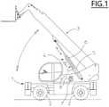
- numeral 1 indicates as a whole a self-propelled operating machine, made mobile on wheels 2, which is equipped with a manoeuvring member at the top, consisting of a telescopic hoisting arm 3, the movement of which is carried out by means of a double acting hydraulic actuator 4.
- the hydraulic actuator 4 is nothing more than a double-acting hydraulic cylinder which is hinged with its bottom side 5 to the frame of the self-propelled operating machine 4 and, with its stem, to the telescopic hoisting arm 3.
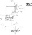
- the hydraulic actuator or double-acting hydraulic cylinder 4 is fed by a hydraulic control circuit, which is connected to a hydraulic distributor 7, from which a supply line 8 for feeding the bottom side 5 and a supply line 9 for feeding the stem side 6 originate.
- a shut-off and regulation valve 10 is provided along the supply line 8 of the bottom side 5, with the function of intercepting and regulating the flow of fluid out coming, the valve being controlled by an electronic regulation valve 11.
- This latter is operated by the signal originating from a pressure transducer 12 as a function of a pressure value measured at the stem side 6.
- the electronic regulation valve 11 is adjusted to intervene on the shut-off valve 10 in order to control and increase its opening when the pressure of the stem side 6, reported by the pressure transducer 12, reaches a preset minimum value and to open the valve up to reaching a pressure at stem side 6 having a predetermined value.
- valve 10 controlled by the electronic control valve 11
- the electronic regulation valve 11 is controlled by the value of the pressure on the stem side 6 through interposition of a pressure reducing valve 13.
- starting operation of the electronic control valve 11 is determined by its necessary adjustment, with which the minimum and maximum values that define the range of action of the "balancing" pressure have been set in advance.
- the actual pressure as reduced by the reducing valve 13, which is detected at the rod side 6 of the double-acting hydraulic cylinder 4, operates the shut-off valve 10.
- shut-off valve 10 is operated hydraulically through the interposition of the pressure reducing valve 13 and is modulated by the electronic control valve 11 which is a proportional valve.
- EVP The combination of the pressure reducing valve 13 and the electronic proportional control valve 11 is indicated by the acronym EVP, and hydraulically controls the shut-off valve 10 according to the methods described above.
- the action of the EVP system including the electronic control valve 11, thus avoids the inconvenience of possible repeated closing of the shut-off valve 10, which would cause a kind of unwanted "hopping" of the telescopic hoisting arm 3 and the load it supports, thus allowing a continuous and shock-free lowering of the piston stem of the hydraulic actuator consisting of the double acting hydraulic cylinder 4.
- Operation is simple: when the operator gives the lowering command for the telescopic hoisting arm 3, the hydraulic distributor 7 is used to send oil to the chamber at the stem side 6 of the double acting hydraulic cylinder 4.
- the electronic control valve 11 operates in such a way that the pressure on the stem side 6 starts to rise, until a certain pre-set value is reached, when the shut-off valve 10 starts to open more and more under control by the electronic regulating valve 11 and hydraulically operated by the pressure on the stem side 6 through the reducing valve 13, so gradually lowering the telescopic hoisting arm 3.
- the pressure on the stem side may decrease 6, which would cause the electronic control valve 11 to come into operation, which would command the shut-off valve 10 to reduce its opening, in order to keep the pressure on the stem side 6 within a predetermined minimum and maximum limit.
- shut-off valve 10 does not open mechanically. This means that all the safety features on the machine are not reduced or dropped.
- the movement of the telescopic hoisting arm 3 is carried out by means of two double-acting hydraulic actuators or hydraulic cylinders 4 equal to each other, which work together in conjunction with the hydraulic operation of the telescopic hoisting arm 3, both on lifting and lowering.
- Each double acting hydraulic actuator or hydraulic cylinder 4 is served by a hydraulic control circuit, which is connected to the same hydraulic distributor 7 from which, for each of them, a supply line 8 for feeding the bottom side 5 and a supply line 9 for feeding the stem side 6 originate.
- shut-off valve 10 On each of the supply lines 8 to the bottom side 5 there is a shut-off valve 10 with the function of intercepting and regulating the flow coming out of the relative bottom side 5.
- Each double acting hydraulic actuator or hydraulic cylinder 4 is fed by a hydraulic control circuit, connected to the same hydraulic distributor 7 from which, for each double-acting hydraulic actuator or hydraulic cylinder 4, the supply line 8 for feeding the bottom side 5 and supply line 9 for feeding the stem side 6 originate, as previously mentioned.
- An electronic regulation valve 11 is operated by the signal originated by a pressure transducer 12 in accordance with a pressure value detected at the stem side 6 of the double-acting hydraulic actuators or hydraulic cylinders 4.
- the electronic regulation valve 11 is adjusted to intervene on the shut-off valves 10 in order to control and increase their openings when the pressure of the stem side 6, reported by the pressure transducer 12, reaches a preset minimum value and to open the valves up to reaching pressures at stem side 6 having a predetermined value.
- valve 10 controlled by the electronic control valve 11
- the opening of valve 10, controlled by the electronic control valve 11 is reduced (when the movement stops it is completely closed), so as to maintain the pressure on the stem side (6) within a pre-established "balancing" pressure range.
- the electronic regulation valve 11 is adjusted to intervene on the shut-off valves 10 in order to control and increase their openings when the pressure of the stem side 6, reported by the pressure transducer 12, reaches a pre-set minimum threshold.
- valves 10 controlled by the electronic control valve 11 are reduced (when the movement stops they are completely closed), so as to maintain the pressure on the stem side within a pre-established "balancing" pressure range.
- the electronic regulation valve 11 is controlled by the value of the pressure on the stem side 6 through interposition of a pressure reducing valve 13.
- the electronic regulation valve 11 acts on the shut-off valves 10 so as to gradually increase their opening starting when the pressure at the stem side 6 reaches a preset minimum threshold, and to reduce, also gradually, the opening in case the pressure on the stem side is reduced, so as to maintain on the stem side a pre-set so called pressure "balancing" value.
- starting operation of the electronic control valve 11 is determined by its necessary adjustment, with which the minimum and maximum values that define the range of action of the "balancing" pressure have been set in advance.
- each shut-off valve 10 is operated by the value of the pressure at the side of the stem 6 through the interposition of a pressure reducing valve 13 and is modulated by the electronic control valve 11.
- connection 16 has been introduced between the chambers at the bottom sides 5 and a similar connection 17 has been inserted between the two chambers at the stem sides 6, which ensures stability and uniformity of pressures within the two chambers.
- the electronic regulation valve 11 operates on both shut-off valves 10 in accordance with the methods previously illustrated, carrying out gradual interventions, without abrupt movements or shocks.
- Numeral 14 indicates the driving line connecting the second shut-off valve 10, operating on the bottom side 6, to the electronic regulation valve 11 of the second double-acting hydraulic actuator or hydraulic cylinder 4.
- a parachute valve 15 is arranged and operates along the bottom side balancing line 16 of the two double-acting hydraulic actuators or hydraulic cylinders 4.
- the parachute valves 15 operate in the same way on the bottom sides of the double acting hydraulic actuators or hydraulic cylinders 4, are connected to each other by a connection 16 and have the task of preventing both chambers from emptying in the event of a breakage of a pipe.
- the modes of operation are basically those of the first illustrated embodiment characterized by the presence of a single double acting hydraulic actuator or hydraulic cylinder.
Landscapes
- Engineering & Computer Science (AREA)
- Structural Engineering (AREA)
- Transportation (AREA)
- Mechanical Engineering (AREA)
- Life Sciences & Earth Sciences (AREA)
- Geology (AREA)
- Civil Engineering (AREA)
- Chemical & Material Sciences (AREA)
- Combustion & Propulsion (AREA)
- Physics & Mathematics (AREA)
- Fluid Mechanics (AREA)
- General Engineering & Computer Science (AREA)
- Fluid-Pressure Circuits (AREA)
- Actuator (AREA)
Claims (4)
- Vorrichtung zur Regelung des Hubs von doppeltwirkenden hydraulischen Aktuatoren von der Art, die für den hydraulischen Antrieb von Manövriergliedern von Arbeitsmaschinen verwendet werden, die doppeltwirkende hydraulische Aktuatoren oder hydraulische Zylinder (4), hydraulische Steuerkreise, hydraulische Verteiler (7), Druckmesswertwandler (12) umfassen, wobei jede hydraulische Steuerschaltung ein Anlassventil (10), ein Druckminderventil (13) und ein elektronisches Regelventil (11) umfasst, wobei jeder einzelne doppeltwirkenden hydraulische Aktuator oder hydraulische Zylinder (4) von einer hydraulischen Steuerschaltung versorgt wird, die mit einem hydraulischen Verteiler (7) verbunden ist, aus dem eine Speiseleitung (8) zum Versorgen der Unterseite (5) des einzelnen doppeltwirkenden hydraulischen Aktuators oder hydraulischen Zylinders (4) hervorgeht und eine Leitung (9) zum Versorgen der Schaftseite (6) des einzelnen doppeltwirkenden hydraulischen Aktuators oder hydraulischen Zylinders (4) hervorgeht, wobei ein Anlassventil (10) an der Versorgungsseite (8) für die Unterseite (5), des einzelnen doppelt wirkenden hydraulischen Aktuators oder hydraulischen Zylinders (4), mit dem Ziel des Unterbrechens und Regelns des Ausgangsstroms angebracht ist, wobei das Anlassventil (10) durch den Druckwert an der Schaftseite (6) des einzelnen doppeltwirkenden hydraulischen Aktuators oder hydraulischen Zylinders (4), durch Zwischenschaltung eines Druckminderventils (13), hydraulisch betätigt und durch ein elektronisches Regelventil (11) moduliert wird, mit welchem es hydraulisch verbunden ist, wobei die Vorrichtung weiter Betätigungsmittel umfasst, die konfiguriert sind, um das elektronische Regelventil (11) entsprechend dem Signal zu betätigen, dass von einem Druckmesswertwandler (12) entsprechend einem Druckwert erzeugt wird, welcher an der Schaftseite (6) des einzelnen doppeltwirkenden hydraulischen Aktuators oder hydraulischen Zylinders (4) erfasst wird, wobei das elektronische Regelventil (11) betätigt wird, um auf das Anlassventil (10) einzuwirken, um dessen Öffnung beim Erreichen eines Drucks mit vordefiniertem Mindestwert an der Schaftseite (6) zu steuern und zu vergrößern und das Öffnen des Anlassventils (10) bis zum Erreichen eines Drucks mit vordefiniertem Höchstwert an der Schaftseite (6) zu vergrößern, wobei die Betätigungsmittel weiter so konfiguriert sind, dass der Öffnungsvorgang des Anlassventils (10) der vom elektrischen Regelventil (11) gesteuert wird, reduziert wird, wenn der Druck auf der Schaftseite (6) abnimmt und im Falle eines Anhaltens der Bewegung das Anlassventil (10) sich vollständig schließt, um den Druck auf der Schaftseite (6) innerhalb eines voreingestellten Druckbereichs zu halten.
- Vorrichtung gemäß Anspruch 1, dadurch gekennzeichnet, dass das elektronische Regelventil (11) ein Proportionalventil ist, dass auf das Anlassventil (10) wirkt, um dessen Öffnungsvorgang allmählich zu vergrößern, ausgehend von dem Zeitpunkt zu dem der Druck auf der Schaftseite (6) den vordefinierten Mindestwert erreicht.
- Vorrichtung zum Regeln des Hubs doppeltwirkender hydraulischer Aktuatoren, von der Art, die für den hydraulischen Antrieb von Manövriergliedern von Arbeitsmaschinen verwendet werden, Folgendes umfassend:
zwei oder mehr doppeltwirkende hydraulische Aktuatoren, oder hydraulische Zylinder (4), eine hydraulische Steuerschaltung, die Anlassventile (10), ein Druckminderventil (13) und ein elektronisches Regelventil (11) umfasst, einen hydraulischen Verteiler (7), einen Druckmesswertwandler (12), wobei die zwei oder mehr doppeltwirkenden hydraulischen Aktuatoren oder hydraulischen Zylinder (4) parallel geschaltet sind, um als ein Paar für den hydraulischen Antrieb zusammenzuwirken und jeder doppeltwirkende hydraulische Aktuator oder hydraulische Zylinder (4) von der hydraulischen Steuerschaltung versorgt wird, die mit dem hydraulischen Verteiler (7) verbunden ist, von dem Speiseleitungen (8) ausgehen, zur Versorgung jeder Unterseite (5) der zwei oder mehr doppeltwirkenden hydraulischen Aktuatoren oder hydraulischen Zylinder (4) und Leitungen (9) zur Speisung jeder Schaftseite (6) der zwei oder mehr doppeltwirkenden hydraulischen Aktuatoren oder hydraulischen Zylinder (4) ausgehen, wobei ein Anlassventil an jeder Speiseleitung (8) für die Unterseite (5) bereitgestellt ist, mit dem Ziel den Ausgangsstrom zu unterbrechen, wobei alle Anlassventile (10) mit demselben elektronischen Regelventil (11) verbunden sind, wobei die Vorrichtung weiter Betätigungsmittel umfasst, die konfiguriert sind, um das elektronische Regelventil (11) entsprechend dem Signal zu betätigen, dass vom Druckmesswertwandler (12) in Übereinstimmung mit einem entsprechenden Druckwert erzeugt wird, welches auf der Schaftseite (6) eines der zwei oder mehr hydraulischen Aktuatoren oder hydraulischen Zylinder (4) erfasst wird, um die Anlassventile (10) zu betätigen, um deren Öffnungsvorgang zu steuern und zu vergrößern, wenn ein von dem Druckmesswertwandler (12) auf der Schaftseite gemeldeter Druck einen vordefinierten Mindestwert erreicht hat und bis ein Druck auf der Schaftseite (6) einen vordefinierten Höchstwert erreicht hat, wobei alle Anlassventile (10) hydraulisch durch den Druckwert auf der Schaftseite (6) des einen oder der zwei oder mehr hydraulischen Aktuatoren oder hydraulischen Zylinder (4) betätigt werden, durch Zwischenschaltung des Druckminderventils (13) und die modulierende Wirkung des elektronischen Regelventils (11), mit dem die Anlassventile (10) hydraulisch verbunden sind, um den Druck auf der Schaftseite (6) innerhalb eines voreingestellten Druckbereichs zu halten. - Vorrichtung gemäß Anspruch 3, gekennzeichnet durch das Einschließen eines Rückschlagventils (15), dass an der Unterseite (6) jedes doppeltwirkenden hydraulischen Aktuators oder hydraulischen Zylinders (4) angebracht wird, wobei die Rückschlagventile (15) auf dieselbe Art auf die jeweiligen Unterseiten der doppeltwirkenden hydraulischen Aktuatoren oder hydraulischen Zylinder einwirken und über eine hydraulische Verbindung (16), hydraulisch direkt miteinander verbunden sind, die die Aufgabe hat, den Druck an den Unterseiten der doppeltwirkenden hydraulischen Aktuatoren oder hydraulischen Zylinder (4) auszugleichen.
Applications Claiming Priority (2)
| Application Number | Priority Date | Filing Date | Title |
|---|---|---|---|
| IT201800002731A IT201800002731A1 (it) | 2018-02-15 | 2018-02-15 | Apparecchiatura per regolarizzare la corsa di attuatori oleodinamici a doppio effetto |
| PCT/IB2019/000015 WO2019158989A1 (en) | 2018-02-15 | 2019-02-11 | Apparatus for regulating the stroke of double-acting hydraulic actuators |
Publications (2)
| Publication Number | Publication Date |
|---|---|
| EP3752739A1 EP3752739A1 (de) | 2020-12-23 |
| EP3752739B1 true EP3752739B1 (de) | 2022-03-09 |
Family
ID=62143492
Family Applications (1)
| Application Number | Title | Priority Date | Filing Date |
|---|---|---|---|
| EP19712013.2A Active EP3752739B1 (de) | 2018-02-15 | 2019-02-11 | Vorrichtung zur regelung des hubs von doppeltwirkenden hydraulischen aktuatoren |
Country Status (3)
| Country | Link |
|---|---|
| EP (1) | EP3752739B1 (de) |
| IT (1) | IT201800002731A1 (de) |
| WO (1) | WO2019158989A1 (de) |
Cited By (1)
| Publication number | Priority date | Publication date | Assignee | Title |
|---|---|---|---|---|
| IT202200017229A1 (it) * | 2022-08-11 | 2024-02-11 | Bosch Gmbh Robert | Sistema di controllo per un cilindro attuatore |
Families Citing this family (1)
| Publication number | Priority date | Publication date | Assignee | Title |
|---|---|---|---|---|
| CN114658702A (zh) * | 2022-03-30 | 2022-06-24 | 三一汽车制造有限公司 | 控制系统、臂架及作业机械 |
Family Cites Families (3)
| Publication number | Priority date | Publication date | Assignee | Title |
|---|---|---|---|---|
| WO2013169996A1 (en) * | 2012-05-10 | 2013-11-14 | Eaton Corporation | Load energy assist and horsepower management system |
| DE102012010266B4 (de) * | 2012-05-25 | 2015-02-12 | Wessel-Hydraulik Gmbh | Hydraulische Schaltungsanordnung |
| EP3104022B1 (de) * | 2015-06-12 | 2019-12-04 | National Oilwell Varco Norway AS | Verbesserungen bei der regelung hydraulischer antriebe |
-
2018
- 2018-02-15 IT IT201800002731A patent/IT201800002731A1/it unknown
-
2019
- 2019-02-11 EP EP19712013.2A patent/EP3752739B1/de active Active
- 2019-02-11 WO PCT/IB2019/000015 patent/WO2019158989A1/en not_active Ceased
Cited By (1)
| Publication number | Priority date | Publication date | Assignee | Title |
|---|---|---|---|---|
| IT202200017229A1 (it) * | 2022-08-11 | 2024-02-11 | Bosch Gmbh Robert | Sistema di controllo per un cilindro attuatore |
Also Published As
| Publication number | Publication date |
|---|---|
| WO2019158989A1 (en) | 2019-08-22 |
| IT201800002731A1 (it) | 2019-08-15 |
| EP3752739A1 (de) | 2020-12-23 |
Similar Documents
| Publication | Publication Date | Title |
|---|---|---|
| US10865765B2 (en) | Device for supplying and modifying a cylinder cubic capacity of a hydraulic motor | |
| US9206821B2 (en) | Hydraulic switching mechanism for mobile hydraulics, mobile hydraulic machine and valve unit | |
| US8671824B2 (en) | Hydraulic control system | |
| US9394922B2 (en) | Hydraulic control circuit with regeneration valve | |
| US20100186401A1 (en) | Method and hydraulic control system for supplying pressure medium to at least one hydraulic consumer | |
| KR20010071622A (ko) | 모빌 작업 기계 | |
| US6389953B1 (en) | Hydraulic leveling control system for a loader type vehicle | |
| EP3752739B1 (de) | Vorrichtung zur regelung des hubs von doppeltwirkenden hydraulischen aktuatoren | |
| US10773629B2 (en) | Construction machine | |
| EP3312436B1 (de) | Anti-rohrbruch apparatus | |
| US12404878B2 (en) | Actuating device for at least one fluidically drivable consumer | |
| EP2786959B1 (de) | Kavitationsschutzvorrichtung für einen Hydraulikzylinder | |
| EP3228580B1 (de) | Steuerungsvorrichtung für einen aktuator | |
| US3297183A (en) | Hydraulic self-leveling device for a front mounted bucket type material loader | |
| US4433612A (en) | Safety control device for protecting hydraulically held loads against uncontrolled pressure overloading | |
| US10145086B2 (en) | Apparatus for blocking and for adjusting a pressure | |
| EP1932797A1 (de) | Hebevorrichtung | |
| US20010015129A1 (en) | Hydraulic leveling control system for a loader type vehicle | |
| CA1120826A (en) | Control valve for working machine | |
| EP0910748B1 (de) | Verteiler für einen hydraulischen heber, welcher hinsichtlich position und aufgebrachter kraft steuerbar ist, zum einsatz in traktoren und landwirtschaftliche maschinen | |
| EP4428376A1 (de) | Vorrichtung zur steuerung des senkens eines hydraulischen zylinders, insbesondere zur steuerung des senkens eines bedienungsarms | |
| EP1733996B1 (de) | Hydraulische Vorrichtung zum Heben und Senken eines an einer Arbeitsmaschine schwenkbaren Arms | |
| EP3599383B1 (de) | Steuerungsvorrichtung für aktuator | |
| EP2196682A1 (de) | Hydraulische Steuervorrichtung für einen Stellantrieb eines Arbeitsfahrzeugs | |
| US5239912A (en) | Hydraulic circuit to limit static and/or dynamic pressure loads |
Legal Events
| Date | Code | Title | Description |
|---|---|---|---|
| STAA | Information on the status of an ep patent application or granted ep patent |
Free format text: STATUS: UNKNOWN |
|
| STAA | Information on the status of an ep patent application or granted ep patent |
Free format text: STATUS: THE INTERNATIONAL PUBLICATION HAS BEEN MADE |
|
| PUAI | Public reference made under article 153(3) epc to a published international application that has entered the european phase |
Free format text: ORIGINAL CODE: 0009012 |
|
| STAA | Information on the status of an ep patent application or granted ep patent |
Free format text: STATUS: REQUEST FOR EXAMINATION WAS MADE |
|
| 17P | Request for examination filed |
Effective date: 20200819 |
|
| AK | Designated contracting states |
Kind code of ref document: A1 Designated state(s): AL AT BE BG CH CY CZ DE DK EE ES FI FR GB GR HR HU IE IS IT LI LT LU LV MC MK MT NL NO PL PT RO RS SE SI SK SM TR |
|
| AX | Request for extension of the european patent |
Extension state: BA ME |
|
| DAV | Request for validation of the european patent (deleted) | ||
| DAX | Request for extension of the european patent (deleted) | ||
| GRAP | Despatch of communication of intention to grant a patent |
Free format text: ORIGINAL CODE: EPIDOSNIGR1 |
|
| STAA | Information on the status of an ep patent application or granted ep patent |
Free format text: STATUS: GRANT OF PATENT IS INTENDED |
|
| INTG | Intention to grant announced |
Effective date: 20211014 |
|
| GRAS | Grant fee paid |
Free format text: ORIGINAL CODE: EPIDOSNIGR3 |
|
| GRAA | (expected) grant |
Free format text: ORIGINAL CODE: 0009210 |
|
| STAA | Information on the status of an ep patent application or granted ep patent |
Free format text: STATUS: THE PATENT HAS BEEN GRANTED |
|
| AK | Designated contracting states |
Kind code of ref document: B1 Designated state(s): AL AT BE BG CH CY CZ DE DK EE ES FI FR GB GR HR HU IE IS IT LI LT LU LV MC MK MT NL NO PL PT RO RS SE SI SK SM TR |
|
| REG | Reference to a national code |
Ref country code: CH Ref legal event code: EP Ref country code: AT Ref legal event code: REF Ref document number: 1474365 Country of ref document: AT Kind code of ref document: T Effective date: 20220315 |
|
| REG | Reference to a national code |
Ref country code: IE Ref legal event code: FG4D |
|
| REG | Reference to a national code |
Ref country code: DE Ref legal event code: R096 Ref document number: 602019012384 Country of ref document: DE |
|
| REG | Reference to a national code |
Ref country code: NL Ref legal event code: FP |
|
| REG | Reference to a national code |
Ref country code: LT Ref legal event code: MG9D |
|
| PG25 | Lapsed in a contracting state [announced via postgrant information from national office to epo] |
Ref country code: SE Free format text: LAPSE BECAUSE OF FAILURE TO SUBMIT A TRANSLATION OF THE DESCRIPTION OR TO PAY THE FEE WITHIN THE PRESCRIBED TIME-LIMIT Effective date: 20220309 Ref country code: RS Free format text: LAPSE BECAUSE OF FAILURE TO SUBMIT A TRANSLATION OF THE DESCRIPTION OR TO PAY THE FEE WITHIN THE PRESCRIBED TIME-LIMIT Effective date: 20220309 Ref country code: NO Free format text: LAPSE BECAUSE OF FAILURE TO SUBMIT A TRANSLATION OF THE DESCRIPTION OR TO PAY THE FEE WITHIN THE PRESCRIBED TIME-LIMIT Effective date: 20220609 Ref country code: LT Free format text: LAPSE BECAUSE OF FAILURE TO SUBMIT A TRANSLATION OF THE DESCRIPTION OR TO PAY THE FEE WITHIN THE PRESCRIBED TIME-LIMIT Effective date: 20220309 Ref country code: HR Free format text: LAPSE BECAUSE OF FAILURE TO SUBMIT A TRANSLATION OF THE DESCRIPTION OR TO PAY THE FEE WITHIN THE PRESCRIBED TIME-LIMIT Effective date: 20220309 Ref country code: BG Free format text: LAPSE BECAUSE OF FAILURE TO SUBMIT A TRANSLATION OF THE DESCRIPTION OR TO PAY THE FEE WITHIN THE PRESCRIBED TIME-LIMIT Effective date: 20220609 |
|
| REG | Reference to a national code |
Ref country code: AT Ref legal event code: MK05 Ref document number: 1474365 Country of ref document: AT Kind code of ref document: T Effective date: 20220309 |
|
| PG25 | Lapsed in a contracting state [announced via postgrant information from national office to epo] |
Ref country code: LV Free format text: LAPSE BECAUSE OF FAILURE TO SUBMIT A TRANSLATION OF THE DESCRIPTION OR TO PAY THE FEE WITHIN THE PRESCRIBED TIME-LIMIT Effective date: 20220309 Ref country code: GR Free format text: LAPSE BECAUSE OF FAILURE TO SUBMIT A TRANSLATION OF THE DESCRIPTION OR TO PAY THE FEE WITHIN THE PRESCRIBED TIME-LIMIT Effective date: 20220610 Ref country code: FI Free format text: LAPSE BECAUSE OF FAILURE TO SUBMIT A TRANSLATION OF THE DESCRIPTION OR TO PAY THE FEE WITHIN THE PRESCRIBED TIME-LIMIT Effective date: 20220309 |
|
| PG25 | Lapsed in a contracting state [announced via postgrant information from national office to epo] |
Ref country code: SM Free format text: LAPSE BECAUSE OF FAILURE TO SUBMIT A TRANSLATION OF THE DESCRIPTION OR TO PAY THE FEE WITHIN THE PRESCRIBED TIME-LIMIT Effective date: 20220309 Ref country code: SK Free format text: LAPSE BECAUSE OF FAILURE TO SUBMIT A TRANSLATION OF THE DESCRIPTION OR TO PAY THE FEE WITHIN THE PRESCRIBED TIME-LIMIT Effective date: 20220309 Ref country code: RO Free format text: LAPSE BECAUSE OF FAILURE TO SUBMIT A TRANSLATION OF THE DESCRIPTION OR TO PAY THE FEE WITHIN THE PRESCRIBED TIME-LIMIT Effective date: 20220309 Ref country code: PT Free format text: LAPSE BECAUSE OF FAILURE TO SUBMIT A TRANSLATION OF THE DESCRIPTION OR TO PAY THE FEE WITHIN THE PRESCRIBED TIME-LIMIT Effective date: 20220711 Ref country code: ES Free format text: LAPSE BECAUSE OF FAILURE TO SUBMIT A TRANSLATION OF THE DESCRIPTION OR TO PAY THE FEE WITHIN THE PRESCRIBED TIME-LIMIT Effective date: 20220309 Ref country code: EE Free format text: LAPSE BECAUSE OF FAILURE TO SUBMIT A TRANSLATION OF THE DESCRIPTION OR TO PAY THE FEE WITHIN THE PRESCRIBED TIME-LIMIT Effective date: 20220309 Ref country code: CZ Free format text: LAPSE BECAUSE OF FAILURE TO SUBMIT A TRANSLATION OF THE DESCRIPTION OR TO PAY THE FEE WITHIN THE PRESCRIBED TIME-LIMIT Effective date: 20220309 Ref country code: AT Free format text: LAPSE BECAUSE OF FAILURE TO SUBMIT A TRANSLATION OF THE DESCRIPTION OR TO PAY THE FEE WITHIN THE PRESCRIBED TIME-LIMIT Effective date: 20220309 |
|
| PG25 | Lapsed in a contracting state [announced via postgrant information from national office to epo] |
Ref country code: PL Free format text: LAPSE BECAUSE OF FAILURE TO SUBMIT A TRANSLATION OF THE DESCRIPTION OR TO PAY THE FEE WITHIN THE PRESCRIBED TIME-LIMIT Effective date: 20220309 Ref country code: IS Free format text: LAPSE BECAUSE OF FAILURE TO SUBMIT A TRANSLATION OF THE DESCRIPTION OR TO PAY THE FEE WITHIN THE PRESCRIBED TIME-LIMIT Effective date: 20220709 Ref country code: AL Free format text: LAPSE BECAUSE OF FAILURE TO SUBMIT A TRANSLATION OF THE DESCRIPTION OR TO PAY THE FEE WITHIN THE PRESCRIBED TIME-LIMIT Effective date: 20220309 |
|
| REG | Reference to a national code |
Ref country code: DE Ref legal event code: R097 Ref document number: 602019012384 Country of ref document: DE |
|
| PLBE | No opposition filed within time limit |
Free format text: ORIGINAL CODE: 0009261 |
|
| STAA | Information on the status of an ep patent application or granted ep patent |
Free format text: STATUS: NO OPPOSITION FILED WITHIN TIME LIMIT |
|
| PG25 | Lapsed in a contracting state [announced via postgrant information from national office to epo] |
Ref country code: DK Free format text: LAPSE BECAUSE OF FAILURE TO SUBMIT A TRANSLATION OF THE DESCRIPTION OR TO PAY THE FEE WITHIN THE PRESCRIBED TIME-LIMIT Effective date: 20220309 |
|
| 26N | No opposition filed |
Effective date: 20221212 |
|
| PG25 | Lapsed in a contracting state [announced via postgrant information from national office to epo] |
Ref country code: SI Free format text: LAPSE BECAUSE OF FAILURE TO SUBMIT A TRANSLATION OF THE DESCRIPTION OR TO PAY THE FEE WITHIN THE PRESCRIBED TIME-LIMIT Effective date: 20220309 |
|
| P01 | Opt-out of the competence of the unified patent court (upc) registered |
Effective date: 20230527 |
|
| PG25 | Lapsed in a contracting state [announced via postgrant information from national office to epo] |
Ref country code: MC Free format text: LAPSE BECAUSE OF FAILURE TO SUBMIT A TRANSLATION OF THE DESCRIPTION OR TO PAY THE FEE WITHIN THE PRESCRIBED TIME-LIMIT Effective date: 20220309 |
|
| REG | Reference to a national code |
Ref country code: CH Ref legal event code: PL |
|
| REG | Reference to a national code |
Ref country code: BE Ref legal event code: MM Effective date: 20230228 |
|
| GBPC | Gb: european patent ceased through non-payment of renewal fee |
Effective date: 20230211 |
|
| PG25 | Lapsed in a contracting state [announced via postgrant information from national office to epo] |
Ref country code: LU Free format text: LAPSE BECAUSE OF NON-PAYMENT OF DUE FEES Effective date: 20230211 Ref country code: LI Free format text: LAPSE BECAUSE OF NON-PAYMENT OF DUE FEES Effective date: 20230228 Ref country code: CH Free format text: LAPSE BECAUSE OF NON-PAYMENT OF DUE FEES Effective date: 20230228 |
|
| REG | Reference to a national code |
Ref country code: IE Ref legal event code: MM4A |
|
| PG25 | Lapsed in a contracting state [announced via postgrant information from national office to epo] |
Ref country code: GB Free format text: LAPSE BECAUSE OF NON-PAYMENT OF DUE FEES Effective date: 20230211 |
|
| PG25 | Lapsed in a contracting state [announced via postgrant information from national office to epo] |
Ref country code: IE Free format text: LAPSE BECAUSE OF NON-PAYMENT OF DUE FEES Effective date: 20230211 Ref country code: GB Free format text: LAPSE BECAUSE OF NON-PAYMENT OF DUE FEES Effective date: 20230211 |
|
| PG25 | Lapsed in a contracting state [announced via postgrant information from national office to epo] |
Ref country code: BE Free format text: LAPSE BECAUSE OF NON-PAYMENT OF DUE FEES Effective date: 20230228 |
|
| PGFP | Annual fee paid to national office [announced via postgrant information from national office to epo] |
Ref country code: NL Payment date: 20250207 Year of fee payment: 7 |
|
| PGFP | Annual fee paid to national office [announced via postgrant information from national office to epo] |
Ref country code: DE Payment date: 20250207 Year of fee payment: 7 |
|
| PGFP | Annual fee paid to national office [announced via postgrant information from national office to epo] |
Ref country code: FR Payment date: 20250211 Year of fee payment: 7 |
|
| PGFP | Annual fee paid to national office [announced via postgrant information from national office to epo] |
Ref country code: IT Payment date: 20250120 Year of fee payment: 7 |
|
| PG25 | Lapsed in a contracting state [announced via postgrant information from national office to epo] |
Ref country code: CY Free format text: LAPSE BECAUSE OF FAILURE TO SUBMIT A TRANSLATION OF THE DESCRIPTION OR TO PAY THE FEE WITHIN THE PRESCRIBED TIME-LIMIT; INVALID AB INITIO Effective date: 20190211 |
|
| PG25 | Lapsed in a contracting state [announced via postgrant information from national office to epo] |
Ref country code: HU Free format text: LAPSE BECAUSE OF FAILURE TO SUBMIT A TRANSLATION OF THE DESCRIPTION OR TO PAY THE FEE WITHIN THE PRESCRIBED TIME-LIMIT; INVALID AB INITIO Effective date: 20190211 |
|
| PG25 | Lapsed in a contracting state [announced via postgrant information from national office to epo] |
Ref country code: TR Free format text: LAPSE BECAUSE OF FAILURE TO SUBMIT A TRANSLATION OF THE DESCRIPTION OR TO PAY THE FEE WITHIN THE PRESCRIBED TIME-LIMIT Effective date: 20220309 |