EP3752702B1 - Systems and methods for underground pipe installation - Google Patents
Systems and methods for underground pipe installation Download PDFInfo
- Publication number
- EP3752702B1 EP3752702B1 EP19707216.8A EP19707216A EP3752702B1 EP 3752702 B1 EP3752702 B1 EP 3752702B1 EP 19707216 A EP19707216 A EP 19707216A EP 3752702 B1 EP3752702 B1 EP 3752702B1
- Authority
- EP
- European Patent Office
- Prior art keywords
- pipe
- section
- clearing
- soil
- frame
- Prior art date
- Legal status (The legal status is an assumption and is not a legal conclusion. Google has not performed a legal analysis and makes no representation as to the accuracy of the status listed.)
- Active
Links
Images


Classifications
-
- F—MECHANICAL ENGINEERING; LIGHTING; HEATING; WEAPONS; BLASTING
- F16—ENGINEERING ELEMENTS AND UNITS; GENERAL MEASURES FOR PRODUCING AND MAINTAINING EFFECTIVE FUNCTIONING OF MACHINES OR INSTALLATIONS; THERMAL INSULATION IN GENERAL
- F16L—PIPES; JOINTS OR FITTINGS FOR PIPES; SUPPORTS FOR PIPES, CABLES OR PROTECTIVE TUBING; MEANS FOR THERMAL INSULATION IN GENERAL
- F16L1/00—Laying or reclaiming pipes; Repairing or joining pipes on or under water
- F16L1/024—Laying or reclaiming pipes on land, e.g. above the ground
- F16L1/028—Laying or reclaiming pipes on land, e.g. above the ground in the ground
- F16L1/036—Laying or reclaiming pipes on land, e.g. above the ground in the ground the pipes being composed of sections of short length
-
- E—FIXED CONSTRUCTIONS
- E21—EARTH OR ROCK DRILLING; MINING
- E21B—EARTH OR ROCK DRILLING; OBTAINING OIL, GAS, WATER, SOLUBLE OR MELTABLE MATERIALS OR A SLURRY OF MINERALS FROM WELLS
- E21B1/00—Percussion drilling
- E21B1/02—Surface drives for drop hammers or percussion drilling, e.g. with a cable
-
- E—FIXED CONSTRUCTIONS
- E21—EARTH OR ROCK DRILLING; MINING
- E21B—EARTH OR ROCK DRILLING; OBTAINING OIL, GAS, WATER, SOLUBLE OR MELTABLE MATERIALS OR A SLURRY OF MINERALS FROM WELLS
- E21B19/00—Handling rods, casings, tubes or the like outside the borehole, e.g. in the derrick; Apparatus for feeding the rods or cables
- E21B19/08—Apparatus for feeding the rods or cables; Apparatus for increasing or decreasing the pressure on the drilling tool; Apparatus for counterbalancing the weight of the rods
- E21B19/086—Apparatus for feeding the rods or cables; Apparatus for increasing or decreasing the pressure on the drilling tool; Apparatus for counterbalancing the weight of the rods with a fluid-actuated cylinder
-
- E—FIXED CONSTRUCTIONS
- E21—EARTH OR ROCK DRILLING; MINING
- E21B—EARTH OR ROCK DRILLING; OBTAINING OIL, GAS, WATER, SOLUBLE OR MELTABLE MATERIALS OR A SLURRY OF MINERALS FROM WELLS
- E21B7/00—Special methods or apparatus for drilling
- E21B7/04—Directional drilling
- E21B7/046—Directional drilling horizontal drilling
-
- E—FIXED CONSTRUCTIONS
- E21—EARTH OR ROCK DRILLING; MINING
- E21B—EARTH OR ROCK DRILLING; OBTAINING OIL, GAS, WATER, SOLUBLE OR MELTABLE MATERIALS OR A SLURRY OF MINERALS FROM WELLS
- E21B7/00—Special methods or apparatus for drilling
- E21B7/20—Driving or forcing casings or pipes into boreholes, e.g. sinking; Simultaneously drilling and casing boreholes
- E21B7/201—Driving or forcing casings or pipes into boreholes, e.g. sinking; Simultaneously drilling and casing boreholes with helical conveying means
-
- E—FIXED CONSTRUCTIONS
- E21—EARTH OR ROCK DRILLING; MINING
- E21D—SHAFTS; TUNNELS; GALLERIES; LARGE UNDERGROUND CHAMBERS
- E21D9/00—Tunnels or galleries, with or without linings; Methods or apparatus for making thereof; Layout of tunnels or galleries
- E21D9/005—Tunnels or galleries, with or without linings; Methods or apparatus for making thereof; Layout of tunnels or galleries by forcing prefabricated elements through the ground, e.g. by pushing lining from an access pit
-
- E—FIXED CONSTRUCTIONS
- E21—EARTH OR ROCK DRILLING; MINING
- E21D—SHAFTS; TUNNELS; GALLERIES; LARGE UNDERGROUND CHAMBERS
- E21D9/00—Tunnels or galleries, with or without linings; Methods or apparatus for making thereof; Layout of tunnels or galleries
- E21D9/06—Making by using a driving shield, i.e. advanced by pushing means bearing against the already placed lining
Definitions
- the invention relates generally to systems and methods for installing underground sections of pipe, including pipeline, gas mains, water and sewer lines, utility conduits and other utilities. More specifically, the invention relates to trenchless underground pipe installation, for example using tools and methods that are suitable to install new pipes using one or more of a hydraulic jacking force, pneumatic percussive impacts, and a dirt-extraction process of soil coming inside the pipe during installation.
- the machine comprises a base that includes spaced track members, which are disposed in a trench adjacent to the hill to be bored.
- the machine also includes a frame mounted for movement along the track means, and such carriage supports a power train for rotating connected sections of auger shafts, which comprise a progressively extendable boring auger (See FIG. 1 ).
- the frame supports a pusher ring for driving sections of casings into the bored hole, and an associated pushing cylinder is provided for advancing and retracting the frame and pusher ring along the track.
- trenchless methods are related to micro-tunneling machines.
- Such systems involve a whole family of machines with some variations among them. Many of the variations differ on how the soil is excavated and how the spoils are transported to the surface of the jacking shaft. In general terms, they include a boring shield that is pushed forward by the product pipes behind it, which are being jacked by large and robust hydraulic jacks in the launch pit. As these micro-tunnel boring machines move forward through the ground, the soil is removed by typically mixing it with a fluid, to then pump the mixture out of the tunnel into a separation plant, wherein the solids are separated from the fluids.
- a percussive pneumatic hammer is used to drive the pipe horizontally or at an angle into the ground.
- the hammer's housing is attached to the end of the pipe by means of a suitable fitting and is sometimes further secured by cables.
- a piston-actuated ram strikes a plate inside the housing and the percussive force is transmitted to the end of the pipe through the housing, thereby causing the pipe to advance into the ground.
- Pneumatic rammers are characterized by producing several blows per minute, delivering low to medium energy on each blow.
- a typical small pneumatic hammer offers 0.17 kJ of energy and delivers 580 blows per minute, weighing less than 10 kg.
- a typical large hammer has 40 kJ of energy, weighs 12 metric tons and delivers 180 blows per minute.
- Hydraulic (rather than pneumatic) hammers are often used in vertical drilling. This type of large hammers generally operates at fewer strokes per minute but delivers much more per blow. In this case, the strike piston extends outside the hammer housing to strike the casing. Typically, one hydraulic hammer weighs 4 metric tons, delivers 65 blows per minute at 30 kJ, while a 242 metric ton hammer delivers 2300 kJ at 30 blows per minute. In vertical drilling, the hammer housing is maintained in contact against the casing principally by means of gravity. Even if they are not commonly used for horizontal pipe ramming, they are an alternative when installing large casing diameters.
- one common problem with percussive pipe ramming methods is that the soil-clearing process cannot be done at the same time with the installation process, leading to a reduction in overall productivity.
- Another common problem is the need of relatively high energy quantities (big hammers) to install the pipes or casings since a considerable part of the energy of each impact is lost.
- One relevant part of the energy is absorbed by the natural steel pipe elasticity, and the pipe's external and internal skin friction (from the soil coming inside) dissipates another important part of the energy.
- unstable soils e.g., cobble
- sandy or granular soils with presence of ground water or highly heterogeneous soils along the drive.
- a hydraulic jacking frame compresses and pushes the steel pipes against the ground with a constant force, while percussion impacts coming from a pneumatic rammer generate additional penetration force to move forward the pipes into the ground.
- the open-ended pipe in the front lets the soil come inside it, while an independent linear displaceable soil-clearing system progressively removes the dirt while the installation progresses, reducing the total moving mass during the installation, and consequently augmenting the effectiveness of the impacts.
- the cutting edge allows the soil to enter into the pipe with low requirements of penetration force, unlike in the case of apparatus with rotational cutting heads in front of the first pipe.
- the impact force applied is maximized since constant hydraulic force minimizes energy losses caused by the pipe bounce back (due to the natural pipe's elasticity), while adding force to overcome the skin friction of the pipe or casing.
- the pneumatic rammer generates lower energy peaks compared to a hydraulic hammer, at a higher frequency (e.g., from 160 to 580 blows per minute), and these lower energy peaks allow applying a higher static force to the pipes without the need to use thicker steel pipes.
- the main jacking frame comprises hydraulic cylinders acting on a rail-mounted pusher plate in which the percussive pneumatic rammer is firmly attached by means of a suitable fitting.
- the pusher plate works as a device for combining the impacts and the static force in order to transform that energy into penetration force for the pipes in front of it, while maintaining the pipe at the desired alignment.
- the fitting of the hydraulic rammer is slightly eccentric with respect to the pipe's centerline in order to let the clearing rods (which are aligned to the centerline) pass through a window in the pusher plate to clear the dirt inside the pipes.
- the soil-clearing system includes clearing rods, at least one auger section, and a linear displaceable frame carrying a hydraulic motor on it.
- This frame is mounted on the same main jacking system's rails but with an independent set of hydraulic actuators for going forward and backward along those rails or tracks.
- the dirt-extraction system of this invention differs from existing auger-based methods since, instead of dragging the dirt using only the rotation of a continuous auger set, the system uses the rotation (while going forward) of a few equally-distanced auger segments only to capture the soil inside the pipe like the analogical case of a wine-bottle opener capturing a bottle's cork.
- this soil-clearing system can be substituted by a continuous auger driven by a bigger hydraulic motor fixed at the main jacking frame, like a standard auger boring machine.
- This last configuration can require more torque and may need to replace the whole auger set every time the diameter of the pipe changes, instead of changing just a few auger segments.
- the soil clearing system can include at least one clearing rod with one auger section, or alternatively, just one auger section attached directly to the hydraulic motor.
- Another feature of the present invention is the power optimization capability in which the independent linear displaceable soil-clearing system is used for generating a supplementary hydraulic jacking force, only when extra pushing force is needed. That is, pushing, with their own hydraulic cylinders, the main jacking frame to increase the total pushing force in order to overcome obstacles, high skin friction of long drives, or hard soil conditions. The extraction of the excavated material is temporarily suspended when the clearing-soil system is used for pushing the jacking frame.
- the invention features a system for installing pipe underground.
- the system includes a pneumatic rammer configured to provide a percussive force to a section of pipe.
- the system also includes a main jacking frame coupled to the pneumatic rammer, the main jacking frame including a surface for contacting the section of pipe.
- the system also includes one or more hydraulic jacks coupled to the main jacking frame and configured to provide a hydraulic force to the section of pipe.
- the system also includes a set of tracks coupled to the main jacking frame, the set of tracks permitting the main jacking frame to slide in a longitudinal direction.
- the system further includes a soil-clearing system having a base frame coupled to the set of tracks.
- the soil-clearing system is configured to extract dirt from inside the section of pipe during underground installation of the section of pipe.
- the base frame is slideable over the set of tracks independent of the main jacking frame.
- the soil-clearing system includes a rod-auger assembly driven by a hydraulic motor or another rotating actuator to drag dirt during operation.
- the main jacking frame includes a pusher plate having at least one window to permit passage of dirt by the soil-clearing system.
- the soil-clearing system includes at least one clearing rod, at least one auger section attached to the clearing rod, and an axially displaceable rail-mounted frame attached to the clearing rod, the rail-mounted frame carrying a hydraulic motor.
- the rail-mounted frame moves forward and backward along the longitudinal direction by means of at least one hydraulic cylinder acting between the rail-mounted frame and a locking system.
- the at least one clearing rod, the at least one auger section, and the axially displaceable rail-mounted frame are configured to extract dirt from sequential sections of pipe.
- the pneumatic rammer is a high frequency rammer from 160 to 580 blows per minute.
- the section of pipe is steel.
- the steel pipe acts as a steel casing for carrying other pipes inside.
- the section of pipe has a diameter of 1.8 meters (72 inches) or less.
- the invention features a method for installing pipe underground.
- the method includes compressing, by a main jacking frame coupled to a set of tracks and assisted by at least one hydraulic cylinder, a section of pipe against a ground surface.
- the method also includes generating, by a pneumatic rammer attached to the main jacking frame, a percussive impact for advancing the section of pipe into the ground.
- the method also includes pushing, by the jacking frame and the pneumatic rammer, the pipes into the ground.
- the method further includes extracting, using a soil clearing system coupled to the set of tracks, dirt from inside the section of pipe during installation of the section of pipe, the soil clearing system moveable with respect to the main jacking frame.
- the main jacking frame includes a pusher plate having at least one window to permit passage of dirt by the soil-clearing system.
- the method further includes employing a hydraulic force to pre-compress the section of pipe to counteract an elasticity of the section of pipe to promote efficient energy transmission from the pneumatic rammer through the section of pipe.
- a constant force is applied against the ground by the jacking frame.
- the method further includes, after the section of pipe is installed underground, joining one or more additional sections of pipe to the section of pipe to form an underground tunnel between an entry point under the ground surface and a target pit.
- the pneumatic rammer is a high frequency rammer from 160 to 580 blows per minute.
- the soil-clearing system includes at least one clearing rod, at least one auger section attached to the clearing rod, and an axially displaceable rail-mounted frame attached to the clearing rod, the rail-mounted frame including a hydraulic motor.
- the rail-mounted frame moves forward and backward along the longitudinal direction by means of at least one hydraulic cylinder acting between the rail-mounted frame and a locking system.
- the soil-clearing system includes at least two clearing rods, each clearing rod having at least one auger section, the axially displaceable rail-mounted frame configured to extract dirt sequentially in a coordinated movement of the at least two clearing rods and auger sections.
- the soil-clearing system includes an uninterrupted auger assembly driven by a hydraulic motor to drag dirt during operation.
- the invention features a system for clearing soil from a section of pipe during underground installation.
- the system includes a main jacking frame including a surface for contacting the section of pipe.
- the system also includes a set of tracks coupled to the main jacking frame, the set of tracks permitting the main jacking frame to slide along a longitudinal direction.
- the system also includes a soil-clearing system having a base frame coupled to the set of tracks, the soil-clearing system configured to extract dirt from inside the section of pipe during underground installation of the section of pipe, the soil-clearing system moveable along the longitudinal direction independent of the main jacking frame and including at least one auger mounted in a frame coupled to the set of tracks that can move forward and backward along the longitudinal direction independently of the main jacking frame.
- the invention features a method for clearing soil from a section of pipe during underground installation.
- the method includes extracting, using a soil clearing system coupled to a set of tracks, dirt from inside the section of pipe during installation of the section of pipe, the soil clearing system slideable over the set of tracks.
- the soil-clearing system includes at least one clearing rod, at least one auger section attached to the clearing rod, and an axially displaceable rail-mounted frame attached to the clearing rod, the rail-mounted frame including a hydraulic motor.
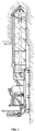
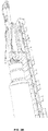
- the rammer 10 is used to generate a cyclical force (e.g., a series of percussive impacts) to a riel-mounted main jacking frame 12.
- the rammer 10 may be driven percussively by a pneumatic hammer or other high frequency driving apparatus, acting on the main jacking frame 12 using any suitable fitting device (not shown).
- the rammer 10 can be of the type manufactured by Hammerhead Trenchless Equipment, Model No. 12-(300)-AR. Other models of rammers could also be used.
- the jacking frame is assisted by a set of hydraulic jacks 14, which add hydraulic pushing force to the main jacking frame 12.
- the main jacking frame 12 has a surface for contacting the casing 16 and transmits the percussive force and the hydraulic force to the casing 16.
- the casing section 16 may be substituted by any product pipe able to resist and transmit the impact force generated by the rammer 10.
- the main jacking frame 12 is coupled and slides over the modular main tracks 18 which are assembled together to reach the desired stroke for the linear displacement of the main jacking frame 12, depending on the available space in the entry pit 20.
- a soil-clearing system 22 e.g., an independent, displaceable soil-clearing system
- the soil-clearing system 22 brings the excavated material to the entry pit 20 by dragging it through an open section or window in the main jacking frame 12, letting the material being collected into an optional bucket cart 24 attached to the main jacking frame 12. Once the bucket cart 24 is full of material, it can be removed from the main jacking frame 12 in order to dispose the material in a designated place on the surface. Alternatively, the spoils can be dropped in the entry pit without that optional bucket cart 24 , to be collected later on manually or by means of an excavator machine.
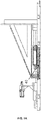
- FIG. 4B shows how the main tracks assembly are leaning on a support wall 26 for counteracting the reaction forces generated when jacking the casing sections 16 into the ground.
- Other types of anchoring methods could also be used to maintain the main tracks 18 fixed to the entry pit 20.
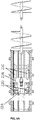
- FIG. 5A and FIG. 5B expose the details of the soil-clearing system 22 which is a rail-mounted assembly of other subsystems explained as follows.
- a base frame 22A is used to support the whole soil-clearing system and it is able to slide over the main tracks 18 without interfering with the path of the jacking frame 12.
- the base frame 22A has short tracks attached in order to let slide over it top frame 22B.
- the relative linear displacement between base frame 22A and top frame 22B is generated by means of another set of supplementary hydraulic jacks 22C.
- a supplementary self-anchoring system 22D is shown in order to avoid relative movement between the base frame 22A and the main tracks 18.
- the top frame 22B also includes a housing and a rotor mounted on taper roller bearings for supporting radial and axial forces.
- the rotor of the top frame 22B is attached to the shaft of a hydraulic motor 22E, which provides rotation to the soil-clearing system.
- the torque provided by hydraulic motor 22E and the push/pull force are transmitted through the detachable clearing rods 28.
- Each clearing rod 28 is provided with a male and a female connection and a hole in each connection in order to accommodate a pin 38 for locking the clearing rod 28 to the next one.
- a set of supplementary augers 34 can be progressively added to the clearing rods 28 assembly during the casing installation process. For drilling the compacted soil coming inside the first casing section 16, an auger bit 36 is installed in front of the first clearing rod 28.
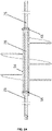
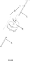
- FIG. 6A shows a cross section of a clearing rod 28 - supplementary auger 34 assembly.
- the supplementary augers 34 have an annular space in order to accommodate inside it the clearing rod 28. Then the two pieces are joined together by the means of threaded pins 38. Other type locking methods could also be used to fix the two parts together.
- FIG. 6B exemplifies how the clearing rods 28 and the supplementary auger 34 are assembled using the threaded pins 38.
- FIG. 7A shows a partial cross section of the main self-anchoring system 40 of the main jacking frame 12, in which the main hydraulic jacks 14 lean on to push or retract the main jacking frame 12.
- This component of the invention can be substituted with any anchoring systems such as manual locking levers, hydraulic locks, electric solenoids, or another locking component to provide a pushing point for the main hydraulic jacks 14.
- FIG. 7B also exposes a cross section of a detailed view for the supplementary self-anchoring system 22D explained above.
- the operation mode is based on releasing the lock (also called dogs) from the main tracks 18, and then retract or expand the hydraulic jacks in order to shift to another anchoring point.
- Another feature of this invention is the possibility to increase hydraulic power used to push the main jacking frame 12 when needed by relying on the supplementary hydraulic jacks 22C of the soil-clearing system 22. This is possible since the soil-clearing system 22 can move independently from the main jacking system.
Landscapes
- Engineering & Computer Science (AREA)
- Mining & Mineral Resources (AREA)
- Geology (AREA)
- Life Sciences & Earth Sciences (AREA)
- General Life Sciences & Earth Sciences (AREA)
- Environmental & Geological Engineering (AREA)
- Geochemistry & Mineralogy (AREA)
- Fluid Mechanics (AREA)
- Physics & Mathematics (AREA)
- Mechanical Engineering (AREA)
- General Engineering & Computer Science (AREA)
- Earth Drilling (AREA)
- Excavating Of Shafts Or Tunnels (AREA)
- Laying Of Electric Cables Or Lines Outside (AREA)
- Rigid Pipes And Flexible Pipes (AREA)
- Domestic Plumbing Installations (AREA)
Applications Claiming Priority (2)
| Application Number | Priority Date | Filing Date | Title |
|---|---|---|---|
| US201862629865P | 2018-02-13 | 2018-02-13 | |
| PCT/US2019/017198 WO2019160757A1 (en) | 2018-02-13 | 2019-02-08 | Systems and methods for underground pipe installation |
Publications (2)
| Publication Number | Publication Date |
|---|---|
| EP3752702A1 EP3752702A1 (en) | 2020-12-23 |
| EP3752702B1 true EP3752702B1 (en) | 2022-12-21 |
Family
ID=65520442
Family Applications (1)
| Application Number | Title | Priority Date | Filing Date |
|---|---|---|---|
| EP19707216.8A Active EP3752702B1 (en) | 2018-02-13 | 2019-02-08 | Systems and methods for underground pipe installation |
Country Status (10)
| Country | Link |
|---|---|
| US (3) | US10539254B2 (pl) |
| EP (1) | EP3752702B1 (pl) |
| CN (1) | CN111712613A (pl) |
| AU (1) | AU2019222519B2 (pl) |
| CA (1) | CA3089390A1 (pl) |
| FI (1) | FI3752702T3 (pl) |
| MX (1) | MX2020008437A (pl) |
| PL (1) | PL3752702T3 (pl) |
| WO (1) | WO2019160757A1 (pl) |
| ZA (1) | ZA202004985B (pl) |
Families Citing this family (14)
| Publication number | Priority date | Publication date | Assignee | Title |
|---|---|---|---|---|
| CA2891805C (en) * | 2015-05-15 | 2020-07-14 | Tcg Tunneling Company Inc. | Pipe ramming system with hydraulic crowd |
| PL3752702T3 (pl) * | 2018-02-13 | 2023-05-08 | Arcbyt, Inc. | Systemy i sposoby do instalacji rur podziemnych |
| CN110485470B (zh) * | 2019-08-08 | 2021-05-04 | 郑州安源工程技术有限公司 | 一种富水地层预设顶管门洞与滑移式后靠墙的矩形工作井及其施工方法 |
| CN110848458A (zh) * | 2019-11-25 | 2020-02-28 | 中国十九冶集团有限公司 | 埋地管道安装方法 |
| CN111306360A (zh) * | 2020-02-24 | 2020-06-19 | 广东省第四建筑工程有限公司 | 一种非开挖管道拉顶铺设施工方法 |
| CN112610752A (zh) * | 2020-12-16 | 2021-04-06 | 中国二冶集团有限公司 | 夯管施工方法及其设备 |
| CN112815145B (zh) * | 2021-01-06 | 2023-03-24 | 中国化学工程第十一建设有限公司 | 双管沉管施工方法及供暖管路系统 |
| CN113187539B (zh) * | 2021-03-17 | 2024-04-02 | 中铁二十三局集团第六工程有限公司 | 一种用于tbm的拆分运输装置及其使用方法 |
| CN113898785B (zh) * | 2021-10-22 | 2023-06-20 | 安徽两淮建设有限责任公司 | 一种水平定向钻管道回拖线性配重装置及回拖施工方法 |
| CN114060611B (zh) * | 2021-11-17 | 2023-05-05 | 湖南启迪电力建设有限公司 | 一种市政施工用地下管线铺设装置 |
| CN114857354A (zh) * | 2022-04-27 | 2022-08-05 | 中国铁建重工集团股份有限公司 | 一种顶管机推进装置 |
| CA3158674A1 (en) * | 2022-05-11 | 2023-11-11 | The Tunneling Company Inc. | Method and apparatus for trenchless extraction of pipe |
| WO2024059454A1 (en) | 2022-09-15 | 2024-03-21 | Arcbyt, Inc. | Multi-tool boring systems and methods of operating such systems |
| CN116335681A (zh) * | 2023-03-09 | 2023-06-27 | 安徽省公路桥梁工程有限公司 | 一种施工顶推装置 |
Family Cites Families (25)
| Publication number | Priority date | Publication date | Assignee | Title |
|---|---|---|---|---|
| US4013134A (en) | 1974-05-20 | 1977-03-22 | The Richmond Manufacturing Company | Portable earth boring machine with steering head |
| US3952813A (en) | 1975-02-07 | 1976-04-27 | Nikolai Prokhorovich Chepurnoi | Percussive device for driving holes in soil |
| DE3176344D1 (en) | 1980-12-02 | 1987-09-10 | British Gas Corp | Improvements in the replacement of mains |
| DE3326246A1 (de) | 1983-07-21 | 1985-01-31 | Paul 5940 Lennestadt Schmidt | Rammvorrichtung |
| US4553612A (en) * | 1983-11-09 | 1985-11-19 | Durham Marion E | Earth boring machine |
| EP0167979B1 (en) * | 1984-07-04 | 1989-03-15 | Hitachi Construction Machinery Co., Ltd. | Lateral hole boring method and apparatus |
| DE3513578C1 (de) * | 1985-04-16 | 1986-03-20 | Gerd Dr.-Ing. 2120 Lüneburg Soltau | Schneckenfördereinrichtung für eine Vorrichtung zum unterirdischen Vorpressen von Rohrschüssen |
| DE3910354C1 (pl) | 1989-03-30 | 1990-06-28 | Diga - Die Gasheizung Gmbh, 4300 Essen, De | |
| US4983071A (en) | 1990-05-15 | 1991-01-08 | Consolidated Edison Company Of New York, Inc. | Pipe bursting and replacement apparatus and method |
| WO1993009305A1 (de) | 1991-11-06 | 1993-05-13 | Bruno Granella | Verfahren insbesondere zum ersetzen von kanalisationsrohren sowie eine vorichtung zur durchführung des verfahrens |
| GB9127525D0 (en) | 1991-12-31 | 1992-02-19 | Kayes Allan G | Soil displacement hammer for replacing underground pipes |
| US5173009A (en) | 1992-01-08 | 1992-12-22 | Martin Moriarty | Apparatus for replacing buried pipe |
| US5192165A (en) | 1992-04-06 | 1993-03-09 | Pim Corporation | Trenchless replacement of conduits in an underground conduit bank |
| US5456552A (en) | 1993-05-27 | 1995-10-10 | Martin D. Cherrington | Method and apparatus for installing pipe in horizontal borehole |
| US5482404A (en) | 1993-07-27 | 1996-01-09 | Tenbusch, Ii; Albert A. | Underground pipe replacement technique |
| US5628585A (en) | 1995-04-28 | 1997-05-13 | Tti Trenchless Technologies, Inc. | Method and apparatus for removal of utility line and replacement with polyolefin pipe |
| US5919005A (en) * | 1997-07-02 | 1999-07-06 | Integrated Stabilzation Technologies Inc. | Ground anchor device for penetrating an underground rock formation |
| CN2329707Y (zh) * | 1998-05-04 | 1999-07-21 | 地质矿产部勘探技术研究所 | 夯管机 |
| US6652190B1 (en) | 2002-11-08 | 2003-11-25 | Robert J. Verkyk | Method to install underground pipe casing |
| CN101982688B (zh) * | 2010-09-30 | 2012-11-21 | 中铁四局集团有限公司 | 一种大口径长距离钢顶管施工系统 |
| CN102748034B (zh) * | 2012-07-19 | 2014-08-20 | 李文军 | 顶进型管道掘进机 |
| CA2891805C (en) | 2015-05-15 | 2020-07-14 | Tcg Tunneling Company Inc. | Pipe ramming system with hydraulic crowd |
| US10519719B2 (en) * | 2016-05-24 | 2019-12-31 | Radius Hdd Direct Llc | Retractable auger head |
| CN106917629A (zh) * | 2017-03-29 | 2017-07-04 | 中铁十九局集团有限公司 | 一种管棚施工装置及方法 |
| PL3752702T3 (pl) * | 2018-02-13 | 2023-05-08 | Arcbyt, Inc. | Systemy i sposoby do instalacji rur podziemnych |
-
2019
- 2019-02-08 PL PL19707216.8T patent/PL3752702T3/pl unknown
- 2019-02-08 EP EP19707216.8A patent/EP3752702B1/en active Active
- 2019-02-08 FI FIEP19707216.8T patent/FI3752702T3/fi active
- 2019-02-08 CA CA3089390A patent/CA3089390A1/en active Pending
- 2019-02-08 US US16/270,913 patent/US10539254B2/en active Active
- 2019-02-08 CN CN201980013118.9A patent/CN111712613A/zh active Pending
- 2019-02-08 AU AU2019222519A patent/AU2019222519B2/en active Active
- 2019-02-08 WO PCT/US2019/017198 patent/WO2019160757A1/en not_active Ceased
- 2019-02-08 MX MX2020008437A patent/MX2020008437A/es unknown
- 2019-12-09 US US16/707,530 patent/US10788146B2/en active Active
-
2020
- 2020-08-12 ZA ZA2020/04985A patent/ZA202004985B/en unknown
- 2020-08-26 US US17/003,770 patent/US11287060B2/en active Active
Also Published As
| Publication number | Publication date |
|---|---|
| CA3089390A1 (en) | 2019-08-22 |
| RU2020129988A (ru) | 2022-03-14 |
| FI3752702T3 (fi) | 2023-02-20 |
| AU2019222519A1 (en) | 2020-08-27 |
| US20200158262A1 (en) | 2020-05-21 |
| CN111712613A (zh) | 2020-09-25 |
| MX2020008437A (es) | 2021-01-15 |
| ZA202004985B (en) | 2023-01-25 |
| AU2019222519B2 (en) | 2024-02-29 |
| US20190249800A1 (en) | 2019-08-15 |
| EP3752702A1 (en) | 2020-12-23 |
| WO2019160757A1 (en) | 2019-08-22 |
| US11287060B2 (en) | 2022-03-29 |
| US10788146B2 (en) | 2020-09-29 |
| BR112020016397A2 (pt) | 2020-12-15 |
| US10539254B2 (en) | 2020-01-21 |
| US20210033216A1 (en) | 2021-02-04 |
| PL3752702T3 (pl) | 2023-05-08 |
Similar Documents
| Publication | Publication Date | Title |
|---|---|---|
| US11287060B2 (en) | Systems and methods for underground pipe installation and soil clearing | |
| RU2392389C2 (ru) | Способ и устройство для бестраншейной прокладки труб | |
| EP2917457B1 (en) | Seated hammer apparatus for core sampling | |
| RU2070302C1 (ru) | Способ прокладки трубопроводов в грунте | |
| US20020114671A1 (en) | Pipe replacement method and rotary impact mechanism for pipe bursting | |
| CN114320313B (zh) | 一种空推拖拉式顶管机脱困施工方法 | |
| US6860339B2 (en) | Bit striking apparatus for use in an excavator | |
| US6652190B1 (en) | Method to install underground pipe casing | |
| CN211623325U (zh) | 一种高效率钻孔设备 | |
| JP4344762B2 (ja) | 掘削方法および掘削装置 | |
| CN213807549U (zh) | 全回转钻机清除地下盾构管片的施工设备 | |
| RU2787741C2 (ru) | Система и способ подземной прокладки труб | |
| BR112020016397B1 (pt) | Sistemas e métodos para instalação de tubos subterrâneos | |
| RU2338111C1 (ru) | Способ бестраншейной прокладки трубопровода | |
| JP2012140787A (ja) | 杭体の施工方法およびそれに用いられるケーシングパイプとそれによって施工された基礎構造体 | |
| CN112252964A (zh) | 全回转钻机清除地下盾构管片的施工设备 | |
| US3459452A (en) | Tunneling device | |
| EP2222992A1 (en) | Tool for drilling through loosely-packed materials | |
| RU2326284C1 (ru) | Способ бестраншейной прокладки трубопровода | |
| CN111101865A (zh) | 一种高效率钻孔设备 | |
| EP4276338A1 (en) | Method and apparatus for trenchless extraction of pipe | |
| RU2484352C2 (ru) | Способ замены труб в трубопроводах | |
| Pipe Ramming Task Force | Pipe Ramming | |
| RU128888U1 (ru) | Установка для проходки скважин в грунте | |
| Tishchenko et al. | Combined hole-making in soil by impact devices with an annular working organ |
Legal Events
| Date | Code | Title | Description |
|---|---|---|---|
| STAA | Information on the status of an ep patent application or granted ep patent |
Free format text: STATUS: UNKNOWN |
|
| STAA | Information on the status of an ep patent application or granted ep patent |
Free format text: STATUS: THE INTERNATIONAL PUBLICATION HAS BEEN MADE |
|
| PUAI | Public reference made under article 153(3) epc to a published international application that has entered the european phase |
Free format text: ORIGINAL CODE: 0009012 |
|
| STAA | Information on the status of an ep patent application or granted ep patent |
Free format text: STATUS: REQUEST FOR EXAMINATION WAS MADE |
|
| 17P | Request for examination filed |
Effective date: 20200911 |
|
| AK | Designated contracting states |
Kind code of ref document: A1 Designated state(s): AL AT BE BG CH CY CZ DE DK EE ES FI FR GB GR HR HU IE IS IT LI LT LU LV MC MK MT NL NO PL PT RO RS SE SI SK SM TR |
|
| AX | Request for extension of the european patent |
Extension state: BA ME |
|
| DAV | Request for validation of the european patent (deleted) | ||
| DAX | Request for extension of the european patent (deleted) | ||
| RIN1 | Information on inventor provided before grant (corrected) |
Inventor name: ZILLANTE, DANIEL ANTONIO Inventor name: ZILLANTE, ROBERTO ANTONIO |
|
| GRAP | Despatch of communication of intention to grant a patent |
Free format text: ORIGINAL CODE: EPIDOSNIGR1 |
|
| STAA | Information on the status of an ep patent application or granted ep patent |
Free format text: STATUS: GRANT OF PATENT IS INTENDED |
|
| INTG | Intention to grant announced |
Effective date: 20220720 |
|
| RAP1 | Party data changed (applicant data changed or rights of an application transferred) |
Owner name: ARCBYT, INC. |
|
| GRAS | Grant fee paid |
Free format text: ORIGINAL CODE: EPIDOSNIGR3 |
|
| GRAA | (expected) grant |
Free format text: ORIGINAL CODE: 0009210 |
|
| STAA | Information on the status of an ep patent application or granted ep patent |
Free format text: STATUS: THE PATENT HAS BEEN GRANTED |
|
| AK | Designated contracting states |
Kind code of ref document: B1 Designated state(s): AL AT BE BG CH CY CZ DE DK EE ES FI FR GB GR HR HU IE IS IT LI LT LU LV MC MK MT NL NO PL PT RO RS SE SI SK SM TR |
|
| REG | Reference to a national code |
Ref country code: GB Ref legal event code: FG4D |
|
| REG | Reference to a national code |
Ref country code: CH Ref legal event code: EP |
|
| REG | Reference to a national code |
Ref country code: DE Ref legal event code: R096 Ref document number: 602019023378 Country of ref document: DE |
|
| REG | Reference to a national code |
Ref country code: AT Ref legal event code: REF Ref document number: 1539157 Country of ref document: AT Kind code of ref document: T Effective date: 20230115 |
|
| REG | Reference to a national code |
Ref country code: IE Ref legal event code: FG4D |
|
| REG | Reference to a national code |
Ref country code: LT Ref legal event code: MG9D |
|
| REG | Reference to a national code |
Ref country code: NL Ref legal event code: MP Effective date: 20221221 |
|
| PG25 | Lapsed in a contracting state [announced via postgrant information from national office to epo] |
Ref country code: SE Free format text: LAPSE BECAUSE OF FAILURE TO SUBMIT A TRANSLATION OF THE DESCRIPTION OR TO PAY THE FEE WITHIN THE PRESCRIBED TIME-LIMIT Effective date: 20221221 Ref country code: NO Free format text: LAPSE BECAUSE OF FAILURE TO SUBMIT A TRANSLATION OF THE DESCRIPTION OR TO PAY THE FEE WITHIN THE PRESCRIBED TIME-LIMIT Effective date: 20230321 Ref country code: LT Free format text: LAPSE BECAUSE OF FAILURE TO SUBMIT A TRANSLATION OF THE DESCRIPTION OR TO PAY THE FEE WITHIN THE PRESCRIBED TIME-LIMIT Effective date: 20221221 |
|
| REG | Reference to a national code |
Ref country code: AT Ref legal event code: MK05 Ref document number: 1539157 Country of ref document: AT Kind code of ref document: T Effective date: 20221221 |
|
| PG25 | Lapsed in a contracting state [announced via postgrant information from national office to epo] |
Ref country code: RS Free format text: LAPSE BECAUSE OF FAILURE TO SUBMIT A TRANSLATION OF THE DESCRIPTION OR TO PAY THE FEE WITHIN THE PRESCRIBED TIME-LIMIT Effective date: 20221221 Ref country code: LV Free format text: LAPSE BECAUSE OF FAILURE TO SUBMIT A TRANSLATION OF THE DESCRIPTION OR TO PAY THE FEE WITHIN THE PRESCRIBED TIME-LIMIT Effective date: 20221221 Ref country code: HR Free format text: LAPSE BECAUSE OF FAILURE TO SUBMIT A TRANSLATION OF THE DESCRIPTION OR TO PAY THE FEE WITHIN THE PRESCRIBED TIME-LIMIT Effective date: 20221221 Ref country code: GR Free format text: LAPSE BECAUSE OF FAILURE TO SUBMIT A TRANSLATION OF THE DESCRIPTION OR TO PAY THE FEE WITHIN THE PRESCRIBED TIME-LIMIT Effective date: 20230322 |
|
| P01 | Opt-out of the competence of the unified patent court (upc) registered |
Effective date: 20230515 |
|
| PG25 | Lapsed in a contracting state [announced via postgrant information from national office to epo] |
Ref country code: NL Free format text: LAPSE BECAUSE OF FAILURE TO SUBMIT A TRANSLATION OF THE DESCRIPTION OR TO PAY THE FEE WITHIN THE PRESCRIBED TIME-LIMIT Effective date: 20221221 |
|
| PG25 | Lapsed in a contracting state [announced via postgrant information from national office to epo] |
Ref country code: SM Free format text: LAPSE BECAUSE OF FAILURE TO SUBMIT A TRANSLATION OF THE DESCRIPTION OR TO PAY THE FEE WITHIN THE PRESCRIBED TIME-LIMIT Effective date: 20221221 Ref country code: RO Free format text: LAPSE BECAUSE OF FAILURE TO SUBMIT A TRANSLATION OF THE DESCRIPTION OR TO PAY THE FEE WITHIN THE PRESCRIBED TIME-LIMIT Effective date: 20221221 Ref country code: PT Free format text: LAPSE BECAUSE OF FAILURE TO SUBMIT A TRANSLATION OF THE DESCRIPTION OR TO PAY THE FEE WITHIN THE PRESCRIBED TIME-LIMIT Effective date: 20230421 Ref country code: ES Free format text: LAPSE BECAUSE OF FAILURE TO SUBMIT A TRANSLATION OF THE DESCRIPTION OR TO PAY THE FEE WITHIN THE PRESCRIBED TIME-LIMIT Effective date: 20221221 Ref country code: EE Free format text: LAPSE BECAUSE OF FAILURE TO SUBMIT A TRANSLATION OF THE DESCRIPTION OR TO PAY THE FEE WITHIN THE PRESCRIBED TIME-LIMIT Effective date: 20221221 Ref country code: CZ Free format text: LAPSE BECAUSE OF FAILURE TO SUBMIT A TRANSLATION OF THE DESCRIPTION OR TO PAY THE FEE WITHIN THE PRESCRIBED TIME-LIMIT Effective date: 20221221 Ref country code: AT Free format text: LAPSE BECAUSE OF FAILURE TO SUBMIT A TRANSLATION OF THE DESCRIPTION OR TO PAY THE FEE WITHIN THE PRESCRIBED TIME-LIMIT Effective date: 20221221 |
|
| PG25 | Lapsed in a contracting state [announced via postgrant information from national office to epo] |
Ref country code: SK Free format text: LAPSE BECAUSE OF FAILURE TO SUBMIT A TRANSLATION OF THE DESCRIPTION OR TO PAY THE FEE WITHIN THE PRESCRIBED TIME-LIMIT Effective date: 20221221 Ref country code: IS Free format text: LAPSE BECAUSE OF FAILURE TO SUBMIT A TRANSLATION OF THE DESCRIPTION OR TO PAY THE FEE WITHIN THE PRESCRIBED TIME-LIMIT Effective date: 20230421 Ref country code: AL Free format text: LAPSE BECAUSE OF FAILURE TO SUBMIT A TRANSLATION OF THE DESCRIPTION OR TO PAY THE FEE WITHIN THE PRESCRIBED TIME-LIMIT Effective date: 20221221 |
|
| REG | Reference to a national code |
Ref country code: DE Ref legal event code: R097 Ref document number: 602019023378 Country of ref document: DE |
|
| PG25 | Lapsed in a contracting state [announced via postgrant information from national office to epo] |
Ref country code: MC Free format text: LAPSE BECAUSE OF FAILURE TO SUBMIT A TRANSLATION OF THE DESCRIPTION OR TO PAY THE FEE WITHIN THE PRESCRIBED TIME-LIMIT Effective date: 20221221 |
|
| REG | Reference to a national code |
Ref country code: CH Ref legal event code: PL |
|
| REG | Reference to a national code |
Ref country code: BE Ref legal event code: MM Effective date: 20230228 |
|
| PLBE | No opposition filed within time limit |
Free format text: ORIGINAL CODE: 0009261 |
|
| STAA | Information on the status of an ep patent application or granted ep patent |
Free format text: STATUS: NO OPPOSITION FILED WITHIN TIME LIMIT |
|
| PG25 | Lapsed in a contracting state [announced via postgrant information from national office to epo] |
Ref country code: LU Free format text: LAPSE BECAUSE OF NON-PAYMENT OF DUE FEES Effective date: 20230208 Ref country code: LI Free format text: LAPSE BECAUSE OF NON-PAYMENT OF DUE FEES Effective date: 20230228 Ref country code: DK Free format text: LAPSE BECAUSE OF FAILURE TO SUBMIT A TRANSLATION OF THE DESCRIPTION OR TO PAY THE FEE WITHIN THE PRESCRIBED TIME-LIMIT Effective date: 20221221 Ref country code: CH Free format text: LAPSE BECAUSE OF NON-PAYMENT OF DUE FEES Effective date: 20230228 |
|
| 26N | No opposition filed |
Effective date: 20230922 |
|
| REG | Reference to a national code |
Ref country code: IE Ref legal event code: MM4A |
|
| PG25 | Lapsed in a contracting state [announced via postgrant information from national office to epo] |
Ref country code: SI Free format text: LAPSE BECAUSE OF FAILURE TO SUBMIT A TRANSLATION OF THE DESCRIPTION OR TO PAY THE FEE WITHIN THE PRESCRIBED TIME-LIMIT Effective date: 20221221 Ref country code: IE Free format text: LAPSE BECAUSE OF NON-PAYMENT OF DUE FEES Effective date: 20230208 |
|
| PG25 | Lapsed in a contracting state [announced via postgrant information from national office to epo] |
Ref country code: BE Free format text: LAPSE BECAUSE OF NON-PAYMENT OF DUE FEES Effective date: 20230228 |
|
| PG25 | Lapsed in a contracting state [announced via postgrant information from national office to epo] |
Ref country code: IT Free format text: LAPSE BECAUSE OF FAILURE TO SUBMIT A TRANSLATION OF THE DESCRIPTION OR TO PAY THE FEE WITHIN THE PRESCRIBED TIME-LIMIT Effective date: 20221221 |
|
| PG25 | Lapsed in a contracting state [announced via postgrant information from national office to epo] |
Ref country code: BG Free format text: LAPSE BECAUSE OF FAILURE TO SUBMIT A TRANSLATION OF THE DESCRIPTION OR TO PAY THE FEE WITHIN THE PRESCRIBED TIME-LIMIT Effective date: 20221221 |
|
| PG25 | Lapsed in a contracting state [announced via postgrant information from national office to epo] |
Ref country code: BG Free format text: LAPSE BECAUSE OF FAILURE TO SUBMIT A TRANSLATION OF THE DESCRIPTION OR TO PAY THE FEE WITHIN THE PRESCRIBED TIME-LIMIT Effective date: 20221221 |
|
| PGFP | Annual fee paid to national office [announced via postgrant information from national office to epo] |
Ref country code: DE Payment date: 20250122 Year of fee payment: 7 |
|
| PGFP | Annual fee paid to national office [announced via postgrant information from national office to epo] |
Ref country code: FI Payment date: 20250121 Year of fee payment: 7 |
|
| PGFP | Annual fee paid to national office [announced via postgrant information from national office to epo] |
Ref country code: PL Payment date: 20250124 Year of fee payment: 7 Ref country code: FR Payment date: 20250121 Year of fee payment: 7 |
|
| PGFP | Annual fee paid to national office [announced via postgrant information from national office to epo] |
Ref country code: GB Payment date: 20250123 Year of fee payment: 7 |
|
| PG25 | Lapsed in a contracting state [announced via postgrant information from national office to epo] |
Ref country code: CY Free format text: LAPSE BECAUSE OF FAILURE TO SUBMIT A TRANSLATION OF THE DESCRIPTION OR TO PAY THE FEE WITHIN THE PRESCRIBED TIME-LIMIT; INVALID AB INITIO Effective date: 20190208 |
|
| PG25 | Lapsed in a contracting state [announced via postgrant information from national office to epo] |
Ref country code: HU Free format text: LAPSE BECAUSE OF FAILURE TO SUBMIT A TRANSLATION OF THE DESCRIPTION OR TO PAY THE FEE WITHIN THE PRESCRIBED TIME-LIMIT; INVALID AB INITIO Effective date: 20190208 |
|
| PG25 | Lapsed in a contracting state [announced via postgrant information from national office to epo] |
Ref country code: TR Free format text: LAPSE BECAUSE OF FAILURE TO SUBMIT A TRANSLATION OF THE DESCRIPTION OR TO PAY THE FEE WITHIN THE PRESCRIBED TIME-LIMIT Effective date: 20221221 |