EP3752684B1 - Vorrichtung und verfahren zur montage eines lebensmittelabfallentsorger in bezug auf eine spüle - Google Patents
Vorrichtung und verfahren zur montage eines lebensmittelabfallentsorger in bezug auf eine spüle Download PDFInfo
- Publication number
- EP3752684B1 EP3752684B1 EP19718508.5A EP19718508A EP3752684B1 EP 3752684 B1 EP3752684 B1 EP 3752684B1 EP 19718508 A EP19718508 A EP 19718508A EP 3752684 B1 EP3752684 B1 EP 3752684B1
- Authority
- EP
- European Patent Office
- Prior art keywords
- protrusions
- lugs
- flange
- flange component
- mounting flange
- Prior art date
- Legal status (The legal status is an assumption and is not a legal conclusion. Google has not performed a legal analysis and makes no representation as to the accuracy of the status listed.)
- Active
Links
Images





Classifications
-
- E—FIXED CONSTRUCTIONS
- E03—WATER SUPPLY; SEWERAGE
- E03C—DOMESTIC PLUMBING INSTALLATIONS FOR FRESH WATER OR WASTE WATER; SINKS
- E03C1/00—Domestic plumbing installations for fresh water or waste water; Sinks
- E03C1/12—Plumbing installations for waste water; Basins or fountains connected thereto; Sinks
- E03C1/26—Object-catching inserts or similar devices for waste pipes or outlets
- E03C1/266—Arrangement of disintegrating apparatus in waste pipes or outlets; Disintegrating apparatus specially adapted for installation in waste pipes or outlets
- E03C1/2665—Disintegrating apparatus specially adapted for installation in waste pipes or outlets
-
- F—MECHANICAL ENGINEERING; LIGHTING; HEATING; WEAPONS; BLASTING
- F16—ENGINEERING ELEMENTS AND UNITS; GENERAL MEASURES FOR PRODUCING AND MAINTAINING EFFECTIVE FUNCTIONING OF MACHINES OR INSTALLATIONS; THERMAL INSULATION IN GENERAL
- F16L—PIPES; JOINTS OR FITTINGS FOR PIPES; SUPPORTS FOR PIPES, CABLES OR PROTECTIVE TUBING; MEANS FOR THERMAL INSULATION IN GENERAL
- F16L37/00—Couplings of the quick-acting type
- F16L37/24—Couplings of the quick-acting type in which the connection is made by inserting one member axially into the other and rotating it to a limited extent, e.g. with bayonet-action
- F16L37/244—Couplings of the quick-acting type in which the connection is made by inserting one member axially into the other and rotating it to a limited extent, e.g. with bayonet-action the coupling being co-axial with the pipe
- F16L37/248—Bayonet-type couplings
Definitions
- the present disclosure relates to waste disposers such as food waste disposers and methods of mounting such waste disposers in relation to other structures such as sinks and, more particularly, to waste disposer assemblies or mounting assemblies of or for such waste disposers, and methods of mounting such waste disposers in relation to other structures such as sinks, by way of such waste disposer assemblies or mounting assemblies.
- a conventional food waste disposer 10 is often mounted to a sink, such as a kitchen sink (not shown), and includes a food conveying section 12, a motor section 14, and a grinding section 16 disposed between the food conveying section and the motor section.
- the food conveying section 12 includes a housing 18 that forms an inlet for receiving food waste and water.
- the food conveying section 12 conveys the food waste to the grinding section 16, and the motor section 14 includes a motor imparting rotational movement to a motor shaft to operate the grinding section.
- Conventional food waste disposers such as the food waste disposer 10 are generally installed to a sink in a two-step procedure using a mounting assembly 100, an example of which is shown in FIG. 1 in an exploded manner relative to the food waste disposer.
- a sink flange assembly 102 which includes a sink (or strainer) flange 104, a sink gasket 106, a back-up flange 108, an upper mounting flange 110, bolts 112, and a retaining ring 114 are installed or mounted in relation to the sink (which again is not shown in FIG. 1 ).
- a disposer assembly 30 including the food waste disposer 10 and also including a mounting (or sealing) gasket 116 and a lower mounting flange 118 are attached to the sink flange assembly 102.
- the combination of the disposer assembly 30 and the mounting assembly 100 can be considered to constitute an overall food waste disposer assembly 150.
- the lower mounting flange 118 is placed around the housing 18 that forms the inlet of the food conveying section 12.
- the mounting gasket 116 is then placed around that inlet as well, above the lower mounting flange 118, in a manner tending to secure the mounting gasket 116 to the inlet, by virtue of a lip at the inlet of the housing 18.
- Attachment of the disposer assembly 30 including the food waste disposer 10 to the sink flange assembly 102 and thereby to the sink is then particularly achieved by engaging mounting tabs 120 of the lower mounting flange 118 with ramps (or inclined mounting fasteners or edges or ridges) 122 of the upper mounting flange 110 and then rotating the lower mounting flange 118 relative to the upper mounting flange 110 until secure.
- the mounting gasket 116 is compressed therebetween.
- an improved food waste disposer assembly (or other waste disposer assembly), and/or an improved mounting assembly of or for such a food waste disposer assembly (or other waste disposer assembly), and/or an improved method of installing or mounting such a waste disposer assembly or mounting assembly in relation to another structure such as a sink, could be developed that alleviated or addressed one or more of the above-discussed concerns associated with conventional waste disposer assemblies, or alleviated or addressed one or more other concerns or disadvantages, or provided one or more advantages by comparison with conventional arrangements.
- the present disclosure relates to a mounting system for mounting a waste disposer as defined in claim 1.
- the present disclosure relates to a method of assembling a mounting system for use in coupling a food waste disposer to a sink as defined in claim 14.
- an improved food waste disposer assembly 200 in accordance with an example embodiment encompassed herein is installed or mounted in relation to a sink 202.
- FIG. 2 shows a side elevation view of the food waste disposer assembly 200
- FIG. 2 provides a cutaway cross-sectional view of the sink 202, so as to better illustrate how the food waste disposer assembly is installed relative to the sink.
- the food waste disposer assembly 200 particularly includes a disposer assembly 204 that includes a food waste disposer 206 and an improved mounting assembly (or sink flange assembly) 208 that allows for the disposer assembly 204 to be attached to the sink 202.
- the improved mounting assembly 208 particularly includes an improved upper mounting flange 210 and an improved sink flange (or strainer flange) 214.
- the food waste disposer assembly 200 in the present embodiment can be similar in many respects to the food waste disposer assembly 150 in FIG. 1 .
- the mounting assembly 208 ofthe food waste disposer assembly 200 can include not only the sink flange 214 and the upper mounting flange 210, but also can include components that correspond to the sink gasket 106, the back-up flange 108, and the bolts 112 of FIG. 1 . It is noteworthy, however, that the mounting assembly 208 in the present embodiment does not employ or require a retaining ring or snap ring that would correspond to the retaining ring 114 of FIG.
- the mounting assembly can be used additionally in combination with a retaining ring, such as the retaining ring 114).
- the upper mounting flange 210 in this embodiment is secured in relation to the sink flange 214 by way of a different mechanism, such that a retaining ring (or snap ring) is not required (albeit in some alternate embodiments, a retaining or snap ring can still additionally be present).
- the disposer assembly 204 in addition to including the food waste disposer 206, can further include other components that correspond to the disposer assembly 30 of FIG. 1 , including components corresponding to the mounting (or sealing) gasket 116 and lower mounting flange 118.
- the mounting assembly 208 and disposer assembly 204 need not include components that respectively correspond to counterpart components of the sink flange assembly 102 and disposer assembly 30 of FIG. 1 , respectively, or can include one or more additional components that are in addition to or different from the components shown in FIG. 1 .
- the food waste disposer 206 of FIG. 2 can be the same or substantially similar to the food waste disposer 10 of FIG. 1 , in alternate embodiments other types of food waste disposers can be employed.
- the present disclosure is intended to encompass a wide variety of embodiments including embodiments having other types of waste disposers (including waste disposers that are suited for disposing of other materials rather than food) as well as waste disposers that are to be mounted in relation to other types of structures instead of sinks.
- the improved food waste disposer assembly 200 and particularly the improved mounting assembly 208 thereof include features that are different than those of the embodiment of FIG. 1 , and that provide one or more advantages by comparison with a conventional food waste disposer assembly such as that represented by FIG. 1 .
- several mounting assembly embodiments that are represented by (or encompassed by) the mounting assembly 208 of FIG. 2 are configured so as to enable the upper mounting flange 210 to be secured to the sink flange 214 without any retaining (or snap) ring being employed for such purpose.
- the sink flange 214 has multiple protrusions or bumps formed on the outer perimeter of the sink flange, and the upper mounting flange 210 includes multiple lugs or extensions (or tabs) that are configured to interface with the protrusions so as to allow for the upper mounting flange to be secured relative to the sink flange.
- additional features are also present that facilitate such operation and/or provide other advantages.
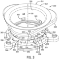
- FIG. 3 a perspective view shows portions 300 of a first example embodiment of an improved mounting assembly encompassed by the improved mounting assembly 208 of FIG. 2 , so as to highlight several features of that mounting assembly in particular.
- the portions 300 of the mounting assembly particularly include an upper mounting flange 310 that is one example of the improved upper mounting flange 210 shown in FIG. 2 , as well as a sink flange 314 that is one example of the improved sink flange 214 of FIG. 2 .
- the portions 300 also include a back-up flange 308 that can take a form that is similar to that of the back-up flange 108 of FIG. 1 .
- the portions 300 are shown independent of numerous other possible components or portions of the mounting assembly (e.g., the mounting assembly 208) and food waste disposer assembly (e.g., the food waste disposer assembly 200) of which those portions 300 would form a part. Further, the portions 300 are shown independent of any sink (e.g., the sink 202) or any other structure to which the mounting assembly encompassing the portions 300 would be attached, to facilitate an appreciation for the features and operation of the portions 300 in particular.
- a rim (or lip) 312 of the sink flange 314 when implemented in relation to the sink such as the sink 202, a rim (or lip) 312 of the sink flange 314 will be positioned so as to rest upon an upper surface of a floor of the sink. Also, when so implemented, a tubular section (or extension or portion) 316 of the sink flange 314 will extend through an orifice formed within the floor of the sink, from the upper surface of the floor to a location beneath the floor of the sink, at which the tubular section can be coupled to a food waste disposer such as the food waste disposer 206 of the FIG. 2 .
- the back-up flange 308 can be positioned immediately beneath the floor of the sink, between the upper mounting flange 310 and the sink 202 (and also between the upper mounting flange 310 and the rim 312 of the sink flange 314 as shown in FIG. 3 ).
- ramps (or inclined mounting fasteners or edges or ridges) 390 extending from sides of the upper mounting flange 310 particularly are structures by which a food waste disposer such as the food waste disposer 206 can be directly or indirectly coupled to the upper mounting flange and the mounting assembly 208, and thus attached to a sink (or possibly another structure) by way of that mounting assembly.
- the ramps 390 particularly allow for a lower locking ring or lower mounting flange such as the lower mounting flange 118 of FIG. 1 to be attached to the upper mounting flange 310 as described above in regard to FIG. 1 , with a mounting gasket such as the mounting gasket 116 positioned between those two flanges.
- the food waste disposer 206 (or other waste disposer) in turn is coupled to the lower mounting flange 118 as discussed above (e.g., by way of the mounting gasket 116), such an arrangement thus allows the waste disposer to be indirectly attached to the sink flange 314 by way of the upper mounting flange 310 and thereby indirectly attached by way of the mounting assembly 208 to a sink (or possibly another structure).
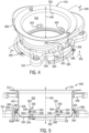
- FIG. 4 and FIG. 5 are also provided to show additional views of the portions 300. More particularly, it should be appreciated that the upper mounting flange 310 can be rotated about an axis 318 shown in each of FIG. 3 , FIG. 4, and FIG. 5 relative to the sink flange 314 (and the back-up flange 308), and while FIG. 3 shows the upper mounting flange 310 to have one rotational position relative to the sink flange 314, FIG. 4 and FIG. 5 show the portions 300 when the upper mounting flange 310 has a second rotational position relative to the sink flange 314.
- the sink flange 314 and the upper mounting flange 310 have complementary features that allow for the upper mounting flange to be secured to the sink flange by way of a three-step process described below.
- the tubular section 316 of the sink flange 314 includes multiple (in this example, six) protrusions 320 that are spaced equidistantly around the outer perimeter ofthe tubular section 316, proximate abottom edge 322 ofthe tubular section 316. Five ofthe protrusions 320 are particularly visible in FIG. 3 and four of the protrusions 320 are visible in FIG. 5 .
- the sink flange 314 and the tubular section 316 thereof including the protrusions 320 thereof in the present embodiment are formed from a sheet metal material such as stainless steel.
- a sheet metal material such as stainless steel.
- each of the protrusions 320 generally has a capsule-shaped form such that the respective protrusion has a respective width (or end-to-end arc length) dimension 328 that is larger than a respective height dimension 330, has respective top and bottom edges 332 and 334, respectively, and has respective left and right curved edges 336 and 338, respectively (as shown particularly in FIG. 5 ).
- the top and bottom edges 332 and 334 particularly are parallel to a first plane defined by the bottom edge 322 of the tubular section 316, as well as parallel to a second plane defined by the rim 312.
- the top and bottom edges 332 and 334 would extend in a horizontal direction relative to the ground, although in other installations and embodiments this need not be the case.
- the protrusions 320 are generally arranged so as to coincide with, or be positioned at or proximate to, a third plane that is in between the aforementioned first and second planes respectively defined by the bottom edge 322 and rim 312, respectively, with the third plane being substantially closer to the first plane of the bottom edge than to the second plane of the rim.
- the upper mounting flange 310 further has complementary features that allow for the upper mounting flange to engage and become secured to the sink flange by way of the protrusions 320.
- the upper mounting flange 310 includes multiple (in this example, six) indentations or relief cuts (or indentation formations) 340.
- the indentations 340 are spaced equidistantly around an inwardly-facing surface or inner circumference 342 of the upper mounting flange 310 that defines an orifice 350 into which the tubular section 316 of the sink flange 314 can be positioned (see also FIG. 4 ).
- each of the indentations 340 has a respective width (or arc length or length) 344 that is substantially the same as, or slightly larger than, the width dimension 328 of the protrusions 320. Further, each of the indentations 340 has a depth dimension 346, in terms of a radial extent outward from a radially-innermost edge portion 348 of the inner circumference 342, which is equal to or greater in extent than the distance each of the protrusions 320 extends outwardly from the outer cylindrical surface 324 of the tubular section 316. Given these features, it should be appreciated from FIG. 3 that, when the protrusions 320 are respectively aligned with respective ones of the indentations 340 as shown in FIG.
- rotation of the upper mounting flange 310 relative to the sink flange 314 as represented by an arrow 352 results in the axial securing of the upper mounting flange 310 relative to the sink flange 314, and along the axis 318.
- the securing occurs as a result of such rotation due to relative engagement of additional features referred to as lugs 360 formed on the upper mounting flange 310 relative to the protrusions 320.
- the upper mounting flange 310 includes multiple (in this example, six) of the lugs 360 that are spaced equidistantly apart from one another along an upper surface 358 of the upper mounting flange 310, where the upper surface 358 is the surface of the upper mounting flange that is generally orientated toward the rim 312 during installation rather than away from the rim.
- the lugs 360 are respectively positioned in between neighboring ones of the indentations 340 of the upper mounting flange 310, such that the indentations 340 and lugs 360 generally alternate with one another as one proceeds around the upper mounting flange and the inner circumference 342 thereof.
- each ofthe lugs 360 is separated from each ofthe neighboring ones ofthe indentations 340 by a respective inner ridge portion 356 ofthe upper mounting flange 310.
- each ofthe ridge portions 356 has an inner-most edge that corresponds to the inner circumference 342, each ofthe respective ridge portions 356 overhangs a region or channel 354 beneath that ridge portion (that is, farther away from the upper surface 358) that links the neighboring one ofthe indentations 340 adjacent to that ridge portion with the neighboring one of the lugs 360 also adjacent to that ridge portion (see for example one of the channels 354 that is visible in FIG. 3 ).
- the protrusions 320 can proceed from being aligned with the respective indentations 340 to being aligned with the respective lugs 360 by passing through the respective channels 354 when the upper mounting flange 310 is rotated relative to the sink flange 314.
- the cross-sectional view of the portions 300 taken along a line 5-5 of FIG. 4 reveals in further detail the shape of the lugs 360 and the manner in which the lugs interface with the protrusions 320 when the upper mounting flange 310 is rotated sufficiently relative to the sink flange 314 such that the protrusions engage the lugs. More particularly as shown, the respective lugs 360 extend upward from the upper surface 358 of the upper mounting flange 310 in an arched manner extending both axially away (along the axis 318) from that surface 358 and radially inwardly.
- Each of the respective lugs 360 includes a respective inner contact surface 362 that is curved so as to generally follow the external rounded contour of a respective one of the protrusions 320 when the upper mounting flange 310 is rotated so that the respective protrusion comes into contact with the respective lug. It should be appreciated from FIG. 5 that, when the protrusions 320 are positioned so as to be rotationally aligned with the respective lugs 360 and in contact with those lugs, the mounting flange 310 becomes assembled to and secured relative to the sink flange 314.
- the portions 300 can be assembled such that the upper mounting flange 310 is secured to the sink flange 314 by virtue of a three-step process.
- the process particularly includes: (1) positioning the upper mounting flange 310 so that the bottom edge 322 of the tubular section 316 is aligned with and positioned for entry into (or begins entering) the orifice 350, (2) moving the upper mounting flange 310 axially along the axis 318 toward the rim 312 of the sink flange 314 so that the protrusions 320 proceed into the indentations 340, and (3) then rotating the upper mounting flange 310 relative to the sink flange 314 about the axis 318 so that the protrusions 320 respectively pass from being within the respective indentations 340, through the respective channels 354, and into rotational alignment with the respective lugs 360, such that the lugs 360 are in contact with the respective protrusions and positioned between the respective protrusions and the rim 312.
- the upper mounting flange 310 can be disassembled/released from the sink flange 314 by performing the above-described steps in reverse. That is, to remove the upper mounting flange 310 from the sink flange 314 when starting from the state in which those components are assembled and secured relative to one another, one would (1) rotate (e.g., in a clockwise direction counter to the direction of the arrow 352) the upper mounting flange 310 about the axis 318 relative to the sink flange 314 so that the protrusions 320 respectively pass through the respective channels 354 so as to become aligned with the respective indentations 340 rather than the respective lugs 360, (2) moving the upper mounting flange 310 axially away from the rim 312 of the sink flange 314 so that the protrusions 320 pass through the indentations 340, and (3) taking or moving the upper mounting flange 310 away from the tubular section 316 of the sink flange 314
- the present disclosure is intended to encompass numerous other embodiments.
- the upper mounting flange 310 becomes secured relative to the sink flange 314 by rotating the upper mounting flange in a counter-clockwise direction corresponding to the direction ofthe arrow 352 relative to the sink flange 314, in other embodiments, securing can be accomplished by rotating the upper mounting flange relative to the sink flange in the opposite direction and, correspondingly, releasing ofthe upper mounting flange from the sink flange would involve rotation in the counter-clockwise direction.
- the protrusions 320 take a capsule-shaped form as described above, in other embodiments the shapes ofthe protrusions can be different.
- the protrusions can have an oval shape, a cylindrical shape, a circular shape, or a rectangular or substantially-rectangular shape.
- the contact surfaces 362 of the lugs 360 and/or the interfacing surfaces of the protrusions 320 can be ones in which the levels of the respective surfaces as viewed along the axis 318 can vary slightly as one proceeds rotationally along those surfaces.
- Such surface variation of the contact surfaces 362 and/or the interfacing surfaces can in some embodiments be complementary and, in other embodiments, only certain of those surfaces will have any variation.
- rotation of the upper mounting flange 310 relative to the sink flange 314 during installation can have a screw-type tightening effect (and, inversely, rotation in the opposite direction during removal can have a loosening effect).
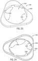
- the back-up flange 308 that can be employed among the portions 300 of the improved mounting assembly of FIG. 3 , FIG. 4, and FIG. 5 can take a form that is somewhat different from that of the back-up flange 108 of FIG. 1 .
- an outer perimeter 2300 of the back-up flange 308 can be identical or substantially the same as that of the back-up flange 108
- an inner orifice 2302 of the back-up flange 308 is defined by a combination of six radially inwardly-extending protrusions 2304 and six radially outwardly-extending indentations 2306, which alternate with one another as one proceeds circumferentially around the inner orifice 2302.
- each of the indentations 2306 is positioned in between a respective neighboring pair of the protrusions 2304, and vice-versa.
- each of the protrusions 2304 particularly not only extends radially-inwardly, away from the outer perimeter 2300 and toward a center of the inner orifice 2302 (e.g., toward the axis 318 of FIG. 3 ), but also includes a respective downwardly-extending lip 2308 (which is upwardly-extending as shown in FIG. 24 given the inverted orientation of the back-up flange 308 shown therein).
- the present example embodiment ofthe back-up flange 308 can differ from the back-up flange 108 particularly in that the back-up flange 308 includes the indentations 2306.
- the indentations 2306 are arranged as interruptions on the inner diameter of the back-up flange to accommodate the presence ofthe protrusions 320 on the tubular extension 316 ofthe sink flange 314 and to thereby permit assembly of the back-up flange in relation to the sink flange.
- the back-up flange 308 can be assembled to the sink flange 314 by positioning the back-up flange so that the bottom edge 322 of the tubular section 316 is aligned with and positioned for entry into (or begins entering) the inner orifice 2302, and moving the back-up flange 308 axially along the axis 318 (see FIG. 3 ) toward the rim 312 ofthe sink flange 314 past the protrusions 320.
- the indentations 2306 are spaced apart from one another along the back-up flange 308 in a manner that is complementary to the spacing ofthe protrusions 320 around the tubular extension 316 such that, so long as the back-up flange 308 is angularly positioned relative to the tubular extension so that the protrusions 320 are aligned with the indentations 2306, the back-up flange can be moved along the tubular extension 316 past the protrusions 320 toward the rim 312.
- portions 400 of a second example mounting assembly that can be encompassed by the mounting assembly 208 of FIG. 2 are shown by way of a perspective view, a cutaway perspective view, and a cross-sectional view, respectively.
- the perspective view provided by FIG. 7 shows the portions 400 rotated slightly about an axis 418 by comparison with the portions 400 as shown in FIG. 6 .
- FIG. 7 shows the portions 400 rotated slightly about an axis 418 by comparison with the portions 400 as shown in FIG. 6 .
- FIG. 8 not only shows a cross-sectional view of the additional portions 400 as shown in FIG. 6 , but also shows a cross-sectional view of a further portion that is a baffle 406 that is not shown in FIG. 6 (or FIG. 7 ), and that baffle also can be considered to be among the additional portions 400 even though not shown in FIG. 6 (or FIG. 7 ).
- the portions 400 include components that are identical or substantially or largely similar in many respects.
- the portions 400 include a sink flange 414 having each of a rim 412, a tubular section (or extension or portion) 416 extending about an axis 418, and multiple (in this case, again, six) protrusions 420 spaced equidistantly around an outer cylindrical surface 424 ofthe tubular section, which are located closer to abottom edge 422 of the tubular section than to the rim 412.
- each of the protrusions 420 shows each of the protrusions 420 as having a width dimension 428, aheight dimension 430, atop edge 432, abottom edge 434, aleft curved edge 436, and a right curved edge 438 (as viewed from outside ofthe tubular section 416) that respectively correspond to the width dimension 328, height dimension 330, top edge 332, bottom edge 334, left curved edge 336, and right curved edge 338 ofthe protrusions 320 of FIG. 5 .
- the portions 400 include an upper mounting flange 410 having indentations 440 and lugs 460, as well as channels 454 linking those indentations and lugs, and an orifice 450 within the upper mounting flange 410 that can receive the tubular section 416 ofthe sink flange 414.
- ramps (or inclined mounting fasteners or edges or ridges) 490 extending from sides of the upper mounting flange 410 particularly are structures by which a food waste disposer such as the food waste disposer 206 can be directly or indirectly coupled to the upper mounting flange (e.g., by way of a lower mounting flange as discussed above) and the overall mounting assembly, and thus attached to a sink (or possibly another structure).
- components/features 410, 412, 414, 416, 418, 420, 422, 424, 440, 450, 454, 460, and 490 of FIG. 6 , FIG. 7 , and FIG. 8 respectively correspond to, and are identical or substantially similar to, the components/features 310, 312, 314, 316, 318, 320, 322, 324, 340, 350, 354, 360, and 390 of FIG. 3 , FIG. 4, and FIG. 5 , respectively, except as described further below.
- the portions 400 are not shown as including a back-up flange corresponding to the back-up flange 308, such a back-up flange would often be present during installation by way of the portions 400.
- the upper mounting flange 410 is secured relative to the sink flange 414 in substantially the same manner as was described with respect to the embodiment of FIG. 3 , FIG. 4, and FIG. 5 .
- the protrusions 420, indentations 440, and lugs 460 permit the securing of the upper mounting flange 410 relative to the sink flange 414 by way of the same process as described above, namely, (1) positioning the upper mounting flange 410 so that the bottom edge 422 of the tubular section 416 is aligned with and enters the orifice 450, (2) moving the upper mounting flange 410 axially along the axis 418 toward the rim 412 of the sink flange 414 so that the protrusions 420 proceed into the indentations 440, and (3) then rotating the upper mounting flange 410 relative to the sink flange 414 about the axis 418 so that the protrusions 420 pass through the channels 454 and into alignment with the lugs 460 such that the lugs 460 are positioned between those protrusions and the rim 412.
- the portions 400 do have a significant additional feature relative to the portions 300 in that the sink flange 414 further includes multiple (in this example, again, six) additional protrusions 402 also formed along the tubular section 416. As shown, the additional protrusions 402 are orientated inversely relative to the protrusions 420 in that, while the protrusions 420 extend outward from the outer cylindrical surface 424, the additional protrusions 402 instead extend inwardly into the tubular section, into an internal passage 404 of the sink flange 414 toward the axis 418.
- the additional protrusions 402 are positioned at the same axial location along the axis 418 as are the protrusions 420, and each ofthe additional protrusions 402 is respectively positioned midway in between a respective pair of neighboring ones ofthe protrusions 420 (and vice versa) arranged along the tubular section 416. It should be recognized that the back-up flange 308 described above would still be suitable for use with the sink flange 414, notwithstanding the presence ofboth the protrusions 420 and the additional protrusions 402, given that the additional protrusions 402 are inwardly-extending.
- FIG. 8 a cross-sectional view of the portions 400, taken along a line 8-8 of FIG. 6 , is additionally provided.
- the particular cross-sectional view provided in FIG. 8 is analogous to that shown in FIG. 5 , and particularly illustrates how two of the protrusions 420 are positioned within or under, so as to be in contact with, two of the lugs 460 when the upper mounting flange 410 is secured relative to the sink flange 414.
- FIG. 8 also illustrates more particular features of the additional protrusions 402.
- the additional protrusions 402 are capsule-shaped, although in other embodiments the additional protrusions can have other shapes (e.g., oval/elliptical, cylindrical circular, rectangular, or substantially rectangular shapes).
- each of the additional protrusions includes a respective width dimension 468 and a respective height dimension 470, where the width dimension is substantially greater than the height dimension.
- each of the protrusions 402 includes top and bottom edges 472 and 474, respectively, which are both linear, as well as left and right curved edges 476 and 478, respectively.
- top and bottom edges 472 and 474 are not exactly horizontal or parallel to a plane formed by the bottom edge 422 of the tubular section 416, but rather are slightly sloped, for reasons described further below. Nevertheless, in other embodiments, the top and bottom edges 472 and 474 can be parallel to the plane formed by the bottom edge 422 or arranged in another manner.
- FIG. 8 shows an additional portion, namely the baffle 406, to be positioned within the internal passage 404 of the sink flange 414, and this baffle can be considered to be among the portions 400.
- the baffle 406 can be a removable baffle formed from rubber (e.g., nitrile rubber) or other flexible material(s) (e.g., polypropylene, nylon, or a thermoplastic elastomer (TPE)) such that, when implemented as part of a food waste disposer assembly such as the food waste disposer assembly 200, the baffle can restrict or otherwise influence or affect the passage of food or other waste from the sink into and out of the food waste disposer.
- rubber e.g., nitrile rubber
- other flexible material(s) e.g., polypropylene, nylon, or a thermoplastic elastomer (TPE)
- the baffle 406 is not shown to be fully in position relative to where it would be positioned upon being fully implemented relative to the sink flange 414, but rather is shown to be positioned within the internal passage 404 slightly above the position it would take when fully implemented. That is, the baffle 406 is shown to be axially moved away from the bottom edge 422 of the tubular section 416 toward the rim 412 of the sink flange 414 along the axis 418 relative to where it would be when fully implemented in the sink flange 414.
- the additional protrusions 402 are particularly configured to serve as a support for the baffle 406 when the baffle is fully implemented.
- the baffle 406 includes multiple (in this example, six) support features 408 positioned around an outer rim of the baffle 406.
- the support features 408 are configured particularly to rest upon the additional protrusions 402 when the baffle is moved axially toward the bottom edge 422 away from the rim 412 of the sink flange 414 such that the support features contact the additional protrusions 402.
- the support features 408 particularly are configured to have sloped underside edges 409.
- the support features 408 are complementary in shape to the additional protrusions 402 given that the top edges 472 of the additional protrusions are sloped as described above. Consequently, when the support features 408 are resting on the top edges 472 of the additional protrusions 402, the baffle 406 (and particularly an outer rim of the baffle) takes on a position that is parallel or substantially parallel to the bottom edge 422 of the tubular section 416.
- a baffle suited for engaging the additional protrusions 402 can take other forms as well.
- an outer rim or perimeter of such a baffle can have multiple dimples (or indentations or negative features) arranged around that outer rim or perimeter that respectively correspond to, in terms of their respective positions relative to, and that are respectively complementary in shape relative to, the respective additional protrusions 402.
- a baffle with an outer rim having six complementary inverted-capsule-shaped dimples would be appropriate.
- Such a baffle would be implemented in relation to the sink flange 414 by pushing the baffle into place within the sink flange such that the additional protrusions 402 snapped into the corresponding dimples on the baffle perimeter. Since such a baffle would be elastomeric, it would deform to allow this mating of the dimples on the baffle perimeter with the additional protrusions 402. Further, when so positioned, the dimples would surround the additional protrusions 402 and increase the resistance to baffle movement up or down along the axis 418 (e.g., vertically).
- Such a manner of implementation would be advantageous insofar as it would resemble in feel, as perceived by an installer, the feel of a conventional arrangement in which a baffle can be implemented or locked in relation to a strainer flange by way of a complementary snap ring groove arrangement (e.g., in which a groove circumferentially extending around one of the baffle or the inner perimeter of the strainer flange is configured to mate with a complementary annular formation circumferentially extending about the other of those components).
- a complementary snap ring groove arrangement e.g., in which a groove circumferentially extending around one of the baffle or the inner perimeter of the strainer flange is configured to mate with a complementary annular formation circumferentially extending about the other of those components.
- the sink flange 414 is particularly configured to support and engage baffles such as the baffle 406 that are complementary to one or more of the features of the additional protrusions 402. More particularly, in embodiments in which the additional protrusions 402 are capsule-shaped and have top edges 472 that are sloped as described above, the sink flange 414 is configured to support and engage baffles with support features that have one or more complementary characteristics such as, for example, the particular sloped shape ofthe support features 408, or the complementary inverted-capsule-shape ofthe dimples also discussed above.
- baffles with support features having a different configuration than those suitable for the sink flange 414 e.g., different from the support features 408 or the complementary inverted-capsule-shaped dimples described above
- the additional protrusions 402 will be appropriate for use with the sink flange having those additional protrusions.
- the top edges 472 ofthe additional protrusions 402 are parallel to the bottom edge 422 ofthe sink flange 414, then that arrangement will be appropriate for a baffle having complementary support features (for example, having bottom edges that were horizontal or parallel to the rim of the baffle). In this manner, only certain versions of baffles will be suited for the sink flange 414, and other versions of baffles will not fit properly with respect to the sink flange.
- FIG. 9 and FIG. 10 are provided, which respectively show a bottom plan view of the sink flange 414 and a side elevation view of the sink flange taken along a line 10-10 of FIG. 9.
- FIG. 9 particularly shows that, in the present embodiment, each of the protrusions 420 extends outward from the outer cylindrical surface 424 by a distance of 0.1 inches (0.254 cm). It can be seen that each of the protrusions 420 extends outward by first and second radiused edges 900 and 902, which are then linked by a curved (approximately straight) circumferential perimeter segment or edge 904.
- the radiused edges each have an outer radius of 0.06 inches (0.1524 cm) and the overall width of each of the protrusions 420 corresponding to the width dimension 428 of each of those protrusions as shown in FIG. 6 in the present example is 0.414 inches (1.0516 cm).
- the radiused edges 900 and 902 generally correspond in extent with the curved edges 436 and 438, and the edge 904 generally corresponds in extent with the top and bottom edges 432 and 434.
- each of the protrusions 402 has an outer radius of 0.08 inches (0.2032 cm), and each of the top and bottom edges 472 and 474 has a length of approximately 0.565 inches (1.4351 cm).
- an inner flat portion 1002 of the protrusions 420 in this embodiment has a dimension of 0.138 inches (0.35 cm).
- each of the additional protrusions 402 is, in this embodiment, 0.073 inches (0.185 cm). Further, although the aforementioned dimensions described in relation to FIG. 9 and FIG. 10 are provided as examples, it should be understood that the present disclosure is not at all limited to embodiments having any of these dimensions, but rather the present disclosure is intended to encompass numerous other embodiments having features with any of a variety of other dimensions.
- FIG. 11 provides a perspective cutaway view of one of the lugs 460 interfacing one of the protrusions 420
- FIG. 12 shows a cross-sectional view taken along a line 12-12 of FIG. 11 illustrating in even further detail the lug 460 and protrusion 420 of FIG. 11 interfacing one another.
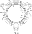
- FIG. 13 a further, bottom plan view of the portions 400 is further provided.
- the protrusions 420 are shown to be engaged with the lugs 460 from a vantage point of looking from the upper mounting flange 410 and bottom edge 422 of the tubular section 416 of the sink flange 414 toward the rim 412 of the sink flange. Also visible in FIG. 13 are the indentations 440.
- FIG. 12 it should be particularly evident from FIG. 12 how a contact surface 462 of the lug 460 shown therein interfaces the protrusion 420 shown therein (where the contact surface 462 also corresponds to one of the contact surfaces 362 of FIG. 5 ). Also evident from FIG. 12 is a shape of the lug 460, which is shown to have an undulating profile as it extends upward toward the rim 412 (not shown) of the sink flange 414, in a direction parallel to the axis 418, and also radially inwardly towards the sink flange.
- the lug 460 is shown to include a first section 1202 that extends generally upwardly, a second section 1204 that extends generally radially inwardly, a third section 1206 that again extends generally upwardly, and a final section 1208 that again extends radially inwardly.
- an upper curved region 1210 of the contact surface 462 of the lug 460 extending along the sections 1206 and 1208 particularly engages a counterpart contact surface 1212 of the protrusion 420.
- the upper mounting flange 410 particularly is precluded from moving downwardly relative to the tubular section 416 of the sink flange 414, that is, precluded from moving away from the rim 412 toward the bottom edge 422 of the sink flange.
- a tangent overlap distance (or contact surface length) over which the contact surface 462 and counterpart contact surface 1212 are in contact is 0.074 inches (0.188 cm) assuming that the radius on the protrusions 420 (or bumps) is 0.100 inches (0.254 cm).
- the width of each of the lugs 460 (or extensions or tabs) is 0.454 inches (1.153 cm).
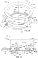
- portions 1400 of a third example mounting assembly that can be encompassed by the mounting assembly 208 of FIG. 2 are shown by way of a perspective view and in a cross-sectional view, respectively. Similar to the portions 400 shown in FIG. 6 , FIG. 7 , and FIG. 8 , the portions 1400 do not include a back-up flange corresponding to the back-up flange 308, although it should be appreciated that such a back-up flange would typically be present during installation of a food waste disposer assembly by way of the portions 1400. Also, it should be appreciated from inspection of FIG. 14 and FIG. 15 relative to FIG. 6 and FIG.
- the portions 1400 include components/features that are identical or substantially or largely similar to those of the portion 400 in many respects.
- the portions 1400 include components/features 1402, 1410, 1412, 1414, 1416, 1418, 1420, 1422, 1424, 1440, 1450, 1454, and 1460 shown in FIG. 14 and FIG. 15 that respectively correspond to, and are identical or substantially similar to, the components/features 402, 410, 412, 414, 416, 418, 420, 422, 424, 440, 450, 454, and 460 shown in FIG. 6 and FIG. 8 , respectively, except as described further below.
- the portions 1400 include a sink flange 1414 having each of a rim 1412, a tubular section (or extension or portion) 1416 coaxial about an axis 1418, and multiple protrusions 1420 spaced equidistantly around an outer cylindrical surface 1424 of the tubular section and located closer to a bottom edge 1422 of the tubular section than to the rim 1412.
- Each of the protrusions 1420 has a width dimension 1428, a height dimension 1430, a top edge 1432, a bottom edge 1434, a left curved edge 1436, and a right curved edge 1438 as viewed from the outside of the tubular section 1416 (note that FIG.
- the portions 1400 include an upper mounting flange 1410 having indentations 1440 and lugs 1460, as well as an orifice 1450 within the upper mounting flange 1410 that can receive the tubular section 1416 of the sink flange 1414.
- the portions 1400 also include channels corresponding to the channels 454 of the portions 400, which are formed in the upper mounting flange 1410 and link neighboring ones of the lugs 1460 and indentations 1440.
- ramps (or inclined mounting fasteners or edges or ridges) 1490 extending from sides of the upper mounting flange 1410 particularly are structures by which a food waste disposer such as the food waste disposer 206 can be directly or indirectly coupled to the upper mounting flange and the overall mounting assembly (e.g., by way of a lower mounting flange as discussed above), and thus attached to a sink (or possibly another structure).
- the portions 1400 include multiple additional protrusions 1402 spaced equidistantly around the outer cylindrical surface 1424 of the sink flange 1414, at the same axial position along an axis 1418 as the protrusions 1420.
- Each of the additional protrusions 1402 is spaced equidistantly in between a respective pair of neighboring ones of the protrusions 1420 (and vice-versa).
- each of the additional protrusions 1402 (as with the protrusions 420) is capsule-shaped. Given this capsule-shape, each of the additional protrusions 1402 includes a respective width dimension 1468 and a respective height dimension 1470, where the width dimension is substantially greater than the height dimension.
- each of the additional protrusions 1402 further includes top and bottom edges 1472 and 1474, respectively, which are both linear, as well as left and right curved edges 1476 and 1478, respectively.
- the top and bottom edges 1472 and 1474 of the additional protrusions 1402 are not exactly horizontal or parallel to a plane formed by the bottom edge 1422 of the tubular section 1416, but rather are slightly sloped, for reasons described further below. Notwithstanding the above description, however, in other embodiments the protrusions 1420 and additional protrusions 1402 can have other shapes (e.g., oval or elliptical, cylindrical, circular, or rectangular or substantially rectangular), and the additional protrusions can have top and bottom edges that are parallel to the plane of the bottom edge 1422.
- the additional protrusions (or baffle retaining features) 1402 for baffle retention purposes than the number of protrusions (or bumps) 1420 that are present for interlocking with upper mounting flange features such as the lugs 1460.
- the additional protrusions 1420 in one alternate embodiment only three of the additional protrusions for baffle retention purposes can be present.
- a smaller number of additional protrusions used for baffle retention can simplify the manufacture of the sink flange by reducing the number of features needing to be stamped into the sink flange.
- protrusions 1420, indentations 1440, lugs 1460, and additional protrusions 1402 respectively are intended to serve substantially the same functional purposes as the protrusions 420, indentations 440, lugs 460, and additional protrusions 402, respectively.
- the protrusions 1420, indentations 1440, and lugs 1460 permit the securing of the upper mounting flange 1410 relative to the sink flange 1414 by way of the same process as described above, namely, (1) positioning the upper mounting flange 1410 so that the bottom edge 1422 of the tubular section 1416 is aligned with and enters the orifice 1450, (2) moving the upper mounting flange 1410 axially along the axis 1418 toward the rim 1412 of the sink flange 1414 so that the protrusions 1420 proceed into the indentations 1440, and (3) then rotating the upper mounting flange 1410 relative to the sink flange 1414 about the axis 1418 so that the protrusions 1420 pass through the channels and into alignment with the lugs 1460 such that the lugs 1460 are positioned between those protrusions and the rim 1412.
- portions 1400 can also include a baffle corresponding to the baffle 406 of FIG. 8 , and that such a baffle can be supported within the sink flange 1412 by way of the additional protrusions 1402.
- the portions 1400 differ from the portions 400 in that, rather than having six of the protrusions 420, six of the indentations 440, and six of the lugs 460, the portions 1400 instead have three of the protrusions 1420, three of the indentations 1440, and three of the lugs 1460. Further, it should be recognized by a comparison of FIG. 14 with FIG. 4 that the protrusions 1420 are substantially larger than the protrusions 420, particularly insofar as the width dimension 1428 of each of the protrusions 1420 is larger than the width dimension 428 of each of the protrusions 420.
- the protrusions 1420 are different in number and in their dimensions relative to the protrusions 420, it should be recognized that, if a back-up flange corresponding to the back-up flange 308 described above is employed in relation to the portions 1400, such a back-up flange can have as few as three radially outwardly-extending indentations corresponding to the indentations 2306, but such indentations would have larger angular extents than the indentations 2306 so as to accommodate the protrusions 1420. Also, instead of the portions 1400 having six of the additional protrusions 402, there are three of the additional protrusions 1402 that are present.
- the additional protrusions 1402 serve to support a baffle in substantially the same manner as the baffle 406 is supported upon the additional protrusions 402 as shown in FIG. 8
- a baffle in the case of the embodiment of FIG. 14 and FIG. 15 would have sloped support features that would be appropriately configured to rest upon the three of the additional protrusions 1402 rather than the six of the additional protrusions 402.
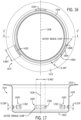
- FIG. 16 and FIG. 17 are provided, which respectively show a bottom plan view of the sink flange 1414 and a cross-sectional view of the sink flange taken along a line 17-17 of FIG. 16.
- FIG. 16 particularly shows that, in the present example embodiment, each of the protrusions 1420 extends outward from the outer cylindrical surface 1424 by a distance of 0.1 inches (0.254 cm). It can be seen that each of the protrusions 1420 extends outward by first and second radiused edges 1600 and 1602, which are then linked by a curved (approximately straight) circumferential perimeter segment or edge 1604.
- each of the radiused edges 1600, 1602 has an outer radius of 0.06 inches (0.1524 cm) and the overall width of each of the protrusions 1420 corresponding to the width dimension 1428 of each of those protrusions as shown in FIG. 16 in the present example is 0.891 inches (2.2631. cm).
- the radiused edges 1600 and 1602 generally correspond to the curved edges 1436 and 1438, and the edge 1604 generally corresponds in extent with the top and bottom edges 1432 and 1434.
- each of the additional protrusions 1402 has an outer radius of 0.08 inches (0.2032 cm), and also each of the top and bottom edges 1472 and 1474 has a length of approximately 0.661 inches (1.6789 cm).
- an inner flat portion 1702 of each of the protrusions 1420 in this embodiment has a dimension of 0.138 Inches (0.3505 cm).
- the depth of the additional protrusions 1402 again is, in this embodiment, 0.073 inches (0.1854 cm).
- the embodiment of the mounting assembly employing the portions 1400 of FIG. 14, 15 , 16, and 17 differs from the embodiment employing the portions 400 of FIG. 6 through FIG. 13 in several respects.
- the embodiment with the portions 1400 has three protrusions (or bumps) 1420 allowing for assembly of the upper mounting flange 1410 to the sink flange 1414, as well as three additional protrusions (or baffle retaining features) 1402 allowing for a baffle (not shown) to be mounted within the sink flange.
- the embodiment employing the portions 1400 permits a simplified stamping process to be utilized for manufacturing the sink flange 1414 and the upper mounting flange 1410.
- the protrusions 1420 are twice as wide as the protrusions 420 (e.g., in terms of the width dimension 1428 versus the width dimension 428), the protrusions 1420 are capable of bearing the loading upon the sink flange 1414 from the upper mounting flange 1410 notwithstanding there only being three of the protrusions 1420 instead of six of the protrusions 420.
- the embodiment having the protrusions 420 has six of those protrusions (each of which is half as wide as the protrusions 1420), the load from the mounting flange is distributed at more locations than the embodiment employing three of the protrusions 1420.
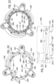
- portions 1800 of a fourth example mounting assembly that can be encompassed by the mounting assembly 208 of FIG. 2 are shown by way of a front perspective view.
- the portions 1800 include several components that are identical or substantially (or largely) similar in many respects to those of one or more of the other embodiments of mounting assemblies described above and, more particularly, to the portions 400 of the second example mounting assembly described above in regard to FIG. 6 .
- the portions 1800 include the sink flange 414 having the rim 412, the tubular section (or extension or portion) 416 extending about the axis 418 between the rim 412 and bottom edge 422 (see FIG.
- the six protrusions 420 are spaced equidistantly around the outer cylindrical surface 424 of the tubular section, and each of the additional protrusions 402 is respectively positioned midway in between a respective pair of neighboring ones of the protrusions 420 (and vice-versa) arranged along the tubular section 416.
- the portions 1800 of FIG. 18 also include a back-up flange 1808 corresponding to the back-up flange 308 (which, as discussed above, is often present during installation with respect to the portions 400 of FIG. 6 even though not shown in FIG. 6 ).
- the portions 1800 include an upper mounting flange 1810, which corresponds, in terms of its position and role, to the upper mounting flange 410 shown in FIG. 6 .
- the upper mounting flange 1810 is shown to be coupled to the back-up flange 1808 by back-up screws 1806 (two of which are shown, and which correspond in their role to the bolts 112 described above with respect to FIG. 1 ).
- the upper mounting flange 1810 includes an orifice 1850 that can receive the tubular section 416 of the sink flange 414.
- the upper mounting flange 1810 includes ramps (or inclined mounting fasteners or edges or ridges) 1890 extending from sides of the upper mounting flange 1810.
- the ramps 1890 are structures by which a food waste disposer such as the food waste disposer 206 can be directly or indirectly coupled to the upper mounting flange (e.g., by way of a lower mounting flange as discussed above) and the overall mounting assembly, and thus attached to a sink (or possibly another structure).
- the upper mounting flange 1810 has several features that differ from those of the upper mounting flange 410.
- the upper mounting flange 1810 includes six lugs 1860 and six indentations 1840 that respectively differ, in terms of their structures, relative to the lugs 460 and indentations 440, respectively, of the upper mounting flange 410.
- each of the lugs 1860 takes the form of a flat ledge or flat land having a respective upper surface 1884 and a respective lower surface 1896.
- Each of the lugs 1860 extends radially inwardly from a main circumferential body 1812 of the upper mounting flange 1810 into the orifice 1850 (e.g., toward the position of the central axis 418 when the sink flange 414 and upper mounting flange 1810 are assembled with one another as shown in FIG. 18 ). Although each of the lugs 1860 extends radially inwardly, the lugs 1860 do not extend upward above an upper surface 1858 of the upper mounting flange 1810, as was the case with the lugs 460 of the upper mounting flange 410.
- each of the lugs 1860 has respective first and second ends 1876 and 1878, and extends circumferentially around the orifice 1850 between those respective first and second ends.
- the indentations 1840 are respectively positioned between respective pairs of neighboring ones of the lugs 1860 (e.g., between the first end 1876 of a first respective neighboring one of the lugs and the second end 1878 of a second respective neighboring one of the lugs) and spaced around the orifice 1850.
- the indentations 1840 can be considered as forming radially-outermost portions of the orifice 1850 that extend between the respective pairs of the lugs 1860, radially outwardly to the main circumferential body 1812.
- each of the lugs 1860 includes a respective pair of first and second dimple features 1872 and 1874 that are respectively positioned at or proximate to the first and second ends 1876 and 1878, respectively, of the respective lug.
- One example pair of the first and second dimple features 1872 and 1874 of one of the lugs 1860 is particularly illustrated in a detail view 1880 of a portion of the upper mounting flange 1810 shown in FIG. 21 (with that detail view corresponding to a region 1882 shown in FIG. 20 ), again with the upper mounting flange 1810 being oriented in accordance with the bottom perspective view shown in FIG. 20 . It should be appreciated from FIG. 19 , FIG. 20, and FIG.
- first and second depressions 1886 and 1888 respectively are present at or proximate to the respective first and second ends 1876 and 1878 of each respective lug, at the locations of the first and second dimple features 1872 and 1874, respectively, of each respective lug.
- first and second raised features 1892 and 1894 respectively are present at or proximate to the respective first and second ends 1876 and 1878 of each respective lug, at the locations of the first and second dimple features 1872 and 1874, respectively, of each respective lug.
- compressions and “raised features” are used with respect to the features 1886, 1888 1892, and 1894, it should be appreciated that the use of these terms is not intended to imply directional orientations of these structures relative to the ground, but rather are intended to imply directional orientations of these structures relative to other features of the lugs 1860, such as the lower surfaces 1896 or upper surfaces 1884.
- FIG. 22 a bottom perspective view is provided showing a combination of the upper mounting flange 1810 and sink flange 414 when those two components are assembled with one another.
- the upper mounting flange 1810 can be secured relative to the sink flange 414 in a manner that is highly similar to that described with respect to the embodiment of FIG. 6 , FIG. 7 , and FIG. 8 (as well as other embodiments described above, such as that of FIG. 3 , FIG. 4, and FIG. 5 ).
- the protrusions 420, indentations 1840, and lugs 1860 permit the securing of the upper mounting flange 1810 relative to the sink flange 414 by way of the same process as described above, namely, (1) positioning the upper mounting flange 1810 so that the bottom edge 422 of the tubular section 416 is aligned with and enters the orifice 1850, (2) moving the upper mounting flange 1810 axially along the axis 418 toward the rim 412 of the sink flange 414 so that the protrusions 420 proceed into (and through) the indentations 1840, and (3) then rotating the upper mounting flange 1810 relative to the sink flange 414 about the axis 418 so that the protrusions 420 pass under and into alignment with the lugs 1860, such that the lugs 1860 (including portions of radially-inwardmost edges or tips 1898 thereof, as shown in FIG. 20 ) are positioned between those protrusions and the rim 412.
- the upper mounting flange 1810 of FIGs. 18-22 lacks any structures corresponding to the ridge portions 356 that are positioned to the sides of the lugs 360 and that overhang a region or define any channel as discussed in regard to FIGs. 3 and 4 above. Rather, it is only the lugs 1860 that extend radially inwardly from the main circumferential body 1812 of the upper mounting flange 1810.
- rotation of the upper mounting flange 1810 relative to the sink flange 414 about the axis 418 during assembly merely involves moving the respective protrusions 420 from respective positions within the respective indentations 1840 to respective positions that are in alignment with and under the respective lugs 1860, between the respective first and second raised features 1892 and 1894 associated with the respective first and second dimple features 1872 and 1874 of the respective lugs 1860.
- first and second dimple features 1872 and 1874 of the lugs 1860 play a significant role in maintaining the upper mounting flange 1810 in an assembled state relative to the sink flange 414. That is, by providing the lugs 1860 with the first and second dimple features 1872 and 1874, and particularly the first and second raised features 1892 and 1894 respectively associated with those respective dimple features, the respective protrusions 420 tend to be retained in their respective positions between the respective first and second dimple features 1872 and 1874 of the respective lugs 1860 after the upper mounting flange 1810 has been rotated relative to the sink flange 414 sufficiently so that the respective protrusions 420 attain such positions.
- the upper mounting flange 1810 with the flat ledges or lands with the raised features 1892, 1894 (or raised edges) as the lugs 1860, it becomes less likely for the sink flange (or strainer flange) 414 to rotate to a point where the protrusions (or "bumps") 420 on the sink flange move past the ends 1876 and 1878 of the lugs (or "fall off' the edges of the flat ledges, to the extent the lower surfaces 1896 of the lugs 1860 are viewed as support surfaces for the protrusions, e.g., as illustrated in FIG. 2 ).
- the respective first and second raised features 1892 and 1894 associated with the respective lugs 1860 tend to serve as stops for the protrusions 420, and tend to prevent inadvertent excessive rotation of the upper mounting flange 1810 relative to the sink flange 414 after the upper mounting flange and sink flange have been assembled together.
- this arrangement tends to prevent accidental disengagement of the upper mounting flange 1810 from the sink flange 414.
- the distances between the first and second dimple features 1872 and 1874 of any given one ofthe lugs 1860 are considerably greater than the width dimension 428 ofthe protrusion 420 (as discussed in relation to FIG. 6 ). Consequently, although the first and second dimple features 1872 and 1874 ofthe lugs 1860 tend to retain the protrusions 420 when the protrusions are positioned between the first and second raised features 1892 and 1894 associated with those respective dimple features, the lugs do not tend to strictly limit or lock in place those protrusions 420 in particular positions beneath the lugs.
- the lugs 460 of FIG. 6 can be considered locking lugs that create defined spaces where protrusions on the sink flange are intended to end up when the upper mounting flange is assembled to the sink flange).
- a mounting assembly can include the portions 1800 except insofar as the additional protrusions 402 are not present (e.g., similar to as shown in FIG. 3 ).
- the number of lugs 1860 can be reduced or increased, from six, for example, if the number of protrusions 420 also correspondingly is reduced or increased.
- the portions 1800 are configured such that the first and second dimple features 1872 and 1874 are respectively positioned at or in close proximity to the first and second ends 1876 and 1878 respectively
- the lugs 1860 can include end extensions that extend angularly outward farther from the dimple features, such that the dimple features are more inwardly-positioned along the lugs, away from the ends of the lugs.
- such end extensions can be considered to correspond to the ridge portions 356 discussed above.
- the lugs 1860 can be flat along their lengths and lack any of the first and second dimple features 1872 and 1874, the first and second depressions 1886 and 1888, and the first and second raised features 1892 and 1894, or the lugs can respectively have only one of the dimple features and associated depression and raised feature at one of the ends of the respective lug (but not the other end).
- Embodiments of mounting assemblies encompassed herein can provide any one or more of a variety of advantages.
- one or more of the embodiments encompassed herein achieve a mounting assembly by which an upper mounting flange can be easily and straightforwardly attached to a sink flange, and therefore facilitates the attachment of a waste disposer such as a food waste disposer to a structure such as a sink.
- Such embodiments particularly eliminate or minimize the difficulties associated with snap ring removal and reinstallation. Securing of the upper mounting flange to the sink flange in at least some embodiments can be achieved without the use of a snap ring or retaining ring.
- the process of installation can simply involve positioning the upper mounting flange in relation to the sink flange, sliding the upper mounting flange relative to the sink flange past the protrusions (e.g., the protrusions 320, 420, or 1420) so the protrusions are within (or pass through) complementary indentations, and turning the upper mounting flange relative to the sink flange so that the protrusions are secured relative to the lugs (e.g., the lugs 360, 460, 1460, or 1860).
- the protrusions e.g., the protrusions 320, 420, or 1420
- the operation of the protrusions (e.g., the protrusions 320, 420, or 1420) of the sink flange relative to the features of the upper mounting flange effectively involves providing of a groove or support on which the upper mounting flange can sit or rest, and provides the installer with feedback that successful securing of the upper mounting flange with the sink flange has been achieved.
- one or more of the mounting assemblies encompassed herein are configured to provide desirable load distribution.
- one or more of the embodiments encompassed herein provide a new manner ofretaining a baffle (especially a removable baffle), by way of the use of additional protrusions such as the additional protrusions 402 or 1402 that are different from conventional snap ring retaining features. Further, as already discussed above, such additional protrusions in at least some embodiments are angled or sloped, rather than being within a horizontal plane or plane perpendicular to the axis along which the tubular section of the sink flange extends (such as any of the axes 318, 418, and 1418).
- baffles that are intended for use with the sink flange 1412 having the additional protrusions 1402 would tend not to be usable in other sink flanges for which those baffles are not intended to be used.
- one or more of such embodiments encompassed herein allow for a mounting assembly (and overall food waste disposer assembly) to be implemented that is compatible with standard sink hole dimensions and does not change the depth of the sink with which the mounting assembly (and overall food waste disposer assembly) can be implemented.
- the sink (or strainer) flange including the protrusions formed thereon e.g., the protrusions 320, 420, or 1420
- the protrusions 320, 420, or 1420 can be sized to fit within industry standard sink drain openings. Any complementary notches/depressions formed within the interior of the sink flange arising from the presence of those protrusions will be covered by a baffle implemented within the sink flange.
- one or more of such embodiments encompassed herein remain backwards compatible with existing waste disposer designs and mounting gaskets. Further, one or more of such embodiments encompassed herein can be implemented using a thin sink flange (or strainer flange), which maximizes opening diameter and reduces how much the sink flange might protrude up into a sink. Thus, at least some of the embodiments described herein facilitate the ease of installing a waste disposer by eliminating or reducing the difficulty level associated with installation, particularly in terms of the attachment of an upper mounting flange to a sink flange, and at the same time remain backwards compatible and dimensionally identical or substantially similar to older mounting features/components.
- the use of the lugs 1860 with the flat ledges or lands makes it possible to assemble the upper mounting flange 1810 with respect to the sink flange 414 without locating pockets for the protrusions 420, since the flat ledges or lands (or ramps) can offer more surface area to provide support (e.g., along the lower surfaces 1896 of the respective lugs 1860, between the respective first and second raised features 1892 and 1894 of the respective lugs).
- the upper mounting flange 1810 having (and because of its having) the lugs 1860 with flat ledges can be manufactured by way of a simpler process, such as by way of a stamping process, by comparison with some other embodiments.
Landscapes
- Engineering & Computer Science (AREA)
- General Engineering & Computer Science (AREA)
- Mechanical Engineering (AREA)
- Environmental & Geological Engineering (AREA)
- Health & Medical Sciences (AREA)
- Life Sciences & Earth Sciences (AREA)
- Hydrology & Water Resources (AREA)
- Public Health (AREA)
- Water Supply & Treatment (AREA)
- Crushing And Pulverization Processes (AREA)
- Sink And Installation For Waste Water (AREA)
Claims (15)
- Ein Befestigungssystem (400; 1400; 1800) zum Befestigen einer Abfallentsorgungsvorrichtung (200), wobei das Befestigungssystem Folgendes beinhaltet:eine erste Flanschkomponente (414; 1414) mit einem ersten (412; 1412) und einem zweiten (422; 1422) Ende und einer röhrenförmigen Struktur (416; 1416) mit einer zylindrischen Außenfläche (424; 1424), wobei sich die röhrenförmige Struktur (416; 1416) entlang einer ersten Achse (418; 1418) zwischen dem ersten (412; 1412) und dem zweiten (422; 1422) Ende erstreckt;eine Befestigungsflanschkomponente (410; 1410; 1810) mit einer inneren Kante, die mindestens teilweise eine Öffnung (450; 1450) definiert, die sich durch die Befestigungsflanschkomponente (410; 1410; 1810) erstreckt und derart bemessen ist,dass ein das zweite Ende (422; 1422) umfassender erster Abschnitt (422; 1422) der röhrenförmigen Struktur (416; 1416) teilweise in oder ganz durch die Öffnung (450; 1450) gelangen kann,wobei, wenn der erste Abschnitt (422; 1422) der röhrenförmigen Struktur (416; 1416) in der Öffnung (450; 1450) aufgenommen ist, sich sowohl die Öffnung (450; 1450) als auch die röhrenförmige Struktur (416; 1416) entlang der ersten Achse (418; 1418) erstrecken,wobei die röhrenförmige Struktur (416; 1416) eine Vielzahl von ersten Vorsprüngen (420; 1420) umfasst, die sich von der zylindrischen Außenfläche (424; 1424) radial nach außen erstrecken, wobei die Vielzahl von ersten Vorsprüngen (420; 1420) einen ersten der ersten Vorsprünge (420; 1420) und einen oder mehrere zusätzliche der ersten Vorsprünge (420; 1420) umfasst,wobei die Befestigungsflanschkomponente (410; 1410; 1810) eine Vielzahl von Nasen (460; 1460; 1860) mit jeweiligen Spitzen nah bei oder entlang der inneren Kante umfasst, wobei die Vielzahl von Nasen (460; 1460; 1860) eine erste der Nasen (460; 1460; 1860) und eine oder mehrere zusätzliche der Nasen (460; 1460; 1860) umfasst, wobei die jeweiligen Nasen (460; 1460; 1860) um die Öffnung (450; 1450) herum angeordnet sind und die jeweiligen ersten Vorsprünge (420; 1420) um die zylindrische Außenfläche (424; 1424) herum angeordnet sind, sodass, wenn der erste Abschnitt (422; 1422) der röhrenförmigen Struktur (416; 1416) derart in der Öffnung (450; 1450) positioniert ist, dass die erste der Nasen (460; 1460; 1860) in Drehrichtung auf den ersten der ersten Vorsprünge (420; 1420) um die erste Achse (418; 1418) ausgerichtet ist, jede der einen oder der mehreren zusätzlichen der Nasen (460; 1460; 1860) ebenfalls in Drehrichtung auf einen jeweiligen der einen oder der mehreren zusätzlichen der ersten Vorsprünge (420; 1420) um die erste Achse (418; 1418) ausgerichtet ist,wobei, wenn die jeweiligen Nasen (460; 1460; 1860) auf die jeweiligen ersten Vorsprünge (420; 1420) ausgerichtet sind, und wenn die röhrenförmige Struktur (416; 1416) ausreichend weit entlang der ersten Achse (418; 1418) in der Öffnung (450; 1450) positioniert ist, sodass die jeweiligen Spitzen der jeweiligen Nasen (460; 1460; 1860) zwischen den jeweiligen ersten Vorsprüngen (420; 1420) und dem ersten Ende (412; 1412) der ersten Flanschkomponente (414; 1414) positioniert sind, die Befestigungsflanschkomponente (410; 1410; 1810) in Bezug auf die erste Flanschkomponente (414; 1414) fixiert ist,dadurch gekennzeichnet, dass die röhrenförmige Struktur (416; 1416) eine Vielzahl von zweiten Vorsprüngen (402; 1402) umfasst, die sich von einer zylindrischen Innenfläche der röhrenförmigen Struktur in Richtung der ersten Achse (418; 1418) radial nach innen erstrecken; undeinen Abweiser (406), der in einem in der röhrenförmigen Struktur (416) gebildeten inneren Durchgang (404) positioniert werden kann, wobei der Abweiser (406) mittels Kontakt zwischen dem Abweiser (406) und den zweiten Vorsprüngen (402; 1402) in Bezug auf die röhrenförmige Struktur (416) befestigt werden kann.
- Befestigungssystem (400; 1400; 1800) gemäß Anspruch 1, wobei die Nasen (1860) im Wesentlichen flache Absatzstrukturen sind, die sich von einem umlaufenden Hauptkörper (1812) der Befestigungsflanschkomponente (1810) radial nach innen erstrecken, wobei jede der Nasen (1860) ein jeweiliges erstes (1876) und ein jeweiliges zweites (1878) Ende umfasst und wobei jede der Nasen (1860) ein jeweiliges erstes (1892) und ein jeweiliges zweites (1894) erhöhtes Merkmal umfasst, die jeweils an oder nah bei dem ersten (1876) bzw. dem zweiten (1878) Ende positioniert sind.
- Befestigungssystem (400; 1400; 1800) gemäß Anspruch 1, wobei die erste Flanschkomponente (414; 1414) einen Rand (412; 1412) an oder nah bei dem ersten Ende umfasst und wobei die ersten Vorsprünge (420; 1420) alle entlang oder nah bei einer ersten Ebene angeordnet sind, die zu einem ersten Ort entlang der ersten Achse (418; 1418) senkrecht ist.
- Befestigungssystem (400; 1400; 1800) gemäß Anspruch 3, wobei die Spitzen (1898) der Nasen (460; 1460; 1860) alle in oder nah bei einer zweiten Ebene angeordnet sind, die auf die erste Ebene ausgerichtet oder im Wesentlichen ausgerichtet ist, wenn die röhrenförmige Struktur (416; 1416) ausreichend weit entlang der ersten Achse (418; 1418) in der Öffnung (450; 1450) positioniert ist, sodass die jeweiligen Spitzen (1898) der jeweiligen Nasen (460; 1460; 1860) zwischen den ersten Vorsprüngen (420; 1420) und dem ersten Ende der ersten Flanschkomponente (414; 1414) positioniert sind, und wobei die Vielzahl von Nasen (460; 1460; 1860) mindestens sechs der Nasen (460; 1460; 1860) umfasst und die Vielzahl von ersten Vorsprüngen (420; 1420) mindestens sechs der ersten Vorsprünge (420; 1420) umfasst.
- Befestigungssystem (400; 1400; 1800) gemäß Anspruch 1, wobei die jeweiligen ersten Vorsprünge (420; 1420) jeweilige erste Kontaktflächen (1212) aufweisen und die jeweiligen Spitzen (1898) der jeweiligen Nasen (460; 1460; 1860) jeweilige zweite Kontaktflächen (462) aufweisen und wobei sich die jeweiligen ersten Kontaktflächen (1212) mit den jeweiligen zweiten Kontaktflächen (462) in Kontakt befinden, wenn die Befestigungsflanschkomponente (410; 1410; 1810) in Bezug auf die erste Flanschkomponente (414; 1414) fixiert ist.
- Befestigungssystem (400; 1400; 1800) gemäß Anspruch 5, wobei die ersten Vorsprünge (420; 1420) kapselförmige Vorsprünge sind, die, wie senkrecht oder im Wesentlichen senkrecht zu der ersten Achse (418; 1418) gemessen, jeweils ein jeweiliges, erstes Bogenbreitenmaß und ein parallel oder im Wesentlichen parallel zu der ersten Achse (418; 1418) gemessenes erstes Höhenmaß aufweisen und wobei das erste Bogenbreitenmaß wesentlich größer als das erste Höhenmaß ist, wobei die ersten Vorsprünge (420; 1420) erste und zweite Bogenkanten, die im Wesentlichen senkrecht zu ersten Achse (418; 1418) sind, und erste und zweite gekrümmte Kanten, die die ersten und die zweiten Bogenkanten verbinden, aufweisen.
- Befestigungssystem (400; 1400; 1800) gemäß Anspruch 5, wobei jeder der ersten Vorsprünge (420; 1420) eine Form aufweist, die aus der Gruppe ausgewählt ist, die aus einer ovalen oder elliptischen Form, einer Zylinderform, einer Kreisform und einer Rechteck- oder im Wesentlichen rechteckigen Form ausgewählt ist.
- Befestigungssystem (400; 1400; 1800) gemäß Anspruch 1, wobei der Befestigungsflansch (410; 1410; 1810) zusätzlich eine Vielzahl von entlang der inneren Kante positionierten Einbuchtungsgebilden (440; 1440) umfasst, wobei die Vielzahl von Einbuchtungsgebilden (440; 1440) ein erstes der Einbuchtungsgebilde (440; 1440) und ein oder mehrere zusätzliche der Einbuchtungsgebilde (440; 1440) umfasst, wobei jedes der jeweiligen Einbuchtungsgebilde (440; 1440) im Wesentlichen zwischen einem jeweiligen Paar der Nasen (460; 1460; 1860) entlang der inneren Kante positioniert ist und wobei jede der jeweiligen Nasen (460; 1460; 1860) im Wesentlichen zwischen einem jeweiligen Paar der Einbuchtungsgebilde (440; 1440) entlang der inneren Kante positioniert ist.
- Befestigungssystem (400; 1400; 1800) gemäß Anspruch 8, wobei die jeweiligen Einbuchtungsgebilde (440; 1440) um die Öffnung (450; 1450) herum angeordnet sind und die jeweiligen ersten Vorsprünge (420; 1420) um die zylindrische Außenfläche herum angeordnet sind, sodass, wenn der erste Abschnitt (422; 1422) der röhrenförmigen Struktur (416; 1416) derart teilweise in oder ganz durch die Öffnung (450; 1450) positioniert ist, dass der erste der ersten Vorsprünge (420; 1420) in Drehrichtung auf das erste der Einbuchtungsgebilde (440; 1440) ausgerichtet ist, jeder des einen oder der mehreren zusätzlichen der ersten Vorsprünge (420; 1420) ebenfalls in Drehrichtung auf ein jeweiliges des einen oder der mehreren zusätzlichen der Einbuchtungsgebilde (440; 1440) ausgerichtet ist.
- Befestigungssystem (400; 1400; 1800) gemäß Anspruch 9, wobei jedes der Einbuchtungsgebilde (440; 1440) hinsichtlich eines jeweiligen Bogenbreitenmaßes und eines radialen Tiefenmaßes bemessen ist, um in der Lage zu sein, einen jeweiligen der ersten Vorsprünge (420; 1420) darin aufzunehmen, wenn der erste Abschnitt (422; 1422) des röhrenförmigen Teilabschnitts (416; 1416) teilweise oder ganz durch die Öffnung (450; 1450) gelangt.
- Befestigungssystem (400; 1400; 1800) gemäß Anspruch 9, wobei die Befestigungsflanschkomponente (410; 1410; 1810) eine Vielzahl von sich in Umfangsrichtung erstreckenden Durchgängen (454) umfasst, wobei jeder der sich in Umfangsrichtung erstreckenden Durchgänge (454) ein jeweiliges der Einbuchtungsgebilde (440; 1440) mit einer jeweiligen der Nasen (460; 1460; 1860) verbindet.
- Befestigungssystem (400; 1400; 1800) gemäß Anspruch 11, wobei ein Zusammenbauen und Fixieren der Befestigungsflanschkomponente (410; 1410; 1810) in Bezug auf die erste Flanschkomponente (414; 1414) durch eine Drehung der Befestigungsflanschkomponente (410; 1410; 1810) relativ zu der ersten Flanschkomponente (414; 1414) um die erste Achse (418; 1418) aus einer ersten Drehstellung, in der die jeweiligen ersten Vorsprünge (420; 1420) in den jeweiligen Einbuchtungsgebilden (440; 1440) positioniert sind, in eine zweite Drehstellung, in der die jeweiligen ersten Vorsprünge (420; 1420) in Drehrichtung auf die jeweiligen Nasen (460; 1460; 1860) ausgerichtet sind und sich damit in Kontakt befinden, erreicht wird und wobei während der Drehung die jeweiligen ersten Vorsprünge (420; 1420) durch die jeweiligen, sich in Umfangsrichtung erstreckenden Durchgänge (454) zwischen den jeweiligen Einbuchtungsgebilden (440; 1440) und den jeweiligen Nasen (460; 1460; 1860) gelangen.
- Befestigungssystem (400; 1400; 1800) gemäß Anspruch 1, wobei jeder der zweiten Vorsprünge (402; 1402) eine jeweilige erste Kante (472) aufweist, die relativ zu einer zu der ersten Achse (418; 1418) senkrechten ersten Ebene geneigt ist, und wobei der Abweiser (406) eine Vielzahl von komplementären Gebilden (408) entlang eines Randabschnitts des Abweisers (406) umfasst, wobei die jeweiligen komplementären Gebilde (408) dazu konfiguriert sind, mit den jeweiligen ersten Kanten (472) der jeweiligen zweiten Vorsprünge (402; 1402) in Eingriff zu kommen, sodass der Randabschnitt in der ersten Ebene liegt oder parallel dazu ist.
- Ein Verfahren zum Zusammenbauen eines Befestigungssystems (400; 1400; 1800) zur Verwendung beim Koppeln einer Nahrungsmittelabfallentsorgungsvorrichtung (200) an eine Spüle (202), wobei das Verfahren Folgendes beinhaltet:Positionieren einer Befestigungsflanschkomponente (410; 1410; 1810) in Bezug auf eine Spülenflanschkomponente (414; 1414), sodass eine Öffnung (450; 1450), die sich durch die Befestigungsflanschkomponente (410; 1410; 1810) erstreckt und mindestens teilweise von einer inneren Kante derselben definiert ist, nah bei einem ersten Ende (412; 1412) einer zylindrischen Außenfläche einer röhrenförmigen Struktur (416; 1416) der Spülenflanschkomponente (414; 1414) liegt;Bewegen der Befestigungsflanschkomponente (410; 1410; 1810) relativ zu der röhrenförmigen Struktur (416; 1416) entlang einer ersten Achse (418; 1418), entlang derer sich die röhrenförmige Struktur (416; 1416) erstreckt, sodass ein das erste Ende (412; 1412) umfassender erster Abschnitt (422; 1422) der röhrenförmigen Struktur (416; 1416) teilweise in oder ganz durch die Öffnung (450; 1450) gelangen kann und sich die Befestigungsflanschkomponente (410; 1410; 1810) in Richtung eines zweiten Endes (422; 1422) der zylindrischen Außenfläche bewegt;Drehen der Befestigungsflanschkomponente (410; 1410; 1810) relativ zu der röhrenförmigen Struktur (416; 1416) um die erste Achse (418; 1418), sodass eine Vielzahl von Nasen (460; 1460; 1860), die sich von der inneren Kante der Befestigungsflanschkomponente (410; 1410; 1810) erstrecken und jeweilige Spitzen nah bei oder entlang derselben aufweisen, jeweils in Drehrichtung auf eine Vielzahl von ersten Vorsprüngen (420; 1420), die sich von der zylindrischen Außenfläche radial nach außen erstrecken, ausgerichtet werden, undwobei, als Folge des Drehens der Befestigungsflanschkomponente (410; 1410; 1810) relativ zu der röhrenförmigen Struktur (416; 1416), die jeweiligen Spitzen der jeweiligen Nasen (460; 1460; 1860) zwischen den ersten Vorsprüngen (420; 1420) und dem zweiten Ende (422; 1422) der Spülenflanschkomponente (414; 1414) positioniert werden, sodass die Befestigungsflanschkomponente (410; 1410; 1810) in Bezug auf die Spülenflanschkomponente (414; 1414) fixiert wird;gekennzeichnet durch Positionieren eines Abweisers (406) in einem in der röhrenförmigen Struktur (416; 1416) gebildeten inneren Durchgang, wobei die röhrenförmige Struktur (416; 1416) eine Vielzahl von zweiten Vorsprüngen (402; 1402) umfasst, die sich von einer zylindrischen Innenfläche der röhrenförmigen Struktur (416; 1416) in Richtung der ersten Achse (418; 1418) radial nach innen in den inneren Durchgang erstrecken; undBefestigen des Abweisers (406) in Bezug auf die röhrenförmige Struktur (416; 1416) mittels Kontakt zwischen dem Abweiser (406) und den zweiten Vorsprüngen (402; 1402).
- Verfahren gemäß Anspruch 14,wobei das Bewegen der Befestigungsflanschkomponente (410; 1410; 1810) relativ zu der röhrenförmigen Struktur (416; 1416) das Positionieren der Vielzahl von ersten Vorsprüngen (420; 1420) in einer Vielzahl von Einbuchtungsgebilden (440; 1440) der Befestigungsflanschkomponente (410; 1410; 1810) umfasst, undwobei das Drehen der Befestigungsflanschkomponente (410; 1410; 1810) relativ zu der röhrenförmigen Struktur (416; 1416) das Überführen der ersten Vorsprünge (420; 1420) davon, jeweils in den Einbuchtungsgebilden (440; 1440) positioniert zu sein, dazu, sich jeweils mit den Nasen (460; 1460; 1860) in Kontakt zu befinden, umfasst.
Priority Applications (1)
| Application Number | Priority Date | Filing Date | Title |
|---|---|---|---|
| EP23163260.5A EP4223945A1 (de) | 2018-03-27 | 2019-03-27 | Vorrichtung und verfahren zur montage eines lebensmittelabfallentsorgers in bezug auf eine spüle |
Applications Claiming Priority (2)
| Application Number | Priority Date | Filing Date | Title |
|---|---|---|---|
| US201862648537P | 2018-03-27 | 2018-03-27 | |
| PCT/US2019/024210 WO2019191183A1 (en) | 2018-03-27 | 2019-03-27 | Apparatus and method for mounting food waste disposer in relation to sink |
Related Child Applications (2)
| Application Number | Title | Priority Date | Filing Date |
|---|---|---|---|
| EP23163260.5A Division EP4223945A1 (de) | 2018-03-27 | 2019-03-27 | Vorrichtung und verfahren zur montage eines lebensmittelabfallentsorgers in bezug auf eine spüle |
| EP23163260.5A Division-Into EP4223945A1 (de) | 2018-03-27 | 2019-03-27 | Vorrichtung und verfahren zur montage eines lebensmittelabfallentsorgers in bezug auf eine spüle |
Publications (2)
| Publication Number | Publication Date |
|---|---|
| EP3752684A1 EP3752684A1 (de) | 2020-12-23 |
| EP3752684B1 true EP3752684B1 (de) | 2023-04-26 |
Family
ID=66223824
Family Applications (2)
| Application Number | Title | Priority Date | Filing Date |
|---|---|---|---|
| EP19718508.5A Active EP3752684B1 (de) | 2018-03-27 | 2019-03-27 | Vorrichtung und verfahren zur montage eines lebensmittelabfallentsorger in bezug auf eine spüle |
| EP23163260.5A Pending EP4223945A1 (de) | 2018-03-27 | 2019-03-27 | Vorrichtung und verfahren zur montage eines lebensmittelabfallentsorgers in bezug auf eine spüle |
Family Applications After (1)
| Application Number | Title | Priority Date | Filing Date |
|---|---|---|---|
| EP23163260.5A Pending EP4223945A1 (de) | 2018-03-27 | 2019-03-27 | Vorrichtung und verfahren zur montage eines lebensmittelabfallentsorgers in bezug auf eine spüle |
Country Status (4)
| Country | Link |
|---|---|
| US (1) | US11306467B2 (de) |
| EP (2) | EP3752684B1 (de) |
| CN (2) | CN112218989B (de) |
| WO (1) | WO2019191183A1 (de) |
Families Citing this family (6)
| Publication number | Priority date | Publication date | Assignee | Title |
|---|---|---|---|---|
| CN112218989B (zh) | 2018-03-27 | 2022-05-27 | 艾默生电气公司 | 相对于水槽固定食物垃圾处理器的设备和方法 |
| US11441302B2 (en) * | 2019-07-29 | 2022-09-13 | Mountain Accessories, Inc. | Food waste disposer interlock device |
| EP4018117A1 (de) | 2019-09-30 | 2022-06-29 | Emerson Electric Co. | Montageanordnungen und verfahren für eine beseitigungsanlage |
| CN116348648A (zh) | 2020-09-30 | 2023-06-27 | 希尔产品公司 | 直接的油脂和/或固体收集系统 |
| US12454817B2 (en) | 2022-02-14 | 2025-10-28 | InSinkErator LLC | Baffle with anti-reverse stoppers |
| USD985998S1 (en) | 2022-02-14 | 2023-05-16 | InSinkErator LLC | Baffle with anti-reverse stoppers |
Family Cites Families (15)
| Publication number | Priority date | Publication date | Assignee | Title |
|---|---|---|---|---|
| CA1121321A (en) * | 1977-09-28 | 1982-04-06 | Leo J. Fallon | Valve assembly and coupler therefor and locking mechanism for coupler and valve assembly |
| DE4110676C2 (de) * | 1991-04-03 | 1993-11-04 | Bopp & Reuther Ag | Vorrichtung zum verbinden eines vertikal verlaufenden unten liegenden anschlussstutzens mit einem vertikal verlaufenden darueber befindlichen rohrstueck |
| US5301985A (en) * | 1993-03-05 | 1994-04-12 | Angus Fire Armour Corp. | Double point supported locking lever for a hose coupling assembly |
| DE19607986A1 (de) * | 1996-03-01 | 1997-09-04 | Bosch Gmbh Robert | Rohrkupplung |
| US20020170990A1 (en) * | 2001-05-16 | 2002-11-21 | Anderson Scott W. | Connector assembly for a waste line in a food waste disposer |
| CN2920403Y (zh) | 2006-07-25 | 2007-07-11 | 擎通电器(上海)有限公司 | 食物垃圾处理机联接口装置 |
| AU2008262356B2 (en) * | 2007-06-06 | 2011-12-01 | Emerson Electric Co. | Mount system for a food waste disposer |
| CN201372469Y (zh) * | 2009-02-27 | 2009-12-30 | 上海万帝智能科技有限公司 | 用于食物垃圾处理机的新型接口组件 |
| US9139990B2 (en) | 2010-04-19 | 2015-09-22 | Emerson Electric Co. | Food waste disposer and mounting flange therefor with mis-installation prevention features |
| ITTO20110668A1 (it) * | 2011-07-25 | 2013-01-26 | Elbi Int Spa | Sistema per realizzare un collegamento rapido di un tubo con un corpo ricevente, particolarmente per l'impiego in caldaie murali e simili |
| US9267626B2 (en) * | 2013-06-17 | 2016-02-23 | Emerson Electric Co. | Threaded sink flange assembly for installation of a food waste disposer to a sink |
| CN204849948U (zh) | 2015-06-11 | 2015-12-09 | 格林维尔(厦门)环保科技有限公司 | 餐厨垃圾处理器的快速安装结构 |
| CN204849956U (zh) | 2015-08-04 | 2015-12-09 | 广州蒙太奇电器有限公司 | 一种食物垃圾处理器的连接结构 |
| CN206328825U (zh) | 2016-11-01 | 2017-07-14 | 绿色智慧(厦门)环保科技有限公司 | 一种食物垃圾处理器的法兰结构 |
| CN112218989B (zh) | 2018-03-27 | 2022-05-27 | 艾默生电气公司 | 相对于水槽固定食物垃圾处理器的设备和方法 |
-
2019
- 2019-03-27 CN CN201980035207.3A patent/CN112218989B/zh active Active
- 2019-03-27 US US17/040,671 patent/US11306467B2/en active Active
- 2019-03-27 CN CN202210744948.2A patent/CN115075350B/zh active Active
- 2019-03-27 WO PCT/US2019/024210 patent/WO2019191183A1/en not_active Ceased
- 2019-03-27 EP EP19718508.5A patent/EP3752684B1/de active Active
- 2019-03-27 EP EP23163260.5A patent/EP4223945A1/de active Pending
Also Published As
| Publication number | Publication date |
|---|---|
| CN112218989A (zh) | 2021-01-12 |
| US11306467B2 (en) | 2022-04-19 |
| CN115075350B (zh) | 2026-01-27 |
| WO2019191183A1 (en) | 2019-10-03 |
| EP3752684A1 (de) | 2020-12-23 |
| EP4223945A1 (de) | 2023-08-09 |
| CN115075350A (zh) | 2022-09-20 |
| CN112218989B (zh) | 2022-05-27 |
| US20210017745A1 (en) | 2021-01-21 |
Similar Documents
| Publication | Publication Date | Title |
|---|---|---|
| EP3752684B1 (de) | Vorrichtung und verfahren zur montage eines lebensmittelabfallentsorger in bezug auf eine spüle | |
| US20250065255A1 (en) | Filter elements, air cleaner assemblies, and methods of use and assembly | |
| US12330099B2 (en) | Undulated interlocking housing-endplate interface geometry | |
| EP1327785A2 (de) | Selbsteinstellendes Lager | |
| CA2947074C (en) | Waterless trap | |
| US20160245280A1 (en) | Device interlocking with a compartment | |
| US20120181224A1 (en) | Filter element wave gland seal | |
| AU2014100576A4 (en) | Threaded sink flange assembly for installation of a food waste disposer to a sink | |
| US9993097B2 (en) | Drinking cup having an adjustable handle | |
| US10518200B2 (en) | No filter no run fluid filtration system | |
| HK1243749A1 (zh) | 水槽 | |
| JPH08312783A (ja) | タブ付き事前成形ガスケット | |
| AU751210B2 (en) | Quick-connect fan blade mounting assembly | |
| GB2339600A (en) | Selective washer and thrust bearing assembly | |
| US5073088A (en) | Grill assembly for portable fan | |
| US10260221B2 (en) | Toilet coupling | |
| US20230257986A1 (en) | Septic chamber snap locking coupling joint | |
| US20180080501A1 (en) | A support assembly for movable shaft in particular for machinery for the food industry | |
| RU2343007C2 (ru) | Устройство вовлечения жидкости для центробежного ротора | |
| US6598241B1 (en) | Composite water closet flanges and methods for forming the same | |
| EP0872694A2 (de) | Klimaanlage | |
| US20220316634A1 (en) | Riser and ingress device assembly for septic tank system | |
| US20260102883A1 (en) | Wrench assembly for water treatment system | |
| WO2025136515A1 (en) | Waste disposer system having mounting gasket with chamfer | |
| FI131495B1 (en) | Height-adjustable underground mounting system |
Legal Events
| Date | Code | Title | Description |
|---|---|---|---|
| STAA | Information on the status of an ep patent application or granted ep patent |
Free format text: STATUS: UNKNOWN |
|
| STAA | Information on the status of an ep patent application or granted ep patent |
Free format text: STATUS: THE INTERNATIONAL PUBLICATION HAS BEEN MADE |
|
| PUAI | Public reference made under article 153(3) epc to a published international application that has entered the european phase |
Free format text: ORIGINAL CODE: 0009012 |
|
| STAA | Information on the status of an ep patent application or granted ep patent |
Free format text: STATUS: REQUEST FOR EXAMINATION WAS MADE |
|
| 17P | Request for examination filed |
Effective date: 20200918 |
|
| AK | Designated contracting states |
Kind code of ref document: A1 Designated state(s): AL AT BE BG CH CY CZ DE DK EE ES FI FR GB GR HR HU IE IS IT LI LT LU LV MC MK MT NL NO PL PT RO RS SE SI SK SM TR |
|
| AX | Request for extension of the european patent |
Extension state: BA ME |
|
| DAV | Request for validation of the european patent (deleted) | ||
| DAX | Request for extension of the european patent (deleted) | ||
| GRAP | Despatch of communication of intention to grant a patent |
Free format text: ORIGINAL CODE: EPIDOSNIGR1 |
|
| STAA | Information on the status of an ep patent application or granted ep patent |
Free format text: STATUS: GRANT OF PATENT IS INTENDED |
|
| INTG | Intention to grant announced |
Effective date: 20221007 |
|
| GRAS | Grant fee paid |
Free format text: ORIGINAL CODE: EPIDOSNIGR3 |
|
| GRAA | (expected) grant |
Free format text: ORIGINAL CODE: 0009210 |
|
| STAA | Information on the status of an ep patent application or granted ep patent |
Free format text: STATUS: THE PATENT HAS BEEN GRANTED |
|
| RIN1 | Information on inventor provided before grant (corrected) |
Inventor name: SANKALP Inventor name: KOCHA, TIMOTHY J. Inventor name: PAWELECK, ELIJAH |
|
| AK | Designated contracting states |
Kind code of ref document: B1 Designated state(s): AL AT BE BG CH CY CZ DE DK EE ES FI FR GB GR HR HU IE IS IT LI LT LU LV MC MK MT NL NO PL PT RO RS SE SI SK SM TR |
|
| REG | Reference to a national code |
Ref country code: GB Ref legal event code: FG4D |
|
| REG | Reference to a national code |
Ref country code: CH Ref legal event code: EP |
|
| REG | Reference to a national code |
Ref country code: DE Ref legal event code: R096 Ref document number: 602019028041 Country of ref document: DE |
|
| REG | Reference to a national code |
Ref country code: AT Ref legal event code: REF Ref document number: 1562899 Country of ref document: AT Kind code of ref document: T Effective date: 20230515 |
|
| REG | Reference to a national code |
Ref country code: IE Ref legal event code: FG4D |
|
| REG | Reference to a national code |
Ref country code: LT Ref legal event code: MG9D |
|
| REG | Reference to a national code |
Ref country code: NL Ref legal event code: MP Effective date: 20230426 |
|
| REG | Reference to a national code |
Ref country code: AT Ref legal event code: MK05 Ref document number: 1562899 Country of ref document: AT Kind code of ref document: T Effective date: 20230426 |
|
| PG25 | Lapsed in a contracting state [announced via postgrant information from national office to epo] |
Ref country code: NL Free format text: LAPSE BECAUSE OF FAILURE TO SUBMIT A TRANSLATION OF THE DESCRIPTION OR TO PAY THE FEE WITHIN THE PRESCRIBED TIME-LIMIT Effective date: 20230426 |
|
| PG25 | Lapsed in a contracting state [announced via postgrant information from national office to epo] |
Ref country code: SE Free format text: LAPSE BECAUSE OF FAILURE TO SUBMIT A TRANSLATION OF THE DESCRIPTION OR TO PAY THE FEE WITHIN THE PRESCRIBED TIME-LIMIT Effective date: 20230426 Ref country code: PT Free format text: LAPSE BECAUSE OF FAILURE TO SUBMIT A TRANSLATION OF THE DESCRIPTION OR TO PAY THE FEE WITHIN THE PRESCRIBED TIME-LIMIT Effective date: 20230828 Ref country code: NO Free format text: LAPSE BECAUSE OF FAILURE TO SUBMIT A TRANSLATION OF THE DESCRIPTION OR TO PAY THE FEE WITHIN THE PRESCRIBED TIME-LIMIT Effective date: 20230726 Ref country code: ES Free format text: LAPSE BECAUSE OF FAILURE TO SUBMIT A TRANSLATION OF THE DESCRIPTION OR TO PAY THE FEE WITHIN THE PRESCRIBED TIME-LIMIT Effective date: 20230426 Ref country code: AT Free format text: LAPSE BECAUSE OF FAILURE TO SUBMIT A TRANSLATION OF THE DESCRIPTION OR TO PAY THE FEE WITHIN THE PRESCRIBED TIME-LIMIT Effective date: 20230426 |
|
| PG25 | Lapsed in a contracting state [announced via postgrant information from national office to epo] |
Ref country code: RS Free format text: LAPSE BECAUSE OF FAILURE TO SUBMIT A TRANSLATION OF THE DESCRIPTION OR TO PAY THE FEE WITHIN THE PRESCRIBED TIME-LIMIT Effective date: 20230426 Ref country code: PL Free format text: LAPSE BECAUSE OF FAILURE TO SUBMIT A TRANSLATION OF THE DESCRIPTION OR TO PAY THE FEE WITHIN THE PRESCRIBED TIME-LIMIT Effective date: 20230426 Ref country code: LV Free format text: LAPSE BECAUSE OF FAILURE TO SUBMIT A TRANSLATION OF THE DESCRIPTION OR TO PAY THE FEE WITHIN THE PRESCRIBED TIME-LIMIT Effective date: 20230426 Ref country code: LT Free format text: LAPSE BECAUSE OF FAILURE TO SUBMIT A TRANSLATION OF THE DESCRIPTION OR TO PAY THE FEE WITHIN THE PRESCRIBED TIME-LIMIT Effective date: 20230426 Ref country code: IS Free format text: LAPSE BECAUSE OF FAILURE TO SUBMIT A TRANSLATION OF THE DESCRIPTION OR TO PAY THE FEE WITHIN THE PRESCRIBED TIME-LIMIT Effective date: 20230826 Ref country code: HR Free format text: LAPSE BECAUSE OF FAILURE TO SUBMIT A TRANSLATION OF THE DESCRIPTION OR TO PAY THE FEE WITHIN THE PRESCRIBED TIME-LIMIT Effective date: 20230426 Ref country code: GR Free format text: LAPSE BECAUSE OF FAILURE TO SUBMIT A TRANSLATION OF THE DESCRIPTION OR TO PAY THE FEE WITHIN THE PRESCRIBED TIME-LIMIT Effective date: 20230727 |
|
| PG25 | Lapsed in a contracting state [announced via postgrant information from national office to epo] |
Ref country code: FI Free format text: LAPSE BECAUSE OF FAILURE TO SUBMIT A TRANSLATION OF THE DESCRIPTION OR TO PAY THE FEE WITHIN THE PRESCRIBED TIME-LIMIT Effective date: 20230426 |
|
| PG25 | Lapsed in a contracting state [announced via postgrant information from national office to epo] |
Ref country code: SK Free format text: LAPSE BECAUSE OF FAILURE TO SUBMIT A TRANSLATION OF THE DESCRIPTION OR TO PAY THE FEE WITHIN THE PRESCRIBED TIME-LIMIT Effective date: 20230426 |
|
| REG | Reference to a national code |
Ref country code: DE Ref legal event code: R097 Ref document number: 602019028041 Country of ref document: DE |
|
| PG25 | Lapsed in a contracting state [announced via postgrant information from national office to epo] |
Ref country code: SM Free format text: LAPSE BECAUSE OF FAILURE TO SUBMIT A TRANSLATION OF THE DESCRIPTION OR TO PAY THE FEE WITHIN THE PRESCRIBED TIME-LIMIT Effective date: 20230426 Ref country code: SK Free format text: LAPSE BECAUSE OF FAILURE TO SUBMIT A TRANSLATION OF THE DESCRIPTION OR TO PAY THE FEE WITHIN THE PRESCRIBED TIME-LIMIT Effective date: 20230426 Ref country code: RO Free format text: LAPSE BECAUSE OF FAILURE TO SUBMIT A TRANSLATION OF THE DESCRIPTION OR TO PAY THE FEE WITHIN THE PRESCRIBED TIME-LIMIT Effective date: 20230426 Ref country code: EE Free format text: LAPSE BECAUSE OF FAILURE TO SUBMIT A TRANSLATION OF THE DESCRIPTION OR TO PAY THE FEE WITHIN THE PRESCRIBED TIME-LIMIT Effective date: 20230426 Ref country code: DK Free format text: LAPSE BECAUSE OF FAILURE TO SUBMIT A TRANSLATION OF THE DESCRIPTION OR TO PAY THE FEE WITHIN THE PRESCRIBED TIME-LIMIT Effective date: 20230426 Ref country code: CZ Free format text: LAPSE BECAUSE OF FAILURE TO SUBMIT A TRANSLATION OF THE DESCRIPTION OR TO PAY THE FEE WITHIN THE PRESCRIBED TIME-LIMIT Effective date: 20230426 |
|
| PLBE | No opposition filed within time limit |
Free format text: ORIGINAL CODE: 0009261 |
|
| STAA | Information on the status of an ep patent application or granted ep patent |
Free format text: STATUS: NO OPPOSITION FILED WITHIN TIME LIMIT |
|
| 26N | No opposition filed |
Effective date: 20240129 |
|
| PG25 | Lapsed in a contracting state [announced via postgrant information from national office to epo] |
Ref country code: SI Free format text: LAPSE BECAUSE OF FAILURE TO SUBMIT A TRANSLATION OF THE DESCRIPTION OR TO PAY THE FEE WITHIN THE PRESCRIBED TIME-LIMIT Effective date: 20230426 |
|
| PG25 | Lapsed in a contracting state [announced via postgrant information from national office to epo] |
Ref country code: SI Free format text: LAPSE BECAUSE OF FAILURE TO SUBMIT A TRANSLATION OF THE DESCRIPTION OR TO PAY THE FEE WITHIN THE PRESCRIBED TIME-LIMIT Effective date: 20230426 Ref country code: IT Free format text: LAPSE BECAUSE OF FAILURE TO SUBMIT A TRANSLATION OF THE DESCRIPTION OR TO PAY THE FEE WITHIN THE PRESCRIBED TIME-LIMIT Effective date: 20230426 |
|
| REG | Reference to a national code |
Ref country code: CH Ref legal event code: PL |
|
| PG25 | Lapsed in a contracting state [announced via postgrant information from national office to epo] |
Ref country code: BG Free format text: LAPSE BECAUSE OF FAILURE TO SUBMIT A TRANSLATION OF THE DESCRIPTION OR TO PAY THE FEE WITHIN THE PRESCRIBED TIME-LIMIT Effective date: 20230426 |
|
| PG25 | Lapsed in a contracting state [announced via postgrant information from national office to epo] |
Ref country code: LU Free format text: LAPSE BECAUSE OF NON-PAYMENT OF DUE FEES Effective date: 20240327 |
|
| PG25 | Lapsed in a contracting state [announced via postgrant information from national office to epo] |
Ref country code: MC Free format text: LAPSE BECAUSE OF FAILURE TO SUBMIT A TRANSLATION OF THE DESCRIPTION OR TO PAY THE FEE WITHIN THE PRESCRIBED TIME-LIMIT Effective date: 20230426 |
|
| PG25 | Lapsed in a contracting state [announced via postgrant information from national office to epo] |
Ref country code: MC Free format text: LAPSE BECAUSE OF FAILURE TO SUBMIT A TRANSLATION OF THE DESCRIPTION OR TO PAY THE FEE WITHIN THE PRESCRIBED TIME-LIMIT Effective date: 20230426 Ref country code: LU Free format text: LAPSE BECAUSE OF NON-PAYMENT OF DUE FEES Effective date: 20240327 Ref country code: BG Free format text: LAPSE BECAUSE OF FAILURE TO SUBMIT A TRANSLATION OF THE DESCRIPTION OR TO PAY THE FEE WITHIN THE PRESCRIBED TIME-LIMIT Effective date: 20230426 |
|
| REG | Reference to a national code |
Ref country code: BE Ref legal event code: MM Effective date: 20240331 |
|
| PG25 | Lapsed in a contracting state [announced via postgrant information from national office to epo] |
Ref country code: BE Free format text: LAPSE BECAUSE OF NON-PAYMENT OF DUE FEES Effective date: 20240331 |
|
| PG25 | Lapsed in a contracting state [announced via postgrant information from national office to epo] |
Ref country code: IE Free format text: LAPSE BECAUSE OF NON-PAYMENT OF DUE FEES Effective date: 20240327 |
|
| PG25 | Lapsed in a contracting state [announced via postgrant information from national office to epo] |
Ref country code: IE Free format text: LAPSE BECAUSE OF NON-PAYMENT OF DUE FEES Effective date: 20240327 Ref country code: BE Free format text: LAPSE BECAUSE OF NON-PAYMENT OF DUE FEES Effective date: 20240331 Ref country code: CH Free format text: LAPSE BECAUSE OF NON-PAYMENT OF DUE FEES Effective date: 20240331 |
|
| PG25 | Lapsed in a contracting state [announced via postgrant information from national office to epo] |
Ref country code: CY Free format text: LAPSE BECAUSE OF FAILURE TO SUBMIT A TRANSLATION OF THE DESCRIPTION OR TO PAY THE FEE WITHIN THE PRESCRIBED TIME-LIMIT; INVALID AB INITIO Effective date: 20190327 |
|
| PG25 | Lapsed in a contracting state [announced via postgrant information from national office to epo] |
Ref country code: HU Free format text: LAPSE BECAUSE OF FAILURE TO SUBMIT A TRANSLATION OF THE DESCRIPTION OR TO PAY THE FEE WITHIN THE PRESCRIBED TIME-LIMIT; INVALID AB INITIO Effective date: 20190327 |
|
| PG25 | Lapsed in a contracting state [announced via postgrant information from national office to epo] |
Ref country code: TR Free format text: LAPSE BECAUSE OF FAILURE TO SUBMIT A TRANSLATION OF THE DESCRIPTION OR TO PAY THE FEE WITHIN THE PRESCRIBED TIME-LIMIT Effective date: 20230426 |
|
| PGFP | Annual fee paid to national office [announced via postgrant information from national office to epo] |
Ref country code: GB Payment date: 20260319 Year of fee payment: 8 |
|
| PGFP | Annual fee paid to national office [announced via postgrant information from national office to epo] |
Ref country code: DE Payment date: 20260320 Year of fee payment: 8 |
|
| PGFP | Annual fee paid to national office [announced via postgrant information from national office to epo] |
Ref country code: FR Payment date: 20260323 Year of fee payment: 8 |