EP3752320B1 - Improved transfer machine - Google Patents
Improved transfer machine Download PDFInfo
- Publication number
- EP3752320B1 EP3752320B1 EP18713005.9A EP18713005A EP3752320B1 EP 3752320 B1 EP3752320 B1 EP 3752320B1 EP 18713005 A EP18713005 A EP 18713005A EP 3752320 B1 EP3752320 B1 EP 3752320B1
- Authority
- EP
- European Patent Office
- Prior art keywords
- driving shaft
- machine
- assembly
- shaft
- collet
- Prior art date
- Legal status (The legal status is an assumption and is not a legal conclusion. Google has not performed a legal analysis and makes no representation as to the accuracy of the status listed.)
- Active
Links
Images







Classifications
-
- B—PERFORMING OPERATIONS; TRANSPORTING
- B23—MACHINE TOOLS; METAL-WORKING NOT OTHERWISE PROVIDED FOR
- B23Q—DETAILS, COMPONENTS, OR ACCESSORIES FOR MACHINE TOOLS, e.g. ARRANGEMENTS FOR COPYING OR CONTROLLING; MACHINE TOOLS IN GENERAL CHARACTERISED BY THE CONSTRUCTION OF PARTICULAR DETAILS OR COMPONENTS; COMBINATIONS OR ASSOCIATIONS OF METAL-WORKING MACHINES, NOT DIRECTED TO A PARTICULAR RESULT
- B23Q1/00—Members which are comprised in the general build-up of a form of machine, particularly relatively large fixed members
- B23Q1/25—Movable or adjustable work or tool supports
- B23Q1/26—Movable or adjustable work or tool supports characterised by constructional features relating to the co-operation of relatively movable members; Means for preventing relative movement of such members
-
- B—PERFORMING OPERATIONS; TRANSPORTING
- B23—MACHINE TOOLS; METAL-WORKING NOT OTHERWISE PROVIDED FOR
- B23Q—DETAILS, COMPONENTS, OR ACCESSORIES FOR MACHINE TOOLS, e.g. ARRANGEMENTS FOR COPYING OR CONTROLLING; MACHINE TOOLS IN GENERAL CHARACTERISED BY THE CONSTRUCTION OF PARTICULAR DETAILS OR COMPONENTS; COMBINATIONS OR ASSOCIATIONS OF METAL-WORKING MACHINES, NOT DIRECTED TO A PARTICULAR RESULT
- B23Q39/00—Metal-working machines incorporating a plurality of sub-assemblies, each capable of performing a metal-working operation
- B23Q39/04—Metal-working machines incorporating a plurality of sub-assemblies, each capable of performing a metal-working operation the sub-assemblies being arranged to operate simultaneously at different stations, e.g. with an annular work-table moved in steps
- B23Q39/042—Metal-working machines incorporating a plurality of sub-assemblies, each capable of performing a metal-working operation the sub-assemblies being arranged to operate simultaneously at different stations, e.g. with an annular work-table moved in steps with circular arrangement of the sub-assemblies
-
- B—PERFORMING OPERATIONS; TRANSPORTING
- B23—MACHINE TOOLS; METAL-WORKING NOT OTHERWISE PROVIDED FOR
- B23Q—DETAILS, COMPONENTS, OR ACCESSORIES FOR MACHINE TOOLS, e.g. ARRANGEMENTS FOR COPYING OR CONTROLLING; MACHINE TOOLS IN GENERAL CHARACTERISED BY THE CONSTRUCTION OF PARTICULAR DETAILS OR COMPONENTS; COMBINATIONS OR ASSOCIATIONS OF METAL-WORKING MACHINES, NOT DIRECTED TO A PARTICULAR RESULT
- B23Q1/00—Members which are comprised in the general build-up of a form of machine, particularly relatively large fixed members
- B23Q1/25—Movable or adjustable work or tool supports
- B23Q1/44—Movable or adjustable work or tool supports using particular mechanisms
- B23Q1/50—Movable or adjustable work or tool supports using particular mechanisms with rotating pairs only, the rotating pairs being the first two elements of the mechanism
- B23Q1/54—Movable or adjustable work or tool supports using particular mechanisms with rotating pairs only, the rotating pairs being the first two elements of the mechanism two rotating pairs only
- B23Q1/5468—Movable or adjustable work or tool supports using particular mechanisms with rotating pairs only, the rotating pairs being the first two elements of the mechanism two rotating pairs only a single rotating pair followed parallelly by a single rotating pair
-
- B—PERFORMING OPERATIONS; TRANSPORTING
- B23—MACHINE TOOLS; METAL-WORKING NOT OTHERWISE PROVIDED FOR
- B23Q—DETAILS, COMPONENTS, OR ACCESSORIES FOR MACHINE TOOLS, e.g. ARRANGEMENTS FOR COPYING OR CONTROLLING; MACHINE TOOLS IN GENERAL CHARACTERISED BY THE CONSTRUCTION OF PARTICULAR DETAILS OR COMPONENTS; COMBINATIONS OR ASSOCIATIONS OF METAL-WORKING MACHINES, NOT DIRECTED TO A PARTICULAR RESULT
- B23Q16/00—Equipment for precise positioning of tool or work into particular locations not otherwise provided for
- B23Q16/02—Indexing equipment
-
- B—PERFORMING OPERATIONS; TRANSPORTING
- B23—MACHINE TOOLS; METAL-WORKING NOT OTHERWISE PROVIDED FOR
- B23Q—DETAILS, COMPONENTS, OR ACCESSORIES FOR MACHINE TOOLS, e.g. ARRANGEMENTS FOR COPYING OR CONTROLLING; MACHINE TOOLS IN GENERAL CHARACTERISED BY THE CONSTRUCTION OF PARTICULAR DETAILS OR COMPONENTS; COMBINATIONS OR ASSOCIATIONS OF METAL-WORKING MACHINES, NOT DIRECTED TO A PARTICULAR RESULT
- B23Q3/00—Devices holding, supporting, or positioning work or tools, of a kind normally removable from the machine
- B23Q3/02—Devices holding, supporting, or positioning work or tools, of a kind normally removable from the machine for mounting on a work-table, tool-slide, or analogous part
- B23Q3/06—Work-clamping means
-
- B—PERFORMING OPERATIONS; TRANSPORTING
- B23—MACHINE TOOLS; METAL-WORKING NOT OTHERWISE PROVIDED FOR
- B23Q—DETAILS, COMPONENTS, OR ACCESSORIES FOR MACHINE TOOLS, e.g. ARRANGEMENTS FOR COPYING OR CONTROLLING; MACHINE TOOLS IN GENERAL CHARACTERISED BY THE CONSTRUCTION OF PARTICULAR DETAILS OR COMPONENTS; COMBINATIONS OR ASSOCIATIONS OF METAL-WORKING MACHINES, NOT DIRECTED TO A PARTICULAR RESULT
- B23Q7/00—Arrangements for handling work specially combined with or arranged in, or specially adapted for use in connection with, machine tools, e.g. for conveying, loading, positioning, discharging, sorting
- B23Q7/02—Arrangements for handling work specially combined with or arranged in, or specially adapted for use in connection with, machine tools, e.g. for conveying, loading, positioning, discharging, sorting by means of drums or rotating tables or discs
-
- B—PERFORMING OPERATIONS; TRANSPORTING
- B23—MACHINE TOOLS; METAL-WORKING NOT OTHERWISE PROVIDED FOR
- B23Q—DETAILS, COMPONENTS, OR ACCESSORIES FOR MACHINE TOOLS, e.g. ARRANGEMENTS FOR COPYING OR CONTROLLING; MACHINE TOOLS IN GENERAL CHARACTERISED BY THE CONSTRUCTION OF PARTICULAR DETAILS OR COMPONENTS; COMBINATIONS OR ASSOCIATIONS OF METAL-WORKING MACHINES, NOT DIRECTED TO A PARTICULAR RESULT
- B23Q2703/00—Work clamping
- B23Q2703/02—Work clamping means
Definitions
- the present invention relates to a machine tool, in particular to a so-called transfer machine.
- the machine to which reference is made is a machine provided with a footing on which a revolving table is mounted so that it can rotate about a vertical axis Y1; a certain number of work holding assemblies, arranged at a radial distance from Y1, is mounted on the table.
- the collets comprise a work holding collet assembly which can rotate about its own axis Y2 (which is parallel to Y1) in order to turn the workpiece when the machinings require it (e.g., for positioning or for milling).
- Machining stations each provided with one or more machining heads, are mounted radially (with respect to Y1) around the table.
- the workpieces being machined therefore pass from one machining station to another by means of a rotation of the table; the stations also are usually fixed to the footing or frame of the machine.
- the motor is mounted with a vertical driving shaft and the transmission assembly comprises a vertically movable transmission shaft, which is aligned with the driving shaft and is functionally connected thereto, and a flanged connection.
- the tables must have a large diameter, with a negative consequence in terms of greater weight to be moved, which entails that the main motor of the machine (adapted to turn the table) also must be oversized with respect to tables that have a reduced diameter and a consequent lower weight.
- US2965208A discloses a transfer machine according to the preamble of claim 1.
- the aim of the present invention is to provide a machine of the type cited above which solves the technical problem described above, obviates the drawbacks and overcomes the limitations of the background art, allowing to have available a solution that allows the mounting of motors of any size and power without the dimensions and/or space occupations of the table being affected.
- an object of the present invention is to provide a machine that is less sensitive to dirt and/or fragments produced by machining.
- an object of the present invention is to also provide an alternative to known solutions.
- an object of the present invention is to provide a machine with facilitated maintenance.
- the improved transfer machine designated generally by the reference numerals 1, 10, 100, depending on the embodiment, comprises a frame 2 and a table 3 which is supported on said frame 2 and can rotate with respect to it about a main vertical axis Y1.
- Each work holding assembly 4 is provided at least with one collet assembly 41 for retaining a workpiece being machined; the collet assembly 41 can rotate with respect to the table 3 about a vertical workpiece rotation axis Y2, so as to rotate the workpiece for the corresponding machining or positioning maneuvers.
- the table 3 is substantially circular and the work holding assemblies 4 are distributed uniformly along the circumference of the table 3.
- the table 3 can have different shapes, such as for example a polygonal or lobate shape, with the work holding assemblies 4 arranged according to the specific machining requirements.
- the machine 1, 10, 100 furthermore comprises at least one actuation motor 6, 60 for rotating the collet assembly 41 and provided with a driving shaft 61, 610 which can rotate about a respective driving axis.
- the machine 1 comprises an actuation motor 6, 60 which actuates a dedicated collet assembly 41; in other embodiments, the machine comprises a plurality of actuation motors 6, 60 which actuate a plurality of collet assemblies 41; in some embodiments there are also collet assemblies which are not motorized or a motorized in a different manner; in still other embodiments there is an actuation motor which is common to multiple collet assemblies 41.
- the machine also comprises at least one selectively activatable transmission assembly 5, 50, 500 which is configured to transmit motion from the driving shaft 61, 610 of the motor 6, 60 to the collet assembly 41.
- said at least one actuation motor 6, 60 is integral with the frame 2 of the machine 1, 10, 100 with the respective driving shaft 61, 610 arranged horizontally (and therefore at right angles to the main vertical axis Y1).
- the collet assemblies 41 define a work radius R of the machine 1, 10, 100 and the actuation motor 6, 60 is mounted externally to said work radius R.
- the collet assemblies 41 are preferably all arranged at a same distance R from the main vertical axis Y1, being therefore arranged along a circumference with a radius equal to said distance R, and the motor 6, 60 is arranged outside said circumference (i.e., at a distance from the main vertical axis Y1 that is greater than R).
- this solution allows to free space around the collet assembly 41, especially toward the machine center, without having to increase the diameter of the table 3, even in the presence of actuation motors 6 that have a large space occupation.
- the motor 6, 60 being outside the work radius and spaced from the collet assembly 41, is less exposed to shavings and machining liquids (e.g., lubricating-refrigerating liquids and the like).
- shavings and machining liquids e.g., lubricating-refrigerating liquids and the like.
- the motor 6, 60 is fixed to a support 16, 160, 161 which in some embodiments ( Figures 8 and 9 ) is coupled rigidly to the frame, in other embodiments ( Figures 1 to 6 ) can be moved, with respect to the frame 2, along a rectilinear trajectory X2; these aspects will also be described hereinafter.
- the machine 1 or 10 comprises a support 16, 160 which is coupled so that it can move to the frame 2 and more precisely can move along a rectilinear trajectory X2.
- the motor 6, 60 is integral with the support 16, 160, so that at least the motor 6, 60 and the driving shaft 61, 610 can be moved in a linear manner between a condition in which the transmission assembly 5, 50 is activated, in which the collet assembly 41 is functionally coupled to the driving shaft 6, 60, and a condition in which the transmission assembly 5, 50 is deactivated, in which the collet assembly 41 is functionally uncoupled from the driving shaft 6, 60.
- the support is provided with a perforated seat which is crossed by the driving shaft 610 and inside which the driving shaft 610 can rotate freely.
- the machine 1, 10 comprises an actuator 15, 150 which is coupled to the frame 2 and to the movable support 16, 160 in order to actuate the rectilinear movement of the latter with respect to the frame 2.
- Said actuator 15 can be, for example, a hydraulic actuator (e.g., a hydraulic cylinder) which comprises a body which is coupled to the frame and an expandable piston which is connected to the movable support 16, 160.
- a hydraulic actuator e.g., a hydraulic cylinder
- the actuator 150 is fixed on an arm 22, which in turn is fixed to the frame 2, the distal portion of which is interposed between the movable support 160 and the table 3.
- Said distal portion of the arm 22 is conveniently provided with a channel which is crossed by the driving shaft 610 and inside which the driving shaft 610 is free to rotate and slide longitudinally.
- the movement trajectory X2 of the support 16 lies on a horizontal plane which is perpendicular to the main vertical axis Y1.
- Figures 8 and 9 show a third embodiment not covered by the claims, in which the machine 100 comprises a support 161 which is coupled rigidly to the frame 2 and in which the driving shaft 61 and the transmission assembly 50 comprise a coupling which can be activated selectively in order to provide an activated transmission assembly condition, in which the collet assembly 41 is functionally coupled to the driving shaft 61, and a deactivated transmission assembly condition, in which the collet assembly 41 is functionally uncoupled from the driving shaft 61.
- the support 161 in practice is constituted by an arm with the same characteristics already described for the arm 22 that is present in the second embodiment.
- Figures 6, 7 show in detail the transmission assembly 50 of the second embodiment of the machine 10, i.e., the one shown in Figure 5 , in which the support 16, 160 can be moved along a rectilinear trajectory.
- Figures 9 and 10 instead show the details related to the transmission assembly 5 of the third embodiment of the machine 100, i.e., the one shown in Figure 8 , in which the support 161 is coupled rigidly to the frame.
- the transmission assembly 5, 50 comprises a first bevel gear 55 with a vertical axis and a second bevel gear 56 with a horizontal axis, which mesh together.
- first gear 55 is integral with the collet assembly 41 and the second gear 56 is integral with an engagement shaft 57 which is coaxial to the driving shaft 61, 610 and is configured to be coupled to the latter.
- the difference between the two embodiments resides in the mechanism with which the activated transmission assembly condition and the deactivated transmission assembly conditions are provided.
- the engagement shaft 57 and the driving shaft 61 comprise facing toothed engagement ends 58, 68, which are configured to mesh in the activated transmission assembly condition; in these embodiments, the activated transmission assembly condition is provided by translating the motor 6, 60 and the driving shaft 61 that is integral therewith in the direction of the table 3 to the position in which the toothed end 68 of the driving shaft 61 meshes with the toothed end 58 of the engagement shaft 57, thus providing a continuous kinematic chain between the driving shaft 61 and the collet assembly 41 so as to provide the latter with rotational actuation.
- the deactivated transmission assembly condition is obtained by translating the motor 6, 60 together with the driving shaft 61 in the opposite direction.
- the translation of the driving shaft 61 and of the motor 6, 60 occurs preferably by moving the support 16, 160, to which the motor is integral, by means of the actuator 15, 150.
- the actuator 15 is configured to impart, in the activated transmission assembly condition, a preloading thrust to the driving shaft 61 so as to minimize, to the point of substantially eliminating, plays between the driving shaft 61 and the engagement shaft 57; this allows to improve the precision of the couplings and therefore the precision of the machining.
- the engagement shaft 57 is provided with a free end 580 provided with engagement teeth
- the driving shaft 610 comprises a coupling sleeve 62, which rotates integrally with the driving shaft 61 and can be moved along the latter.
- the sleeve 62 is provided with a toothed engagement end 621 which faces the free end 580 of the engagement shaft 57 in order to mesh with it in the activated transmission assembly condition; for the rotational coupling between the sleeve 62 and the driving shaft 61 it is possible to provide, for example, grooves and radial teeth and or the like.
- the motor 60 and the driving shaft 610 are fixed with respect to the frame 2 and the activated transmission assembly condition is provided by translating the sleeve 62 along the driving shaft 610, in the direction of the table 3, to the position in which the toothed engagement end 621 of the sleeve 62 meshes with the free end of the driving shaft 57, thus providing a continuous kinematic chain between the driving shaft 610 and the collet assembly 41.
- the sleeve 62 is constituted for example by a substantially cylindrical body provided with a longitudinal cavity which is at least partly engaged by the driving shaft 610.
- multiple longitudinal teeth are provided on the side wall of said cavity and engage in a corresponding number of longitudinal grooves provided on the outer wall of the driving shaft 610.
- the driving shaft 610 and the sleeve 62 are rotationally coupled (i.e., the rotation of the driving shaft 610 turns the sleeve 62) and at the same time the sleeve 62 is free to slide longitudinally along the driving shaft 610.
- the translation of the sleeve 62 along the driving shaft 610 is provided preferably by means of an actuator 150 which is fixed to the same support 161 that supports the motor 60.
- the actuator 150 is provided with an expandable piston 151, which moves along a rectilinear trajectory the sleeve 62 by means of a coupling bar 152.
- the coupling bar 152 comprises a first end which is rigidly coupled to the piston 151 and a second end which engages an annular groove 63 provided on the external surface of the sleeve 62; the second end engages the annular groove 63 so as to not hinder the rotation of the sleeve 62.
- the actuator 150 is configured to apply a preloading thrust to the sleeve 62 in the activated transmission assembly condition.
- first bevel gear 55 with vertical axis, the second bevel gear 56 with horizontal axis and the engagement shaft 57 are replaced with one or more kinematic transmission elements of a different type, such as for example a gear-worm screw system.
- Figure 11 shows the transmission assembly 500 of another possible embodiment.
- the transmission assembly 500 comprises a gear 551 and a worm screw 561, which are coupled in rotation to the collet assembly 41.
- the worm screw 561 in turn is provided with a horizontal screw shaft 562, which is coaxial to the driving shaft 61 and is configured to be coupled to the latter.
- the screw shaft 562 and the driving shaft 61 comprise facing toothed engagement ends 560, 620 which are configured to mesh in the activated transmission assembly condition.
- the activated transmission assembly condition is provided by translating the motor 6, 60 and the driving shaft 61 that is integral therewith in the direction of the table 3 to the position in which the toothed end 620 of the driving shaft 61 meshes with the toothed end 560 of the screw shaft 562, thus providing a continuous kinematic chain between the driving shaft 61 and the collet assembly 41, in a manner similar to what has already been described for the first two embodiments of the machine 1, 10.
- the transmission assembly 500 comprises a gear 551 and a worm screw 561 which are rotationally coupled to the collet assembly 41 and a screw shaft 562 which is coaxial to the driving shaft 61; the screw shaft 562 is provided with a free end equipped with engagement teeth and the driving shaft 61 comprises a coupling sleeve, which rotates integrally with the driving shaft 61 and can be moved along it.
- Said sleeve is provided with a toothed engagement end which faces the free end of the screw shaft in order to mesh together in the activated transmission assembly condition.
- the motor 60 and the driving shaft are fixed with respect to the frame 2 and the activated transmission assembly condition is provided by translating the sleeve 62 along the driving shaft 61, in the direction of the table 3, to the position in which the toothed engagement end 621 of the sleeve 62 meshes with the free end of the engagement shaft 57, thus providing a continuous kinematic chain between the driving shaft 61 and the collet assembly 41, in a manner similar to what has already been described for the third embodiment of the machine 100 of Figure 8 .
- Figure 13 shows a preferred embodiment of the collet assembly 41; in this embodiment, the collet assembly 41 comprises a hollow body 411, which is preferably cylindrical, and an external shaft 415, which is also hollow, is coaxial to the hollow body 411 and is functionally coupled to the transmission assembly 5, 50.
- the collet assembly 41 comprises a hollow body 411, which is preferably cylindrical, and an external shaft 415, which is also hollow, is coaxial to the hollow body 411 and is functionally coupled to the transmission assembly 5, 50.
- the external shaft 415 has a cylindrical shape and is open at both longitudinal ends like a tube.
- the hollow body 411 (generally termed work holding collet) is locked in the cavity of the external shaft 415 so as to rotate integrally therewith.
- the external shaft 415 is rigidly coupled to the hollow body 411 so as to rotate it about the vertical workpiece rotation axis Y2.
- the hollow body 411 is provided with an access opening 43 for a tool 92 and with elements 44 for retaining the workpiece being machined.
- a cavity that can be accessed by the tool 92 through said opening 43 is advantageously formed between the retention elements 44 and the opening 43; it should be noted that in this manner the part being machined is accessible for machining from both sides, from above and from below.
- the retention elements 44 are constituted for example by contoured and appropriately machined edges of a through hole (preferably a ground cylindrical hole) which is provided on the end face of the hollow body 41 and more precisely on the end face that lies opposite the opening 43. These edges, by moving mutually closer, reduce the aperture of the through hole, tightening around the workpiece being machined.
- a through hole preferably a ground cylindrical hole
- the mutual radial movement of the retention elements is preferably made possible by the fact that the hollow body 41 is divided longitudinally into movable circular sectors which in practice constitute a plurality of claws or jaws.
- a single wedge 46 which is constituted by a tubular body with a substantially frustum-like external shape and is provided with an axial through cavity inside which the hollow body 411 can be accommodated.
- the retention elements 44 are provided with adapted grip elements, such as for example metallic or plastic plates, teeth, clamps, etc.
- the work holding assembly 4 also comprises a plurality of bearings 49, such as for example ball bearings, which surround the collet assembly 41, facilitating its correct rotation.
- bearings 49 such as for example ball bearings
- the transfer machine 1 furthermore comprises at least one machining station (not shown) which is supported by the frame and is provided at least with one working head functionally connected to a tool; the machining station comprises - in a fully general manner - the tool and the means required to move/actuate it (e.g., drive unit).
- at least one machining station (not shown) which is supported by the frame and is provided at least with one working head functionally connected to a tool; the machining station comprises - in a fully general manner - the tool and the means required to move/actuate it (e.g., drive unit).
- the machining station comprises three working heads: an upper head arranged at a higher level than the table, a lower head arranged at a lower level than the table, and an intermediate head arranged substantially at a level that is intermediate between the two, so as to be able to perform machinings of the workpiece from three directions if required.
- the actuation motor is preferably arranged at a lower level than the lower head.
- these tools comprise implements for mechanical machining, particularly by chip forming, such as for example cutters, bits, cutting or shaping taps, rolling tools, broaching tools, punches, different turning tools, etc.
- the tools used are of another type, such as for example laser emission heads or pressurized fluid emission heads.
- the machine 1, 10, 100 also comprises an indexing device 7 which acts between the collet assembly 41 and the table 3 and is configured to provide an indexing of the collet assembly 41, i.e., the radial placement of the collet in a preset position, so as to orient the workpiece in an appropriate and repeatable manner.
- an indexing device 7 acts between the collet assembly 41 and the table 3 and is configured to provide an indexing of the collet assembly 41, i.e., the radial placement of the collet in a preset position, so as to orient the workpiece in an appropriate and repeatable manner.
- an indexing device is present for each collet assembly 41.
- indexing is understood to reference the unique determination of the placement in a given angular position.
- the indexing device allows to fix the collet assembly 40 (and therefore the workpiece with it) with a given orientation, locking the rotation of the collet assembly 41 and thus keeping the workpiece stationary in this position.
- Figure 14 One of the possible embodiments of the indexing device is shown in Figure 14 .
- the indexing device 7 comprises an annular body 71 which is coupled rigidly to the external shaft 45 of the collet assembly 41 and is preferably keyed to the outside thereof, so as to rotate integrally therewith about the same workpiece rotation axis Y2.
- the annular body 71 is provided, along its external wall, with one or more perimetric reference hollows 73, 73'.
- the preferred and illustrated indexing device 7 furthermore comprises a locking arm 72 which can oscillate and is provided with at least one pivot 74 which is configured to engage the reference hollow 73, 73' when the latter is in a preset position (which faces the pivot 74 in the preferred and illustrated embodiment).
- the detection arm 72 is pivoted, at a first end, to a surface of the table 3 and, at a second end, is connected to a return element 75 (such as for example an elastic element, such as a spring), which pulls the arm 72 in rotation toward the annular body 71, thus pushing the pivot 74 to engage the reference hollow 73 when it is aligned with said pivot 74.
- a return element 75 such as for example an elastic element, such as a spring
- a switch 77 or a sensor which, by detecting the position of the detection arm 72, indirectly detects that indexing has occurred (i.e., that the collet assembly 41 has been fixed in the predetermined position).
- the indexing device is particularly useful for drilling and milling work and therefore is preferably adopted in transfer machines intended for this type of machining.
- the transfer machine 1 preferably also comprises a driving assembly and a transmission system for the rotation of the table 3, as well as control electronics; these elements are per se known and therefore are not described in further detail.
- the improved transfer machine according to the present invention achieves the intended aim and objects, since it allows to have available a solution that allows the mounting of motors of any size and power without the dimensions and/or the space occupations of the table being affected.
- Another advantage of the transfer machine according to the invention resides in that it is less sensitive to dirt and/or fragments caused by machining.
- a further advantage of the transfer machine according to the invention resides in that it provides an alternative to known solutions.
- Another advantage of the transfer machine according to the invention resides in that it has a facilitated maintenance.
- the materials used may be any according to the requirements.
Landscapes
- Engineering & Computer Science (AREA)
- Mechanical Engineering (AREA)
- Machine Tool Units (AREA)
Description
- The present invention relates to a machine tool, in particular to a so-called transfer machine.
- The machine to which reference is made is a machine provided with a footing on which a revolving table is mounted so that it can rotate about a vertical axis Y1; a certain number of work holding assemblies, arranged at a radial distance from Y1, is mounted on the table.
- The collets comprise a work holding collet assembly which can rotate about its own axis Y2 (which is parallel to Y1) in order to turn the workpiece when the machinings require it (e.g., for positioning or for milling).
- Machining stations, each provided with one or more machining heads, are mounted radially (with respect to Y1) around the table.
- The workpieces being machined therefore pass from one machining station to another by means of a rotation of the table; the stations also are usually fixed to the footing or frame of the machine.
- Over the course of time, solutions adapted to avoid mounting the actuation motors of the collet assemblies directly on the table have been developed.
- A solution of this type is shown in application
WO2017/182839 : here, the motor for turning the collet assembly is mounted on the footing (or frame) of the machine (therefore does not rotate with the table) in a certain angular position that corresponds to a machining station; there is also a transmission assembly which can be coupled/uncoupled selectively with respect to the collet assembly in order to rotate it. - Specifically, the motor is mounted with a vertical driving shaft and the transmission assembly comprises a vertically movable transmission shaft, which is aligned with the driving shaft and is functionally connected thereto, and a flanged connection.
- Although functional, this solution has limitations, linked mainly to the fact that the motor is mounted inside the work radius: this forces the use of small and lightweight motors in order to avoid increasing unduly the space occupation of the frame in the part inside the work radius.
- It should be noted, by the way, that the dimensions of the motor affect directly the power and cost of the latter, since smaller motors are normally less powerful and/or more expensive due to component miniaturization.
- Furthermore, maintenance interventions on these motors with vertical shaft mounted within the work radius of the machine are particularly awkward, since the table and the machining stations interfere with access to the motor itself, as they are located further outward.
- Also, in the known configuration with a motor with vertical shaft arranged within the work radius, the tables must have a large diameter, with a negative consequence in terms of greater weight to be moved, which entails that the main motor of the machine (adapted to turn the table) also must be oversized with respect to tables that have a reduced diameter and a consequent lower weight.
- Another limitation of tables with a large diameter resides in thermal deformation, which is directly proportional to the diameter itself and therefore is (in absolute value) greater in tables that have a large diameter.
- Finally, the mounting of a motor with vertical shaft forces to increase the height of the machines thus provided, and this might entail installation problems if the ceiling has a limited height.
-
US2965208A discloses a transfer machine according to the preamble ofclaim 1. - The aim of the present invention is to provide a machine of the type cited above which solves the technical problem described above, obviates the drawbacks and overcomes the limitations of the background art, allowing to have available a solution that allows the mounting of motors of any size and power without the dimensions and/or space occupations of the table being affected.
- Within the scope of this aim, an object of the present invention is to provide a machine that is less sensitive to dirt and/or fragments produced by machining.
- Within the scope of this aim, an object of the present invention is to also provide an alternative to known solutions.
- Within the scope of this aim, an object of the present invention is to provide a machine with facilitated maintenance.
- This aim, these objects and others which will become better apparent hereinafter are achieved by a transfer machine as defined in
claim 1. - Further characteristics and advantages will become better apparent from the description of a preferred but not exclusive embodiment of a transfer machine, illustrated by way of nonlimiting example with the aid of the accompanying drawings, wherein:
-
Figure 1 is a perspective view of part of a first embodiment of a machine according to the invention; -
Figure 2 is another perspective view of part of the first embodiment of the machine ofFigure 1 ; -
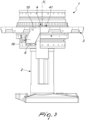
Figure 3 is a lateral elevation view of the machine part ofFigure 1 ; -
Figure 4 is a top plan view of the machine part ofFigure 1 ; -
Figure 5 is a perspective view of part of a second embodiment of a machine according to the invention; -
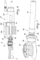
Figure 6 is a sectional side view of a detail ofFigure 5 ; -
Figure 7 is a perspective view of the detail of a transmission assembly of the machine ofFigure 5 ; -
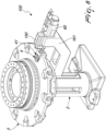
Figure 8 is a perspective view of part of a third embodiment of a machine not covered by the invention; -
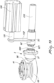
Figure 9 is a lateral sectional view of a detail ofFigure 8 ; -
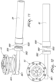
Figure 10 is a perspective view of the detail of the transmission assembly of the machine ofFigure 8 ; -
Figure 11 is a perspective view of a possible alternative embodiment of the transmission assembly of a machine according to the invention; -
Figure 12 is a top plan view ofFigure 11 ; -
Figure 13 is a sectional side view of a possible embodiment of the collet assembly of a machine according to the invention; -
Figure 14 is a top plan view of a possible embodiment of the indexing device of a machine according to the invention. - Before delving into the detailed description, it should be noted that the accompanying figures show parts of a machine tool according to the invention which, for the sake of clarity, have some parts removed (e.g., radial peripheral machining stations) since these parts, in addition to being known by the person skilled in the art, are not useful for the comprehension of the invention itself and would only contribute to an overall crowding of the figures.
- With reference to the cited figures, the improved transfer machine, designated generally by the
reference numerals frame 2 and a table 3 which is supported on saidframe 2 and can rotate with respect to it about a main vertical axis Y1. - Multiple mutually angularly spaced work holding
assemblies 4 are mounted on the table 3; preferably, the work holdingassemblies 4 are all extended on the same circumference. - Each
work holding assembly 4 is provided at least with onecollet assembly 41 for retaining a workpiece being machined; thecollet assembly 41 can rotate with respect to the table 3 about a vertical workpiece rotation axis Y2, so as to rotate the workpiece for the corresponding machining or positioning maneuvers. - In the illustrated examples, the table 3 is substantially circular and the work holding
assemblies 4 are distributed uniformly along the circumference of the table 3. - In other embodiments, the table 3 can have different shapes, such as for example a polygonal or lobate shape, with the work holding
assemblies 4 arranged according to the specific machining requirements. - The
machine actuation motor collet assembly 41 and provided with adriving shaft - In some embodiments the
machine 1 comprises anactuation motor dedicated collet assembly 41; in other embodiments, the machine comprises a plurality ofactuation motors collet assemblies 41; in some embodiments there are also collet assemblies which are not motorized or a motorized in a different manner; in still other embodiments there is an actuation motor which is common tomultiple collet assemblies 41. - For the sake of simplicity, hereinafter reference will be made to the preferred and illustrated embodiments, in which a
motor collet assembly 41. - In common to the various embodiments, the machine also comprises at least one selectively
activatable transmission assembly driving shaft motor collet assembly 41. - According to the invention, said at least one
actuation motor frame 2 of themachine respective driving shaft - In the preferred and illustrated embodiments, the
collet assemblies 41 define a work radius R of themachine actuation motor - In other words, as shown in
Figure 4 , thecollet assemblies 41 are preferably all arranged at a same distance R from the main vertical axis Y1, being therefore arranged along a circumference with a radius equal to said distance R, and themotor - As can be understood by looking at the figures, this solution allows to free space around the
collet assembly 41, especially toward the machine center, without having to increase the diameter of the table 3, even in the presence ofactuation motors 6 that have a large space occupation. - Furthermore, the
motor collet assembly 41, is less exposed to shavings and machining liquids (e.g., lubricating-refrigerating liquids and the like). - The
motor support Figures 8 and9 ) is coupled rigidly to the frame, in other embodiments (Figures 1 to 6 ) can be moved, with respect to theframe 2, along a rectilinear trajectory X2; these aspects will also be described hereinafter. - In greater detail, in the embodiments shown in
Figures 1 to 6 , themachine support frame 2 and more precisely can move along a rectilinear trajectory X2. - With reference to these
embodiments motor support motor driving shaft transmission assembly collet assembly 41 is functionally coupled to thedriving shaft transmission assembly collet assembly 41 is functionally uncoupled from thedriving shaft - In even greater detail, it is possible to recognize a first embodiment (
Figures 1 ,2 ,3 and4 ), in which themotor 6 is fixed internally with respect to the support 16 (i.e., on the part of thesupport 16 that is proximal with respect to the table 3), and a second embodiment (Figures 5 and6 ), in which themotor 60 is fixed to the outside of the support 160 (distally with respect to the table 3). - In this second embodiment, as shown in
Figure 6 , the support is provided with a perforated seat which is crossed by thedriving shaft 610 and inside which the drivingshaft 610 can rotate freely. - It should be noted that in this second embodiment, since the
support 160 is interposed between the table 3 and themotor 60, the latter is more protected during machining against shavings and work liquids. - In both of these two embodiments, the
machine actuator frame 2 and to themovable support frame 2. - Said
actuator 15 can be, for example, a hydraulic actuator (e.g., a hydraulic cylinder) which comprises a body which is coupled to the frame and an expandable piston which is connected to themovable support - In the illustrated example, the
actuator 150 is fixed on anarm 22, which in turn is fixed to theframe 2, the distal portion of which is interposed between themovable support 160 and the table 3. Said distal portion of thearm 22 is conveniently provided with a channel which is crossed by thedriving shaft 610 and inside which the drivingshaft 610 is free to rotate and slide longitudinally. - It should be noted that in both embodiments the movement trajectory X2 of the
support 16 lies on a horizontal plane which is perpendicular to the main vertical axis Y1. -
Figures 8 and9 show a third embodiment not covered by the claims, in which themachine 100 comprises asupport 161 which is coupled rigidly to theframe 2 and in which thedriving shaft 61 and thetransmission assembly 50 comprise a coupling which can be activated selectively in order to provide an activated transmission assembly condition, in which thecollet assembly 41 is functionally coupled to thedriving shaft 61, and a deactivated transmission assembly condition, in which thecollet assembly 41 is functionally uncoupled from thedriving shaft 61. - In the example shown in
Figures 8 and9 , thesupport 161 in practice is constituted by an arm with the same characteristics already described for thearm 22 that is present in the second embodiment. - The manners in which the activated and deactivated transmission assembly conditions are provided will become better apparent from the description of some possible embodiments of the
transmission assemblies -
Figures 6, 7 show in detail thetransmission assembly 50 of the second embodiment of themachine 10, i.e., the one shown inFigure 5 , in which thesupport -
Figures 9 and10 instead show the details related to thetransmission assembly 5 of the third embodiment of themachine 100, i.e., the one shown inFigure 8 , in which thesupport 161 is coupled rigidly to the frame. - In both of these embodiments, the
transmission assembly first bevel gear 55 with a vertical axis and asecond bevel gear 56 with a horizontal axis, which mesh together. - In greater detail, the
first gear 55 is integral with thecollet assembly 41 and thesecond gear 56 is integral with anengagement shaft 57 which is coaxial to the drivingshaft - The difference between the two embodiments resides in the mechanism with which the activated transmission assembly condition and the deactivated transmission assembly conditions are provided.
- In the first example, shown in
Figures 6 and 7 , theengagement shaft 57 and the drivingshaft 61 comprise facing toothed engagement ends 58, 68, which are configured to mesh in the activated transmission assembly condition; in these embodiments, the activated transmission assembly condition is provided by translating themotor shaft 61 that is integral therewith in the direction of the table 3 to the position in which thetoothed end 68 of the drivingshaft 61 meshes with thetoothed end 58 of theengagement shaft 57, thus providing a continuous kinematic chain between the drivingshaft 61 and thecollet assembly 41 so as to provide the latter with rotational actuation. - Vice versa, the deactivated transmission assembly condition is obtained by translating the
motor shaft 61 in the opposite direction. - The translation of the driving
shaft 61 and of themotor support actuator - According to an optional and advantageous characteristics, the
actuator 15 is configured to impart, in the activated transmission assembly condition, a preloading thrust to the drivingshaft 61 so as to minimize, to the point of substantially eliminating, plays between the drivingshaft 61 and theengagement shaft 57; this allows to improve the precision of the couplings and therefore the precision of the machining. - The solution that has just been described is used also in the first embodiment of the
machine 1 shown inFigures 1 and2 . - In the second example shown in
Figures 9 and10 , theengagement shaft 57 is provided with afree end 580 provided with engagement teeth, while the drivingshaft 610 comprises acoupling sleeve 62, which rotates integrally with the drivingshaft 61 and can be moved along the latter. In greater detail, thesleeve 62 is provided with atoothed engagement end 621 which faces thefree end 580 of theengagement shaft 57 in order to mesh with it in the activated transmission assembly condition; for the rotational coupling between thesleeve 62 and the drivingshaft 61 it is possible to provide, for example, grooves and radial teeth and or the like. - In practice, in this last embodiment, the
motor 60 and the drivingshaft 610 are fixed with respect to theframe 2 and the activated transmission assembly condition is provided by translating thesleeve 62 along the drivingshaft 610, in the direction of the table 3, to the position in which thetoothed engagement end 621 of thesleeve 62 meshes with the free end of the drivingshaft 57, thus providing a continuous kinematic chain between the drivingshaft 610 and thecollet assembly 41. - The
sleeve 62 is constituted for example by a substantially cylindrical body provided with a longitudinal cavity which is at least partly engaged by the drivingshaft 610. - Advantageously, multiple longitudinal teeth are provided on the side wall of said cavity and engage in a corresponding number of longitudinal grooves provided on the outer wall of the driving
shaft 610. In this manner the drivingshaft 610 and thesleeve 62 are rotationally coupled (i.e., the rotation of the drivingshaft 610 turns the sleeve 62) and at the same time thesleeve 62 is free to slide longitudinally along the drivingshaft 610. - The translation of the
sleeve 62 along the drivingshaft 610 is provided preferably by means of anactuator 150 which is fixed to thesame support 161 that supports themotor 60. - In greater detail, the
actuator 150 is provided with anexpandable piston 151, which moves along a rectilinear trajectory thesleeve 62 by means of acoupling bar 152. - The
coupling bar 152 comprises a first end which is rigidly coupled to thepiston 151 and a second end which engages an annular groove 63 provided on the external surface of thesleeve 62; the second end engages the annular groove 63 so as to not hinder the rotation of thesleeve 62. - Optionally, in a manner similar to what has been described above, the
actuator 150 is configured to apply a preloading thrust to thesleeve 62 in the activated transmission assembly condition. - In other possible embodiments, not shown, the
first bevel gear 55 with vertical axis, thesecond bevel gear 56 with horizontal axis and theengagement shaft 57 are replaced with one or more kinematic transmission elements of a different type, such as for example a gear-worm screw system. - For example,
Figure 11 shows thetransmission assembly 500 of another possible embodiment. In this example, thetransmission assembly 500 comprises agear 551 and aworm screw 561, which are coupled in rotation to thecollet assembly 41. - The
worm screw 561 in turn is provided with ahorizontal screw shaft 562, which is coaxial to the drivingshaft 61 and is configured to be coupled to the latter. - In greater detail, the
screw shaft 562 and the drivingshaft 61 comprise facing toothed engagement ends 560, 620 which are configured to mesh in the activated transmission assembly condition. - In practice, in this last embodiment, the activated transmission assembly condition is provided by translating the
motor shaft 61 that is integral therewith in the direction of the table 3 to the position in which thetoothed end 620 of the drivingshaft 61 meshes with thetoothed end 560 of thescrew shaft 562, thus providing a continuous kinematic chain between the drivingshaft 61 and thecollet assembly 41, in a manner similar to what has already been described for the first two embodiments of themachine - In yet another embodiment (not shown), the
transmission assembly 500 comprises agear 551 and aworm screw 561 which are rotationally coupled to thecollet assembly 41 and ascrew shaft 562 which is coaxial to the drivingshaft 61; thescrew shaft 562 is provided with a free end equipped with engagement teeth and the drivingshaft 61 comprises a coupling sleeve, which rotates integrally with the drivingshaft 61 and can be moved along it. - Said sleeve, exactly like the one of
Figure 10 already described, is provided with a toothed engagement end which faces the free end of the screw shaft in order to mesh together in the activated transmission assembly condition. - In practice, in this last embodiment, the
motor 60 and the driving shaft are fixed with respect to theframe 2 and the activated transmission assembly condition is provided by translating thesleeve 62 along the drivingshaft 61, in the direction of the table 3, to the position in which thetoothed engagement end 621 of thesleeve 62 meshes with the free end of theengagement shaft 57, thus providing a continuous kinematic chain between the drivingshaft 61 and thecollet assembly 41, in a manner similar to what has already been described for the third embodiment of themachine 100 ofFigure 8 . -
Figure 13 shows a preferred embodiment of thecollet assembly 41; in this embodiment, thecollet assembly 41 comprises ahollow body 411, which is preferably cylindrical, and anexternal shaft 415, which is also hollow, is coaxial to thehollow body 411 and is functionally coupled to thetransmission assembly - Even more preferably, the
external shaft 415 has a cylindrical shape and is open at both longitudinal ends like a tube. - Again with reference to the example shown in
Figure 13 , the hollow body 411 (generally termed work holding collet) is locked in the cavity of theexternal shaft 415 so as to rotate integrally therewith. - In practice, the
external shaft 415 is rigidly coupled to thehollow body 411 so as to rotate it about the vertical workpiece rotation axis Y2. - The
hollow body 411 is provided with an access opening 43 for atool 92 and withelements 44 for retaining the workpiece being machined. - In other words, a cavity that can be accessed by the
tool 92 through saidopening 43 is advantageously formed between theretention elements 44 and theopening 43; it should be noted that in this manner the part being machined is accessible for machining from both sides, from above and from below. - In even greater detail, the
retention elements 44 are constituted for example by contoured and appropriately machined edges of a through hole (preferably a ground cylindrical hole) which is provided on the end face of thehollow body 41 and more precisely on the end face that lies opposite theopening 43. These edges, by moving mutually closer, reduce the aperture of the through hole, tightening around the workpiece being machined. - The mutual radial movement of the retention elements is preferably made possible by the fact that the
hollow body 41 is divided longitudinally into movable circular sectors which in practice constitute a plurality of claws or jaws. - The movement of these circular sectors is induced by one or
more wedges 46 which are arranged between the internal wall of theexternal shaft shaft 45 and the external wall of thehollow body 41. - Preferably, there is a
single wedge 46 which is constituted by a tubular body with a substantially frustum-like external shape and is provided with an axial through cavity inside which thehollow body 411 can be accommodated. - In practice, by inserting the wedge (or the wedges) 46 in the space between the
hollow body 41 and theexternal shaft 45, the circular sectors of thehollow body 411 are pushed radially closer, reducing the aperture of the through hole and clamping theretention elements 44 around the workpiece. - In other embodiments, the
retention elements 44 are provided with adapted grip elements, such as for example metallic or plastic plates, teeth, clamps, etc. - In the illustrated example, the
work holding assembly 4 also comprises a plurality ofbearings 49, such as for example ball bearings, which surround thecollet assembly 41, facilitating its correct rotation. - Preferably, the
transfer machine 1 furthermore comprises at least one machining station (not shown) which is supported by the frame and is provided at least with one working head functionally connected to a tool; the machining station comprises - in a fully general manner - the tool and the means required to move/actuate it (e.g., drive unit). - In some preferred solutions, the machining station comprises three working heads: an upper head arranged at a higher level than the table, a lower head arranged at a lower level than the table, and an intermediate head arranged substantially at a level that is intermediate between the two, so as to be able to perform machinings of the workpiece from three directions if required.
- In this preferred embodiment, the actuation motor is preferably arranged at a lower level than the lower head.
- At this point it is useful to specify that the term tool used up to now is understood to reference in a fully general manner any implement that is useful to perform machinings on a workpiece.
- Preferably, these tools comprise implements for mechanical machining, particularly by chip forming, such as for example cutters, bits, cutting or shaping taps, rolling tools, broaching tools, punches, different turning tools, etc.
- However, embodiments are also possible in which the tools used are of another type, such as for example laser emission heads or pressurized fluid emission heads.
- According to an optional and advantageous characteristic, the
machine collet assembly 41 and the table 3 and is configured to provide an indexing of thecollet assembly 41, i.e., the radial placement of the collet in a preset position, so as to orient the workpiece in an appropriate and repeatable manner. - Preferably, an indexing device is present for each
collet assembly 41. - The term "indexing" is understood to reference the unique determination of the placement in a given angular position.
- In practice, the indexing device allows to fix the collet assembly 40 (and therefore the workpiece with it) with a given orientation, locking the rotation of the
collet assembly 41 and thus keeping the workpiece stationary in this position. - In this way precision machinings are possible in an automated manner.
- One of the possible embodiments of the indexing device is shown in
Figure 14 . - In the illustrated example, the indexing device 7 comprises an
annular body 71 which is coupled rigidly to theexternal shaft 45 of thecollet assembly 41 and is preferably keyed to the outside thereof, so as to rotate integrally therewith about the same workpiece rotation axis Y2. - The
annular body 71 is provided, along its external wall, with one or more perimetric reference hollows 73, 73'. - The preferred and illustrated indexing device 7 furthermore comprises a locking
arm 72 which can oscillate and is provided with at least onepivot 74 which is configured to engage the reference hollow 73, 73' when the latter is in a preset position (which faces thepivot 74 in the preferred and illustrated embodiment). - In greater detail, the
detection arm 72 is pivoted, at a first end, to a surface of the table 3 and, at a second end, is connected to a return element 75 (such as for example an elastic element, such as a spring), which pulls thearm 72 in rotation toward theannular body 71, thus pushing thepivot 74 to engage the reference hollow 73 when it is aligned with saidpivot 74. - Proximate to the second end of the
detection arm 72 there is aswitch 77 or a sensor (such as for example an inductive or capacitive sensor) which, by detecting the position of thedetection arm 72, indirectly detects that indexing has occurred (i.e., that thecollet assembly 41 has been fixed in the predetermined position). - The indexing device is particularly useful for drilling and milling work and therefore is preferably adopted in transfer machines intended for this type of machining.
- As is obvious, the
transfer machine 1 preferably also comprises a driving assembly and a transmission system for the rotation of the table 3, as well as control electronics; these elements are per se known and therefore are not described in further detail. - The operation of the improved transfer machine is clear and evident from what has been described.
- In practice it has been found that the improved transfer machine according to the present invention achieves the intended aim and objects, since it allows to have available a solution that allows the mounting of motors of any size and power without the dimensions and/or the space occupations of the table being affected.
- Another advantage of the transfer machine according to the invention resides in that it is less sensitive to dirt and/or fragments caused by machining.
- A further advantage of the transfer machine according to the invention resides in that it provides an alternative to known solutions.
- Another advantage of the transfer machine according to the invention resides in that it has a facilitated maintenance.
- In practice, the materials used, so long as they are compatible with the specific use, as well as the contingent shapes and dimensions, may be any according to the requirements.
Claims (7)
- A transfer machine (1, 10, 100) comprising:- a frame (2),- a table (3) which is supported on the frame (2) and can rotate with respect to the frame (2) about a main vertical axis (Y1),- a plurality of work holding assemblies (4) mounted on the table (3), each work holding assembly (4) being provided with at least one collet assembly (41) for retaining a workpiece being machined, said collet assembly (41) being able to rotate with respect to the table (3) about a vertical workpiece rotation axis (Y2),- at least one actuation motor (6, 60) in order to actuate rotationally said collet assembly (41) and provided with a driving shaft (61, 610) which can rotate about a respective driving axis,- at least one transmission assembly (5, 50), which can be activated selectively and is configured to transmit motion from said driving shaft (61, 610) to said collet assembly (41),wherein said at least one actuation motor (6, 60) is integral with the frame (2) of the machine,
characterized in that the respective driving shaft (61, 610) of said at least one actuation motor (6, 60) is arranged horizontally,and in that
said machine (1, 10) comprises a support (16, 160) which is movably coupled to the frame (2), said support (16, 160) being movable along a rectilinear trajectory (X2), the motor (6, 60) being integral with the support (16, 160), at least the motor (6, 60) and the driving shaft (61) being movable in a linear manner between a condition in which the transmission assembly (5, 50) is activated, in which the collet assembly (41) is functionally coupled to the driving shaft (6, 60), and a condition in which the transmission assembly (50) is deactivated, in which the collet assembly (41) is functionally uncoupled from the driving shaft (61); the machine (1, 10) furthermore comprises an actuator (15, 150) which is coupled to the frame (2) and to the movable support (16, 160) in order to actuate the rectilinear movement of the latter with respect to the frame (2), the movement trajectory (X2) of the support (16) lying on a horizontal plane which is perpendicular with respect to the main vertical axis (Y1). - The machine (1, 10, 100) according to claim 1, wherein said collet assemblies (41) define a work radius (R) of the machine (1, 10, 100), said at least one actuation motor (6, 60) being mounted externally to said work radius (R).
- The machine according to one of the preceding claims, wherein the transmission assembly (5, 50) comprises a first bevel gear (55) with vertical axis and a second bevel gear (56) with horizontal axis, which mesh together, and wherein the first gear (55) is integral with the collet assembly (41) and the second gear (56) is integral with an an engagement shaft (57) configured to be coupled to the driving shaft (61, 610).
- The machine according to claim 3, wherein the engagement shaft (57) is coaxial to the driving shaft (61), the engagement shaft (57) and the driving shaft (61, 610) comprise toothed engagement ends (58, 68) which are configured to mesh in the activated transmission assembly condition.
- The machine according to one of the preceding claims, wherein the transmission assembly (500) comprises a gear (551) and a worm screw (561) which are coupled rotationally to said collet assembly (41), the worm screw (561) being provided with a horizontal screw shaft (562), said screw shaft (562) being configured to be coupled to the driving shaft (61).
- The machine according to claim 5, wherein the screw shaft (562) is coaxial to the driving shaft (61), the screw shaft (562) and the driving shaft (61) comprising facing toothed engagement ends (560, 620) which are configured to mesh in the activated transmission assembly condition.
- The machine according to one of the preceding claims, comprising an indexing device (7) which acts between the collet assembly (41) and the work holding table (3) configured to provide an indexing of the collet assembly (41).
Applications Claiming Priority (1)
| Application Number | Priority Date | Filing Date | Title |
|---|---|---|---|
| PCT/IB2018/050878 WO2019158965A1 (en) | 2018-02-13 | 2018-02-13 | Improved transfer machine |
Publications (3)
| Publication Number | Publication Date |
|---|---|
| EP3752320A1 EP3752320A1 (en) | 2020-12-23 |
| EP3752320C0 EP3752320C0 (en) | 2023-11-08 |
| EP3752320B1 true EP3752320B1 (en) | 2023-11-08 |
Family
ID=61764053
Family Applications (1)
| Application Number | Title | Priority Date | Filing Date |
|---|---|---|---|
| EP18713005.9A Active EP3752320B1 (en) | 2018-02-13 | 2018-02-13 | Improved transfer machine |
Country Status (4)
| Country | Link |
|---|---|
| US (1) | US11931839B2 (en) |
| EP (1) | EP3752320B1 (en) |
| CN (1) | CN111526969B (en) |
| WO (1) | WO2019158965A1 (en) |
Families Citing this family (3)
| Publication number | Priority date | Publication date | Assignee | Title |
|---|---|---|---|---|
| US12005538B2 (en) * | 2020-07-28 | 2024-06-11 | The Boeing Company | Methods and systems for supporting and positioning mechanical components or tools |
| CN115319008B (en) * | 2022-07-11 | 2025-03-07 | 来安县隆华摩擦材料有限公司 | Automatic plate loading machine for manufacturing friction plates |
| CN115534131B (en) * | 2022-10-13 | 2024-06-25 | 石家庄隆达金刚石制品有限公司 | Parallel working type diamond circular saw cutting device based on coaxial connection |
Family Cites Families (8)
| Publication number | Priority date | Publication date | Assignee | Title |
|---|---|---|---|---|
| US2965208A (en) | 1957-08-29 | 1960-12-20 | Motch Merryweather Machinery | Multi-station live spindle indexing machine |
| GB1234268A (en) | 1968-11-14 | 1971-06-03 | ||
| IT1175957B (en) * | 1984-03-09 | 1987-08-12 | Cucchi Flli | METAL BAR FORWARD CONTROL DEVICE FOR FEEDING AN AUTOMATIC LATHE WITH MULTIPLE SPINDLES |
| US5009296A (en) * | 1986-12-24 | 1991-04-23 | Tokyo Seat Co., Ltd. | Power transmitting apparatus for use in vehicle |
| DE19533320C2 (en) | 1995-09-08 | 1999-01-28 | Ottobeurer Facondreherei Alois | Rotary transfer machine |
| ITTO20121148A1 (en) | 2012-12-27 | 2014-06-28 | Siecab S R L | VERTICAL LATHE WITH MOBILE PICK-UP SPINDLE ALONG A CIRCULAR PATTERN |
| US9248546B1 (en) * | 2014-09-26 | 2016-02-02 | Engineered Abrasives, Inc. | Idler assembly for part processing |
| ES2937165T3 (en) * | 2016-04-18 | 2023-03-24 | Mikron Switzerland Ag Zweigniederlassung Agno Machining | Transfer machine with a rotary table |
-
2018
- 2018-02-13 WO PCT/IB2018/050878 patent/WO2019158965A1/en not_active Ceased
- 2018-02-13 US US16/957,521 patent/US11931839B2/en active Active
- 2018-02-13 EP EP18713005.9A patent/EP3752320B1/en active Active
- 2018-02-13 CN CN201880084882.0A patent/CN111526969B/en active Active
Also Published As
| Publication number | Publication date |
|---|---|
| WO2019158965A1 (en) | 2019-08-22 |
| EP3752320A1 (en) | 2020-12-23 |
| CN111526969B (en) | 2022-04-19 |
| US11931839B2 (en) | 2024-03-19 |
| CN111526969A (en) | 2020-08-11 |
| US20210053166A1 (en) | 2021-02-25 |
| EP3752320C0 (en) | 2023-11-08 |
Similar Documents
| Publication | Publication Date | Title |
|---|---|---|
| US4090281A (en) | Machine tool with multiple tool turret | |
| US11931839B2 (en) | Transfer machine | |
| CN110549166B (en) | Multifunctional movable beam combined machining center for turning, milling, grinding, boring and drilling | |
| US20040049902A1 (en) | Machine tool and method for machining | |
| US20050091812A1 (en) | Machining center | |
| JP2019520223A (en) | Workpiece rotation table | |
| KR101752905B1 (en) | Cutting apparatus | |
| KR101999424B1 (en) | Moving device of chuck jaw for lathe | |
| EP3319746B1 (en) | Pipe end machining device | |
| KR100427015B1 (en) | A turret device of machine tools | |
| JP5589645B2 (en) | Workpiece machining method and machining center | |
| KR102374067B1 (en) | Universal head units for machine tools | |
| KR20160107953A (en) | Electrically Driven Turret System and Method for Working the System | |
| CN214237070U (en) | Pipe fitting machining device | |
| KR101887449B1 (en) | A clamping device for a turning tool of machining center | |
| EP1724038B1 (en) | Portable lathe | |
| EP0556226B1 (en) | Improvements in or relating to machine tools | |
| CN219425716U (en) | Multidirectional drilling device | |
| JP4488775B2 (en) | Rotating table of machine tool | |
| KR102105719B1 (en) | Universal head attachment for machine tool | |
| CN114505706B (en) | Automatic locking device for double-sided machine tool spindle clamp | |
| JP2016043420A (en) | Table for machine tool | |
| KR100579073B1 (en) | Z-axis indexer of multi-task machine | |
| CN216421086U (en) | Indexing positioning device of middle-driven bidirectional clamping spindle box | |
| JP4494921B2 (en) | Grinder |
Legal Events
| Date | Code | Title | Description |
|---|---|---|---|
| STAA | Information on the status of an ep patent application or granted ep patent |
Free format text: STATUS: UNKNOWN |
|
| STAA | Information on the status of an ep patent application or granted ep patent |
Free format text: STATUS: THE INTERNATIONAL PUBLICATION HAS BEEN MADE |
|
| PUAI | Public reference made under article 153(3) epc to a published international application that has entered the european phase |
Free format text: ORIGINAL CODE: 0009012 |
|
| STAA | Information on the status of an ep patent application or granted ep patent |
Free format text: STATUS: REQUEST FOR EXAMINATION WAS MADE |
|
| 17P | Request for examination filed |
Effective date: 20200820 |
|
| AK | Designated contracting states |
Kind code of ref document: A1 Designated state(s): AL AT BE BG CH CY CZ DE DK EE ES FI FR GB GR HR HU IE IS IT LI LT LU LV MC MK MT NL NO PL PT RO RS SE SI SK SM TR |
|
| AX | Request for extension of the european patent |
Extension state: BA ME |
|
| DAV | Request for validation of the european patent (deleted) | ||
| DAX | Request for extension of the european patent (deleted) | ||
| RAP1 | Party data changed (applicant data changed or rights of an application transferred) |
Owner name: MIKRON SWITZERLAND AG, ZWEIGNIEDERLASSUNG AGNO, MACHINING |
|
| GRAP | Despatch of communication of intention to grant a patent |
Free format text: ORIGINAL CODE: EPIDOSNIGR1 |
|
| STAA | Information on the status of an ep patent application or granted ep patent |
Free format text: STATUS: GRANT OF PATENT IS INTENDED |
|
| INTG | Intention to grant announced |
Effective date: 20230602 |
|
| GRAS | Grant fee paid |
Free format text: ORIGINAL CODE: EPIDOSNIGR3 |
|
| GRAA | (expected) grant |
Free format text: ORIGINAL CODE: 0009210 |
|
| STAA | Information on the status of an ep patent application or granted ep patent |
Free format text: STATUS: THE PATENT HAS BEEN GRANTED |
|
| AK | Designated contracting states |
Kind code of ref document: B1 Designated state(s): AL AT BE BG CH CY CZ DE DK EE ES FI FR GB GR HR HU IE IS IT LI LT LU LV MC MK MT NL NO PL PT RO RS SE SI SK SM TR |
|
| REG | Reference to a national code |
Ref country code: GB Ref legal event code: FG4D |
|
| REG | Reference to a national code |
Ref country code: CH Ref legal event code: EP |
|
| REG | Reference to a national code |
Ref country code: DE Ref legal event code: R096 Ref document number: 602018060761 Country of ref document: DE |
|
| REG | Reference to a national code |
Ref country code: IE Ref legal event code: FG4D |
|
| U01 | Request for unitary effect filed |
Effective date: 20231201 |
|
| U07 | Unitary effect registered |
Designated state(s): AT BE BG DE DK EE FI FR IT LT LU LV MT NL PT SE SI Effective date: 20231207 |
|
| U20 | Renewal fee for the european patent with unitary effect paid |
Year of fee payment: 7 Effective date: 20240220 |
|
| PG25 | Lapsed in a contracting state [announced via postgrant information from national office to epo] |
Ref country code: GR Free format text: LAPSE BECAUSE OF FAILURE TO SUBMIT A TRANSLATION OF THE DESCRIPTION OR TO PAY THE FEE WITHIN THE PRESCRIBED TIME-LIMIT Effective date: 20240209 |
|
| PG25 | Lapsed in a contracting state [announced via postgrant information from national office to epo] |
Ref country code: IS Free format text: LAPSE BECAUSE OF FAILURE TO SUBMIT A TRANSLATION OF THE DESCRIPTION OR TO PAY THE FEE WITHIN THE PRESCRIBED TIME-LIMIT Effective date: 20240308 |
|
| PG25 | Lapsed in a contracting state [announced via postgrant information from national office to epo] |
Ref country code: ES Free format text: LAPSE BECAUSE OF FAILURE TO SUBMIT A TRANSLATION OF THE DESCRIPTION OR TO PAY THE FEE WITHIN THE PRESCRIBED TIME-LIMIT Effective date: 20231108 |
|
| PG25 | Lapsed in a contracting state [announced via postgrant information from national office to epo] |
Ref country code: IS Free format text: LAPSE BECAUSE OF FAILURE TO SUBMIT A TRANSLATION OF THE DESCRIPTION OR TO PAY THE FEE WITHIN THE PRESCRIBED TIME-LIMIT Effective date: 20240308 Ref country code: GR Free format text: LAPSE BECAUSE OF FAILURE TO SUBMIT A TRANSLATION OF THE DESCRIPTION OR TO PAY THE FEE WITHIN THE PRESCRIBED TIME-LIMIT Effective date: 20240209 Ref country code: ES Free format text: LAPSE BECAUSE OF FAILURE TO SUBMIT A TRANSLATION OF THE DESCRIPTION OR TO PAY THE FEE WITHIN THE PRESCRIBED TIME-LIMIT Effective date: 20231108 |
|
| PG25 | Lapsed in a contracting state [announced via postgrant information from national office to epo] |
Ref country code: RS Free format text: LAPSE BECAUSE OF FAILURE TO SUBMIT A TRANSLATION OF THE DESCRIPTION OR TO PAY THE FEE WITHIN THE PRESCRIBED TIME-LIMIT Effective date: 20231108 Ref country code: PL Free format text: LAPSE BECAUSE OF FAILURE TO SUBMIT A TRANSLATION OF THE DESCRIPTION OR TO PAY THE FEE WITHIN THE PRESCRIBED TIME-LIMIT Effective date: 20231108 Ref country code: NO Free format text: LAPSE BECAUSE OF FAILURE TO SUBMIT A TRANSLATION OF THE DESCRIPTION OR TO PAY THE FEE WITHIN THE PRESCRIBED TIME-LIMIT Effective date: 20240208 Ref country code: HR Free format text: LAPSE BECAUSE OF FAILURE TO SUBMIT A TRANSLATION OF THE DESCRIPTION OR TO PAY THE FEE WITHIN THE PRESCRIBED TIME-LIMIT Effective date: 20231108 |
|
| PG25 | Lapsed in a contracting state [announced via postgrant information from national office to epo] |
Ref country code: CZ Free format text: LAPSE BECAUSE OF FAILURE TO SUBMIT A TRANSLATION OF THE DESCRIPTION OR TO PAY THE FEE WITHIN THE PRESCRIBED TIME-LIMIT Effective date: 20231108 |
|
| PG25 | Lapsed in a contracting state [announced via postgrant information from national office to epo] |
Ref country code: SK Free format text: LAPSE BECAUSE OF FAILURE TO SUBMIT A TRANSLATION OF THE DESCRIPTION OR TO PAY THE FEE WITHIN THE PRESCRIBED TIME-LIMIT Effective date: 20231108 |
|
| PG25 | Lapsed in a contracting state [announced via postgrant information from national office to epo] |
Ref country code: SM Free format text: LAPSE BECAUSE OF FAILURE TO SUBMIT A TRANSLATION OF THE DESCRIPTION OR TO PAY THE FEE WITHIN THE PRESCRIBED TIME-LIMIT Effective date: 20231108 Ref country code: SK Free format text: LAPSE BECAUSE OF FAILURE TO SUBMIT A TRANSLATION OF THE DESCRIPTION OR TO PAY THE FEE WITHIN THE PRESCRIBED TIME-LIMIT Effective date: 20231108 Ref country code: RO Free format text: LAPSE BECAUSE OF FAILURE TO SUBMIT A TRANSLATION OF THE DESCRIPTION OR TO PAY THE FEE WITHIN THE PRESCRIBED TIME-LIMIT Effective date: 20231108 Ref country code: CZ Free format text: LAPSE BECAUSE OF FAILURE TO SUBMIT A TRANSLATION OF THE DESCRIPTION OR TO PAY THE FEE WITHIN THE PRESCRIBED TIME-LIMIT Effective date: 20231108 |
|
| REG | Reference to a national code |
Ref country code: DE Ref legal event code: R097 Ref document number: 602018060761 Country of ref document: DE |
|
| PLBE | No opposition filed within time limit |
Free format text: ORIGINAL CODE: 0009261 |
|
| STAA | Information on the status of an ep patent application or granted ep patent |
Free format text: STATUS: NO OPPOSITION FILED WITHIN TIME LIMIT |
|
| PG25 | Lapsed in a contracting state [announced via postgrant information from national office to epo] |
Ref country code: MC Free format text: LAPSE BECAUSE OF FAILURE TO SUBMIT A TRANSLATION OF THE DESCRIPTION OR TO PAY THE FEE WITHIN THE PRESCRIBED TIME-LIMIT Effective date: 20231108 |
|
| REG | Reference to a national code |
Ref country code: CH Ref legal event code: PL |
|
| 26N | No opposition filed |
Effective date: 20240809 |
|
| PG25 | Lapsed in a contracting state [announced via postgrant information from national office to epo] |
Ref country code: CH Free format text: LAPSE BECAUSE OF NON-PAYMENT OF DUE FEES Effective date: 20240229 |
|
| GBPC | Gb: european patent ceased through non-payment of renewal fee |
Effective date: 20240213 |
|
| PG25 | Lapsed in a contracting state [announced via postgrant information from national office to epo] |
Ref country code: CH Free format text: LAPSE BECAUSE OF NON-PAYMENT OF DUE FEES Effective date: 20240229 |
|
| PG25 | Lapsed in a contracting state [announced via postgrant information from national office to epo] |
Ref country code: GB Free format text: LAPSE BECAUSE OF NON-PAYMENT OF DUE FEES Effective date: 20240213 |
|
| PG25 | Lapsed in a contracting state [announced via postgrant information from national office to epo] |
Ref country code: IE Free format text: LAPSE BECAUSE OF NON-PAYMENT OF DUE FEES Effective date: 20240213 |
|
| PG25 | Lapsed in a contracting state [announced via postgrant information from national office to epo] |
Ref country code: IE Free format text: LAPSE BECAUSE OF NON-PAYMENT OF DUE FEES Effective date: 20240213 Ref country code: GB Free format text: LAPSE BECAUSE OF NON-PAYMENT OF DUE FEES Effective date: 20240213 Ref country code: CH Free format text: LAPSE BECAUSE OF NON-PAYMENT OF DUE FEES Effective date: 20240229 |
|
| PGRI | Patent reinstated in contracting state [announced from national office to epo] |
Ref country code: CH Effective date: 20241028 |
|
| U20 | Renewal fee for the european patent with unitary effect paid |
Year of fee payment: 8 Effective date: 20250220 |
|
| PG25 | Lapsed in a contracting state [announced via postgrant information from national office to epo] |
Ref country code: CY Free format text: LAPSE BECAUSE OF FAILURE TO SUBMIT A TRANSLATION OF THE DESCRIPTION OR TO PAY THE FEE WITHIN THE PRESCRIBED TIME-LIMIT; INVALID AB INITIO Effective date: 20180213 |
|
| PG25 | Lapsed in a contracting state [announced via postgrant information from national office to epo] |
Ref country code: HU Free format text: LAPSE BECAUSE OF FAILURE TO SUBMIT A TRANSLATION OF THE DESCRIPTION OR TO PAY THE FEE WITHIN THE PRESCRIBED TIME-LIMIT; INVALID AB INITIO Effective date: 20180213 |
|
| PG25 | Lapsed in a contracting state [announced via postgrant information from national office to epo] |
Ref country code: TR Free format text: LAPSE BECAUSE OF FAILURE TO SUBMIT A TRANSLATION OF THE DESCRIPTION OR TO PAY THE FEE WITHIN THE PRESCRIBED TIME-LIMIT Effective date: 20231108 |
|
| REG | Reference to a national code |
Ref country code: CH Ref legal event code: U11 Free format text: ST27 STATUS EVENT CODE: U-0-0-U10-U11 (AS PROVIDED BY THE NATIONAL OFFICE) Effective date: 20260330 |
|
| U20 | Renewal fee for the european patent with unitary effect paid |
Year of fee payment: 9 Effective date: 20260220 |
|
| PGFP | Annual fee paid to national office [announced via postgrant information from national office to epo] |
Ref country code: CH Payment date: 20260330 Year of fee payment: 9 |