EP3752233B1 - Tube assembly and dissolvable tip - Google Patents
Tube assembly and dissolvable tip Download PDFInfo
- Publication number
- EP3752233B1 EP3752233B1 EP19754912.4A EP19754912A EP3752233B1 EP 3752233 B1 EP3752233 B1 EP 3752233B1 EP 19754912 A EP19754912 A EP 19754912A EP 3752233 B1 EP3752233 B1 EP 3752233B1
- Authority
- EP
- European Patent Office
- Prior art keywords
- tube
- tip
- tube assembly
- dissolvable
- vent
- Prior art date
- Legal status (The legal status is an assumption and is not a legal conclusion. Google has not performed a legal analysis and makes no representation as to the accuracy of the status listed.)
- Active
Links
Images

Classifications
-
- A—HUMAN NECESSITIES
- A61—MEDICAL OR VETERINARY SCIENCE; HYGIENE
- A61J—CONTAINERS SPECIALLY ADAPTED FOR MEDICAL OR PHARMACEUTICAL PURPOSES; DEVICES OR METHODS SPECIALLY ADAPTED FOR BRINGING PHARMACEUTICAL PRODUCTS INTO PARTICULAR PHYSICAL OR ADMINISTERING FORMS; DEVICES FOR ADMINISTERING FOOD OR MEDICINES ORALLY; BABY COMFORTERS; DEVICES FOR RECEIVING SPITTLE
- A61J15/00—Feeding-tubes for therapeutic purposes
- A61J15/0026—Parts, details or accessories for feeding-tubes
-
- A—HUMAN NECESSITIES
- A61—MEDICAL OR VETERINARY SCIENCE; HYGIENE
- A61J—CONTAINERS SPECIALLY ADAPTED FOR MEDICAL OR PHARMACEUTICAL PURPOSES; DEVICES OR METHODS SPECIALLY ADAPTED FOR BRINGING PHARMACEUTICAL PRODUCTS INTO PARTICULAR PHYSICAL OR ADMINISTERING FORMS; DEVICES FOR ADMINISTERING FOOD OR MEDICINES ORALLY; BABY COMFORTERS; DEVICES FOR RECEIVING SPITTLE
- A61J15/00—Feeding-tubes for therapeutic purposes
- A61J15/0003—Nasal or oral feeding-tubes, e.g. tube entering body through nose or mouth
- A61J15/0007—Nasal or oral feeding-tubes, e.g. tube entering body through nose or mouth inserted by using a guide-wire
-
- A—HUMAN NECESSITIES
- A61—MEDICAL OR VETERINARY SCIENCE; HYGIENE
- A61J—CONTAINERS SPECIALLY ADAPTED FOR MEDICAL OR PHARMACEUTICAL PURPOSES; DEVICES OR METHODS SPECIALLY ADAPTED FOR BRINGING PHARMACEUTICAL PRODUCTS INTO PARTICULAR PHYSICAL OR ADMINISTERING FORMS; DEVICES FOR ADMINISTERING FOOD OR MEDICINES ORALLY; BABY COMFORTERS; DEVICES FOR RECEIVING SPITTLE
- A61J15/00—Feeding-tubes for therapeutic purposes
- A61J15/0026—Parts, details or accessories for feeding-tubes
- A61J15/0096—Provisions for venting
-
- A—HUMAN NECESSITIES
- A61—MEDICAL OR VETERINARY SCIENCE; HYGIENE
- A61M—DEVICES FOR INTRODUCING MEDIA INTO, OR ONTO, THE BODY; DEVICES FOR TRANSDUCING BODY MEDIA OR FOR TAKING MEDIA FROM THE BODY; DEVICES FOR PRODUCING OR ENDING SLEEP OR STUPOR
- A61M25/00—Catheters; Hollow probes
- A61M25/0067—Catheters; Hollow probes characterised by the distal end, e.g. tips
- A61M25/0068—Static characteristics of the catheter tip, e.g. shape, atraumatic tip, curved tip or tip structure
- A61M25/0069—Tip not integral with tube
-
- A—HUMAN NECESSITIES
- A61—MEDICAL OR VETERINARY SCIENCE; HYGIENE
- A61M—DEVICES FOR INTRODUCING MEDIA INTO, OR ONTO, THE BODY; DEVICES FOR TRANSDUCING BODY MEDIA OR FOR TAKING MEDIA FROM THE BODY; DEVICES FOR PRODUCING OR ENDING SLEEP OR STUPOR
- A61M25/00—Catheters; Hollow probes
- A61M25/01—Introducing, guiding, advancing, emplacing or holding catheters
Definitions
- This document relates generally to temporary tubes for placement in a patient, and more specifically with tips used therewith.
- Tips facilitate insertion by having an arcuate shape along at least a portion of an outer surface.
- the outer surface may have a rounded or bullet shaped distal portion which enhances gliding and bending along curved, fragile surfaces of the nasal airway, the pharynx, the esophagus, stomach and/or intestines for example.
- a tip designed to facilitate insertion could prevent unobstructed flow of material(s) passing out of the end of the tube.
- a partial or complete change away from axial material or fluid flow is required to exit via a pathway around or through the tip. Due to this necessary change of direction, the tip may interfere with such flow and thus contribute to complications associated with the tube, for example, clogging.
- Document WO2017007829 discloses a tube for placement within a patient, the tube having a lumen increasing in diameter along at least a portion of the tube to a distal end.
- a tube assembly is provided.
- the tube assembly may be broadly described as including a tube for placement within a patient.
- the tube includes a lumen, a proximal end portion, and a distal end portion attached to a dissolvable tip.
- the invention is defined by the appended claims.
- the tip is partially inserted into the lumen within the distal end portion.
- the tip includes a proximal end portion for insertion into the tube is less pliable than the tube.
- the proximal end portion of the tip includes at least one of a ridge or a ring.
- the tip includes a central aperture. In still another, the tip is solid.
- the tip includes an outer coating.
- the outer coating is a water activated lubricious coating.
- the tip includes at least one vent.
- an outer diameter of the tube and an outer diameter of the tip are substantially the same.
- the tip includes a conical or bullet-shaped distal end.
- the tube includes at least one vent.
- the tip includes at least one vent and the tube includes at least one corresponding vent.
- the tip includes a collar that extends through the tube vent.
- a tube assembly in another possible example, includes a tube for placement within a patient and a tip attached to a distal end portion of the tube.
- the tip is formed from a material dissolvable in a fluid.
- an enteral tube for placement within a patient includes a lumen and a distal end portion having an orifice therein, and a tip inserted into the lumen at a distal end of the tube, the tip having an angled face for directed matter out of the orifice.
- a tip for use with a tube for placement within a patient includes a distal end for insertion into the patient, and a proximal end for engaging the tube wherein at least the proximal end comprises a soluble material.
- an of the tip comprises a soluble material.
- the soluble material is any material or combination of materials which are soluble and suitable for human or animal consumption.
- the soluble material is a polymer.
- the tube is an enteral tube which includes, but is not limited to, nasogastric tubes, nasoduodenal tubes, oral gastric tubes, oral duodenal tube, and feeding tubes located distal to the duodenum.
- enteral tube which includes, but is not limited to, nasogastric tubes, nasoduodenal tubes, oral gastric tubes, oral duodenal tube, and feeding tubes located distal to the duodenum.
- Other embodiments may utilize other types of tubes, for example, gastrostomy or G-tubes inserted through the patient's abdomen to deliver nutrition directly to the stomach. While some designs utilize a bolster system designed to prevent withdrawal of the gastrostomy tube, others utilize other anchor means (e.g., inflatable balloons) to prevent withdrawal.
- anchor means e.g., inflatable balloons
- a dissolvable tip may be utilized to improve the insertion process by limiting patient discomfort while ultimately allowing for the free flow of nutrients through the tube.
- One family of such gastrostomy devices is marketed under the brand MiniONE ® including balloon and non-balloon devices.
- a tube assembly 10 includes the enteral tube, or tube 12, and a tip 14.
- the tube 12 includes a lumen extending a length of the tube from a proximal end portion (not shown) to a distal end portion 18 having an orifice therein.
- the described tip 14 defines a vent 20 and a distal aperture 22 for a guidewire (not shown) to pass through if desired.
- a square or butt connection between the tube 12 and tip 14 is shown with a proximal portion of the tip being hidden from view and positioned within the tube in this figure. As described below, other methods of attaching the tip 14 to the tube 12 may be utilized.
- the tip 14 Since the tip 14 is only useful during tube insertion, the tip is made of a dissolvable material. In other words, the tip 14 is dissolvable. More specifically, the tip 14 is designed to remain intact to facilitate the insertion process and placement of the tube 12 and then dissolve away. This leaves an unobstructed distal opening in the tube 12 encompassing its full inner diameter and allowing fluid flow along the long axis of the tube (designated reference numeral 15 in Figure 1 ) without any change in direction.
- the tip 14 comprises a material, or materials, which are soluble and suitable for human or animal consumption.
- One soluble material is a polymer marketed under the trademark Affinisol ® . Broadly speaking, any soluble material may be utilized.
- the material or materials may include additional properties such as lubriciousness when exposed to a moist environment. More specifically, the tip material may be coated with a water activated lubricious coating to facilitate gliding during insertion.
- the tip 14 includes a conical or bullet shaped distal contoured surface or face 24.
- an outer diameter of the tip 14 substantially corresponds to an outer diameter of the tube 12 to which it is attached creating a smooth outer surface even at the butt joint. Limiting the outer diameter of the tip 14 in these embodiments enhances patient comfort and eases the insertion process particularly when moving through narrower portions of the gastrointestinal tract.
- an alternate tip 26 may include a proximal end portion 28 sized to receive a distal end portion 30 of a tube 32 therein.
- the tip 26 encases or is attached to an outside diameter of the distal end portion 30 of the tube.
- the dissolving material may provide a covering over a distal end of the tube.
- the tip 26 may be formed by dipping the tube 32 in the dissolving material for example, may be pre-formed or molded, or otherwise.
- the diameter of the described tip 14 is reduced to just less than an inner diameter of the tube 12 along a proximal portion 34 such that the tip 14 is held in place within the tube's distal end portion 18 (see Figure 1 ) by friction.
- a proximal portion 34 such that the tip 14 is held in place within the tube's distal end portion 18 (see Figure 1 ) by friction.
- One or more ridges 36, rings, or other mechanical features may be positioned on the proximal portion 34 of the tip 14 to provide retentive forces. Even more alternate embodiments may utilize a partially dissolvable tip.
- the proximal portion 34 of the described tip 14 may be dissolvable to ensure the tip is dislocated from the tube 12 leaving an unobstructed distal opening in the tube 12 allowing fluid flow along the long axis of the tube.
- the remaining portion of the tip 14 may not be dissolvable but would dislodge from the tube 12 and pass through the gastrointestinal tract of the patient (P).
- the portion of the tip 26 surrounding the distal end portion 30 of the tube 32 may be dissolvable to ensure the tip is dislocated from the tube while the remaining portion of the tip may not be dissolvable.
- varying portions of the tip may be dissolvable so long as the dissolvable portions are sufficient to ensure the tip is dislocated from the tube.
- a tube 38 may have a tapered configuration.
- a portion 40 of the tube 38 which will reside within a patient (P) may have a gradually increasing lumen cross section 42 from a proximal end 44 to a distal end 46.
- a portion 48 of the tube 38 which remains external to the patient (P) may have a uniform lumen cross section 50 or, in an alternate embodiment, a tapered lumen cross section 52 may extend along an entirety of a tube 54, as shown in Figure 5b , or along a portion thereof.
- the lumen cross section may gradually increase from a proximal end portion of tube 52 toward a distal end or a distal end portion of the tube 54.
- an outer cross section of the tube may be uniform, as shown in Figure 5b , or may gradually increase in areas where the lumen cross section gradually increases as shown in Figure 5a . If the tube is round, the lumen cross section will necessarily be an inner diameter of the tube.
- the purpose of providing a gradually increasing lumen cross section is to provide a smaller cross section at the area which would be best for patient comfort, such as the portion of the tube 38 residing in the nose. Then, distal to this, having the gradual increase in cross section makes clogging less likely. When the tube 38 is in place, the patient (P) will not be able to detect the larger cross section of the tube distally.
- the tip can be shaped to conform with the tapering inner diameter of the tube.
- the proximal portion of the tip could be conically or frusto conically shaped.
- the tip 14 may define one or more apertures, holes, or vents 20.
- a central aperture or passageway 22 located axially along its length allows placement of the tube 12 by passing it over a guidewire (not shown) such is commonly utilized during fluoroscopic placement or endoscopic placement of feeding tubes.
- the central aperture 22 does not compromise placement with or without a stylet which remains completely within the lumen of the tube 12.
- the central aperture 22 offers two additional advantages. First, the central aperture 22 increases the surface area available for contact with fluids passing through the tube 12 and gastrointestinal fluids thereby expediting dissolution of the tip 14.
- the tip 14 may be solid or may have a central aperture with no additional holes or vents.
- vent 20 While a single vent 20 is shown throughout the figures, one or more vents may be integrated into a tip to allow a higher flow rate of water, radiographic contrast media, nutritional formula, or other fluids. Importantly, each vent creates a minimally restricted flow pathway for any fluids passing down the lumen of the tube 12. Hence, patients may receive nutritional formula as soon as the tube 12 has been placed into the gastrointestinal tract with no need to wait until the tip 14 has completely or partially dissolved.
- vent 20 While allowing a higher flow rate of fluids, the vent 20 is formed such that the fluids exit the tube 12 via the vent at a substantially ninety-degree angle relative to the long axis of the tip 14 and tube. This configuration minimizes the risk that a guidewire inadvertently exists through the vent 20 rather than the central guide wire aperture 22. Nonetheless, other embodiments may include vents within a tip that exit at angles greater than and/or less than 90 degrees.
- the vent 20 obviates the need for a vent defined by the tube 12 with the benefit of lower costs.
- the one or more tip vents may be positioned more proximally such that the vents open through a corresponding one or more vents defined by the tube.
- a vent 56 formed in a tip 58 is located to cooperate with a vent 60 defined by a tube 62.
- a cuff 64 extends through the tube vent 56 to provide further resistance preventing the tip 58 from coming out of the tube 62.
- the vent(s) may include a uniform inside diameter or a nonuniform diameter such as a taper.
- the tip will reside in the gastrointestinal tract, typically, in the stomach (whether an enteral or gastrostomy tube) or small bowel. Both anatomic areas provide an aqueous environment which will lead to dissolution of the tip thereby leaving the end, or orifice, of the tube open and completely unobstructed.
- fluids such as water or nutritional formulas moving through the tip vent(s) and/or central aperture/hole, if one or both are present, further expedite dissolution of the tip.
- the user may force the tip out of the tube by means of air or water pressure generated with a syringe placed at the proximal end of the tube. The ejected tip would then dissolve in the gastrointestinal tract in due course while immediately allowing fluids to move through the distal end of the tube.
- the tip 14 may be attached to the tube 12 utilizing a square or butt connection as shown in Figure 1 .
- a tip 64 and tube 66 may be shaped to form an oblique connection therebetween as shown in Figure 7 .
- a tip 68 and a tube 70 may be shaped to form a curved connection therebetween as shown in Figure 8 .
- one or more vents may be formed along the distal end portion 18 of the tube 12 shown in Figure 1 .
- Such tube vents may be in place of vents formed in the tip 14 (e.g., vent 20) or may be in addition thereto.
- a radiopaque material such as barium, for example, may be incorporated in the tip to assist in location of the tip during fluoroscopic placement.
- the proximal aspect of the tip may be solid or have a lumen.
- the proximal internal edge may have a chamfered or rounded shape to facilitate passing of a guidewire from proximal to distal.
- the proximal outside edge may also be chamfered or rounded to facilitate placement inside of a tube.
- the outside diameter of the proximal portion may be tapered to facilitate placement inside of a tube.
- the distal shape of the lumen may be configured conically to further direct a guidewire through the central guidewire hole.
Landscapes
- Health & Medical Sciences (AREA)
- Life Sciences & Earth Sciences (AREA)
- Veterinary Medicine (AREA)
- Animal Behavior & Ethology (AREA)
- General Health & Medical Sciences (AREA)
- Public Health (AREA)
- Pulmonology (AREA)
- Biophysics (AREA)
- Otolaryngology (AREA)
- Engineering & Computer Science (AREA)
- Anesthesiology (AREA)
- Biomedical Technology (AREA)
- Heart & Thoracic Surgery (AREA)
- Hematology (AREA)
- Media Introduction/Drainage Providing Device (AREA)
- Medical Preparation Storing Or Oral Administration Devices (AREA)
Description
- This document relates generally to temporary tubes for placement in a patient, and more specifically with tips used therewith.
- In the course of healthcare, temporary tubes are placed into the body. Such tubes placed internally within the body are generally supplied with a tip, sometimes referred to as a bolus, at least in part to facilitate the insertion process. Tips facilitate insertion by having an arcuate shape along at least a portion of an outer surface. Generally, the outer surface may have a rounded or bullet shaped distal portion which enhances gliding and bending along curved, fragile surfaces of the nasal airway, the pharynx, the esophagus, stomach and/or intestines for example.
- Accommodating the need to facilitate the insertion process, however, can result in a design compromise. After insertion, a tip designed to facilitate insertion could prevent unobstructed flow of material(s) passing out of the end of the tube. A partial or complete change away from axial material or fluid flow is required to exit via a pathway around or through the tip. Due to this necessary change of direction, the tip may interfere with such flow and thus contribute to complications associated with the tube, for example, clogging. Accordingly, a need exists for a tip designed to facilitate the insertion process and to limit any contribution to complications associated with the tube. Document
WO2017007829 discloses a tube for placement within a patient, the tube having a lumen increasing in diameter along at least a portion of the tube to a distal end. - In accordance with the purposes and benefits described herein, a tube assembly is provided. The tube assembly may be broadly described as including a tube for placement within a patient. The tube includes a lumen, a proximal end portion, and a distal end portion attached to a dissolvable tip. The invention is defined by the appended claims.
- In another possible embodiment, the tip is partially inserted into the lumen within the distal end portion.
- In still another possible embodiment, the tip includes a proximal end portion for insertion into the tube is less pliable than the tube. In another, the proximal end portion of the tip includes at least one of a ridge or a ring.
- In yet another possible embodiment, the tip includes a central aperture. In still another, the tip is solid.
- In one other possible embodiment, the tip includes an outer coating. In another, the outer coating is a water activated lubricious coating.
- In yet still another possible embodiment, the tip includes at least one vent.
- In another possible embodiment, an outer diameter of the tube and an outer diameter of the tip are substantially the same.
- In still another possible embodiment, the tip includes a conical or bullet-shaped distal end.
- In yet still another possible embodiment, the tube includes at least one vent.
- In yet another possible embodiment, the tip includes at least one vent and the tube includes at least one corresponding vent. In another, the tip includes a collar that extends through the tube vent.
- In another possible example, a tube assembly includes a tube for placement within a patient and a tip attached to a distal end portion of the tube. The tip is formed from a material dissolvable in a fluid.
- In still another possible example, an enteral tube for placement within a patient includes a lumen and a distal end portion having an orifice therein, and a tip inserted into the lumen at a distal end of the tube, the tip having an angled face for directed matter out of the orifice.
- In another example, a tip for use with a tube for placement within a patient includes a distal end for insertion into the patient, and a proximal end for engaging the tube wherein at least the proximal end comprises a soluble material.
- In another possible example, an of the tip comprises a soluble material.
- In still another possible example, the soluble material is any material or combination of materials which are soluble and suitable for human or animal consumption.
- In yet another possible example, the soluble material is a polymer.
- In the following description, there are shown and described several preferred embodiments of temporary tubes. As it should be realized, the tubes are capable of other, different embodiments and their several details are capable of modification in various, obvious aspects all without departing from the tubes and systems as set forth and described in the following claims. Accordingly, the drawings and descriptions should be regarded as illustrative in nature and not as restrictive.
- The accompanying drawing figures incorporated herein and forming a part of the specification, illustrate several aspects of the invention and together with the description serve to explain certain principles thereof. In the drawing figures:
-
Figure 1 is a perspective view of an enteral tube illustrating a distal end portion of a tube and a tip; -
Figure 2 is a perspective view of a tip; -
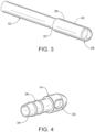
Figure 3 is a perspective view of yet another embodiment of an enteral tube illustrating a tip encasing a distal end portion of a tube; -
Figure 4 is another perspective view of the tip showing the proximal end thereof; -
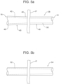
Figure 5a is a partial plan view of a tube having a gradually increasing lumen cross section in a portion positioned within a patient; -
Figure 5b is a partial plan view of a tube having a gradually increasing lumen cross section and a uniform outer cross section; -
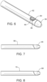
Figure 6 is a perspective view of an alternate enteral tube illustrating a distal end portion of a tube and a tip; -
Figure 7 is a side elevational view of another alternate tip showing an oblique connection between a tube and the tip; and -
Figure 8 is a side elevational view of still another alternate tip showing a curved connection between a tube and the tip. - Reference will now be made in detail to the present described embodiments of the invention, examples of which are illustrated in the accompanying drawing figures, wherein like numerals are used to represent like elements.
- Reference is now made to
Figure 1 which partially illustrates atube 12 for placement within a patient (P). In this embodiment, the tube is an enteral tube which includes, but is not limited to, nasogastric tubes, nasoduodenal tubes, oral gastric tubes, oral duodenal tube, and feeding tubes located distal to the duodenum. Other embodiments may utilize other types of tubes, for example, gastrostomy or G-tubes inserted through the patient's abdomen to deliver nutrition directly to the stomach. While some designs utilize a bolster system designed to prevent withdrawal of the gastrostomy tube, others utilize other anchor means (e.g., inflatable balloons) to prevent withdrawal. In all designs, a dissolvable tip (solid or otherwise) may be utilized to improve the insertion process by limiting patient discomfort while ultimately allowing for the free flow of nutrients through the tube. One family of such gastrostomy devices is marketed under the brand MiniONE® including balloon and non-balloon devices. As shown, atube assembly 10 includes the enteral tube, ortube 12, and atip 14. - The
tube 12 includes a lumen extending a length of the tube from a proximal end portion (not shown) to adistal end portion 18 having an orifice therein. The describedtip 14 defines avent 20 and adistal aperture 22 for a guidewire (not shown) to pass through if desired. A square or butt connection between thetube 12 andtip 14 is shown with a proximal portion of the tip being hidden from view and positioned within the tube in this figure. As described below, other methods of attaching thetip 14 to thetube 12 may be utilized. - Since the
tip 14 is only useful during tube insertion, the tip is made of a dissolvable material. In other words, thetip 14 is dissolvable. More specifically, thetip 14 is designed to remain intact to facilitate the insertion process and placement of thetube 12 and then dissolve away. This leaves an unobstructed distal opening in thetube 12 encompassing its full inner diameter and allowing fluid flow along the long axis of the tube (designatedreference numeral 15 inFigure 1 ) without any change in direction. In other words, thetip 14 comprises a material, or materials, which are soluble and suitable for human or animal consumption. One soluble material is a polymer marketed under the trademark Affinisol®. Broadly speaking, any soluble material may be utilized. In addition to being soluble, the material or materials may include additional properties such as lubriciousness when exposed to a moist environment. More specifically, the tip material may be coated with a water activated lubricious coating to facilitate gliding during insertion. - As best shown in
Figure 2 , thetip 14 includes a conical or bullet shaped distal contoured surface orface 24. In the described embodiment (best shown inFigure 1 ), an outer diameter of thetip 14 substantially corresponds to an outer diameter of thetube 12 to which it is attached creating a smooth outer surface even at the butt joint. Limiting the outer diameter of thetip 14 in these embodiments enhances patient comfort and eases the insertion process particularly when moving through narrower portions of the gastrointestinal tract. - While maintaining the outer diameter of the tip to substantially correspond with the outer diameter of the tube provides certain advantages, other embodiments may include an outer tip diameter that is larger than the outer diameter of the tube. As shown in
Figure 3 , for example, analternate tip 26 may include aproximal end portion 28 sized to receive adistal end portion 30 of atube 32 therein. In this embodiment, thetip 26 encases or is attached to an outside diameter of thedistal end portion 30 of the tube. In other words, the dissolving material may provide a covering over a distal end of the tube. Thetip 26 may be formed by dipping thetube 32 in the dissolving material for example, may be pre-formed or molded, or otherwise. - As shown in
Figure 4 , the diameter of the describedtip 14 is reduced to just less than an inner diameter of thetube 12 along aproximal portion 34 such that thetip 14 is held in place within the tube's distal end portion 18 (seeFigure 1 ) by friction. Alternate embodiments, ensure retention of thetip 14 by means of adhesives, the natural tackiness of the tip material, or other retention means known in the art. One ormore ridges 36, rings, or other mechanical features may be positioned on theproximal portion 34 of thetip 14 to provide retentive forces. Even more alternate embodiments may utilize a partially dissolvable tip. For example, theproximal portion 34 of the describedtip 14 may be dissolvable to ensure the tip is dislocated from thetube 12 leaving an unobstructed distal opening in thetube 12 allowing fluid flow along the long axis of the tube. The remaining portion of thetip 14 may not be dissolvable but would dislodge from thetube 12 and pass through the gastrointestinal tract of the patient (P). In the embodiment shown inFigure 3 , the portion of thetip 26 surrounding thedistal end portion 30 of thetube 32 may be dissolvable to ensure the tip is dislocated from the tube while the remaining portion of the tip may not be dissolvable. In other embodiments, varying portions of the tip may be dissolvable so long as the dissolvable portions are sufficient to ensure the tip is dislocated from the tube. - In alternate embodiments shown in
Figures 5a and 5b , atube 38 may have a tapered configuration. In other words, aportion 40 of thetube 38 which will reside within a patient (P) may have a gradually increasinglumen cross section 42 from aproximal end 44 to adistal end 46. Aportion 48 of thetube 38 which remains external to the patient (P) may have a uniformlumen cross section 50 or, in an alternate embodiment, a taperedlumen cross section 52 may extend along an entirety of atube 54, as shown inFigure 5b , or along a portion thereof. For example, the lumen cross section may gradually increase from a proximal end portion oftube 52 toward a distal end or a distal end portion of thetube 54. Even more, an outer cross section of the tube may be uniform, as shown inFigure 5b , or may gradually increase in areas where the lumen cross section gradually increases as shown inFigure 5a . If the tube is round, the lumen cross section will necessarily be an inner diameter of the tube. - The purpose of providing a gradually increasing lumen cross section is to provide a smaller cross section at the area which would be best for patient comfort, such as the portion of the
tube 38 residing in the nose. Then, distal to this, having the gradual increase in cross section makes clogging less likely. When thetube 38 is in place, the patient (P) will not be able to detect the larger cross section of the tube distally. - Further, should a clog develop in the tapered
portion 40 of thetube 38 within the patient (P), gentle pressure with a suitable fluid flush will make clearing the clog more likely than with a uniform lumen cross section. To further diminish the risk of clogging, an interior surface of thetube 38 may be coated in a non-stick or lubricious material. Clogs located in the constant lumencross section portion 48 of thetube 38 would be mostly external to the patient (P). In thisportion 48, external pressure may also be applied by the clinician to thetube 38 to milk or break up the clog and enhance clearing along with fluid flush. - In such alternate embodiments wherein the tube has a tapered inner diameter, the tip can be shaped to conform with the tapering inner diameter of the tube. For example, the proximal portion of the tip could be conically or frusto conically shaped.
- Returning to the embodiment shown in
Figure 1 and as suggested above, thetip 14 may define one or more apertures, holes, or vents 20. A central aperture orpassageway 22 located axially along its length allows placement of thetube 12 by passing it over a guidewire (not shown) such is commonly utilized during fluoroscopic placement or endoscopic placement of feeding tubes. Thecentral aperture 22 does not compromise placement with or without a stylet which remains completely within the lumen of thetube 12. Thecentral aperture 22 offers two additional advantages. First, thecentral aperture 22 increases the surface area available for contact with fluids passing through thetube 12 and gastrointestinal fluids thereby expediting dissolution of thetip 14. Second, in the case of tube placement under fluoroscopic guidance, small amounts of contrast material may be passed through thetube 12 andcentral aperture 22 of thetip 14 facilitating confirmation of tube position. In alternate embodiments, thetip 14 may be solid or may have a central aperture with no additional holes or vents. - While a
single vent 20 is shown throughout the figures, one or more vents may be integrated into a tip to allow a higher flow rate of water, radiographic contrast media, nutritional formula, or other fluids. Importantly, each vent creates a minimally restricted flow pathway for any fluids passing down the lumen of thetube 12. Hence, patients may receive nutritional formula as soon as thetube 12 has been placed into the gastrointestinal tract with no need to wait until thetip 14 has completely or partially dissolved. - While allowing a higher flow rate of fluids, the
vent 20 is formed such that the fluids exit thetube 12 via the vent at a substantially ninety-degree angle relative to the long axis of thetip 14 and tube. This configuration minimizes the risk that a guidewire inadvertently exists through thevent 20 rather than the centralguide wire aperture 22. Nonetheless, other embodiments may include vents within a tip that exit at angles greater than and/or less than 90 degrees. - In the embodiment shown in
Figure 1 , thevent 20 obviates the need for a vent defined by thetube 12 with the benefit of lower costs. In alternate embodiments, however, the one or more tip vents may be positioned more proximally such that the vents open through a corresponding one or more vents defined by the tube. As shown inFigure 6 , for example, avent 56 formed in atip 58 is located to cooperate with avent 60 defined by atube 62. In this arrangement, acuff 64 extends through thetube vent 56 to provide further resistance preventing thetip 58 from coming out of thetube 62. In all embodiments, the vent(s) may include a uniform inside diameter or a nonuniform diameter such as a taper. - Following placement of the tube, the tip will reside in the gastrointestinal tract, typically, in the stomach (whether an enteral or gastrostomy tube) or small bowel. Both anatomic areas provide an aqueous environment which will lead to dissolution of the tip thereby leaving the end, or orifice, of the tube open and completely unobstructed. In addition, fluids such as water or nutritional formulas moving through the tip vent(s) and/or central aperture/hole, if one or both are present, further expedite dissolution of the tip. In an alternate embodiment of a solid dissolvable tip without a central hole or vents, the user may force the tip out of the tube by means of air or water pressure generated with a syringe placed at the proximal end of the tube. The ejected tip would then dissolve in the gastrointestinal tract in due course while immediately allowing fluids to move through the distal end of the tube.
- As previously suggested, the
tip 14 may be attached to thetube 12 utilizing a square or butt connection as shown inFigure 1 . In addition, atip 64 andtube 66 may be shaped to form an oblique connection therebetween as shown inFigure 7 . Even more, atip 68 and atube 70 may be shaped to form a curved connection therebetween as shown inFigure 8 . - The foregoing has been presented for purposes of illustration and description. It is not intended to be exhaustive or to limit the embodiments to the precise form disclosed. Obvious modifications and variations are possible in light of the above teachings. For example, one or more vents may be formed along the
distal end portion 18 of thetube 12 shown inFigure 1 . Such tube vents may be in place of vents formed in the tip 14 (e.g., vent 20) or may be in addition thereto. In addition, a radiopaque material such as barium, for example, may be incorporated in the tip to assist in location of the tip during fluoroscopic placement. Even more, the proximal aspect of the tip may be solid or have a lumen. The proximal internal edge may have a chamfered or rounded shape to facilitate passing of a guidewire from proximal to distal. Likewise, the proximal outside edge may also be chamfered or rounded to facilitate placement inside of a tube. Further, the outside diameter of the proximal portion may be tapered to facilitate placement inside of a tube. The distal shape of the lumen may be configured conically to further direct a guidewire through the central guidewire hole.
Claims (15)
- An enteral tube assembly, comprising:a tube (12) for placement within a patient, the tube having a lumen (42) increasing in diameter along at least a portion (40) of the tube to a distal end (46); anda dissolvable tip (14) attached to the distal end wherein only a portion of the tip (14) is dissolvable to ensure that the tip is dislocated from the tube.
- The tube assembly of claim 1 which is a nasogastric tube assembly.
- The tube assembly of claim 1, wherein the dissolvable tip (14) is partially inserted into the tube.
- The tube assembly of claim 3, wherein the dissolvable tip (14) includes a proximal end portion (34) for insertion into the tube (12), wherein the proximal end portion includes at least one ridge (36).
- The tube assembly of claim 1, wherein the dissolvable tip (14) is partially inserted into the lumen (42).
- The tube assembly of claim 5, wherein the dissolvable tip (14) includes a proximal end portion (34) for insertion into the lumen (42).
- The tube assembly of claim 6, wherein the dissolvable tip (14) includes a central aperture (22).
- The tube assembly of claim 6, wherein the dissolvable tip (14) includes at least one vent (20).
- The tube assembly of claim 6, wherein an outer diameter of the tube (12) and an outer diameter of the tip (14) are substantially the same.
- The tube assembly of claim 6, wherein the dissolvable tip (14) includes a conical distal end.
- The tube assembly of claim 1, wherein the tube (22) includes at least one laterally facing vent (60).
- The tube assembly of claim 11, wherein the dissolvable tip (14) includes a collar (64) extending through the tube vent (56).
- The tube assembly of claim 1, wherein the dissolvable tip (58) includes at least one vent (56) and the tube (62) includes at least one corresponding vent (60).
- The tube assembly of claim 13, wherein the dissolvable tip (58) includes a collar (64) extending at least partially through the tube vent (60).
- The tube assembly of claim 1, further comprising a balloon.
Priority Applications (1)
| Application Number | Priority Date | Filing Date | Title |
|---|---|---|---|
| EP22192608.2A EP4115937A1 (en) | 2018-02-13 | 2019-02-11 | Tube assembly and dissolvable tip |
Applications Claiming Priority (2)
| Application Number | Priority Date | Filing Date | Title |
|---|---|---|---|
| US201862629989P | 2018-02-13 | 2018-02-13 | |
| PCT/US2019/017418 WO2019160785A1 (en) | 2018-02-13 | 2019-02-11 | Tube assembly and dissolvable tip |
Related Child Applications (2)
| Application Number | Title | Priority Date | Filing Date |
|---|---|---|---|
| EP22192608.2A Division-Into EP4115937A1 (en) | 2018-02-13 | 2019-02-11 | Tube assembly and dissolvable tip |
| EP22192608.2A Division EP4115937A1 (en) | 2018-02-13 | 2019-02-11 | Tube assembly and dissolvable tip |
Publications (3)
| Publication Number | Publication Date |
|---|---|
| EP3752233A1 EP3752233A1 (en) | 2020-12-23 |
| EP3752233A4 EP3752233A4 (en) | 2021-11-10 |
| EP3752233B1 true EP3752233B1 (en) | 2023-08-16 |
Family
ID=67619563
Family Applications (2)
| Application Number | Title | Priority Date | Filing Date |
|---|---|---|---|
| EP19754912.4A Active EP3752233B1 (en) | 2018-02-13 | 2019-02-11 | Tube assembly and dissolvable tip |
| EP22192608.2A Withdrawn EP4115937A1 (en) | 2018-02-13 | 2019-02-11 | Tube assembly and dissolvable tip |
Family Applications After (1)
| Application Number | Title | Priority Date | Filing Date |
|---|---|---|---|
| EP22192608.2A Withdrawn EP4115937A1 (en) | 2018-02-13 | 2019-02-11 | Tube assembly and dissolvable tip |
Country Status (5)
| Country | Link |
|---|---|
| US (1) | US20210045973A1 (en) |
| EP (2) | EP3752233B1 (en) |
| JP (1) | JP7333961B2 (en) |
| BR (1) | BR112020015968A2 (en) |
| WO (1) | WO2019160785A1 (en) |
Families Citing this family (2)
| Publication number | Priority date | Publication date | Assignee | Title |
|---|---|---|---|---|
| JP2023527656A (en) * | 2020-05-04 | 2023-06-30 | ワード,エルエルシー | enteral feeding tube |
| WO2022098898A1 (en) * | 2020-11-04 | 2022-05-12 | Werd, Llc | Tube assemblies |
Family Cites Families (9)
| Publication number | Priority date | Publication date | Assignee | Title |
|---|---|---|---|---|
| US2603217A (en) * | 1952-07-15 | mcshirley | ||
| US5049138A (en) * | 1989-11-13 | 1991-09-17 | Boston Scientific Corporation | Catheter with dissolvable tip |
| US5281212A (en) * | 1992-02-18 | 1994-01-25 | Angeion Corporation | Laser catheter with monitor and dissolvable tip |
| US6332877B1 (en) * | 1998-05-12 | 2001-12-25 | Novartis Ag | Ostomy tube placement tip |
| US6673058B2 (en) * | 2001-06-20 | 2004-01-06 | Scimed Life Systems, Inc. | Temporary dilating tip for gastro-intestinal tubes |
| CA2756573A1 (en) * | 2008-08-19 | 2010-02-25 | Micro Therapeutics, Inc. | Detachable tip microcatheter |
| JP2013116220A (en) * | 2011-12-02 | 2013-06-13 | Tsukada Medical Res:Kk | Cylindrical member and balloon catheter mounted with the same |
| BR112017026854A2 (en) * | 2015-07-06 | 2018-08-14 | Werd Llc | temporary tubes and system for placing them in a patient |
| GB2552924B (en) * | 2016-05-13 | 2021-10-06 | Gbuk Group Ltd | Feeding tube |
-
2019
- 2019-02-11 EP EP19754912.4A patent/EP3752233B1/en active Active
- 2019-02-11 EP EP22192608.2A patent/EP4115937A1/en not_active Withdrawn
- 2019-02-11 BR BR112020015968-9A patent/BR112020015968A2/en active Search and Examination
- 2019-02-11 WO PCT/US2019/017418 patent/WO2019160785A1/en not_active Ceased
- 2019-02-11 JP JP2020541477A patent/JP7333961B2/en active Active
- 2019-02-11 US US16/964,419 patent/US20210045973A1/en not_active Abandoned
Also Published As
| Publication number | Publication date |
|---|---|
| US20210045973A1 (en) | 2021-02-18 |
| WO2019160785A1 (en) | 2019-08-22 |
| JP2021512674A (en) | 2021-05-20 |
| EP4115937A1 (en) | 2023-01-11 |
| JP7333961B2 (en) | 2023-08-28 |
| EP3752233A4 (en) | 2021-11-10 |
| EP3752233A1 (en) | 2020-12-23 |
| BR112020015968A2 (en) | 2020-12-15 |
Similar Documents
| Publication | Publication Date | Title |
|---|---|---|
| US4698056A (en) | Enteric feeding device | |
| US5902285A (en) | Jejunal feeding tube | |
| US6039714A (en) | Collapsible retention bolster for gastrostomy and other ostomy tubes | |
| US6673058B2 (en) | Temporary dilating tip for gastro-intestinal tubes | |
| JP5184512B2 (en) | Supply device, bolster apparatus, and method for producing the same | |
| US7048722B2 (en) | Catheter | |
| US6332877B1 (en) | Ostomy tube placement tip | |
| US7628775B2 (en) | Safety Y-port adaptor and medical catheter assembly including the same | |
| JP4532285B2 (en) | Medical catheter assembly including a connector for use with a medical catheter, and method for assembling the medical catheter assembly | |
| JPH0318378A (en) | Tube for setting stomachic wax | |
| EP1567220B1 (en) | Catheter | |
| EP3752233B1 (en) | Tube assembly and dissolvable tip | |
| JP5907746B2 (en) | Low profile GJ feeding device | |
| EP0853937A1 (en) | Gastrostomy tube device for enteral nutrition | |
| EP4146137B1 (en) | Enteral feeding tube | |
| GB2552924A (en) | Feeding tube | |
| JP2007530143A (en) | Delivery device and method of delivering liquid and nutrients to patient | |
| JP6718664B2 (en) | Medical tube and medical tube set | |
| WO2018083451A1 (en) | Improvements to a bolus, an enteral tube and/or a catheter | |
| JPH0748269Y2 (en) | Gastrointestinal catheter | |
| JPH0539704Y2 (en) | ||
| BR112022018554B1 (en) | ENTERAL FEEDING TUBE | |
| GB2576158A (en) | Enteral feeding tube |
Legal Events
| Date | Code | Title | Description |
|---|---|---|---|
| STAA | Information on the status of an ep patent application or granted ep patent |
Free format text: STATUS: THE INTERNATIONAL PUBLICATION HAS BEEN MADE |
|
| PUAI | Public reference made under article 153(3) epc to a published international application that has entered the european phase |
Free format text: ORIGINAL CODE: 0009012 |
|
| STAA | Information on the status of an ep patent application or granted ep patent |
Free format text: STATUS: REQUEST FOR EXAMINATION WAS MADE |
|
| 17P | Request for examination filed |
Effective date: 20200817 |
|
| AK | Designated contracting states |
Kind code of ref document: A1 Designated state(s): AL AT BE BG CH CY CZ DE DK EE ES FI FR GB GR HR HU IE IS IT LI LT LU LV MC MK MT NL NO PL PT RO RS SE SI SK SM TR |
|
| AX | Request for extension of the european patent |
Extension state: BA ME |
|
| DAV | Request for validation of the european patent (deleted) | ||
| DAX | Request for extension of the european patent (deleted) | ||
| A4 | Supplementary search report drawn up and despatched |
Effective date: 20211013 |
|
| RIC1 | Information provided on ipc code assigned before grant |
Ipc: A61J 15/00 20060101ALI20211007BHEP Ipc: A61M 25/00 20060101AFI20211007BHEP |
|
| GRAP | Despatch of communication of intention to grant a patent |
Free format text: ORIGINAL CODE: EPIDOSNIGR1 |
|
| STAA | Information on the status of an ep patent application or granted ep patent |
Free format text: STATUS: GRANT OF PATENT IS INTENDED |
|
| INTG | Intention to grant announced |
Effective date: 20230426 |
|
| GRAS | Grant fee paid |
Free format text: ORIGINAL CODE: EPIDOSNIGR3 |
|
| GRAA | (expected) grant |
Free format text: ORIGINAL CODE: 0009210 |
|
| STAA | Information on the status of an ep patent application or granted ep patent |
Free format text: STATUS: THE PATENT HAS BEEN GRANTED |
|
| AK | Designated contracting states |
Kind code of ref document: B1 Designated state(s): AL AT BE BG CH CY CZ DE DK EE ES FI FR GB GR HR HU IE IS IT LI LT LU LV MC MK MT NL NO PL PT RO RS SE SI SK SM TR |
|
| REG | Reference to a national code |
Ref country code: CH Ref legal event code: EP |
|
| REG | Reference to a national code |
Ref country code: DE Ref legal event code: R096 Ref document number: 602019035162 Country of ref document: DE |
|
| REG | Reference to a national code |
Ref country code: IE Ref legal event code: FG4D |
|
| REG | Reference to a national code |
Ref country code: LT Ref legal event code: MG9D |
|
| REG | Reference to a national code |
Ref country code: NL Ref legal event code: MP Effective date: 20230816 |
|
| REG | Reference to a national code |
Ref country code: AT Ref legal event code: MK05 Ref document number: 1599423 Country of ref document: AT Kind code of ref document: T Effective date: 20230816 |
|
| PG25 | Lapsed in a contracting state [announced via postgrant information from national office to epo] |
Ref country code: GR Free format text: LAPSE BECAUSE OF FAILURE TO SUBMIT A TRANSLATION OF THE DESCRIPTION OR TO PAY THE FEE WITHIN THE PRESCRIBED TIME-LIMIT Effective date: 20231117 |
|
| PG25 | Lapsed in a contracting state [announced via postgrant information from national office to epo] |
Ref country code: IS Free format text: LAPSE BECAUSE OF FAILURE TO SUBMIT A TRANSLATION OF THE DESCRIPTION OR TO PAY THE FEE WITHIN THE PRESCRIBED TIME-LIMIT Effective date: 20231216 |
|
| PG25 | Lapsed in a contracting state [announced via postgrant information from national office to epo] |
Ref country code: SE Free format text: LAPSE BECAUSE OF FAILURE TO SUBMIT A TRANSLATION OF THE DESCRIPTION OR TO PAY THE FEE WITHIN THE PRESCRIBED TIME-LIMIT Effective date: 20230816 Ref country code: RS Free format text: LAPSE BECAUSE OF FAILURE TO SUBMIT A TRANSLATION OF THE DESCRIPTION OR TO PAY THE FEE WITHIN THE PRESCRIBED TIME-LIMIT Effective date: 20230816 Ref country code: PT Free format text: LAPSE BECAUSE OF FAILURE TO SUBMIT A TRANSLATION OF THE DESCRIPTION OR TO PAY THE FEE WITHIN THE PRESCRIBED TIME-LIMIT Effective date: 20231218 Ref country code: NO Free format text: LAPSE BECAUSE OF FAILURE TO SUBMIT A TRANSLATION OF THE DESCRIPTION OR TO PAY THE FEE WITHIN THE PRESCRIBED TIME-LIMIT Effective date: 20231116 Ref country code: NL Free format text: LAPSE BECAUSE OF FAILURE TO SUBMIT A TRANSLATION OF THE DESCRIPTION OR TO PAY THE FEE WITHIN THE PRESCRIBED TIME-LIMIT Effective date: 20230816 Ref country code: LV Free format text: LAPSE BECAUSE OF FAILURE TO SUBMIT A TRANSLATION OF THE DESCRIPTION OR TO PAY THE FEE WITHIN THE PRESCRIBED TIME-LIMIT Effective date: 20230816 Ref country code: LT Free format text: LAPSE BECAUSE OF FAILURE TO SUBMIT A TRANSLATION OF THE DESCRIPTION OR TO PAY THE FEE WITHIN THE PRESCRIBED TIME-LIMIT Effective date: 20230816 Ref country code: IS Free format text: LAPSE BECAUSE OF FAILURE TO SUBMIT A TRANSLATION OF THE DESCRIPTION OR TO PAY THE FEE WITHIN THE PRESCRIBED TIME-LIMIT Effective date: 20231216 Ref country code: HR Free format text: LAPSE BECAUSE OF FAILURE TO SUBMIT A TRANSLATION OF THE DESCRIPTION OR TO PAY THE FEE WITHIN THE PRESCRIBED TIME-LIMIT Effective date: 20230816 Ref country code: GR Free format text: LAPSE BECAUSE OF FAILURE TO SUBMIT A TRANSLATION OF THE DESCRIPTION OR TO PAY THE FEE WITHIN THE PRESCRIBED TIME-LIMIT Effective date: 20231117 Ref country code: FI Free format text: LAPSE BECAUSE OF FAILURE TO SUBMIT A TRANSLATION OF THE DESCRIPTION OR TO PAY THE FEE WITHIN THE PRESCRIBED TIME-LIMIT Effective date: 20230816 Ref country code: AT Free format text: LAPSE BECAUSE OF FAILURE TO SUBMIT A TRANSLATION OF THE DESCRIPTION OR TO PAY THE FEE WITHIN THE PRESCRIBED TIME-LIMIT Effective date: 20230816 |
|
| PG25 | Lapsed in a contracting state [announced via postgrant information from national office to epo] |
Ref country code: PL Free format text: LAPSE BECAUSE OF FAILURE TO SUBMIT A TRANSLATION OF THE DESCRIPTION OR TO PAY THE FEE WITHIN THE PRESCRIBED TIME-LIMIT Effective date: 20230816 |
|
| PG25 | Lapsed in a contracting state [announced via postgrant information from national office to epo] |
Ref country code: ES Free format text: LAPSE BECAUSE OF FAILURE TO SUBMIT A TRANSLATION OF THE DESCRIPTION OR TO PAY THE FEE WITHIN THE PRESCRIBED TIME-LIMIT Effective date: 20230816 |
|
| PG25 | Lapsed in a contracting state [announced via postgrant information from national office to epo] |
Ref country code: SM Free format text: LAPSE BECAUSE OF FAILURE TO SUBMIT A TRANSLATION OF THE DESCRIPTION OR TO PAY THE FEE WITHIN THE PRESCRIBED TIME-LIMIT Effective date: 20230816 Ref country code: RO Free format text: LAPSE BECAUSE OF FAILURE TO SUBMIT A TRANSLATION OF THE DESCRIPTION OR TO PAY THE FEE WITHIN THE PRESCRIBED TIME-LIMIT Effective date: 20230816 Ref country code: ES Free format text: LAPSE BECAUSE OF FAILURE TO SUBMIT A TRANSLATION OF THE DESCRIPTION OR TO PAY THE FEE WITHIN THE PRESCRIBED TIME-LIMIT Effective date: 20230816 Ref country code: EE Free format text: LAPSE BECAUSE OF FAILURE TO SUBMIT A TRANSLATION OF THE DESCRIPTION OR TO PAY THE FEE WITHIN THE PRESCRIBED TIME-LIMIT Effective date: 20230816 Ref country code: DK Free format text: LAPSE BECAUSE OF FAILURE TO SUBMIT A TRANSLATION OF THE DESCRIPTION OR TO PAY THE FEE WITHIN THE PRESCRIBED TIME-LIMIT Effective date: 20230816 Ref country code: CZ Free format text: LAPSE BECAUSE OF FAILURE TO SUBMIT A TRANSLATION OF THE DESCRIPTION OR TO PAY THE FEE WITHIN THE PRESCRIBED TIME-LIMIT Effective date: 20230816 Ref country code: SK Free format text: LAPSE BECAUSE OF FAILURE TO SUBMIT A TRANSLATION OF THE DESCRIPTION OR TO PAY THE FEE WITHIN THE PRESCRIBED TIME-LIMIT Effective date: 20230816 |
|
| REG | Reference to a national code |
Ref country code: DE Ref legal event code: R097 Ref document number: 602019035162 Country of ref document: DE |
|
| PLBE | No opposition filed within time limit |
Free format text: ORIGINAL CODE: 0009261 |
|
| STAA | Information on the status of an ep patent application or granted ep patent |
Free format text: STATUS: NO OPPOSITION FILED WITHIN TIME LIMIT |
|
| 26N | No opposition filed |
Effective date: 20240517 |
|
| PG25 | Lapsed in a contracting state [announced via postgrant information from national office to epo] |
Ref country code: IT Free format text: LAPSE BECAUSE OF FAILURE TO SUBMIT A TRANSLATION OF THE DESCRIPTION OR TO PAY THE FEE WITHIN THE PRESCRIBED TIME-LIMIT Effective date: 20230816 Ref country code: SI Free format text: LAPSE BECAUSE OF FAILURE TO SUBMIT A TRANSLATION OF THE DESCRIPTION OR TO PAY THE FEE WITHIN THE PRESCRIBED TIME-LIMIT Effective date: 20230816 |
|
| REG | Reference to a national code |
Ref country code: DE Ref legal event code: R119 Ref document number: 602019035162 Country of ref document: DE |
|
| PG25 | Lapsed in a contracting state [announced via postgrant information from national office to epo] |
Ref country code: MC Free format text: LAPSE BECAUSE OF FAILURE TO SUBMIT A TRANSLATION OF THE DESCRIPTION OR TO PAY THE FEE WITHIN THE PRESCRIBED TIME-LIMIT Effective date: 20230816 |
|
| REG | Reference to a national code |
Ref country code: CH Ref legal event code: PL |
|
| PG25 | Lapsed in a contracting state [announced via postgrant information from national office to epo] |
Ref country code: LU Free format text: LAPSE BECAUSE OF NON-PAYMENT OF DUE FEES Effective date: 20240211 |
|
| PG25 | Lapsed in a contracting state [announced via postgrant information from national office to epo] |
Ref country code: CH Free format text: LAPSE BECAUSE OF NON-PAYMENT OF DUE FEES Effective date: 20240229 |
|
| GBPC | Gb: european patent ceased through non-payment of renewal fee |
Effective date: 20240211 |
|
| PG25 | Lapsed in a contracting state [announced via postgrant information from national office to epo] |
Ref country code: LU Free format text: LAPSE BECAUSE OF NON-PAYMENT OF DUE FEES Effective date: 20240211 Ref country code: CH Free format text: LAPSE BECAUSE OF NON-PAYMENT OF DUE FEES Effective date: 20240229 |
|
| PG25 | Lapsed in a contracting state [announced via postgrant information from national office to epo] |
Ref country code: BG Free format text: LAPSE BECAUSE OF FAILURE TO SUBMIT A TRANSLATION OF THE DESCRIPTION OR TO PAY THE FEE WITHIN THE PRESCRIBED TIME-LIMIT Effective date: 20230816 |
|
| PG25 | Lapsed in a contracting state [announced via postgrant information from national office to epo] |
Ref country code: BG Free format text: LAPSE BECAUSE OF FAILURE TO SUBMIT A TRANSLATION OF THE DESCRIPTION OR TO PAY THE FEE WITHIN THE PRESCRIBED TIME-LIMIT Effective date: 20230816 |
|
| REG | Reference to a national code |
Ref country code: BE Ref legal event code: MM Effective date: 20240229 |
|
| PG25 | Lapsed in a contracting state [announced via postgrant information from national office to epo] |
Ref country code: DE Free format text: LAPSE BECAUSE OF NON-PAYMENT OF DUE FEES Effective date: 20240903 |
|
| PG25 | Lapsed in a contracting state [announced via postgrant information from national office to epo] |
Ref country code: BE Free format text: LAPSE BECAUSE OF NON-PAYMENT OF DUE FEES Effective date: 20240229 |
|
| PG25 | Lapsed in a contracting state [announced via postgrant information from national office to epo] |
Ref country code: GB Free format text: LAPSE BECAUSE OF NON-PAYMENT OF DUE FEES Effective date: 20240211 |
|
| PG25 | Lapsed in a contracting state [announced via postgrant information from national office to epo] |
Ref country code: FR Free format text: LAPSE BECAUSE OF NON-PAYMENT OF DUE FEES Effective date: 20240229 |
|
| PG25 | Lapsed in a contracting state [announced via postgrant information from national office to epo] |
Ref country code: IE Free format text: LAPSE BECAUSE OF NON-PAYMENT OF DUE FEES Effective date: 20240211 |
|
| PG25 | Lapsed in a contracting state [announced via postgrant information from national office to epo] |
Ref country code: IE Free format text: LAPSE BECAUSE OF NON-PAYMENT OF DUE FEES Effective date: 20240211 Ref country code: GB Free format text: LAPSE BECAUSE OF NON-PAYMENT OF DUE FEES Effective date: 20240211 Ref country code: FR Free format text: LAPSE BECAUSE OF NON-PAYMENT OF DUE FEES Effective date: 20240229 Ref country code: DE Free format text: LAPSE BECAUSE OF NON-PAYMENT OF DUE FEES Effective date: 20240903 Ref country code: BE Free format text: LAPSE BECAUSE OF NON-PAYMENT OF DUE FEES Effective date: 20240229 |
|
| PG25 | Lapsed in a contracting state [announced via postgrant information from national office to epo] |
Ref country code: CY Free format text: LAPSE BECAUSE OF FAILURE TO SUBMIT A TRANSLATION OF THE DESCRIPTION OR TO PAY THE FEE WITHIN THE PRESCRIBED TIME-LIMIT; INVALID AB INITIO Effective date: 20190211 |
|
| PG25 | Lapsed in a contracting state [announced via postgrant information from national office to epo] |
Ref country code: HU Free format text: LAPSE BECAUSE OF FAILURE TO SUBMIT A TRANSLATION OF THE DESCRIPTION OR TO PAY THE FEE WITHIN THE PRESCRIBED TIME-LIMIT; INVALID AB INITIO Effective date: 20190211 |