EP3752102B1 - Wirbelsäulenimplantatsystem - Google Patents
Wirbelsäulenimplantatsystem Download PDFInfo
- Publication number
- EP3752102B1 EP3752102B1 EP19754596.5A EP19754596A EP3752102B1 EP 3752102 B1 EP3752102 B1 EP 3752102B1 EP 19754596 A EP19754596 A EP 19754596A EP 3752102 B1 EP3752102 B1 EP 3752102B1
- Authority
- EP
- European Patent Office
- Prior art keywords
- end cap
- spinal implant
- flange
- flange portion
- recess
- Prior art date
- Legal status (The legal status is an assumption and is not a legal conclusion. Google has not performed a legal analysis and makes no representation as to the accuracy of the status listed.)
- Active
Links
Images





Classifications
-
- A—HUMAN NECESSITIES
- A61—MEDICAL OR VETERINARY SCIENCE; HYGIENE
- A61F—FILTERS IMPLANTABLE INTO BLOOD VESSELS; PROSTHESES; DEVICES PROVIDING PATENCY TO, OR PREVENTING COLLAPSING OF, TUBULAR STRUCTURES OF THE BODY, e.g. STENTS; ORTHOPAEDIC, NURSING OR CONTRACEPTIVE DEVICES; FOMENTATION; TREATMENT OR PROTECTION OF EYES OR EARS; BANDAGES, DRESSINGS OR ABSORBENT PADS; FIRST-AID KITS
- A61F2/00—Filters implantable into blood vessels; Prostheses, i.e. artificial substitutes or replacements for parts of the body; Appliances for connecting them with the body; Devices providing patency to, or preventing collapsing of, tubular structures of the body, e.g. stents
- A61F2/02—Prostheses implantable into the body
- A61F2/30—Joints
- A61F2/44—Joints for the spine, e.g. vertebrae, spinal discs
- A61F2/4455—Joints for the spine, e.g. vertebrae, spinal discs for the fusion of spinal bodies, e.g. intervertebral fusion of adjacent spinal bodies, e.g. fusion cages
- A61F2/4465—Joints for the spine, e.g. vertebrae, spinal discs for the fusion of spinal bodies, e.g. intervertebral fusion of adjacent spinal bodies, e.g. fusion cages having a circular or kidney shaped cross-section substantially perpendicular to the axis of the spine
-
- A—HUMAN NECESSITIES
- A61—MEDICAL OR VETERINARY SCIENCE; HYGIENE
- A61F—FILTERS IMPLANTABLE INTO BLOOD VESSELS; PROSTHESES; DEVICES PROVIDING PATENCY TO, OR PREVENTING COLLAPSING OF, TUBULAR STRUCTURES OF THE BODY, e.g. STENTS; ORTHOPAEDIC, NURSING OR CONTRACEPTIVE DEVICES; FOMENTATION; TREATMENT OR PROTECTION OF EYES OR EARS; BANDAGES, DRESSINGS OR ABSORBENT PADS; FIRST-AID KITS
- A61F2/00—Filters implantable into blood vessels; Prostheses, i.e. artificial substitutes or replacements for parts of the body; Appliances for connecting them with the body; Devices providing patency to, or preventing collapsing of, tubular structures of the body, e.g. stents
- A61F2/02—Prostheses implantable into the body
- A61F2/30—Joints
- A61F2/44—Joints for the spine, e.g. vertebrae, spinal discs
-
- A—HUMAN NECESSITIES
- A61—MEDICAL OR VETERINARY SCIENCE; HYGIENE
- A61F—FILTERS IMPLANTABLE INTO BLOOD VESSELS; PROSTHESES; DEVICES PROVIDING PATENCY TO, OR PREVENTING COLLAPSING OF, TUBULAR STRUCTURES OF THE BODY, e.g. STENTS; ORTHOPAEDIC, NURSING OR CONTRACEPTIVE DEVICES; FOMENTATION; TREATMENT OR PROTECTION OF EYES OR EARS; BANDAGES, DRESSINGS OR ABSORBENT PADS; FIRST-AID KITS
- A61F2/00—Filters implantable into blood vessels; Prostheses, i.e. artificial substitutes or replacements for parts of the body; Appliances for connecting them with the body; Devices providing patency to, or preventing collapsing of, tubular structures of the body, e.g. stents
- A61F2/02—Prostheses implantable into the body
- A61F2/30—Joints
- A61F2/44—Joints for the spine, e.g. vertebrae, spinal discs
- A61F2/442—Intervertebral or spinal discs, e.g. resilient
- A61F2/4425—Intervertebral or spinal discs, e.g. resilient made of articulated components
-
- A—HUMAN NECESSITIES
- A61—MEDICAL OR VETERINARY SCIENCE; HYGIENE
- A61F—FILTERS IMPLANTABLE INTO BLOOD VESSELS; PROSTHESES; DEVICES PROVIDING PATENCY TO, OR PREVENTING COLLAPSING OF, TUBULAR STRUCTURES OF THE BODY, e.g. STENTS; ORTHOPAEDIC, NURSING OR CONTRACEPTIVE DEVICES; FOMENTATION; TREATMENT OR PROTECTION OF EYES OR EARS; BANDAGES, DRESSINGS OR ABSORBENT PADS; FIRST-AID KITS
- A61F2/00—Filters implantable into blood vessels; Prostheses, i.e. artificial substitutes or replacements for parts of the body; Appliances for connecting them with the body; Devices providing patency to, or preventing collapsing of, tubular structures of the body, e.g. stents
- A61F2/02—Prostheses implantable into the body
- A61F2/30—Joints
- A61F2/44—Joints for the spine, e.g. vertebrae, spinal discs
- A61F2/4455—Joints for the spine, e.g. vertebrae, spinal discs for the fusion of spinal bodies, e.g. intervertebral fusion of adjacent spinal bodies, e.g. fusion cages
- A61F2/446—Joints for the spine, e.g. vertebrae, spinal discs for the fusion of spinal bodies, e.g. intervertebral fusion of adjacent spinal bodies, e.g. fusion cages having a circular or elliptical cross-section substantially parallel to the axis of the spine, e.g. cylinders or frustocones
-
- A—HUMAN NECESSITIES
- A61—MEDICAL OR VETERINARY SCIENCE; HYGIENE
- A61B—DIAGNOSIS; SURGERY; IDENTIFICATION
- A61B17/00—Surgical instruments, devices or methods
- A61B17/56—Surgical instruments or methods for treatment of bones or joints; Devices specially adapted therefor
- A61B17/58—Surgical instruments or methods for treatment of bones or joints; Devices specially adapted therefor for osteosynthesis, e.g. bone plates, screws or setting implements
- A61B17/68—Internal fixation devices, including fasteners and spinal fixators, even if a part thereof projects from the skin
- A61B17/70—Spinal positioners or stabilisers, e.g. stabilisers comprising fluid filler in an implant
- A61B17/7059—Cortical plates
-
- A—HUMAN NECESSITIES
- A61—MEDICAL OR VETERINARY SCIENCE; HYGIENE
- A61B—DIAGNOSIS; SURGERY; IDENTIFICATION
- A61B17/00—Surgical instruments, devices or methods
- A61B17/02—Surgical instruments, devices or methods for holding wounds open, e.g. retractors; Tractors
- A61B17/025—Joint distractors
- A61B2017/0256—Joint distractors for the spine
-
- A—HUMAN NECESSITIES
- A61—MEDICAL OR VETERINARY SCIENCE; HYGIENE
- A61F—FILTERS IMPLANTABLE INTO BLOOD VESSELS; PROSTHESES; DEVICES PROVIDING PATENCY TO, OR PREVENTING COLLAPSING OF, TUBULAR STRUCTURES OF THE BODY, e.g. STENTS; ORTHOPAEDIC, NURSING OR CONTRACEPTIVE DEVICES; FOMENTATION; TREATMENT OR PROTECTION OF EYES OR EARS; BANDAGES, DRESSINGS OR ABSORBENT PADS; FIRST-AID KITS
- A61F2/00—Filters implantable into blood vessels; Prostheses, i.e. artificial substitutes or replacements for parts of the body; Appliances for connecting them with the body; Devices providing patency to, or preventing collapsing of, tubular structures of the body, e.g. stents
- A61F2/02—Prostheses implantable into the body
- A61F2/30—Joints
- A61F2/44—Joints for the spine, e.g. vertebrae, spinal discs
- A61F2/442—Intervertebral or spinal discs, e.g. resilient
-
- A—HUMAN NECESSITIES
- A61—MEDICAL OR VETERINARY SCIENCE; HYGIENE
- A61F—FILTERS IMPLANTABLE INTO BLOOD VESSELS; PROSTHESES; DEVICES PROVIDING PATENCY TO, OR PREVENTING COLLAPSING OF, TUBULAR STRUCTURES OF THE BODY, e.g. STENTS; ORTHOPAEDIC, NURSING OR CONTRACEPTIVE DEVICES; FOMENTATION; TREATMENT OR PROTECTION OF EYES OR EARS; BANDAGES, DRESSINGS OR ABSORBENT PADS; FIRST-AID KITS
- A61F2/00—Filters implantable into blood vessels; Prostheses, i.e. artificial substitutes or replacements for parts of the body; Appliances for connecting them with the body; Devices providing patency to, or preventing collapsing of, tubular structures of the body, e.g. stents
- A61F2/02—Prostheses implantable into the body
- A61F2/30—Joints
- A61F2/44—Joints for the spine, e.g. vertebrae, spinal discs
- A61F2/4455—Joints for the spine, e.g. vertebrae, spinal discs for the fusion of spinal bodies, e.g. intervertebral fusion of adjacent spinal bodies, e.g. fusion cages
-
- A—HUMAN NECESSITIES
- A61—MEDICAL OR VETERINARY SCIENCE; HYGIENE
- A61F—FILTERS IMPLANTABLE INTO BLOOD VESSELS; PROSTHESES; DEVICES PROVIDING PATENCY TO, OR PREVENTING COLLAPSING OF, TUBULAR STRUCTURES OF THE BODY, e.g. STENTS; ORTHOPAEDIC, NURSING OR CONTRACEPTIVE DEVICES; FOMENTATION; TREATMENT OR PROTECTION OF EYES OR EARS; BANDAGES, DRESSINGS OR ABSORBENT PADS; FIRST-AID KITS
- A61F2/00—Filters implantable into blood vessels; Prostheses, i.e. artificial substitutes or replacements for parts of the body; Appliances for connecting them with the body; Devices providing patency to, or preventing collapsing of, tubular structures of the body, e.g. stents
- A61F2/02—Prostheses implantable into the body
- A61F2/30—Joints
- A61F2002/30001—Additional features of subject-matter classified in A61F2/28, A61F2/30 and subgroups thereof
- A61F2002/30108—Shapes
- A61F2002/30199—Three-dimensional shapes
- A61F2002/30224—Three-dimensional shapes cylindrical
-
- A—HUMAN NECESSITIES
- A61—MEDICAL OR VETERINARY SCIENCE; HYGIENE
- A61F—FILTERS IMPLANTABLE INTO BLOOD VESSELS; PROSTHESES; DEVICES PROVIDING PATENCY TO, OR PREVENTING COLLAPSING OF, TUBULAR STRUCTURES OF THE BODY, e.g. STENTS; ORTHOPAEDIC, NURSING OR CONTRACEPTIVE DEVICES; FOMENTATION; TREATMENT OR PROTECTION OF EYES OR EARS; BANDAGES, DRESSINGS OR ABSORBENT PADS; FIRST-AID KITS
- A61F2/00—Filters implantable into blood vessels; Prostheses, i.e. artificial substitutes or replacements for parts of the body; Appliances for connecting them with the body; Devices providing patency to, or preventing collapsing of, tubular structures of the body, e.g. stents
- A61F2/02—Prostheses implantable into the body
- A61F2/30—Joints
- A61F2002/30001—Additional features of subject-matter classified in A61F2/28, A61F2/30 and subgroups thereof
- A61F2002/30316—The prosthesis having different structural features at different locations within the same prosthesis; Connections between prosthetic parts; Special structural features of bone or joint prostheses not otherwise provided for
- A61F2002/30329—Connections or couplings between prosthetic parts, e.g. between modular parts; Connecting elements
- A61F2002/30331—Connections or couplings between prosthetic parts, e.g. between modular parts; Connecting elements made by longitudinally pushing a protrusion into a complementarily-shaped recess, e.g. held by friction fit
- A61F2002/30332—Conically- or frustoconically-shaped protrusion and recess
-
- A—HUMAN NECESSITIES
- A61—MEDICAL OR VETERINARY SCIENCE; HYGIENE
- A61F—FILTERS IMPLANTABLE INTO BLOOD VESSELS; PROSTHESES; DEVICES PROVIDING PATENCY TO, OR PREVENTING COLLAPSING OF, TUBULAR STRUCTURES OF THE BODY, e.g. STENTS; ORTHOPAEDIC, NURSING OR CONTRACEPTIVE DEVICES; FOMENTATION; TREATMENT OR PROTECTION OF EYES OR EARS; BANDAGES, DRESSINGS OR ABSORBENT PADS; FIRST-AID KITS
- A61F2/00—Filters implantable into blood vessels; Prostheses, i.e. artificial substitutes or replacements for parts of the body; Appliances for connecting them with the body; Devices providing patency to, or preventing collapsing of, tubular structures of the body, e.g. stents
- A61F2/02—Prostheses implantable into the body
- A61F2/30—Joints
- A61F2002/30001—Additional features of subject-matter classified in A61F2/28, A61F2/30 and subgroups thereof
- A61F2002/30316—The prosthesis having different structural features at different locations within the same prosthesis; Connections between prosthetic parts; Special structural features of bone or joint prostheses not otherwise provided for
- A61F2002/30329—Connections or couplings between prosthetic parts, e.g. between modular parts; Connecting elements
- A61F2002/30331—Connections or couplings between prosthetic parts, e.g. between modular parts; Connecting elements made by longitudinally pushing a protrusion into a complementarily-shaped recess, e.g. held by friction fit
- A61F2002/30362—Connections or couplings between prosthetic parts, e.g. between modular parts; Connecting elements made by longitudinally pushing a protrusion into a complementarily-shaped recess, e.g. held by friction fit with possibility of relative movement between the protrusion and the recess
- A61F2002/30364—Rotation about the common longitudinal axis
- A61F2002/30367—Rotation about the common longitudinal axis with additional means for preventing said rotation
-
- A—HUMAN NECESSITIES
- A61—MEDICAL OR VETERINARY SCIENCE; HYGIENE
- A61F—FILTERS IMPLANTABLE INTO BLOOD VESSELS; PROSTHESES; DEVICES PROVIDING PATENCY TO, OR PREVENTING COLLAPSING OF, TUBULAR STRUCTURES OF THE BODY, e.g. STENTS; ORTHOPAEDIC, NURSING OR CONTRACEPTIVE DEVICES; FOMENTATION; TREATMENT OR PROTECTION OF EYES OR EARS; BANDAGES, DRESSINGS OR ABSORBENT PADS; FIRST-AID KITS
- A61F2/00—Filters implantable into blood vessels; Prostheses, i.e. artificial substitutes or replacements for parts of the body; Appliances for connecting them with the body; Devices providing patency to, or preventing collapsing of, tubular structures of the body, e.g. stents
- A61F2/02—Prostheses implantable into the body
- A61F2/30—Joints
- A61F2002/30001—Additional features of subject-matter classified in A61F2/28, A61F2/30 and subgroups thereof
- A61F2002/30316—The prosthesis having different structural features at different locations within the same prosthesis; Connections between prosthetic parts; Special structural features of bone or joint prostheses not otherwise provided for
- A61F2002/30329—Connections or couplings between prosthetic parts, e.g. between modular parts; Connecting elements
- A61F2002/30331—Connections or couplings between prosthetic parts, e.g. between modular parts; Connecting elements made by longitudinally pushing a protrusion into a complementarily-shaped recess, e.g. held by friction fit
- A61F2002/30378—Spherically-shaped protrusion and recess
-
- A—HUMAN NECESSITIES
- A61—MEDICAL OR VETERINARY SCIENCE; HYGIENE
- A61F—FILTERS IMPLANTABLE INTO BLOOD VESSELS; PROSTHESES; DEVICES PROVIDING PATENCY TO, OR PREVENTING COLLAPSING OF, TUBULAR STRUCTURES OF THE BODY, e.g. STENTS; ORTHOPAEDIC, NURSING OR CONTRACEPTIVE DEVICES; FOMENTATION; TREATMENT OR PROTECTION OF EYES OR EARS; BANDAGES, DRESSINGS OR ABSORBENT PADS; FIRST-AID KITS
- A61F2/00—Filters implantable into blood vessels; Prostheses, i.e. artificial substitutes or replacements for parts of the body; Appliances for connecting them with the body; Devices providing patency to, or preventing collapsing of, tubular structures of the body, e.g. stents
- A61F2/02—Prostheses implantable into the body
- A61F2/30—Joints
- A61F2002/30001—Additional features of subject-matter classified in A61F2/28, A61F2/30 and subgroups thereof
- A61F2002/30316—The prosthesis having different structural features at different locations within the same prosthesis; Connections between prosthetic parts; Special structural features of bone or joint prostheses not otherwise provided for
- A61F2002/30329—Connections or couplings between prosthetic parts, e.g. between modular parts; Connecting elements
- A61F2002/30426—Bayonet coupling
-
- A—HUMAN NECESSITIES
- A61—MEDICAL OR VETERINARY SCIENCE; HYGIENE
- A61F—FILTERS IMPLANTABLE INTO BLOOD VESSELS; PROSTHESES; DEVICES PROVIDING PATENCY TO, OR PREVENTING COLLAPSING OF, TUBULAR STRUCTURES OF THE BODY, e.g. STENTS; ORTHOPAEDIC, NURSING OR CONTRACEPTIVE DEVICES; FOMENTATION; TREATMENT OR PROTECTION OF EYES OR EARS; BANDAGES, DRESSINGS OR ABSORBENT PADS; FIRST-AID KITS
- A61F2/00—Filters implantable into blood vessels; Prostheses, i.e. artificial substitutes or replacements for parts of the body; Appliances for connecting them with the body; Devices providing patency to, or preventing collapsing of, tubular structures of the body, e.g. stents
- A61F2/02—Prostheses implantable into the body
- A61F2/30—Joints
- A61F2002/30001—Additional features of subject-matter classified in A61F2/28, A61F2/30 and subgroups thereof
- A61F2002/30316—The prosthesis having different structural features at different locations within the same prosthesis; Connections between prosthetic parts; Special structural features of bone or joint prostheses not otherwise provided for
- A61F2002/30329—Connections or couplings between prosthetic parts, e.g. between modular parts; Connecting elements
- A61F2002/30476—Connections or couplings between prosthetic parts, e.g. between modular parts; Connecting elements locked by an additional locking mechanism
- A61F2002/30495—Connections or couplings between prosthetic parts, e.g. between modular parts; Connecting elements locked by an additional locking mechanism using a locking ring
-
- A—HUMAN NECESSITIES
- A61—MEDICAL OR VETERINARY SCIENCE; HYGIENE
- A61F—FILTERS IMPLANTABLE INTO BLOOD VESSELS; PROSTHESES; DEVICES PROVIDING PATENCY TO, OR PREVENTING COLLAPSING OF, TUBULAR STRUCTURES OF THE BODY, e.g. STENTS; ORTHOPAEDIC, NURSING OR CONTRACEPTIVE DEVICES; FOMENTATION; TREATMENT OR PROTECTION OF EYES OR EARS; BANDAGES, DRESSINGS OR ABSORBENT PADS; FIRST-AID KITS
- A61F2/00—Filters implantable into blood vessels; Prostheses, i.e. artificial substitutes or replacements for parts of the body; Appliances for connecting them with the body; Devices providing patency to, or preventing collapsing of, tubular structures of the body, e.g. stents
- A61F2/02—Prostheses implantable into the body
- A61F2/30—Joints
- A61F2002/30001—Additional features of subject-matter classified in A61F2/28, A61F2/30 and subgroups thereof
- A61F2002/30316—The prosthesis having different structural features at different locations within the same prosthesis; Connections between prosthetic parts; Special structural features of bone or joint prostheses not otherwise provided for
- A61F2002/30329—Connections or couplings between prosthetic parts, e.g. between modular parts; Connecting elements
- A61F2002/30476—Connections or couplings between prosthetic parts, e.g. between modular parts; Connecting elements locked by an additional locking mechanism
- A61F2002/305—Snap connection
-
- A—HUMAN NECESSITIES
- A61—MEDICAL OR VETERINARY SCIENCE; HYGIENE
- A61F—FILTERS IMPLANTABLE INTO BLOOD VESSELS; PROSTHESES; DEVICES PROVIDING PATENCY TO, OR PREVENTING COLLAPSING OF, TUBULAR STRUCTURES OF THE BODY, e.g. STENTS; ORTHOPAEDIC, NURSING OR CONTRACEPTIVE DEVICES; FOMENTATION; TREATMENT OR PROTECTION OF EYES OR EARS; BANDAGES, DRESSINGS OR ABSORBENT PADS; FIRST-AID KITS
- A61F2/00—Filters implantable into blood vessels; Prostheses, i.e. artificial substitutes or replacements for parts of the body; Appliances for connecting them with the body; Devices providing patency to, or preventing collapsing of, tubular structures of the body, e.g. stents
- A61F2/02—Prostheses implantable into the body
- A61F2/30—Joints
- A61F2002/30001—Additional features of subject-matter classified in A61F2/28, A61F2/30 and subgroups thereof
- A61F2002/30316—The prosthesis having different structural features at different locations within the same prosthesis; Connections between prosthetic parts; Special structural features of bone or joint prostheses not otherwise provided for
- A61F2002/30329—Connections or couplings between prosthetic parts, e.g. between modular parts; Connecting elements
- A61F2002/30476—Connections or couplings between prosthetic parts, e.g. between modular parts; Connecting elements locked by an additional locking mechanism
- A61F2002/30507—Connections or couplings between prosthetic parts, e.g. between modular parts; Connecting elements locked by an additional locking mechanism using a threaded locking member, e.g. a locking screw or a set screw
-
- A—HUMAN NECESSITIES
- A61—MEDICAL OR VETERINARY SCIENCE; HYGIENE
- A61F—FILTERS IMPLANTABLE INTO BLOOD VESSELS; PROSTHESES; DEVICES PROVIDING PATENCY TO, OR PREVENTING COLLAPSING OF, TUBULAR STRUCTURES OF THE BODY, e.g. STENTS; ORTHOPAEDIC, NURSING OR CONTRACEPTIVE DEVICES; FOMENTATION; TREATMENT OR PROTECTION OF EYES OR EARS; BANDAGES, DRESSINGS OR ABSORBENT PADS; FIRST-AID KITS
- A61F2/00—Filters implantable into blood vessels; Prostheses, i.e. artificial substitutes or replacements for parts of the body; Appliances for connecting them with the body; Devices providing patency to, or preventing collapsing of, tubular structures of the body, e.g. stents
- A61F2/02—Prostheses implantable into the body
- A61F2/30—Joints
- A61F2002/30001—Additional features of subject-matter classified in A61F2/28, A61F2/30 and subgroups thereof
- A61F2002/30316—The prosthesis having different structural features at different locations within the same prosthesis; Connections between prosthetic parts; Special structural features of bone or joint prostheses not otherwise provided for
- A61F2002/30329—Connections or couplings between prosthetic parts, e.g. between modular parts; Connecting elements
- A61F2002/30518—Connections or couplings between prosthetic parts, e.g. between modular parts; Connecting elements with possibility of relative movement between the prosthetic parts
- A61F2002/30523—Connections or couplings between prosthetic parts, e.g. between modular parts; Connecting elements with possibility of relative movement between the prosthetic parts by means of meshing gear teeth
-
- A—HUMAN NECESSITIES
- A61—MEDICAL OR VETERINARY SCIENCE; HYGIENE
- A61F—FILTERS IMPLANTABLE INTO BLOOD VESSELS; PROSTHESES; DEVICES PROVIDING PATENCY TO, OR PREVENTING COLLAPSING OF, TUBULAR STRUCTURES OF THE BODY, e.g. STENTS; ORTHOPAEDIC, NURSING OR CONTRACEPTIVE DEVICES; FOMENTATION; TREATMENT OR PROTECTION OF EYES OR EARS; BANDAGES, DRESSINGS OR ABSORBENT PADS; FIRST-AID KITS
- A61F2/00—Filters implantable into blood vessels; Prostheses, i.e. artificial substitutes or replacements for parts of the body; Appliances for connecting them with the body; Devices providing patency to, or preventing collapsing of, tubular structures of the body, e.g. stents
- A61F2/02—Prostheses implantable into the body
- A61F2/30—Joints
- A61F2002/30001—Additional features of subject-matter classified in A61F2/28, A61F2/30 and subgroups thereof
- A61F2002/30316—The prosthesis having different structural features at different locations within the same prosthesis; Connections between prosthetic parts; Special structural features of bone or joint prostheses not otherwise provided for
- A61F2002/30535—Special structural features of bone or joint prostheses not otherwise provided for
- A61F2002/30537—Special structural features of bone or joint prostheses not otherwise provided for adjustable
-
- A—HUMAN NECESSITIES
- A61—MEDICAL OR VETERINARY SCIENCE; HYGIENE
- A61F—FILTERS IMPLANTABLE INTO BLOOD VESSELS; PROSTHESES; DEVICES PROVIDING PATENCY TO, OR PREVENTING COLLAPSING OF, TUBULAR STRUCTURES OF THE BODY, e.g. STENTS; ORTHOPAEDIC, NURSING OR CONTRACEPTIVE DEVICES; FOMENTATION; TREATMENT OR PROTECTION OF EYES OR EARS; BANDAGES, DRESSINGS OR ABSORBENT PADS; FIRST-AID KITS
- A61F2/00—Filters implantable into blood vessels; Prostheses, i.e. artificial substitutes or replacements for parts of the body; Appliances for connecting them with the body; Devices providing patency to, or preventing collapsing of, tubular structures of the body, e.g. stents
- A61F2/02—Prostheses implantable into the body
- A61F2/30—Joints
- A61F2002/30001—Additional features of subject-matter classified in A61F2/28, A61F2/30 and subgroups thereof
- A61F2002/30316—The prosthesis having different structural features at different locations within the same prosthesis; Connections between prosthetic parts; Special structural features of bone or joint prostheses not otherwise provided for
- A61F2002/30535—Special structural features of bone or joint prostheses not otherwise provided for
- A61F2002/30537—Special structural features of bone or joint prostheses not otherwise provided for adjustable
- A61F2002/30538—Special structural features of bone or joint prostheses not otherwise provided for adjustable for adjusting angular orientation
-
- A—HUMAN NECESSITIES
- A61—MEDICAL OR VETERINARY SCIENCE; HYGIENE
- A61F—FILTERS IMPLANTABLE INTO BLOOD VESSELS; PROSTHESES; DEVICES PROVIDING PATENCY TO, OR PREVENTING COLLAPSING OF, TUBULAR STRUCTURES OF THE BODY, e.g. STENTS; ORTHOPAEDIC, NURSING OR CONTRACEPTIVE DEVICES; FOMENTATION; TREATMENT OR PROTECTION OF EYES OR EARS; BANDAGES, DRESSINGS OR ABSORBENT PADS; FIRST-AID KITS
- A61F2/00—Filters implantable into blood vessels; Prostheses, i.e. artificial substitutes or replacements for parts of the body; Appliances for connecting them with the body; Devices providing patency to, or preventing collapsing of, tubular structures of the body, e.g. stents
- A61F2/02—Prostheses implantable into the body
- A61F2/30—Joints
- A61F2002/30001—Additional features of subject-matter classified in A61F2/28, A61F2/30 and subgroups thereof
- A61F2002/30316—The prosthesis having different structural features at different locations within the same prosthesis; Connections between prosthetic parts; Special structural features of bone or joint prostheses not otherwise provided for
- A61F2002/30535—Special structural features of bone or joint prostheses not otherwise provided for
- A61F2002/30537—Special structural features of bone or joint prostheses not otherwise provided for adjustable
- A61F2002/3055—Special structural features of bone or joint prostheses not otherwise provided for adjustable for adjusting length
-
- A—HUMAN NECESSITIES
- A61—MEDICAL OR VETERINARY SCIENCE; HYGIENE
- A61F—FILTERS IMPLANTABLE INTO BLOOD VESSELS; PROSTHESES; DEVICES PROVIDING PATENCY TO, OR PREVENTING COLLAPSING OF, TUBULAR STRUCTURES OF THE BODY, e.g. STENTS; ORTHOPAEDIC, NURSING OR CONTRACEPTIVE DEVICES; FOMENTATION; TREATMENT OR PROTECTION OF EYES OR EARS; BANDAGES, DRESSINGS OR ABSORBENT PADS; FIRST-AID KITS
- A61F2/00—Filters implantable into blood vessels; Prostheses, i.e. artificial substitutes or replacements for parts of the body; Appliances for connecting them with the body; Devices providing patency to, or preventing collapsing of, tubular structures of the body, e.g. stents
- A61F2/02—Prostheses implantable into the body
- A61F2/30—Joints
- A61F2002/30001—Additional features of subject-matter classified in A61F2/28, A61F2/30 and subgroups thereof
- A61F2002/30316—The prosthesis having different structural features at different locations within the same prosthesis; Connections between prosthetic parts; Special structural features of bone or joint prostheses not otherwise provided for
- A61F2002/30535—Special structural features of bone or joint prostheses not otherwise provided for
- A61F2002/30537—Special structural features of bone or joint prostheses not otherwise provided for adjustable
- A61F2002/30556—Special structural features of bone or joint prostheses not otherwise provided for adjustable for adjusting thickness
-
- A—HUMAN NECESSITIES
- A61—MEDICAL OR VETERINARY SCIENCE; HYGIENE
- A61F—FILTERS IMPLANTABLE INTO BLOOD VESSELS; PROSTHESES; DEVICES PROVIDING PATENCY TO, OR PREVENTING COLLAPSING OF, TUBULAR STRUCTURES OF THE BODY, e.g. STENTS; ORTHOPAEDIC, NURSING OR CONTRACEPTIVE DEVICES; FOMENTATION; TREATMENT OR PROTECTION OF EYES OR EARS; BANDAGES, DRESSINGS OR ABSORBENT PADS; FIRST-AID KITS
- A61F2/00—Filters implantable into blood vessels; Prostheses, i.e. artificial substitutes or replacements for parts of the body; Appliances for connecting them with the body; Devices providing patency to, or preventing collapsing of, tubular structures of the body, e.g. stents
- A61F2/02—Prostheses implantable into the body
- A61F2/30—Joints
- A61F2002/30001—Additional features of subject-matter classified in A61F2/28, A61F2/30 and subgroups thereof
- A61F2002/30316—The prosthesis having different structural features at different locations within the same prosthesis; Connections between prosthetic parts; Special structural features of bone or joint prostheses not otherwise provided for
- A61F2002/30535—Special structural features of bone or joint prostheses not otherwise provided for
- A61F2002/30601—Special structural features of bone or joint prostheses not otherwise provided for telescopic
-
- A—HUMAN NECESSITIES
- A61—MEDICAL OR VETERINARY SCIENCE; HYGIENE
- A61F—FILTERS IMPLANTABLE INTO BLOOD VESSELS; PROSTHESES; DEVICES PROVIDING PATENCY TO, OR PREVENTING COLLAPSING OF, TUBULAR STRUCTURES OF THE BODY, e.g. STENTS; ORTHOPAEDIC, NURSING OR CONTRACEPTIVE DEVICES; FOMENTATION; TREATMENT OR PROTECTION OF EYES OR EARS; BANDAGES, DRESSINGS OR ABSORBENT PADS; FIRST-AID KITS
- A61F2/00—Filters implantable into blood vessels; Prostheses, i.e. artificial substitutes or replacements for parts of the body; Appliances for connecting them with the body; Devices providing patency to, or preventing collapsing of, tubular structures of the body, e.g. stents
- A61F2/02—Prostheses implantable into the body
- A61F2/30—Joints
- A61F2002/30001—Additional features of subject-matter classified in A61F2/28, A61F2/30 and subgroups thereof
- A61F2002/30316—The prosthesis having different structural features at different locations within the same prosthesis; Connections between prosthetic parts; Special structural features of bone or joint prostheses not otherwise provided for
- A61F2002/30535—Special structural features of bone or joint prostheses not otherwise provided for
- A61F2002/30604—Special structural features of bone or joint prostheses not otherwise provided for modular
-
- A—HUMAN NECESSITIES
- A61—MEDICAL OR VETERINARY SCIENCE; HYGIENE
- A61F—FILTERS IMPLANTABLE INTO BLOOD VESSELS; PROSTHESES; DEVICES PROVIDING PATENCY TO, OR PREVENTING COLLAPSING OF, TUBULAR STRUCTURES OF THE BODY, e.g. STENTS; ORTHOPAEDIC, NURSING OR CONTRACEPTIVE DEVICES; FOMENTATION; TREATMENT OR PROTECTION OF EYES OR EARS; BANDAGES, DRESSINGS OR ABSORBENT PADS; FIRST-AID KITS
- A61F2/00—Filters implantable into blood vessels; Prostheses, i.e. artificial substitutes or replacements for parts of the body; Appliances for connecting them with the body; Devices providing patency to, or preventing collapsing of, tubular structures of the body, e.g. stents
- A61F2/02—Prostheses implantable into the body
- A61F2/30—Joints
- A61F2002/30001—Additional features of subject-matter classified in A61F2/28, A61F2/30 and subgroups thereof
- A61F2002/30621—Features concerning the anatomical functioning or articulation of the prosthetic joint
- A61F2002/30649—Ball-and-socket joints
-
- A—HUMAN NECESSITIES
- A61—MEDICAL OR VETERINARY SCIENCE; HYGIENE
- A61F—FILTERS IMPLANTABLE INTO BLOOD VESSELS; PROSTHESES; DEVICES PROVIDING PATENCY TO, OR PREVENTING COLLAPSING OF, TUBULAR STRUCTURES OF THE BODY, e.g. STENTS; ORTHOPAEDIC, NURSING OR CONTRACEPTIVE DEVICES; FOMENTATION; TREATMENT OR PROTECTION OF EYES OR EARS; BANDAGES, DRESSINGS OR ABSORBENT PADS; FIRST-AID KITS
- A61F2/00—Filters implantable into blood vessels; Prostheses, i.e. artificial substitutes or replacements for parts of the body; Appliances for connecting them with the body; Devices providing patency to, or preventing collapsing of, tubular structures of the body, e.g. stents
- A61F2/02—Prostheses implantable into the body
- A61F2/30—Joints
- A61F2/30767—Special external or bone-contacting surface, e.g. coating for improving bone ingrowth
- A61F2/30771—Special external or bone-contacting surface, e.g. coating for improving bone ingrowth applied in original prostheses, e.g. holes or grooves
- A61F2002/30841—Sharp anchoring protrusions for impaction into the bone, e.g. sharp pins, spikes
-
- A—HUMAN NECESSITIES
- A61—MEDICAL OR VETERINARY SCIENCE; HYGIENE
- A61F—FILTERS IMPLANTABLE INTO BLOOD VESSELS; PROSTHESES; DEVICES PROVIDING PATENCY TO, OR PREVENTING COLLAPSING OF, TUBULAR STRUCTURES OF THE BODY, e.g. STENTS; ORTHOPAEDIC, NURSING OR CONTRACEPTIVE DEVICES; FOMENTATION; TREATMENT OR PROTECTION OF EYES OR EARS; BANDAGES, DRESSINGS OR ABSORBENT PADS; FIRST-AID KITS
- A61F2/00—Filters implantable into blood vessels; Prostheses, i.e. artificial substitutes or replacements for parts of the body; Appliances for connecting them with the body; Devices providing patency to, or preventing collapsing of, tubular structures of the body, e.g. stents
- A61F2/02—Prostheses implantable into the body
- A61F2/30—Joints
- A61F2/44—Joints for the spine, e.g. vertebrae, spinal discs
- A61F2002/4415—Joints for the spine, e.g. vertebrae, spinal discs elements of the prosthesis being arranged in a chain like manner
-
- A—HUMAN NECESSITIES
- A61—MEDICAL OR VETERINARY SCIENCE; HYGIENE
- A61F—FILTERS IMPLANTABLE INTO BLOOD VESSELS; PROSTHESES; DEVICES PROVIDING PATENCY TO, OR PREVENTING COLLAPSING OF, TUBULAR STRUCTURES OF THE BODY, e.g. STENTS; ORTHOPAEDIC, NURSING OR CONTRACEPTIVE DEVICES; FOMENTATION; TREATMENT OR PROTECTION OF EYES OR EARS; BANDAGES, DRESSINGS OR ABSORBENT PADS; FIRST-AID KITS
- A61F2/00—Filters implantable into blood vessels; Prostheses, i.e. artificial substitutes or replacements for parts of the body; Appliances for connecting them with the body; Devices providing patency to, or preventing collapsing of, tubular structures of the body, e.g. stents
- A61F2/02—Prostheses implantable into the body
- A61F2/30—Joints
- A61F2/44—Joints for the spine, e.g. vertebrae, spinal discs
- A61F2/442—Intervertebral or spinal discs, e.g. resilient
- A61F2/4425—Intervertebral or spinal discs, e.g. resilient made of articulated components
- A61F2002/443—Intervertebral or spinal discs, e.g. resilient made of articulated components having two transversal endplates and at least one intermediate component
-
- A—HUMAN NECESSITIES
- A61—MEDICAL OR VETERINARY SCIENCE; HYGIENE
- A61F—FILTERS IMPLANTABLE INTO BLOOD VESSELS; PROSTHESES; DEVICES PROVIDING PATENCY TO, OR PREVENTING COLLAPSING OF, TUBULAR STRUCTURES OF THE BODY, e.g. STENTS; ORTHOPAEDIC, NURSING OR CONTRACEPTIVE DEVICES; FOMENTATION; TREATMENT OR PROTECTION OF EYES OR EARS; BANDAGES, DRESSINGS OR ABSORBENT PADS; FIRST-AID KITS
- A61F2/00—Filters implantable into blood vessels; Prostheses, i.e. artificial substitutes or replacements for parts of the body; Appliances for connecting them with the body; Devices providing patency to, or preventing collapsing of, tubular structures of the body, e.g. stents
- A61F2/02—Prostheses implantable into the body
- A61F2/30—Joints
- A61F2/44—Joints for the spine, e.g. vertebrae, spinal discs
- A61F2002/448—Joints for the spine, e.g. vertebrae, spinal discs comprising multiple adjacent spinal implants within the same intervertebral space or within the same vertebra, e.g. comprising two adjacent spinal implants
Definitions
- the present invention is directed to one or more end caps that can be attached to either an unexpandable or an expandable spinal implant to provide for a spinal implant system.
- One or more of the end caps can be attached to either of the ends of the spinal implant to increase the height of the spinal implant system, and the one or more end caps each can have angular adjustment features that allow the angularity between an upper surface and a lower surface of the spinal implant system to be adjusted.
- the configuration of the spinal implant system provided by the one or more end caps can be adjusted to fit the intervertebral space.
- US 2016/100955 A1 and US 2014/135933 A1 relate to various further spinal implant systems.
- the present invention relates to a spinal implant system as claimed hereafter. Preferred embodiments are set forth in the dependent claims.
- the present invention in one preferred embodiment contemplates a spinal implant system including a spinal implant having a first end, an opposite second end, a height between the first end and the second end, the spinal implant including a first flange portion provided at the first end, a second flange portion provided at the second end, a first recess provided adjacent the first flange portion, and a second recess provided adjacent the second flange portion, the first flange portion and the second flange portion each including a perimeter surface extending at least partially along the first flange portion and the second flange portion; and an end cap having a first end and an opposite second end, the end cap having a base portion including a lower portion and an upper portion, the lower portion being provided at the first end of the end cap, and the upper portion extending from the lower portion to adjacent the second end of the end cap, the lower portion including a perimeter, a lower surface, and
- FIGS. 1-11 A spinal implant system according to an embodiment of the present invention is disclosed in FIGS. 1-11 .
- the spinal implant system is employed, for example, with a surgical procedure, including percutaneous, mini-open, and open surgical techniques to deliver and introduce instrumentation and/or an implant to a surgical site in the body of a patient.
- the instrumentation and/or the implant can include, for example, a spinal implant system including a spinal implant or spinal implants such as, for example, a corpectomy device, and the spinal implant system can be implanted into a section of the spine of the patient.
- the spinal implant system may be employed with surgical procedures such as fusion, non-fusion, and/or fixation treatments that employ implants to restore the mechanical support function of the vertebrae of the patient.
- these procedures can include, for example, corpectomy and discectomy procedures
- the intervertebral space formed by removal of one or more vertebral bodies and one or more discs and the spinal implant system is used to bridge the intervertebral space between vertebral bodies bordering the intervertebral space.
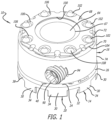
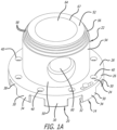
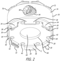
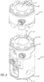
- the spinal implant system can include one or more of an adjustable end cap 10 as depicted in FIGS. 1-6 , and possibly, a spinal implant or spinal implants.
- the spinal implant for example, can be a corpectomy device 12 depicted in FIGS. 7-11 .
- the end cap 10 can be used with additional end caps 10 and/or a spinal implant or spinal implants such as the corpectomy device 12.
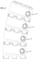
- multiple end caps 10 can be stacked on top of one another, as depicted in FIG. 6 .
- the componentry of the spinal implant system can be assembled outside of the body, in situ within the spine, or a combination of outside and in situ assembly.
- the end cap 10 can be attached to a first end of the corpectomy device 12, and a second end cap 10' (identical to the end cap 10) can be attached to a second end of the corpectomy device 12.
- a spinal implant such as, for example, the corpectomy device 12.
- the spinal implant used with the end cap 10 can be unexpandable and expandable.
- corpectomy devices that are unexpandable can be used with one or more of the end caps 10.
- the dimensions and ultimate angularity of the spinal implant system implanted into a patient can vary at least depending on the size of the spinal implant, on whether the spinal implant is expandable or unexpandable, the number of the end caps utilized, and the angularity afforded by the spinal implant and the one or more end caps.
- the end cap 10 as depicted in FIGS. 1-6 , includes a base portion 14 and a body portion 16.
- the base portion 14 can be attached to the corpectomy device 12, and the body portion 16 can be positioned and repositioned with respect to the base portion 14 to afford adjustable angularity. That is, the body portion 16 is adjustable between different angled orientations with respect to the base portion 14.
- the base portion 14 includes a lower portion 20 and an upper portion 22.
- the lower portion 20 is attachable and detachable to the corpectomy device 12.
- the upper portion 22 is attached to and extends upwardly from the lower portion 20, and the upper portion 22 serves as a pedestal for supporting the body portion 16 on the base portion 14.
- the lower portion 20 includes a plate (or disc) portion 24, and the plate portion 24 includes an upper surface 26 and a lower surface 28.
- Various sidewall portions 30 extend downwardly from the lower surface 28, and at least two of the sidewall portions 30 include tabs 32 formed thereon facilitating the attachment and detachment of the end cap 10 to the second end cap 10' or the corpectomy device 12.
- the sidewall portions 30 are spaced apart from one another and include exterior surfaces 34 and interior surfaces 36.
- the exterior surfaces 34 and an exterior surface 38 of the plate portion 24 can be arcuate.
- the lower surface 28 of plate portion 24 and the interior surfaces 36 of the sidewall portions 30 define a cavity C for receiving a portion of the second end cap 10' or a portion of the corpectomy device 12 therein.
- the tabs 32 facilitate attachment and detachment of the end cap 10 to the portions of the second end cap 10' or the corpectomy device 12 after these portions are received in the cavity C.
- the lower surface 28 of the plate portion 24 and interior surfaces 36 of the sidewall portions 30 are used to contact the portions of the second end cap 10' or the corpectomy device 12 received in the cavity C to resist movement of the end cap 10 with respect thereto.
- the sidewall portions 30 including the tabs 32 can have a degree of resiliency (or springiness) allowing passage of portions of the second end cap 10' or the corpectomy device 12 thereby.
- the sidewall portions including the tabs 32 serve in attaching and detaching the end cap 10 to the second end cap 10' or the corpectomy device 12, and the sidewall portions 30 serve in stabilizing the position of the end cap 10 thereon.
- the plate portion 24 includes various apertures 40 extending between the upper surface 26 and the lower surface 28 that can receive portions of the second end cap 10' or the corpectomy device 12.
- the apertures 40 are spaced apart from one another around the plate portion 24, and the apertures 40 can include engagement surfaces 42 adjacent the lower surface 28 for contacting complementary engagement surfaces on the second end cap 10' or the corpectomy device 12.
- the engagement surfaces 42 can have frusto-conical shapes. Rather than the various apertures 40, various depressions that incorporate the engagement surfaces 42 can be formed in the lower surface 28.
- the upper portion 22 serves as a pedestal for supporting the body portion 16 on the base portion 14.
- the upper portion 22 includes a first end 50, an opposite second end 52, and an axis A 1 extending through the first end 50 and the second end 52.
- the first end 50 is attached to the plate portion 24, and the upper portion 22 extends from the plate portion 24 to the second end 52.
- the upper portion 22 from the first end to adjacent the second end 52 includes an exterior surface portion 54, and at and adjacent the second end 52 includes an exterior surface portion 56.
- the exterior surface portion 54 can be substantially cylindrical, and the exterior surface portion 56 can have a decreasing taper.
- the decreasing taper for example, can be formed by a plurality of steps 58 similar to those disclosed in U.S. Publication No. 2016/0100955 .
- the base portion 14 includes a passage 64 extending therethrough.
- the passage 64 extends through the lower portion 20 and the upper portion 22.
- the passage 64 includes a first opening 66 formed in the lower surface 28 of the plate portion 24 of the lower portion 20, and includes a second opening 67 formed in the exterior surface portion 56 of the second end 52 of the upper portion 22.
- the passage 64 can be filled with bone growth promoting materials.
- the bone growth promoting materials can stimulate bone growth through the spinal implant system.
- the plurality of steps 58 and the interior of the body portion 16 allow for selective positioning of the body portion 16 relative to the base portion 14. As depicted in FIGS. 4A and 4B , such selective positioning affords rotation of the body portion 16 relative to the axis A 1 , and affords different angled orientations of the body portion 16 relative to the base portion 14.
- a top surface 68 of the body portion 16 can be angled at least in the range of ⁇ 10 degrees, if not more, relative to the axis A 1 .
- an axis A 2 of the body portion 16 can be angled at least in the range of ⁇ 10 degrees, if not more, relative to the axis A 1 .
- the body portion 16 can be fixed in position relative to the base portion 14 using a locking element 90 and a protrusion or nub 92 that impinge on a first engagement surface 60 and a second engagement surface 62, respectively, formed on the upper portion 22 similar to that disclosed in U.S. Publication No. 2016/0100955 .
- the body portion 16 includes a sidewall portion 70 and a flange portion 72.
- the sidewall portion 70 includes an exterior surface 74 that can be arcuate, and the radius of curvature of the exterior surface 74 can be similar to the radii of curvatures of the exterior surfaces 34 and the exterior surface 38. As depicted in FIGS. 1 and 2-4 , the exterior surface 74 can be cylindrical.
- the sidewall portion 70 includes a recess 76 formed in the exterior surface 74 adjacent the flange portion 72. As depicted in FIGS. 1 and 2-4 , the recess 76 can be annular.
- the sidewall portion 70 also includes an interior surface 78 defining an interior cavity 80, and the interior cavity 80 is configured to receive a portion of the upper portion 22 of the base portion 14.
- the interior surface 78 includes a lower portion 82 that surrounds a portion the exterior surface portion 54, and the interior surface 78 includes an upper portion 84 for engaging the exterior surface portion 56.
- the lower portion 82 can have a frusto-conical shape, and the upper portion 84 can have a dome shape.
- the frusto-conical shape of the lower portion 82 and the dome shape of the upper portion 84 allow the body portion 16 to rotate on the upper portion 22 relative to the base portion 14 between the above-discussed angles.
- the locking element 90 and the protrusion 92 can be used in fixing the body portion 16 in position relative to base portion 14.
- the locking element 90 can be a fastener such as a set screw received in an aperture 94 extending through the sidewall portion 70 of the body portion 16.
- the aperture 94 includes threads that complement the threads of the set screw 90, and the set screw 90 can be driven through the aperture 94 to impinge on the first engagement surface 60.
- the protrusion 92 can be a nub that extends into the interior cavity 80 from the interior surface 78. The nub 92 can be engaged to the second engagement surface 62.
- the first engagement surface 60 and the second engagement surface 62 can be provided on opposite or approximately opposite sides of the upper portion 22, and the set screw 90 and the nub 92 can be provided on opposite or approximately sides of the body portion.
- impingement of the set screw 90 on the first engagement surface 60 causes impingement of the nub 92 on the second engagement surface 62.
- the upper portion 22 can be clamped between the set screw 90 and the nub 92 by tightening of the set screw 90 to fix the body portion 16 in position relative to the base portion 14.
- the flange portion 72 is configured to both engage bone of the patient and engage portions of the second end cap 10'.
- the flange portion 72 can engage an endplate of the vertebra of the patient, or the flange portion 72 can facilitate attachment of the end cap 10 to the second end cap 10' via receipt thereof in the cavity C of the second end cap 10'.
- the flange portion 72 includes the top surface 68, an aperture 100 through the top surface 68, various protrusions 102 spaced apart from one another around the flange portion 72, and a perimeter surface 104 extending around the top surface 68.
- the aperture 100 ultimately affords access to the passage 64
- the various protrusions 102 extend upwardly from various recesses 106 formed in the top surface 68.
- the protrusions 102 include engagement surfaces 108 for either engaging the bone of the endplate of the patient, or engaging the complementary engagement surfaces 42 of the second end cap 10'.
- the engagement of the protrusions 102 (along with the recesses 106) to the bone of the endplate serves in resisting movement therebetween.
- the engagement of the engagement surfaces 108 of the end cap 10 with the engagement surfaces 42 of the second end cap 10' also serves in resisting movement therebetween.
- the flange portion 72 of the end cap 10 can be received in the cavity C of the second end cap 10'.
- the engagement surfaces 108 of the end cap 10 are engaged to engagement surfaces 42 of the second end cap 10'.
- the top surface 68 of the end cap 10 is contacted with the lower surface 28 of the second end cap 10', portions of the perimeter surface 104 of the end cap 10 are contacted to the interior surfaces 36 of the sidewall portions 30 of the second end cap 10', and the recess 76 of the end cap 10 can receive the tabs 32 of the second end cap 10'.
- the sidewall portions 30 including the tabs 32 have a degree of resiliency. Such resiliency allows the sidewall portions 30 including the tabs 32 to move between a first position and a second position, while being biased in the first position. As such, the sidewall portions 30 including the tabs 32 allow passage of the flange portion 72 thereby via movement thereof from the first position to the second position. Thereafter, the bias thereof moves the sidewall portions 30 including the tabs 32 back into the first position.
- the resiliency of the sidewall portions 30 including the tabs 32 allows the end cap 10 to be rocked (via the application of a rocking force) or snapped (via application of a linear force) into position on the second end cap 10'.
- the tabs 32 can be received in the recess 76 to attach the end cap 10 to the second end cap 10'. Attachment can also be accomplished utilizing attachment mechanisms similar to those disclosed in U.S. Patent No. 9,427,325 .
- a third end cap 10" (identical to the end cap 10) can be attached to the second end cap 10', and a fourth end cap 10′′′ (identical to the end cap 10) to the third end cap 10" in a similar manner to the attachment of the second end cap 10' to the end cap 10.
- various end caps 10 can be stacked on top of one another. The stacking of additional end caps 10 increases the height of the assembly and also increases the potential angularity of the assembly.
- the cavities C of the end cap 10 or the second end cap 10' can receive a first flange portion 110 or a second flange portion 112 of an expandable spinal implant such as, for example, the corpectomy device 12.
- the corpectomy device 12 is similar to that disclosed in U.S. Publication No. 2016/0100955 .
- the overall height of the corpectomy device 12 is adjustable between an unexpanded configuration and an expanded configuration, and at least one end of the corpectomy device includes features affording adjustable angularity.
- an unexpandable spinal implant such a corpectomy device having a fixed height and a fixed angularity could also be used.
- the corpectomy device 12 includes a first end 114 at which the first flange portion 110 is provided, and includes an opposite second end 116 at which the second flange portion 112 is provided.
- a first recess 120 is provided adjacent the first flange portion 110
- a second recess 122 is provided adjacent the second flange portion 112.
- the first flange portion 110, the second flange portion 112, the first recess 120, and the second recess 122 could also be included on a fixed height spinal implant (such as, for example, a corpectomy device) in similar fashion.
- the first flange portion 110 and the second flange portion 112 are similar (if not identical) to the flange portion 72 of the end cap 10.
- FIGS. 10 and 11 depict, for example, the end cap 10 being positioned for attachment to the first flange portion 110. Furthermore, the end cap 10 can be attached to one of the first flange portion 110 and the second flange portion 112, and the second end cap 10' can be attached to the other of the first flange portion 110 and the second flange portion 112. As depicted in FIGS. 10 and 11 , the end cap 10 is attached to the first flange portion 110 and the second end cap 10' is attached to the second flange portion 112.
- the height and angularity of the spinal implant system implanted into a patient can vary at least depending on the size of the corpectomy device, on whether the corpectomy device is expandable or unexpandable, the number of the end caps utilized, and the angularity afforded by the one or more end caps and the corpectomy device.
- the corpectomy device 12 includes a passage 124 extending between the first end 114 and the second end 116 thereof.
- the passage 124 includes a first opening 126 in the first flange portion 110 at the first end 114 and a second opening (not shown) in the second flange portion 112 at the second end 116.
- the passage 124 like the passage 64 of the end cap 10, can be filled with bone growth promoting materials.
- the bone growth promoting materials provided in the passage 64 and the passage 124 can be used to promote bone growth between the vertebral bodies bordering the intervertebral space.
- the bone growth promoting materials can stimulate bone growth through the spinal implant system.
- the spinal implant system can employ one or more of the end caps 10 and a spinal implant such as, for example, the corpectomy device 12 is for implantation into a section of the spine of the patient.
- the intervertebral space can be formed by removal of one or more vertebral bodies and one or more discs, and the spinal implant system is used to bridge the intervertebral space between the vertebral bodies bordering the intervertebral space.
- the spinal implant system of the present invention the distance and the angularity between the vertebral bodies bordering the intervertebral space is determined.
- a corpectomy device 12 having an appropriate height, and one or more of the end caps 10 can be attached to either end of the corpectomy device 12 to provide a height of the spinal implant system sized in accordance with the distance between the vertebral bodies bordering the intervertebral space. Furthermore, angularity of the end caps 10 can be adjusted to accommodate the angularity between the vertebral bodies bordering the intervertebral space.
- the height of the spinal implant system also can be adjusted via use of an expandable, as opposed to an unexpandable, spinal implant, and the angularity of the spinal implant system also can be adjusted using a spinal implants including features affording adjustable angularity.
- the spinal implant system can employ one or more of the end caps 10 and a plurality of spinal implants such as, for example, a plurality of the corpectomy devices.
- a plurality of spinal implants such as, for example, a plurality of the corpectomy devices.
- at least one of the end caps 10 can be used with at least two corpectomy devices.
- the end cap 10 could be positioned between a first one and a second one of the corpectomy devices.
- the end cap 10 could be attached to a first corpectomy device such as, for example, the corpectomy device 12 via receipt of the first flange portion 110 of the corpectomy device 12 in the cavity C of the end cap 10.
- a second corpectomy device could be modified to have structure providing a cavity similar to the cavity C of the end cap 10, and the end cap 10 could be attached to the second corpectomy device via receipt of the flange portion 72 in the cavity of the second corpectomy device.
- the end cap 10 could be modified to include structure providing a second cavity similar to the cavity C instead of the flange 72, and the first flange 110 of the first corpectomy device could be received in the cavity C, and the second flange 112 of the second corpectomy device could be received in the second cavity similar to cavity C.
- the end cap 10 could be modified to include structure providing a second flange similar to flange 72 instead of the cavity C, the first corpectomy device and the second corpectomy device could be modified to have structure providing cavities similar to the cavity C, and the flange 72 could be received in the cavity of the first corpectomy device, and the second flange similar to flange 72 could receive in the cavity of the second corpectomy devices.
- Other types of implants can be similarly modified.
- additional end caps 10 and additional spinal implants could be modified and attached to one another in similar fashion.
Landscapes
- Health & Medical Sciences (AREA)
- Engineering & Computer Science (AREA)
- Biomedical Technology (AREA)
- Orthopedic Medicine & Surgery (AREA)
- Neurology (AREA)
- Heart & Thoracic Surgery (AREA)
- Oral & Maxillofacial Surgery (AREA)
- Transplantation (AREA)
- Cardiology (AREA)
- Vascular Medicine (AREA)
- Life Sciences & Earth Sciences (AREA)
- Animal Behavior & Ethology (AREA)
- General Health & Medical Sciences (AREA)
- Public Health (AREA)
- Veterinary Medicine (AREA)
- Prostheses (AREA)
Claims (7)
- Wirbelsäulenimplantatsystem, umfassend:ein Wirbelsäulenimplantat (12), das ein erstes Ende (114), ein gegenüberliegendes zweites Ende (116), eine Höhe zwischen dem ersten Ende (114) und dem zweiten Ende (116) aufweist, wobei das Wirbelsäulenimplantat (12) einen ersten Flanschabschnitt (110) einschließt, der an dem ersten Ende (114) bereitgestellt ist, einen zweiten Flanschabschnitt (112), der an dem zweiten Ende (116) bereitgestellt ist, eine erste Aussparung (120), die angrenzend an den ersten Flanschabschnitt (110) bereitgestellt ist, und eine zweite Aussparung (122), die angrenzend an den zweiten Flanschabschnitt (112) bereitgestellt ist, aufweist, wobei der erste Flanschabschnitt (110) und der zweite Flanschabschnitt (112) jeweils eine Umfangsoberfläche einschließen, die sich mindestens teilweise entlang des ersten Flanschabschnitts (110) und des zweiten Flanschabschnitts (112) erstreckt; undeine Endkappe (10), die ein erstes Ende und ein gegenüberliegendes zweites Ende aufweist,wobei die Endkappe (10) einen Basisabschnitt (14), der einen unteren Abschnitt (20) und einen oberen Abschnitt (22) einschließt, aufweist, wobei der untere Abschnitt (20) an dem ersten Ende der Endkappe (10) bereitgestellt ist und der obere Abschnitt (22) sich von dem unteren Abschnitt (20) bis angrenzend an das zweite Ende der Endkappe (10) erstreckt,wobei der untere Abschnitt (20) einen Umfang, eine untere Oberfläche (28) und eine Vielzahl von Seitenwandabschnitten (30) einschließt, wobei die Vielzahl von Seitenwandabschnitten (30) angrenzend an den Umfang des unteren Abschnitts (20) voneinander beabstandet sind, wobei mindestens zwei der Vielzahl von Seitenwandabschnitten (30) über einen Abschnitt der unteren Oberfläche (28) voneinander beabstandet sind, wobei die untere Oberfläche (28) und die Innenoberflächen (36) der Vielzahl von Seitenwandabschnitten (30) einen ersten Hohlraum (C) definieren, und die Innenoberflächen (36) von mindestens zwei der Vielzahl von Seitenwandabschnitten (30) jeweils eine Lasche (32), die sich in den ersten Hohlraum (C) erstreckt, einschließen undwobei der obere Abschnitt (22) ein erstes Ende (50), ein gegenüberliegendes zweites Ende (52), eine erste Mittellängsachse (A1), die sich durch das erste Ende (50) und das zweite Ende (52) erstreckt, und einen äußeren Oberflächenabschnitt (56), der sich zwischen dem ersten Ende (50) und dem zweiten Ende (52) erstreckt, wobei das erste Ende (50) des oberen Abschnitts (22) an dem unteren Abschnitt (20) befestigt ist und der äußere Oberflächenabschnitt (56) einen verjüngten Abschnitt angrenzend an das zweite Ende (52) des oberen Abschnitts (22) einschließt,wobei die Endkappe (10) einen Körperabschnitt (16) aufweist, der einen Seitenwandabschnitt (70), einen dritten Flanschabschnitt (72) und eine dritte Aussparung (76) einschließt, aufweist, wobei der Seitenwandabschnitt (70) sich von angrenzend an das erste Ende der Endkappe (10) bis angrenzend an das zweite Ende der Endkappe (10) erstreckt, wobei der dritte Flanschabschnitt (72) an dem zweiten Ende der Endkappe (10) bereitgestellt ist und die dritte Aussparung (76) in dem Seitenwandabschnitt (70) angrenzend an den dritten Flansch (72) bereitgestellt ist, wobei der Seitenwandabschnitt (70) eine zweite Mittellängsachse (A2) aufweist und einen inneren Hohlraum (80) zum Aufnehmen eines Abschnitts des oberen Abschnitts (22) des Basisabschnitts (14) definiert, wobei der innere Hohlraum (80) eine Eingriffsoberfläche (84) darin zum Kontaktieren mindestens eines Abschnitts des verjüngten Abschnitts des oberen Abschnitts (22) des Basisabschnitts (14) aufweist;wobei der Körperabschnitt (16) in Bezug auf den Basisabschnitt (14) durch Anpassen der Position der Eingriffsoberfläche (84) des inneren Hohlraums (80) des Körperabschnitts (16) an dem verjüngten Abschnitt des oberen Abschnitts (22) des Basisabschnitts (14) positionierbar ist; undwobei der erste Hohlraum (C) der Endkappe (10) konfiguriert ist, um einen des ersten Flanschabschnitts (110) des Wirbelsäulenimplantats (12) und des zweiten Flanschabschnitts (112) des Wirbelsäulenimplantats (12) aufzunehmen, wobei die Laschen (32) der Endkappe (10) in einer von der ersten Aussparung (120) und der zweiten Aussparung (122) aufgenommen werden, die dem einen von dem ersten Flansch (110) und dem zweiten Flansch (112) entsprechen, um die Befestigung der Endkappe (10) an dem Wirbelsäulenimplantat (12) zu fördern.
- Wirbelsäulenimplantatsystem nach Anspruch 1, wobei jeder der mindestens zwei der Vielzahl von Seitenwandabschnitten (70), einschließlich der Laschen (32), zwischen einer ersten Position, in der die Laschen (32) in der einen der ersten Aussparung (120) und der zweiten Aussparung (122) aufgenommen sind, und einer zweiten Position, die es dem einen von dem ersten Flanschabschnitt (110) und dem zweiten Flanschabschnitt (112) ermöglicht, dadurch hindurchzugehen, bewegbar ist, wobei die mindestens zwei der Vielzahl von Seitenwandabschnitten (70) jeweils elastisch in die erste Position vorgespannt sind.
- Wirbelsäulenimplantatsystem nach Anspruch 1, wobei die Endkappe (10) an dem Wirbelsäulenimplantat (12) drehbar befestigt ist und durch Drehen des ersten Hohlraums (C) in Bezug auf einen von dem ersten Flansch (110) und dem zweiten Flansch (112) zu einer Drehung fähig ist.
- Wirbelsäulenimplantatsystem nach Anspruch 1, wobei das Wirbelsäulenimplantat (12) zwischen einer nicht expandierten Konfiguration und einer expandierten Konfiguration expandierbar ist, wobei die Expansion des Wirbelsäulenimplantats (12) die Höhe davon vergrößert.
- Wirbelsäulenimplantatsystem nach Anspruch 1, wobei der Seitenwandabschnitt (70) des Körperabschnitts (16) eine Außenoberfläche (74) und eine Öffnung (94) einschließt, die sich von der Außenoberfläche (74) zu dem Innenhohlraum (80) erstreckt, und die Endkappe (10) ferner ein Verbindungsmittel (90) umfasst, das in der Öffnung (94) zum Auftreffen auf den oberen Abschnitt (22) des Basisabschnitts (14) aufgenommen ist, wobei das Auftreffen des Verbindungsmittels (90) auf den oberen Abschnitt (22) des Basisabschnitts (14) dazu dient, die Position des Körperabschnitts (16) in Bezug auf den Basisabschnitt (14) zu fixieren.
- Wirbelsäulenimplantatsystem nach Anspruch 5, wobei der dritte Flanschabschnitt (72) eine obere Oberfläche (68) einschließt und die obere Oberfläche (68) des dritten Flanschabschnitts (72) relativ zu der Mittellängsachse (A1) des Körperabschnitts (16) um mindestens ± 10 Grad durch Positionieren des Körperabschnitts (16) relativ zu dem Basisabschnitt (14) schwenkbar ist.
- Wirbelsäulenimplantatsystem nach Anspruch 5, wobei die zweite Mittellängsachse (A2) relativ zu der ersten Mittellängsachse (A1) um mindestens ± 10 Grad durch Positionieren des Körperabschnitts (16) relativ zu dem Basisabschnitt (14) bewegbar ist.
Applications Claiming Priority (2)
| Application Number | Priority Date | Filing Date | Title |
|---|---|---|---|
| US15/896,936 US10987229B2 (en) | 2018-02-14 | 2018-02-14 | Spinal implant system |
| PCT/US2019/017576 WO2019160831A1 (en) | 2018-02-14 | 2019-02-12 | Spinal implant system |
Publications (3)
| Publication Number | Publication Date |
|---|---|
| EP3752102A1 EP3752102A1 (de) | 2020-12-23 |
| EP3752102A4 EP3752102A4 (de) | 2021-11-10 |
| EP3752102B1 true EP3752102B1 (de) | 2025-03-26 |
Family
ID=67540656
Family Applications (1)
| Application Number | Title | Priority Date | Filing Date |
|---|---|---|---|
| EP19754596.5A Active EP3752102B1 (de) | 2018-02-14 | 2019-02-12 | Wirbelsäulenimplantatsystem |
Country Status (6)
| Country | Link |
|---|---|
| US (3) | US10987229B2 (de) |
| EP (1) | EP3752102B1 (de) |
| CN (1) | CN111655202B (de) |
| AU (1) | AU2019220570A1 (de) |
| CA (1) | CA3091239A1 (de) |
| WO (1) | WO2019160831A1 (de) |
Families Citing this family (6)
| Publication number | Priority date | Publication date | Assignee | Title |
|---|---|---|---|---|
| US10692243B2 (en) * | 2017-12-03 | 2020-06-23 | Facebook, Inc. | Optimizations for dynamic object instance detection, segmentation, and structure mapping |
| US10987229B2 (en) * | 2018-02-14 | 2021-04-27 | Warsaw Orthopedic, Inc. | Spinal implant system |
| US10923860B2 (en) * | 2019-02-25 | 2021-02-16 | J.S.T. Corporation | Method for shielding and grounding a connector assembly from electromagnetic interference (EMI) using conductive seal and conductive housing |
| US12310855B2 (en) | 2021-09-09 | 2025-05-27 | Warsaw Orthopedic, Inc. | End cap and bone screw for use therewith |
| CN115568985A (zh) * | 2022-09-09 | 2023-01-06 | 广东施泰宝医疗科技有限公司 | 一种钛笼用的可选角度填骨装置 |
| US12542780B2 (en) | 2022-12-30 | 2026-02-03 | Mastercard Technologies Canada ULC | Sessions correlation for multiple device authentication |
Family Cites Families (24)
| Publication number | Priority date | Publication date | Assignee | Title |
|---|---|---|---|---|
| FR2817463B1 (fr) * | 2000-12-05 | 2003-04-04 | Stryker Spine Sa | Implant intersomatique rachidien distractable in-situ |
| US6808538B2 (en) * | 2002-03-15 | 2004-10-26 | Stryker Spine | Vertebral body spacer having variable wedged endplates |
| DE10218093B4 (de) * | 2002-04-23 | 2005-04-07 | Signus Medizintechnik Gmbh | Wirbelsäulenimplantat |
| DE10242331B4 (de) | 2002-09-12 | 2005-10-20 | Biedermann Motech Gmbh | Platzhalter für Wirbelkörper oder Bandscheiben |
| US7192447B2 (en) | 2002-12-19 | 2007-03-20 | Synthes (Usa) | Intervertebral implant |
| US7544208B1 (en) | 2004-05-03 | 2009-06-09 | Theken Spine, Llc | Adjustable corpectomy apparatus |
| US7674296B2 (en) | 2005-04-21 | 2010-03-09 | Globus Medical, Inc. | Expandable vertebral prosthesis |
| KR20090096609A (ko) | 2006-11-29 | 2009-09-11 | 서지크래프트 리미티드 | 정형 외과용 임플란트 및 보철물 |
| US8197546B2 (en) | 2007-11-27 | 2012-06-12 | Ortho Innovations, Llc | Corpectomy implant |
| TWI383772B (zh) | 2007-11-30 | 2013-02-01 | 趙振綱 | Adjustable artificial vertebral body stent |
| US8353961B2 (en) | 2008-02-07 | 2013-01-15 | K2M, Inc. | Expandable vertebral device with cam lock |
| US9687357B2 (en) | 2009-03-12 | 2017-06-27 | Nuvasive, Inc. | Vertebral body replacement |
| US8202321B2 (en) | 2009-06-17 | 2012-06-19 | Ulrich Gmbh & Co. Kg | Implant |
| US8211178B2 (en) * | 2009-06-18 | 2012-07-03 | Warsaw Orthopedic | Intervertebral implant with a pivoting end cap |
| US8858636B2 (en) | 2010-04-09 | 2014-10-14 | DePuy Synthes Products, LLC | Intervertebral implant |
| US9579211B2 (en) * | 2010-04-12 | 2017-02-28 | Globus Medical, Inc. | Expandable vertebral implant |
| US8945228B2 (en) | 2012-11-15 | 2015-02-03 | DePuy Synthes Products, LLC | Endplate for a vertebral implant |
| US9138324B2 (en) * | 2013-01-24 | 2015-09-22 | Warsaw Orthopedic, Inc. | Expandable spinal implant system and method |
| US9427325B2 (en) | 2013-07-26 | 2016-08-30 | Warsaw Orthopedic, Inc. | Interbody implant and method |
| US9974663B2 (en) * | 2014-10-09 | 2018-05-22 | Warsaw Orthopedic, Inc. | Spinal implant system and method |
| US9801730B2 (en) | 2014-12-23 | 2017-10-31 | Globus Medical, Inc. | Vertebral implants and methods for installation thereof |
| EP3141222B1 (de) * | 2015-09-08 | 2019-02-06 | Ulrich GmbH & Co. KG | Implantat |
| EP3349695B1 (de) | 2015-09-18 | 2020-11-18 | K2M, Inc. | Korpektomievorrichtung |
| US10987229B2 (en) * | 2018-02-14 | 2021-04-27 | Warsaw Orthopedic, Inc. | Spinal implant system |
-
2018
- 2018-02-14 US US15/896,936 patent/US10987229B2/en active Active
-
2019
- 2019-02-12 WO PCT/US2019/017576 patent/WO2019160831A1/en not_active Ceased
- 2019-02-12 CA CA3091239A patent/CA3091239A1/en not_active Abandoned
- 2019-02-12 CN CN201980010036.9A patent/CN111655202B/zh active Active
- 2019-02-12 AU AU2019220570A patent/AU2019220570A1/en not_active Abandoned
- 2019-02-12 EP EP19754596.5A patent/EP3752102B1/de active Active
-
2021
- 2021-03-12 US US17/200,496 patent/US11701237B2/en active Active
-
2023
- 2023-03-31 US US18/129,558 patent/US11992420B2/en active Active
Also Published As
| Publication number | Publication date |
|---|---|
| WO2019160831A1 (en) | 2019-08-22 |
| US20190247199A1 (en) | 2019-08-15 |
| US20230240859A1 (en) | 2023-08-03 |
| US10987229B2 (en) | 2021-04-27 |
| US11701237B2 (en) | 2023-07-18 |
| AU2019220570A1 (en) | 2020-07-23 |
| CN111655202B (zh) | 2023-09-29 |
| CA3091239A1 (en) | 2019-08-22 |
| US20210196476A1 (en) | 2021-07-01 |
| CN111655202A (zh) | 2020-09-11 |
| US11992420B2 (en) | 2024-05-28 |
| EP3752102A4 (de) | 2021-11-10 |
| EP3752102A1 (de) | 2020-12-23 |
Similar Documents
| Publication | Publication Date | Title |
|---|---|---|
| US11992420B2 (en) | Spinal implant system | |
| US9532807B2 (en) | Anchoring member with safety ring | |
| EP2319465B1 (de) | Künstliche Zwischenwirbelscheibe mit einem geschlitzten Tellerfeder-Kraftrückstellungselement | |
| US8986384B2 (en) | Method for stabilizing spine | |
| US20040210312A1 (en) | Implant for insertion between vertebrae of the spinal column | |
| US6764515B2 (en) | Intervertebral spacer device utilizing a spirally slotted belleville washer and a rotational mounting | |
| US7563285B2 (en) | Artificial intervertebral disc utilizing a ball joint coupling | |
| US6863688B2 (en) | Intervertebral spacer device utilizing a spirally slotted belleville washer having radially spaced concentric grooves | |
| EP1379200B1 (de) | Einstellbare montageanordnung zur befestigung eines gegenstandes | |
| KR20000065181A (ko) | 페디클스크루와함께사용하기위한단일잠금캡 | |
| US9763714B2 (en) | Medical device locking mechanisms and related methods and systems | |
| US20020111684A1 (en) | Intervertebral spacer device utilizing a belleville washer having radially spaced concentric grooves | |
| US20050137597A1 (en) | Dynamic cervical plates and cervical plate constructs | |
| US20090177283A9 (en) | Intervertebral spacer device utilizing a spirally slotted belleville washer and a rotational mounting | |
| US7892286B2 (en) | Expandable push-in orthopedic implant | |
| US20040204762A1 (en) | Intervertebral spacer device utilizing a spirally slotted belleville washer having radially spaced concentric grooves | |
| EP2244671A1 (de) | Intervertebrale prothesescheibe mit stossdämpfendem, mit scheibenfedern ausgebildetem kern | |
| WO2008022202A2 (en) | Spinal implant | |
| US8092539B2 (en) | Intervertebral spacer device having a belleville washer with concentric grooves | |
| EP4147679B1 (de) | Endkappe und knochenschraube zur verwendung damit | |
| US11154339B2 (en) | Bone stabilization implant with anchor screw locking element | |
| WO2003032802A2 (en) | Intervertebral spacer device having an arched spring element | |
| US20050125064A1 (en) | Intervertebral spacer device | |
| WO2003028583A2 (en) | Artificial intervertebral disc having a grooved belleville washer force restoring element |
Legal Events
| Date | Code | Title | Description |
|---|---|---|---|
| STAA | Information on the status of an ep patent application or granted ep patent |
Free format text: STATUS: THE INTERNATIONAL PUBLICATION HAS BEEN MADE |
|
| PUAI | Public reference made under article 153(3) epc to a published international application that has entered the european phase |
Free format text: ORIGINAL CODE: 0009012 |
|
| STAA | Information on the status of an ep patent application or granted ep patent |
Free format text: STATUS: REQUEST FOR EXAMINATION WAS MADE |
|
| 17P | Request for examination filed |
Effective date: 20200703 |
|
| AK | Designated contracting states |
Kind code of ref document: A1 Designated state(s): AL AT BE BG CH CY CZ DE DK EE ES FI FR GB GR HR HU IE IS IT LI LT LU LV MC MK MT NL NO PL PT RO RS SE SI SK SM TR |
|
| AX | Request for extension of the european patent |
Extension state: BA ME |
|
| DAV | Request for validation of the european patent (deleted) | ||
| DAX | Request for extension of the european patent (deleted) | ||
| A4 | Supplementary search report drawn up and despatched |
Effective date: 20211008 |
|
| RIC1 | Information provided on ipc code assigned before grant |
Ipc: A61F 2/30 20060101ALI20211004BHEP Ipc: A61B 17/70 20060101ALI20211004BHEP Ipc: A61F 2/44 20060101AFI20211004BHEP |
|
| GRAP | Despatch of communication of intention to grant a patent |
Free format text: ORIGINAL CODE: EPIDOSNIGR1 |
|
| STAA | Information on the status of an ep patent application or granted ep patent |
Free format text: STATUS: GRANT OF PATENT IS INTENDED |
|
| INTG | Intention to grant announced |
Effective date: 20241030 |
|
| GRAS | Grant fee paid |
Free format text: ORIGINAL CODE: EPIDOSNIGR3 |
|
| GRAA | (expected) grant |
Free format text: ORIGINAL CODE: 0009210 |
|
| STAA | Information on the status of an ep patent application or granted ep patent |
Free format text: STATUS: THE PATENT HAS BEEN GRANTED |
|
| AK | Designated contracting states |
Kind code of ref document: B1 Designated state(s): AL AT BE BG CH CY CZ DE DK EE ES FI FR GB GR HR HU IE IS IT LI LT LU LV MC MK MT NL NO PL PT RO RS SE SI SK SM TR |
|
| REG | Reference to a national code |
Ref country code: GB Ref legal event code: FG4D |
|
| REG | Reference to a national code |
Ref country code: CH Ref legal event code: EP |
|
| REG | Reference to a national code |
Ref country code: DE Ref legal event code: R096 Ref document number: 602019067792 Country of ref document: DE |
|
| REG | Reference to a national code |
Ref country code: IE Ref legal event code: FG4D |
|
| PG25 | Lapsed in a contracting state [announced via postgrant information from national office to epo] |
Ref country code: RS Free format text: LAPSE BECAUSE OF FAILURE TO SUBMIT A TRANSLATION OF THE DESCRIPTION OR TO PAY THE FEE WITHIN THE PRESCRIBED TIME-LIMIT Effective date: 20250626 |
|
| PG25 | Lapsed in a contracting state [announced via postgrant information from national office to epo] |
Ref country code: FI Free format text: LAPSE BECAUSE OF FAILURE TO SUBMIT A TRANSLATION OF THE DESCRIPTION OR TO PAY THE FEE WITHIN THE PRESCRIBED TIME-LIMIT Effective date: 20250326 |
|
| REG | Reference to a national code |
Ref country code: LT Ref legal event code: MG9D |
|
| PG25 | Lapsed in a contracting state [announced via postgrant information from national office to epo] |
Ref country code: NO Free format text: LAPSE BECAUSE OF FAILURE TO SUBMIT A TRANSLATION OF THE DESCRIPTION OR TO PAY THE FEE WITHIN THE PRESCRIBED TIME-LIMIT Effective date: 20250626 |
|
| PG25 | Lapsed in a contracting state [announced via postgrant information from national office to epo] |
Ref country code: HR Free format text: LAPSE BECAUSE OF FAILURE TO SUBMIT A TRANSLATION OF THE DESCRIPTION OR TO PAY THE FEE WITHIN THE PRESCRIBED TIME-LIMIT Effective date: 20250326 |
|
| PG25 | Lapsed in a contracting state [announced via postgrant information from national office to epo] |
Ref country code: LV Free format text: LAPSE BECAUSE OF FAILURE TO SUBMIT A TRANSLATION OF THE DESCRIPTION OR TO PAY THE FEE WITHIN THE PRESCRIBED TIME-LIMIT Effective date: 20250326 |
|
| PG25 | Lapsed in a contracting state [announced via postgrant information from national office to epo] |
Ref country code: GR Free format text: LAPSE BECAUSE OF FAILURE TO SUBMIT A TRANSLATION OF THE DESCRIPTION OR TO PAY THE FEE WITHIN THE PRESCRIBED TIME-LIMIT Effective date: 20250627 Ref country code: BG Free format text: LAPSE BECAUSE OF FAILURE TO SUBMIT A TRANSLATION OF THE DESCRIPTION OR TO PAY THE FEE WITHIN THE PRESCRIBED TIME-LIMIT Effective date: 20250326 |
|
| REG | Reference to a national code |
Ref country code: NL Ref legal event code: MP Effective date: 20250326 |
|
| PG25 | Lapsed in a contracting state [announced via postgrant information from national office to epo] |
Ref country code: NL Free format text: LAPSE BECAUSE OF FAILURE TO SUBMIT A TRANSLATION OF THE DESCRIPTION OR TO PAY THE FEE WITHIN THE PRESCRIBED TIME-LIMIT Effective date: 20250326 |
|
| PG25 | Lapsed in a contracting state [announced via postgrant information from national office to epo] |
Ref country code: SE Free format text: LAPSE BECAUSE OF FAILURE TO SUBMIT A TRANSLATION OF THE DESCRIPTION OR TO PAY THE FEE WITHIN THE PRESCRIBED TIME-LIMIT Effective date: 20250326 |
|
| REG | Reference to a national code |
Ref country code: AT Ref legal event code: MK05 Ref document number: 1778314 Country of ref document: AT Kind code of ref document: T Effective date: 20250326 |
|
| PG25 | Lapsed in a contracting state [announced via postgrant information from national office to epo] |
Ref country code: SM Free format text: LAPSE BECAUSE OF FAILURE TO SUBMIT A TRANSLATION OF THE DESCRIPTION OR TO PAY THE FEE WITHIN THE PRESCRIBED TIME-LIMIT Effective date: 20250326 |
|
| PG25 | Lapsed in a contracting state [announced via postgrant information from national office to epo] |
Ref country code: ES Free format text: LAPSE BECAUSE OF FAILURE TO SUBMIT A TRANSLATION OF THE DESCRIPTION OR TO PAY THE FEE WITHIN THE PRESCRIBED TIME-LIMIT Effective date: 20250326 Ref country code: PT Free format text: LAPSE BECAUSE OF FAILURE TO SUBMIT A TRANSLATION OF THE DESCRIPTION OR TO PAY THE FEE WITHIN THE PRESCRIBED TIME-LIMIT Effective date: 20250728 |
|
| PG25 | Lapsed in a contracting state [announced via postgrant information from national office to epo] |
Ref country code: PL Free format text: LAPSE BECAUSE OF FAILURE TO SUBMIT A TRANSLATION OF THE DESCRIPTION OR TO PAY THE FEE WITHIN THE PRESCRIBED TIME-LIMIT Effective date: 20250326 Ref country code: IT Free format text: LAPSE BECAUSE OF FAILURE TO SUBMIT A TRANSLATION OF THE DESCRIPTION OR TO PAY THE FEE WITHIN THE PRESCRIBED TIME-LIMIT Effective date: 20250326 |
|
| PG25 | Lapsed in a contracting state [announced via postgrant information from national office to epo] |
Ref country code: AT Free format text: LAPSE BECAUSE OF FAILURE TO SUBMIT A TRANSLATION OF THE DESCRIPTION OR TO PAY THE FEE WITHIN THE PRESCRIBED TIME-LIMIT Effective date: 20250326 |
|
| PG25 | Lapsed in a contracting state [announced via postgrant information from national office to epo] |
Ref country code: EE Free format text: LAPSE BECAUSE OF FAILURE TO SUBMIT A TRANSLATION OF THE DESCRIPTION OR TO PAY THE FEE WITHIN THE PRESCRIBED TIME-LIMIT Effective date: 20250326 |
|
| PG25 | Lapsed in a contracting state [announced via postgrant information from national office to epo] |
Ref country code: RO Free format text: LAPSE BECAUSE OF FAILURE TO SUBMIT A TRANSLATION OF THE DESCRIPTION OR TO PAY THE FEE WITHIN THE PRESCRIBED TIME-LIMIT Effective date: 20250326 |
|
| PG25 | Lapsed in a contracting state [announced via postgrant information from national office to epo] |
Ref country code: SK Free format text: LAPSE BECAUSE OF FAILURE TO SUBMIT A TRANSLATION OF THE DESCRIPTION OR TO PAY THE FEE WITHIN THE PRESCRIBED TIME-LIMIT Effective date: 20250326 |
|
| PG25 | Lapsed in a contracting state [announced via postgrant information from national office to epo] |
Ref country code: IS Free format text: LAPSE BECAUSE OF FAILURE TO SUBMIT A TRANSLATION OF THE DESCRIPTION OR TO PAY THE FEE WITHIN THE PRESCRIBED TIME-LIMIT Effective date: 20250726 |
|
| REG | Reference to a national code |
Ref country code: DE Ref legal event code: R097 Ref document number: 602019067792 Country of ref document: DE |
|
| PG25 | Lapsed in a contracting state [announced via postgrant information from national office to epo] |
Ref country code: DK Free format text: LAPSE BECAUSE OF FAILURE TO SUBMIT A TRANSLATION OF THE DESCRIPTION OR TO PAY THE FEE WITHIN THE PRESCRIBED TIME-LIMIT Effective date: 20250326 |
|
| PG25 | Lapsed in a contracting state [announced via postgrant information from national office to epo] |
Ref country code: CZ Free format text: LAPSE BECAUSE OF FAILURE TO SUBMIT A TRANSLATION OF THE DESCRIPTION OR TO PAY THE FEE WITHIN THE PRESCRIBED TIME-LIMIT Effective date: 20250326 |
|
| PLBE | No opposition filed within time limit |
Free format text: ORIGINAL CODE: 0009261 |
|
| STAA | Information on the status of an ep patent application or granted ep patent |
Free format text: STATUS: NO OPPOSITION FILED WITHIN TIME LIMIT |
|
| REG | Reference to a national code |
Ref country code: CH Ref legal event code: L10 Free format text: ST27 STATUS EVENT CODE: U-0-0-L10-L00 (AS PROVIDED BY THE NATIONAL OFFICE) Effective date: 20260211 |
|
| 26N | No opposition filed |
Effective date: 20260105 |
|
| PGFP | Annual fee paid to national office [announced via postgrant information from national office to epo] |
Ref country code: DE Payment date: 20260121 Year of fee payment: 8 |
|
| PGFP | Annual fee paid to national office [announced via postgrant information from national office to epo] |
Ref country code: FR Payment date: 20260121 Year of fee payment: 8 |