EP3752069B1 - Ultraschallgerät zur effizienten mechanischen applikation von ultraschallwellen - Google Patents
Ultraschallgerät zur effizienten mechanischen applikation von ultraschallwellen Download PDFInfo
- Publication number
- EP3752069B1 EP3752069B1 EP19754488.5A EP19754488A EP3752069B1 EP 3752069 B1 EP3752069 B1 EP 3752069B1 EP 19754488 A EP19754488 A EP 19754488A EP 3752069 B1 EP3752069 B1 EP 3752069B1
- Authority
- EP
- European Patent Office
- Prior art keywords
- ultrasound
- transducer
- ultrasound transducer
- motion
- actuator
- Prior art date
- Legal status (The legal status is an assumption and is not a legal conclusion. Google has not performed a legal analysis and makes no representation as to the accuracy of the status listed.)
- Active
Links
Images

Classifications
-
- A—HUMAN NECESSITIES
- A61—MEDICAL OR VETERINARY SCIENCE; HYGIENE
- A61N—ELECTROTHERAPY; MAGNETOTHERAPY; RADIATION THERAPY; ULTRASOUND THERAPY
- A61N7/00—Ultrasound therapy
-
- A—HUMAN NECESSITIES
- A61—MEDICAL OR VETERINARY SCIENCE; HYGIENE
- A61N—ELECTROTHERAPY; MAGNETOTHERAPY; RADIATION THERAPY; ULTRASOUND THERAPY
- A61N7/00—Ultrasound therapy
- A61N7/02—Localised ultrasound hyperthermia
-
- A—HUMAN NECESSITIES
- A61—MEDICAL OR VETERINARY SCIENCE; HYGIENE
- A61N—ELECTROTHERAPY; MAGNETOTHERAPY; RADIATION THERAPY; ULTRASOUND THERAPY
- A61N7/00—Ultrasound therapy
- A61N2007/0004—Applications of ultrasound therapy
-
- A—HUMAN NECESSITIES
- A61—MEDICAL OR VETERINARY SCIENCE; HYGIENE
- A61N—ELECTROTHERAPY; MAGNETOTHERAPY; RADIATION THERAPY; ULTRASOUND THERAPY
- A61N7/00—Ultrasound therapy
- A61N2007/0004—Applications of ultrasound therapy
- A61N2007/0008—Destruction of fat cells
-
- A—HUMAN NECESSITIES
- A61—MEDICAL OR VETERINARY SCIENCE; HYGIENE
- A61N—ELECTROTHERAPY; MAGNETOTHERAPY; RADIATION THERAPY; ULTRASOUND THERAPY
- A61N7/00—Ultrasound therapy
- A61N2007/0004—Applications of ultrasound therapy
- A61N2007/0013—Fracture healing
-
- A—HUMAN NECESSITIES
- A61—MEDICAL OR VETERINARY SCIENCE; HYGIENE
- A61N—ELECTROTHERAPY; MAGNETOTHERAPY; RADIATION THERAPY; ULTRASOUND THERAPY
- A61N7/00—Ultrasound therapy
- A61N2007/0004—Applications of ultrasound therapy
- A61N2007/0017—Wound healing
-
- A—HUMAN NECESSITIES
- A61—MEDICAL OR VETERINARY SCIENCE; HYGIENE
- A61N—ELECTROTHERAPY; MAGNETOTHERAPY; RADIATION THERAPY; ULTRASOUND THERAPY
- A61N7/00—Ultrasound therapy
- A61N2007/0004—Applications of ultrasound therapy
- A61N2007/0021—Neural system treatment
-
- A—HUMAN NECESSITIES
- A61—MEDICAL OR VETERINARY SCIENCE; HYGIENE
- A61N—ELECTROTHERAPY; MAGNETOTHERAPY; RADIATION THERAPY; ULTRASOUND THERAPY
- A61N7/00—Ultrasound therapy
- A61N2007/0004—Applications of ultrasound therapy
- A61N2007/0034—Skin treatment
-
- A—HUMAN NECESSITIES
- A61—MEDICAL OR VETERINARY SCIENCE; HYGIENE
- A61N—ELECTROTHERAPY; MAGNETOTHERAPY; RADIATION THERAPY; ULTRASOUND THERAPY
- A61N7/00—Ultrasound therapy
- A61N2007/0073—Ultrasound therapy using multiple frequencies
-
- A—HUMAN NECESSITIES
- A61—MEDICAL OR VETERINARY SCIENCE; HYGIENE
- A61N—ELECTROTHERAPY; MAGNETOTHERAPY; RADIATION THERAPY; ULTRASOUND THERAPY
- A61N7/00—Ultrasound therapy
- A61N2007/0086—Beam steering
- A61N2007/0091—Beam steering with moving parts, e.g. transducers, lenses, reflectors
Definitions
- the present invention relates to cosmetic treatment apparatuses. More particularly, to an ultrasound apparatus used in various treatment applications.
- Ultrasound waves are applied to a human body via a hand-held device or a stationary, fixed positioned device, directly touching the treated area of the human body. What is needed is a convenient, easy to use, and comfortable means for applying the ultrasound waves efficiently.
- DE3227624 describes a solely stationary diagnostic ultrasound system, where the positioning accuracy is a primary requirement.
- the movement is performed in near zero friction environment achieved within a liquid filled enclosure where the ultrasound head flows with no direct contact towards any surface.
- the whole system is adapted to perform a diagnosis on a specific body part.
- the publication further discloses a "Full azimuthal angular rotation of +180 degrees", but not a continues rotation, since the electric wiring of the system dictates the limit of rotation. Therefore, the described system is limited mechanically, and too bulky and weighty to make a portable implementation possible.
- US2015297182 discloses a mechanically rotating intravascular ultrasound probe.
- the publication discloses a forward-looking mechanically rotating intravascular ultrasound probe having a small volume, a high image resolution and good imaging stability.
- the intravascular ultrasound probe includes a catheter, an ultrasonic transducer disposed at a front end of a cavity of the catheter and a driving apparatus that drives the ultrasonic transducer to rotate mechanically.
- the driving apparatus is a micro motor disposed in the cavity of the catheter, including a rotor and a stator.
- the ultrasonic transducer is installed on top of the rotor and electrically connected to the rotor, and the rotor is also electrically connected to the stator.
- the present invention relates to an ultrasound apparatus for efficiently applying ultrasound waves over a treated area by mechanically moving the ultrasound transducer comprising: (a) an ultrasound transducer, connected by wiring, for dispersing ultrasound waves; (b) a shaft for holding said transducer; (c) an electric actuator for spinning a crank, wherein said shaft is eccentrically attached to said crank for rotatably whirling said transducer in circles; (d) a stabilizer for leading said wiring of said ultrasound transducer, and for holding said shaft; (e) a first linear bearing for guiding a part of said stabilizer while said part of the stabilizer slides in said linear bearing wherein said stabilizer holds said shaft in a position normal to said first linear bearing for reducing the twisting of said wiring, of said ultrasound transducer, when said actuator whirls said transducer; and (f) a control unit, logically connected to said electric actuator, capable of receiving instructions, from the user, and capable of controlling the whirling of said ultrasound transducer, by controlling said electric actuator,
- the apparatus further comprises a friction reducer and a second linear bearing for protecting the wiring and guiding it through a rectifying mechanism, when the actuator whirls said transducer.
- a single cable provides a continuous electrical connection from the input connector of the apparatus to the moving ultrasound transducer for making a number of turns without causing damage to said cable.
- the electric actuator is driven by an electronic circuitry or by directly applied power, for whirling the ultrasound transducer in at least one motion type such as circular motion, linear motion, angular motion, spin motion, vibration, in at least one direction or combination of said directions and motion type patterns.
- a motion type such as circular motion, linear motion, angular motion, spin motion, vibration, in at least one direction or combination of said directions and motion type patterns.
- the apparatus further comprises a connector having at least one BNC connectors for connecting to said ultrasound apparatus, where the whole connector assembly, including non-BNC type of contacts are held in place by utilizing the BNC locking mechanism.
- the apparatus may be embodied in a standalone device or may be incorporated into a larger more comprehensive machinery.
- the apparatus further comprising a coupler implemented for changing speed, pattern, torque or amplitude of the motion of the ultrasound transducer
- the ultrasound transducer is directly attached to said electric actuator.
- the apparatus is used to avoid burns caused by the high-power ultrasound applied for a longer than necessary time to the same spot of the treated area.
- the electrically driven ultrasound transducer is used to increase the blood flow in the treated area due to ability to perform motions at the speed amplitude and pattern impossible to perform manually.
- the electrically driven ultrasound transducer moves in certain types of motions, that generate its own low frequency waves, which in coherence with the main ultrasound carrier frequency produces more effective and more penetrative pulses not producible by a single frequency source
- the electrically driven ultrasound transducer reduces the hardship of the manual motion during the treatment process.
- ultrasound waves may be used in wound treatment, ulcer treatment, pain relief, blood flow stimulation, body shaping, fat reduction, cellulite reduction, skin treatment and other applications for cosmetic or medical treatment.
- Ultrasound waves may be applied to the patient via a hand-held device or a stationary, fixed positioned device, by directly touching the skin of the treated area of the body.
- the Effective Radiating Area (ERA) of the ultrasound transducer is very slim.
- the transducer needs to be moved within a constant speed throughout the treated area.
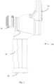
- Fig. 1 is a diagram of a hand-held ultrasound apparatus for applying the ultrasound waves efficiently, according to an embodiment of the invention.
- the apparatus 100 may be a hand-held ultrasound apparatus having a transducer 40 that may be whirled.
- the transducer 40 may be whirled by an electric actuator, such as described in relation to Fig. 2 , for example.
- an electric actuator such as described in relation to Fig. 2 , for example.
- the transducer 40 efficiently disperses the ultrasound waves over an area larger than the transducer's initial ERA.
- One of the features of the described apparatus is to provide a continuous electrical connectivity to the ultrasound transducer 40 while allowing it to make an endless number of turns in a circular pattern without excessive distortion of the electrical conductor.
- the driving electrical signal is usually formed as an RF signal of a high power, as therapeutic ultrasound may require up to tens of Watts to be applied.
- the conduction of such a signal presents an additional problem caused by the nature of the RF cables, which require undisturbed coaxiality of the conductors within.
- the implementation of the sliding contacts may pose an engineering challenge in terms of cost and reliability.
- the simplest and the most reliable way would be utilization of the basic cable without any additional contacts.
- the following mechanism description enables a single cable connectivity between the fixed input end, e.g. connection point 99 in Fig. 1 , and the moving end, e.g. the transducer 40, where the parameters of distortion of the cable could be calculated and adjusted as required.
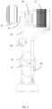
- Fig. 2 is a diagram of some of the inner parts of the ultrasound apparatus, according to an embodiment of the invention.
- the ultrasound transducer 40 as described in relations to Fig. 1 , may have a stainless-steel cover with a PZT807 piezoelectric crystal, or any other ultrasound transducer capable of directing ultrasound waves for human treatment.
- the ultrasound transducer 40 may be connected by wiring.
- the wiring may be an RF cable or any other wiring capable of transferring the electric signals to the transducer 40.
- the ultrasound transducer 40 may be whirled by the electric actuator 10.
- the actuator 10 may be an electric motor, e.g.
- the actuator 10 may whirl the transducer 40 in a circular pattern in any direction or in any other angular pattern. In an embodiment, the actuator 10 may whirl the transducer 40 in one direction and then switch the direction of rotation of the actuator 10 before completing the whole circle. In other embodiments, the actuator 10 may vibrate the transducer 40 by rapidly changing the actuators direction of rotation. Combinations of the vibrations and rotations are also possible according to other embodiments.
- the actuator 10 may spin a crank 60, where the crank 60 has a shaft 62 which is attached pivotally and eccentrically, for rotatably whirling the transducer 40.
- the transducer 40 may be attached to the shaft 62.
- the crank 60 may spin as well with its eccentrically placed shaft 62 making circular movements, which whirls the transducer 40 in circles.
- the actuator's shaft 62 spins, it may commit a circular motion around the actuator's 10 center axis which may whirl the transducer in the same circular pattern.
- the transducer 40 will be whirled in circular pattern in any direction or any other angular pattern by switching direction of rotation of the actuator 10 before completing the whole circle, or vibrate, by rapidly changing the actuator's direction of rotation.
- combination of the vibration and rotation is possible as well.
- the proper displacement of axes i.e. the axis of the shaft 62 and the axis of the actuator 10, will allow to move the transducer in a circular pattern without overlapping the ultrasound beam focus zone, thus increasing the equality of the energy applied to the whole treated area.
- the apparatus 100 may also have a stabilizer 50 which may be used to stabilize the angle of the transducer 40, when the actuator 10 spins and whirls the transducer 40.
- the stabilizer 50 may be a hollow tube made of metal, or any other rigid material, for leading the wiring of the ultrasound transducer 40.
- the top part of stabilizer 50 is inserted into the shaft 62 and attached within the shaft 62.
- the stabilizer 50 may hold the shaft, and the transducer 40, in the position normal to the first linear bearing 90 which guides the stabilizer 50 at the bottom, thus reducing the twisting of the wiring which is attached to the ultrasound transducer 40.
- the first linear bearing 90 is held within the apparatus cover by its axis 91 thus said bearing is capable of committing an angular movement around said axis 91. While the stabilizer 50, at its top side, repeats the circular motions committed by the shaft 62, the angular movement of the bearing 91, which holds the bottom side of stabilizer 50, may have a much lower amplitude of the angular movement.
- a friction reducer 70 may be used for protecting the movement of wiring 80.
- the friction reducer 70 i.e. linear guide, may be a hollow tube made of metal, or any other rigid material, for leading the wiring of the ultrasound transducer 40.
- the friction reducer 70 may be movably held, by a second linear bearing 73.
- the wiring 80 may be protected in the friction reducer 70 while the friction reducer 70 slides up and down, inside the second linear bearing 73, with the movement of the transducer 40.
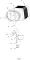
- Fig. 3 is a diagram of an isometric view of some of the inner parts of the ultrasound apparatus, according to an embodiment of the invention.
- the transducer cable 80 may run through a stabilizer 50 and may further run through the hollow shaft 62, to which the transducer is attached.
- the stabilizer 50 may be inserted into the first linear bearing 90 which may be able to turn around its axis 91 within the apparatus covering.
- the first linear bearing 90 may act as a guide for the stabilizer 50, as well as serving a purpose of the first stage rectifier of the cable distortion. As shown in the Fig.
- tan(d) Movement Radius of the shaft 62 (MR) / Length between the axis of the actuator and the axis 91 of the first linear bearing (LF).
- the cable 80 may be freely folded in a 180 degrees arc, with a desired radius up to a fixing point within the apparatus embodiment, as depicted in Fig. 2 .
- the arc may keep its radius, while its center displacement may be equal to the half of the cable Y direction motion amplitude.
- the apparatus 100 may have a control unit capable of receiving instructions such as by user interface 20.
- the user interface 20 may have buttons, levers, screen, touch screen or any other user interface components.
- the control unit which may also be logically connected to the electric actuator, may be capable of controlling the rotation of the ultrasound transducer, by controlling the electric actuator, for performing the received instructions from the user.
- the control unit may also be capable of controlling speed and angular amplitude of the transducer 40 in different manners for creating different massaging motion types.
- the control unit may control the transducer to move in a circular pattern without overlapping the ultrasound beam focus zone, thus increasing the equality of the energy applied to the whole treated area.
- the ultrasound apparatus may also comprise an electronic circuitry to allow user to control the motion's speed, the amplitude and/or the pattern of the ultrasound waves of the transducer.
- the actuator may be driven directly by applying electricity to the electric actuator.
- the described ultrasound apparatus may help to reduce the hardship of the manual motion during the treatment process used today. As described above, the use of the ultrasound apparatus may provide a more equal energy dispersion to the whole treated area in comparison to the manual moved transducer used today.
- the ultrasound apparatus may be used to increase the blood flow in the treated area due to ability to perform motions at the speed amplitude and pattern.
- the ultrasound apparatus may whirl the ultrasound transducer in certain types of motions, such as vibration or other, and it may generate its own low frequency waves which in coherence with the main ultrasound carrier frequency may produce more effective and more penetrative pulses not producible by a single frequency source.
- the ultrasound apparatus may have a coupler or a coupler mechanism such as gearbox, lever, camshaft or any other mechanism used for changing speed, pattern, torque or amplitude of motion of the ultrasound transducer whirled by the actuator.
- the ultrasound transducer may be directly attached to the electric actuator.
- the electric actuator, of the ultrasound apparatus may be driven by an electronic circuitry or by directly applied power, for whirling the ultrasound transducer in at least one motion type such as circular motion, linear motion, angular motion, spin motion, vibration, or other motion type, in at least one direction or combination of different directions and motion types.
- a motion type such as circular motion, linear motion, angular motion, spin motion, vibration, or other motion type, in at least one direction or combination of different directions and motion types.
Landscapes
- Health & Medical Sciences (AREA)
- Animal Behavior & Ethology (AREA)
- Biomedical Technology (AREA)
- Nuclear Medicine, Radiotherapy & Molecular Imaging (AREA)
- Radiology & Medical Imaging (AREA)
- Life Sciences & Earth Sciences (AREA)
- Engineering & Computer Science (AREA)
- General Health & Medical Sciences (AREA)
- Public Health (AREA)
- Veterinary Medicine (AREA)
- Ultra Sonic Daignosis Equipment (AREA)
- Surgical Instruments (AREA)
- Apparatuses For Generation Of Mechanical Vibrations (AREA)
- Percussion Or Vibration Massage (AREA)
Claims (12)
- Ein Ultraschallgerät (100) zum effizienten Auftragen von Ultraschallwellen auf ein behandeltes Gebiet durch mechanische Bewegung des Ultraschallwandlers, umfassend:einen Ultraschallwandler (40), der durch Verkabelung verbunden ist, um Ultraschallwellen zu verteilen;eine Welle (62) zum Halten des Wandlers;einen elektrischen Aktuator (10) zum Drehen einer Kurbel (60), wobei die Welle exzentrisch an der Kurbel befestigt ist, um den Wandler kreisförmig zu wirbeln;einen Stabilisator (50), um die Verkabelung des Ultraschallwandlers zu führen und die Welle zu halten;ein erstes Linearlager (90) zum Führen eines Teils des Stabilisators, während dieser Teil des Stabilisators in dem ersten Linearlager gleitet, wobei der Stabilisator die Welle in der Position normal zu dem ersten Linearlager hält, um das Verdrehen der Verkabelung des Ultraschallwandlers (40) zu reduzieren, wenn der Aktuator (10) den Wandler wirbelt; undeine Steuereinheit, die logisch mit dem elektrischen Aktuator verbunden ist, in der Lage ist, Anweisungen vom Benutzer zu empfangen und in der Lage ist, das Wirbeln des Ultraschallwandlers durch Steuerung des elektrischen Aktuators zur Ausführung der Anweisungen zu steuern.
- Ein Gerät nach Anspruch 1, weiter umfassend einen Reibungsminderer (70) und ein zweites Linearlager (73) zum Schutz der Verkabelung und zum Führen durch einen Rektifizierungsmechanismus, wenn der Aktuator den Wandler wirbelt.
- Ein Gerät nach Anspruch 1, wobei ein einziges Kabel eine kontinuierliche elektrische Verbindung vom Eingangsstecker des Geräts zum beweglichen Ultraschallwandler (40) bereitstellt, um eine Anzahl von Umdrehungen zu ermöglichen, ohne das Kabel zu beschädigen.
- Ein Gerät nach Anspruch 1, wobei der elektrische Aktuator (10) durch eine elektronische Schaltung oder durch direkt angelegte Leistung angetrieben wird, um den Ultraschallwandler (40) in mindestens einer Bewegungsart wie Kreisbewegung, Linearbewegung, Winkelbewegung, Drehbewegung, Vibration, in mindestens eine Richtung oder Kombination der genannten Richtungen und Bewegungsarten zu wirbeln.
- Ein Gerät nach Anspruch 1, weiter umfassend einen Stecker (200) mit mindestens einem BNC-Stecker zum Anschluss an das Ultraschallgerät, wobei die gesamte Steckermontage, einschließlich nicht-BNC-Kontakten, durch Nutzung des BNC-Verriegelungsmechanismus an Ort und Stelle gehalten wird.
- Ein Gerät nach Anspruch 1, wobei das Gerät als eigenständiges Gerät ausgeführt oder in eine größere, umfassendere Maschine integriert werden kann.
- Ein Gerät nach Anspruch 1, weiter umfassend eine Kupplung zur Änderung der Geschwindigkeit, des Musters, des Drehmoments oder der Amplitude der Bewegung des Ultraschallwandlers.
- Ein Gerät nach Anspruch 1, wobei der Ultraschallwandler direkt an den elektrischen Aktuator angeschlossen ist.
- Ein Gerät nach Anspruch 1, wobei das Gerät verwendet wird, um Verbrennungen zu vermeiden, die durch die Anwendung von Hochleistungsultraschall für eine längere als notwendige Zeit auf denselben Punkt des behandelten Gebiets verursacht werden.
- Ein Gerät nach Anspruch 1, wobei der elektrisch betriebene Ultraschallwandler verwendet wird, um den Blutfluss im behandelten Gebiet zu erhöhen, da er Bewegungen mit einer Geschwindigkeit, Amplitude und einem Muster ausführen kann, die manuell nicht möglich sind.
- Ein Gerät nach Anspruch 1, wobei der elektrisch betriebene Ultraschallwandler in bestimmten Bewegungsarten bewegt wird, die ihre eigenen Niederfrequenzwellen erzeugen, die in Kohärenz mit der Hauptultraschallträgerfrequenz effektivere und durchdringendere Impulse erzeugen, die von einer einzelnen Frequenzquelle nicht erzeugt werden können.
- Ein Gerät nach Anspruch 1, wobei der elektrisch betriebene Ultraschallwandler die Härte der manuellen Bewegung während des Behandlungsprozesses reduziert.
Applications Claiming Priority (2)
| Application Number | Priority Date | Filing Date | Title |
|---|---|---|---|
| US201862631649P | 2018-02-17 | 2018-02-17 | |
| PCT/IL2019/050185 WO2019159175A1 (en) | 2018-02-17 | 2019-02-15 | Ultrasound apparatus for mechanically applying ultrasound waves efficiently |
Publications (4)
| Publication Number | Publication Date |
|---|---|
| EP3752069A1 EP3752069A1 (de) | 2020-12-23 |
| EP3752069A4 EP3752069A4 (de) | 2021-11-17 |
| EP3752069C0 EP3752069C0 (de) | 2025-04-09 |
| EP3752069B1 true EP3752069B1 (de) | 2025-04-09 |
Family
ID=67618542
Family Applications (1)
| Application Number | Title | Priority Date | Filing Date |
|---|---|---|---|
| EP19754488.5A Active EP3752069B1 (de) | 2018-02-17 | 2019-02-15 | Ultraschallgerät zur effizienten mechanischen applikation von ultraschallwellen |
Country Status (10)
| Country | Link |
|---|---|
| US (1) | US11938347B2 (de) |
| EP (1) | EP3752069B1 (de) |
| JP (1) | JP7220720B2 (de) |
| KR (1) | KR102709189B1 (de) |
| CN (1) | CN111712199A (de) |
| AU (1) | AU2019221378B2 (de) |
| CA (1) | CA3090861A1 (de) |
| IL (1) | IL276085B2 (de) |
| WO (1) | WO2019159175A1 (de) |
| ZA (1) | ZA202004457B (de) |
Families Citing this family (4)
| Publication number | Priority date | Publication date | Assignee | Title |
|---|---|---|---|---|
| CN114306963B (zh) * | 2021-12-22 | 2025-11-07 | 上海茜茜纤美实业有限公司 | 一种旋转聚焦超声手具、负压手具及冷冻射频手具 |
| CN117258165A (zh) * | 2022-07-08 | 2023-12-22 | 付荣 | 一种便于操作的智能超声治疗系统及其使用方法 |
| CN115154253B (zh) * | 2022-09-08 | 2022-11-08 | 苏州好博医疗器械股份有限公司 | 一种具有自主移动功能的超声波治疗头 |
| WO2025169196A1 (en) * | 2024-02-08 | 2025-08-14 | Sonnext Ltd. | A handheld apparatus with a media dispenser and a method thereof |
Family Cites Families (15)
| Publication number | Priority date | Publication date | Assignee | Title |
|---|---|---|---|---|
| US4517985A (en) * | 1982-06-01 | 1985-05-21 | Diasonics, Inc. | Neonate ultrasonic scanner |
| DE3227624A1 (de) | 1982-07-23 | 1984-01-26 | Siemens AG, 1000 Berlin und 8000 München | Vorrichtung zur untersuchung der weiblichen brust mit ultraschall |
| US5520612A (en) | 1994-12-30 | 1996-05-28 | Exogen, Inc. | Acoustic system for bone-fracture therapy |
| US6425870B1 (en) | 2000-07-11 | 2002-07-30 | Vermon | Method and apparatus for a motorized multi-plane transducer tip |
| KR20030080507A (ko) * | 2002-04-09 | 2003-10-17 | 학교법인 경희대학교 | 초음파 혼의 편심 이동에 의한 자동 마사지 물리치료 장치 |
| US7883468B2 (en) * | 2004-05-18 | 2011-02-08 | Ethicon Endo-Surgery, Inc. | Medical system having an ultrasound source and an acoustic coupling medium |
| US8535228B2 (en) | 2004-10-06 | 2013-09-17 | Guided Therapy Systems, Llc | Method and system for noninvasive face lifts and deep tissue tightening |
| KR20240113495A (ko) | 2004-10-06 | 2024-07-22 | 가이디드 테라피 시스템스, 엘.엘.씨. | 초음파 치료 시스템 |
| KR100949067B1 (ko) | 2006-12-27 | 2010-03-25 | 주식회사 메디슨 | 초음파 진단장치의 프로브의 초음파 진동자 회동장치 |
| PT3058875T (pt) | 2008-06-06 | 2022-09-20 | Ulthera Inc | Sistema para tratamento cosmético e imagiologia |
| US8334635B2 (en) * | 2009-06-24 | 2012-12-18 | Ethicon Endo-Surgery, Inc. | Transducer arrangements for ultrasonic surgical instruments |
| JP5775929B2 (ja) | 2010-05-27 | 2015-09-09 | コーニンクレッカ フィリップス エヌ ヴェ | 超音波及び熱を選択的に生成する超音波トランスデューサ |
| CN103892871B (zh) | 2014-04-17 | 2015-11-25 | 深圳大学 | 一种机械旋转式血管内超声探头 |
| CN204274501U (zh) * | 2014-11-25 | 2015-04-22 | 重庆融海超声医学工程研究中心有限公司 | 机械手以及超声治疗系统 |
| KR101824462B1 (ko) | 2016-12-29 | 2018-02-01 | (주)클래시스 | 초음파 카트리지와 이를 이용한 초음파 치료용 헤드 |
-
2019
- 2019-02-15 EP EP19754488.5A patent/EP3752069B1/de active Active
- 2019-02-15 WO PCT/IL2019/050185 patent/WO2019159175A1/en not_active Ceased
- 2019-02-15 AU AU2019221378A patent/AU2019221378B2/en active Active
- 2019-02-15 CN CN201980012838.3A patent/CN111712199A/zh active Pending
- 2019-02-15 KR KR1020207026528A patent/KR102709189B1/ko active Active
- 2019-02-15 US US16/970,297 patent/US11938347B2/en active Active
- 2019-02-15 IL IL276085A patent/IL276085B2/en unknown
- 2019-02-15 JP JP2020543787A patent/JP7220720B2/ja active Active
- 2019-02-15 CA CA3090861A patent/CA3090861A1/en active Pending
-
2020
- 2020-07-20 ZA ZA2020/04457A patent/ZA202004457B/en unknown
Also Published As
| Publication number | Publication date |
|---|---|
| KR20200122339A (ko) | 2020-10-27 |
| US11938347B2 (en) | 2024-03-26 |
| NZ766429A (en) | 2024-07-26 |
| RU2020126261A3 (de) | 2022-02-07 |
| EP3752069A4 (de) | 2021-11-17 |
| EP3752069C0 (de) | 2025-04-09 |
| IL276085A (en) | 2020-08-31 |
| JP7220720B2 (ja) | 2023-02-10 |
| AU2019221378A1 (en) | 2020-08-13 |
| ZA202004457B (en) | 2022-12-21 |
| CN111712199A (zh) | 2020-09-25 |
| JP2021514703A (ja) | 2021-06-17 |
| US20230096237A1 (en) | 2023-03-30 |
| AU2019221378B2 (en) | 2024-10-31 |
| CA3090861A1 (en) | 2019-08-22 |
| EP3752069A1 (de) | 2020-12-23 |
| IL276085B2 (en) | 2024-11-01 |
| WO2019159175A1 (en) | 2019-08-22 |
| KR102709189B1 (ko) | 2024-09-23 |
| IL276085B1 (en) | 2024-07-01 |
| RU2020126261A (ru) | 2022-02-07 |
Similar Documents
| Publication | Publication Date | Title |
|---|---|---|
| EP3752069B1 (de) | Ultraschallgerät zur effizienten mechanischen applikation von ultraschallwellen | |
| CN113797455B (zh) | 可调节超声波聚焦深度的超声波产生装置及其控制方法 | |
| KR101824465B1 (ko) | 초음파 치료용 헤드 | |
| US20110237930A1 (en) | MRI compatible motor and positioning system | |
| KR20100120188A (ko) | 초음파 시스템을 이용한 치료 헤드 | |
| KR101824463B1 (ko) | 초음파 치료용 헤드 | |
| KR102828835B1 (ko) | 초음파 집속점 이동 카트리지 및 이를 포함하는 초음파 시술장치 | |
| KR101782523B1 (ko) | 초음파 트랜스듀서 운동장치 및 이를 이용한 초음파 치료용 헤드 | |
| CN206315368U (zh) | 一种治疗床移载装置 | |
| KR20230082287A (ko) | 구동부를 포함하는 초음파시술장치 | |
| RU2778731C2 (ru) | Ультразвуковой аппарат для эффективного механического воздействия с помощью ультразвуковых волн | |
| KR101775694B1 (ko) | 초음파 트랜스듀서 운동장치 및 이를 이용한 초음파 치료용 헤드 | |
| KR102117636B1 (ko) | 초음파 치료 카트리지 및 이를 포함하는 치료 장치 | |
| KR101902895B1 (ko) | 초음파 트랜스듀서 작동용 피봇 운동 구조체 | |
| KR101874532B1 (ko) | 초음파 치료용 헤드 | |
| CN107617168A (zh) | 一种治疗床移载装置 | |
| KR20260033216A (ko) | 고강도 집속 초음파 장치 | |
| WO2025064164A1 (en) | Ultrasound needle guidance systems and methods including pain reduction vibration | |
| KR20170099585A (ko) | 시술용 의료장비의 거치장치 |
Legal Events
| Date | Code | Title | Description |
|---|---|---|---|
| STAA | Information on the status of an ep patent application or granted ep patent |
Free format text: STATUS: THE INTERNATIONAL PUBLICATION HAS BEEN MADE |
|
| PUAI | Public reference made under article 153(3) epc to a published international application that has entered the european phase |
Free format text: ORIGINAL CODE: 0009012 |
|
| STAA | Information on the status of an ep patent application or granted ep patent |
Free format text: STATUS: REQUEST FOR EXAMINATION WAS MADE |
|
| 17P | Request for examination filed |
Effective date: 20200720 |
|
| AK | Designated contracting states |
Kind code of ref document: A1 Designated state(s): AL AT BE BG CH CY CZ DE DK EE ES FI FR GB GR HR HU IE IS IT LI LT LU LV MC MK MT NL NO PL PT RO RS SE SI SK SM TR |
|
| AX | Request for extension of the european patent |
Extension state: BA ME |
|
| DAV | Request for validation of the european patent (deleted) | ||
| DAX | Request for extension of the european patent (deleted) | ||
| REG | Reference to a national code |
Ref country code: DE Ref legal event code: R079 Ipc: A61N0007000000 Ref country code: DE Ref legal event code: R079 Ref document number: 602019068422 Country of ref document: DE Free format text: PREVIOUS MAIN CLASS: A61B0008000000 Ipc: A61N0007000000 |
|
| A4 | Supplementary search report drawn up and despatched |
Effective date: 20211014 |
|
| RIC1 | Information provided on ipc code assigned before grant |
Ipc: A61N 7/00 20060101AFI20211008BHEP |
|
| GRAP | Despatch of communication of intention to grant a patent |
Free format text: ORIGINAL CODE: EPIDOSNIGR1 |
|
| STAA | Information on the status of an ep patent application or granted ep patent |
Free format text: STATUS: GRANT OF PATENT IS INTENDED |
|
| INTG | Intention to grant announced |
Effective date: 20241030 |
|
| GRAS | Grant fee paid |
Free format text: ORIGINAL CODE: EPIDOSNIGR3 |
|
| GRAA | (expected) grant |
Free format text: ORIGINAL CODE: 0009210 |
|
| STAA | Information on the status of an ep patent application or granted ep patent |
Free format text: STATUS: THE PATENT HAS BEEN GRANTED |
|
| AK | Designated contracting states |
Kind code of ref document: B1 Designated state(s): AL AT BE BG CH CY CZ DE DK EE ES FI FR GB GR HR HU IE IS IT LI LT LU LV MC MK MT NL NO PL PT RO RS SE SI SK SM TR |
|
| REG | Reference to a national code |
Ref country code: GB Ref legal event code: FG4D |
|
| REG | Reference to a national code |
Ref country code: CH Ref legal event code: EP |
|
| REG | Reference to a national code |
Ref country code: DE Ref legal event code: R096 Ref document number: 602019068422 Country of ref document: DE |
|
| REG | Reference to a national code |
Ref country code: IE Ref legal event code: FG4D |
|
| U01 | Request for unitary effect filed |
Effective date: 20250409 |
|
| U07 | Unitary effect registered |
Designated state(s): AT BE BG DE DK EE FI FR IT LT LU LV MT NL PT RO SE SI Effective date: 20250417 |
|
| PG25 | Lapsed in a contracting state [announced via postgrant information from national office to epo] |
Ref country code: ES Free format text: LAPSE BECAUSE OF FAILURE TO SUBMIT A TRANSLATION OF THE DESCRIPTION OR TO PAY THE FEE WITHIN THE PRESCRIBED TIME-LIMIT Effective date: 20250409 |
|
| PG25 | Lapsed in a contracting state [announced via postgrant information from national office to epo] |
Ref country code: NO Free format text: LAPSE BECAUSE OF FAILURE TO SUBMIT A TRANSLATION OF THE DESCRIPTION OR TO PAY THE FEE WITHIN THE PRESCRIBED TIME-LIMIT Effective date: 20250709 Ref country code: GR Free format text: LAPSE BECAUSE OF FAILURE TO SUBMIT A TRANSLATION OF THE DESCRIPTION OR TO PAY THE FEE WITHIN THE PRESCRIBED TIME-LIMIT Effective date: 20250710 |
|
| PG25 | Lapsed in a contracting state [announced via postgrant information from national office to epo] |
Ref country code: PL Free format text: LAPSE BECAUSE OF FAILURE TO SUBMIT A TRANSLATION OF THE DESCRIPTION OR TO PAY THE FEE WITHIN THE PRESCRIBED TIME-LIMIT Effective date: 20250409 |
|
| PG25 | Lapsed in a contracting state [announced via postgrant information from national office to epo] |
Ref country code: HR Free format text: LAPSE BECAUSE OF FAILURE TO SUBMIT A TRANSLATION OF THE DESCRIPTION OR TO PAY THE FEE WITHIN THE PRESCRIBED TIME-LIMIT Effective date: 20250409 |
|
| PG25 | Lapsed in a contracting state [announced via postgrant information from national office to epo] |
Ref country code: RS Free format text: LAPSE BECAUSE OF FAILURE TO SUBMIT A TRANSLATION OF THE DESCRIPTION OR TO PAY THE FEE WITHIN THE PRESCRIBED TIME-LIMIT Effective date: 20250709 |
|
| PG25 | Lapsed in a contracting state [announced via postgrant information from national office to epo] |
Ref country code: IS Free format text: LAPSE BECAUSE OF FAILURE TO SUBMIT A TRANSLATION OF THE DESCRIPTION OR TO PAY THE FEE WITHIN THE PRESCRIBED TIME-LIMIT Effective date: 20250809 |
|
| PG25 | Lapsed in a contracting state [announced via postgrant information from national office to epo] |
Ref country code: SM Free format text: LAPSE BECAUSE OF FAILURE TO SUBMIT A TRANSLATION OF THE DESCRIPTION OR TO PAY THE FEE WITHIN THE PRESCRIBED TIME-LIMIT Effective date: 20250409 |
|
| PG25 | Lapsed in a contracting state [announced via postgrant information from national office to epo] |
Ref country code: CZ Free format text: LAPSE BECAUSE OF FAILURE TO SUBMIT A TRANSLATION OF THE DESCRIPTION OR TO PAY THE FEE WITHIN THE PRESCRIBED TIME-LIMIT Effective date: 20250409 |
|
| PG25 | Lapsed in a contracting state [announced via postgrant information from national office to epo] |
Ref country code: SK Free format text: LAPSE BECAUSE OF FAILURE TO SUBMIT A TRANSLATION OF THE DESCRIPTION OR TO PAY THE FEE WITHIN THE PRESCRIBED TIME-LIMIT Effective date: 20250409 |
|
| PLBE | No opposition filed within time limit |
Free format text: ORIGINAL CODE: 0009261 |
|
| STAA | Information on the status of an ep patent application or granted ep patent |
Free format text: STATUS: NO OPPOSITION FILED WITHIN TIME LIMIT |
|
| REG | Reference to a national code |
Ref country code: CH Ref legal event code: L10 Free format text: ST27 STATUS EVENT CODE: U-0-0-L10-L00 (AS PROVIDED BY THE NATIONAL OFFICE) Effective date: 20260218 |
|
| 26N | No opposition filed |
Effective date: 20260112 |