EP3751908A1 - Handhabung von non-access-stratum-verbindung in ntn - Google Patents
Handhabung von non-access-stratum-verbindung in ntn Download PDFInfo
- Publication number
- EP3751908A1 EP3751908A1 EP20179830.3A EP20179830A EP3751908A1 EP 3751908 A1 EP3751908 A1 EP 3751908A1 EP 20179830 A EP20179830 A EP 20179830A EP 3751908 A1 EP3751908 A1 EP 3751908A1
- Authority
- EP
- European Patent Office
- Prior art keywords
- nas
- amf
- network
- access network
- access
- Prior art date
- Legal status (The legal status is an assumption and is not a legal conclusion. Google has not performed a legal analysis and makes no representation as to the accuracy of the status listed.)
- Granted
Links
Images


Classifications
-
- H—ELECTRICITY
- H04—ELECTRIC COMMUNICATION TECHNIQUE
- H04B—TRANSMISSION
- H04B7/00—Radio transmission systems, i.e. using radiation field
- H04B7/14—Relay systems
- H04B7/15—Active relay systems
- H04B7/185—Space-based or airborne stations; Stations for satellite systems
- H04B7/18523—Satellite systems for providing broadcast service to terrestrial stations, i.e. broadcast satellite service
- H04B7/18526—Arrangements for data linking, networking or transporting, or for controlling an end to end session
-
- H—ELECTRICITY
- H04—ELECTRIC COMMUNICATION TECHNIQUE
- H04W—WIRELESS COMMUNICATION NETWORKS
- H04W48/00—Access restriction; Network selection; Access point selection
-
- H—ELECTRICITY
- H04—ELECTRIC COMMUNICATION TECHNIQUE
- H04B—TRANSMISSION
- H04B7/00—Radio transmission systems, i.e. using radiation field
- H04B7/14—Relay systems
- H04B7/15—Active relay systems
- H04B7/185—Space-based or airborne stations; Stations for satellite systems
-
- H—ELECTRICITY
- H04—ELECTRIC COMMUNICATION TECHNIQUE
- H04B—TRANSMISSION
- H04B7/00—Radio transmission systems, i.e. using radiation field
- H04B7/14—Relay systems
- H04B7/15—Active relay systems
- H04B7/185—Space-based or airborne stations; Stations for satellite systems
- H04B7/1853—Satellite systems for providing telephony service to a mobile station, i.e. mobile satellite service
- H04B7/18539—Arrangements for managing radio, resources, i.e. for establishing or releasing a connection
-
- H—ELECTRICITY
- H04—ELECTRIC COMMUNICATION TECHNIQUE
- H04B—TRANSMISSION
- H04B7/00—Radio transmission systems, i.e. using radiation field
- H04B7/14—Relay systems
- H04B7/15—Active relay systems
- H04B7/185—Space-based or airborne stations; Stations for satellite systems
- H04B7/19—Earth-synchronous stations
-
- H—ELECTRICITY
- H04—ELECTRIC COMMUNICATION TECHNIQUE
- H04B—TRANSMISSION
- H04B7/00—Radio transmission systems, i.e. using radiation field
- H04B7/14—Relay systems
- H04B7/15—Active relay systems
- H04B7/185—Space-based or airborne stations; Stations for satellite systems
- H04B7/195—Non-synchronous stations
-
- H—ELECTRICITY
- H04—ELECTRIC COMMUNICATION TECHNIQUE
- H04W—WIRELESS COMMUNICATION NETWORKS
- H04W24/00—Supervisory, monitoring or testing arrangements
- H04W24/02—Arrangements for optimising operational condition
-
- H—ELECTRICITY
- H04—ELECTRIC COMMUNICATION TECHNIQUE
- H04W—WIRELESS COMMUNICATION NETWORKS
- H04W48/00—Access restriction; Network selection; Access point selection
- H04W48/16—Discovering, processing access restriction or access information
-
- H—ELECTRICITY
- H04—ELECTRIC COMMUNICATION TECHNIQUE
- H04W—WIRELESS COMMUNICATION NETWORKS
- H04W76/00—Connection management
- H04W76/20—Manipulation of established connections
- H04W76/25—Maintenance of established connections
-
- H—ELECTRICITY
- H04—ELECTRIC COMMUNICATION TECHNIQUE
- H04W—WIRELESS COMMUNICATION NETWORKS
- H04W8/00—Network data management
- H04W8/02—Processing of mobility data, e.g. registration information at HLR [Home Location Register] or VLR [Visitor Location Register]; Transfer of mobility data, e.g. between HLR, VLR or external networks
- H04W8/08—Mobility data transfer
-
- H—ELECTRICITY
- H04—ELECTRIC COMMUNICATION TECHNIQUE
- H04W—WIRELESS COMMUNICATION NETWORKS
- H04W88/00—Devices specially adapted for wireless communication networks, e.g. terminals, base stations or access point devices
- H04W88/14—Backbone network devices
-
- H—ELECTRICITY
- H04—ELECTRIC COMMUNICATION TECHNIQUE
- H04W—WIRELESS COMMUNICATION NETWORKS
- H04W60/00—Affiliation to network, e.g. registration; Terminating affiliation with the network, e.g. de-registration
-
- H—ELECTRICITY
- H04—ELECTRIC COMMUNICATION TECHNIQUE
- H04W—WIRELESS COMMUNICATION NETWORKS
- H04W76/00—Connection management
- H04W76/10—Connection setup
-
- H—ELECTRICITY
- H04—ELECTRIC COMMUNICATION TECHNIQUE
- H04W—WIRELESS COMMUNICATION NETWORKS
- H04W84/00—Network topologies
- H04W84/02—Hierarchically pre-organised networks, e.g. paging networks, cellular networks, WLAN [Wireless Local Area Network] or WLL [Wireless Local Loop]
- H04W84/04—Large scale networks; Deep hierarchical networks
- H04W84/042—Public Land Mobile systems, e.g. cellular systems
-
- H—ELECTRICITY
- H04—ELECTRIC COMMUNICATION TECHNIQUE
- H04W—WIRELESS COMMUNICATION NETWORKS
- H04W84/00—Network topologies
- H04W84/02—Hierarchically pre-organised networks, e.g. paging networks, cellular networks, WLAN [Wireless Local Area Network] or WLL [Wireless Local Loop]
- H04W84/04—Large scale networks; Deep hierarchical networks
- H04W84/06—Airborne or Satellite Networks
Definitions
- a wireless device receives, from a base station, access network information indicating an access network type of a plurality of access network types comprising: a geostationary earth orbit (GEO) access network type; and a low earth orbit (LEO) access network type.
- access network information indicating an access network type of a plurality of access network types comprising: a geostationary earth orbit (GEO) access network type; and a low earth orbit (LEO) access network type.
- GEO geostationary earth orbit
- LEO low earth orbit
- a wireless device sends to an access and mobility management function (AMF) via a base station, a first non-access stratum (NAS) request message.
- the base station may be connected to the AMF via a backhaul interface.
- the wireless device may receive from the AMF, an NAS response message.
- the NAS response message may comprise information of the backhaul interface.
- Example embodiments of the present invention enable implementation of enhanced features and functionalities in 4G/5G systems.
- Embodiments of the technology disclosed herein may be employed in the technical field of 4G/5G systems and network slicing for communication systems. More particularly, the embodiments of the technology disclosed herein may relate to 5G core network and 5G systems for network slicing in communication systems.
- UE, wireless device, and mobile device are used interchangeably.
- Example FIG. 1 and FIG. 2 depict a 5G system comprising of access networks and 5G core network.
- An example 5G access network may comprise an access network connecting to a 5G core network.
- An access network may comprise an NG-RAN 105 and/or non-3GPP AN 165.
- An example 5G core network may connect to one or more 5G access networks 5G-AN and/or NG-RANs.
- 5G core network may comprise functional elements or network functions as in example FIG. 1 and example FIG. 2 where interfaces may be employed for communication among the functional elements and/or network elements.
- a network function may be a processing function in a network, which may have a functional behavior and/or interfaces.
- a network function may be implemented either as a network element on a dedicated hardware, and/or a network node as depicted in FIG. 3 and FIG. 4 , or as a software instance running on a dedicated hardware and/or shared hardware, or as a virtualized function instantiated on an appropriate platform.
- access and mobility management function may include the following functionalities (some of the AMF 155 functionalities may be supported in a single instance of an AMF 155): termination of RAN 105 CP interface (N2), termination of NAS (N1), NAS ciphering and integrity protection, registration management, connection management, reachability management, mobility management, lawful intercept (for AMF 155 events and interface to LI system), provide transport for session management, SM messages between UE 100 and SMF 160, transparent proxy for routing SM messages, access authentication, access authorization, provide transport for SMS messages between UE 100 and SMSF, security anchor function, SEA, interaction with the AUSF 150 and the UE 100, receiving the intermediate key established as a result of the UE 100 authentication process, security context management, SCM, that receives a key from the SEA that it uses to derive access network specific keys, and/or the like.
- the AMF 155 may support non-3GPP access networks through N2 interface with N3IWF 170, NAS signaling with a UE 100 over N3IWF 170, authentication of UEs connected over N3IWF 170, management of mobility, authentication, and separate security context state(s) of a UE 100 connected via non-3GPP access 165 or connected via 3GPP access 105 and non-3GPP access 165 simultaneously, support of a coordinated RM context valid over 3GPP access 105 and non 3GPP access 165, support of CM management contexts for the UE 100 for connectivity over non-3GPP access, and/or the like.
- an AMF 155 region may comprise one or multiple AMF 155 sets.
- the AMF 155 set may comprise some AMF 155 that serve a given area and/or network slice(s). In an example, multiple AMF 155 sets may be per AMF 155 region and/or network slice(s).
- Application identifier may be an identifier that may be mapped to a specific application traffic detection rule.
- Configured NSSAI may be an NSSAI that may be provisioned in a UE 100.
- DN 115 access identifier (DNAI), for a DNN may be an identifier of a user plane access to a DN 115.
- Initial registration may be related to a UE 100 registration in RM-DEREGISTERED 500, 520 states.
- N2AP UE 100 association may be a logical per UE 100 association between a 5G AN node and an AMF 155.
- N2AP UE-TNLA-binding may be a binding between a N2AP UE 100 association and a specific transport network layer, TNL association for a given UE 100.
- session management function may include one or more of the following functionalities (one or more of the SMF 160 functionalities may be supported in a single instance of a SMF 160): session management (e.g. session establishment, modify and release, including tunnel maintain between UPF 110 and AN 105 node), UE 100 IP address allocation & management (including optional authorization), selection and control of UP function(s), configuration of traffic steering at UPF 110 to route traffic to proper destination, termination of interfaces towards policy control functions, control part of policy enforcement and QoS.
- session management e.g. session establishment, modify and release, including tunnel maintain between UPF 110 and AN 105 node
- UE 100 IP address allocation & management including optional authorization
- selection and control of UP function(s) configuration of traffic steering at UPF 110 to route traffic to proper destination, termination of interfaces towards policy control functions, control part of policy enforcement and QoS.
- lawful intercept for SM events and interface to LI System
- termination of SM parts of NAS messages downlink data notification
- initiation of AN specific SM information sent via AMF 155 over N2 to (R)AN 105
- determination of SSC mode of a session roaming functionality, handling local enforcement to apply QoS SLAs (VPLMN), charging data collection and charging interface (VPLMN), lawful intercept (in VPLMN for SM events and interface to LI System), support for interaction with external DN 115 for transport of signaling for PDU session authorization/authentication by external DN 115, and/or the like.
- QoS SLAs QoS SLAs
- VPLMN charging data collection and charging interface
- lawful intercept in VPLMN for SM events and interface to LI System
- support for interaction with external DN 115 for transport of signaling for PDU session authorization/authentication by external DN 115, and/or the like.
- a user plane function may include one or more of the following functionalities (some of the UPF 110 functionalities may be supported in a single instance of a UPF 110): anchor point for Intra-/Inter-RAT mobility (when applicable), external PDU session point of interconnect to DN 115, packet routing & forwarding, packet inspection and user plane part of policy rule enforcement, lawful intercept (UP collection), traffic usage reporting, uplink classifier to support routing traffic flows to a data network, branching point to support multi-homed PDU session(s), QoS handling for user plane, uplink traffic verification (SDF to QoS flow mapping), transport level packet marking in the uplink and downlink, downlink packet buffering, downlink data notification triggering, and/or the like.
- anchor point for Intra-/Inter-RAT mobility when applicable
- external PDU session point of interconnect to DN 115 packet routing & forwarding
- packet inspection and user plane part of policy rule enforcement lawful intercept (UP collection)
- UP collection lawful intercept
- traffic usage reporting uplink classifier to
- the UE 100 IP address management may include allocation and release of the UE 100 IP address and/or renewal of the allocated IP address.
- the UE 100 may set a requested PDU type during a PDU session establishment procedure based on its IP stack capabilities and/or configuration.
- the SMF 160 may select PDU type of a PDU session.
- the SMF 160 may select PDU type IPv4 or IPv6 based on DNN configuration and/or operator policies.
- the SMF 160 may provide a cause value to the UE 100 to indicate whether the other IP version is supported on the DNN.
- the SMF 160 may select the requested PDU type.
- the 5GC elements and UE 100 may support the following mechanisms: during a PDU session establishment procedure, the SMF 160 may send the IP address to the UE 100 via SM NAS signaling.
- the IPv4 address allocation and/or IPv4 parameter configuration via DHCPv4 may be employed once PDU session may be established.
- IPv6 prefix allocation may be supported via IPv6 stateless autoconfiguration, if IPv6 is supported.
- 5GC network elements may support IPv6 parameter configuration via stateless DHCPv6.
- the 5GC may support the allocation of a static IPv4 address and/or a static IPv6 prefix based on subscription information in a UDM 140 and/or based on the configuration on a per-subscriber, per-DNN basis.
- User plane function(s) may handle the user plane path of PDU sessions.
- a UPF 110 that provides the interface to a data network may support functionality of a PDU session anchor.
- a policy control function may support unified policy framework to govern network behavior, provide policy rules to control plane function(s) to enforce policy rules, implement a front end to access subscription information relevant for policy decisions in a user data repository (UDR), and/or the like.
- UDR user data repository
- a network exposure function, NEF 125 may provide means to securely expose the services and capabilities provided by the 3GPP network functions, translate between information exchanged with the AF 145 and information exchanged with the internal network functions, receive information from other network functions, and/or the like.
- NRF 130 may support service discovery function that may receive NF discovery request from NF instance, provide information about the discovered NF instances (be discovered) to the NF instance, and maintain information about available NF instances and their supported services, and/or the like.
- an NSSF 120 may select a set of network slice instances serving the UE 100, may determine allowed NSSAI. In an example, the NSSF 120 may determine the AMF 155 set to be employed to serve the UE 100, and/or, based on configuration, determine a list of candidate AMF 155(s) 155 by querying the NRF 130.
- stored data in a UDR may include at least user subscription data, including at least subscription identifiers, security credentials, access and mobility related subscription data, session related subscription data, policy data, and/or the like.
- an AUSF 150 may support authentication server function (AUSF 150).
- an application function may interact with the 3GPP core network to provide services.
- application functions may be trusted by the operator to interact directly with relevant network functions.
- Application functions not allowed by the operator to access directly the network functions may use an external exposure framework (e.g., via the NEF 125) to interact with relevant network functions.
- control plane interface between the (R)AN 105 and the 5G core may support connection of multiple different kinds of AN(s) (e.g. 3GPP RAN 105, N3IWF 170 for Un-trusted access 165) to the 5GC via a control plane protocol.
- AN(s) e.g. 3GPP RAN 105, N3IWF 170 for Un-trusted access 165
- an N2 AP protocol may be employed for both the 3GPP access 105 and non-3GPP access 165.
- control plane interface between the (R)AN 105 and the 5G core may support decoupling between AMF 155 and other functions such as SMF 160 that may need to control the services supported by AN(s) (e.g. control of the UP resources in the AN 105 for a PDU session).
- the 5GC may provide policy information from the PCF 135 to the UE 100.
- the policy information may comprise: access network discovery and selection policy, UE 100 route selection policy (URSP), SSC mode selection policy (SSCMSP), network slice selection policy (NSSP), DNN selection policy, non-seamless offload policy, and/or the like.
- the registration management, RM may be employed to register or de-register a UE/user 100 with the network and establish the user context in the network.
- Connection management may be employed to establish and release the signaling connection between the UE 100 and the AMF 155.
- a UE 100 may register with the network to receive services that require registration.
- the UE 100 may update its registration with the network periodically in order to remain reachable (periodic registration update), or upon mobility (e.g., mobility registration update), or to update its capabilities or to re-negotiate protocol parameters.
- an initial registration procedure as depicted in example FIG. 8 and FIG. 9 may involve execution of network access control functions (e.g. user authentication and access authorization based on subscription profiles in UDM 140).
- Example FIG. 9 is a continuation of the initial registration procedure depicted in FIG. 8 .
- the identity of the serving AMF 155 may be registered in a UDM 140.
- the registration management, RM procedures may be applicable over both 3GPP access 105 and non 3GPP access 165.
- FIG. 5A may depict the RM states of a UE 100 as observed by the UE 100 and AMF 155.
- two RM states may be employed in the UE 100 and the AMF 155 that may reflect the registration status of the UE 100 in the selected PLMN: RM-DEREGISTERED 500, and RM-REGISTERED 510.
- the UE 100 in the RM DEREGISTERED state 500, the UE 100 may not be registered with the network.
- the UE 100 context in the AMF 155 may not hold valid location or routing information for the UE 100 so the UE 100 may not be reachable by the AMF 155.
- the UE 100 context may be stored in the UE 100 and the AMF 155.
- the UE 100 in the RM REGISTERED state 510, the UE 100 may be registered with the network.
- the UE 100 may receive services that may require registration with the network.
- two RM states may be employed in AMF 155 for the UE 100 that may reflect the registration status of the UE 100 in the selected PLMN: RM-DEREGISTERED 520, and RM-REGISTERED 530.
- connection management may comprise establishing and releasing a signaling connection between a UE 100 and an AMF 155 over N1 interface.
- the signaling connection may be employed to enable NAS signaling exchange between the UE 100 and the core network.
- the signaling connection between the UE 100 and the AMF 155 may comprise both the AN signaling connection between the UE 100 and the (R)AN 105 (e.g. RRC connection over 3GPP access) and the N2 connection for the UE 100 between the AN and the AMF 155.
- two CM states may be employed for the NAS signaling connectivity of the UE 100 with the AMF 155, CM-IDLE 600, 620 and CM-CONNECTED 610, 630.
- a UE 100 in CM-IDLE 600 state may be in RM-REGISTERED 510 state and may have no NAS signaling connection established with the AMF 155 over N1.
- the UE 100 may perform cell selection, cell reselection, PLMN selection, and/or the like.
- a UE 100 in CM-CONNECTED 610 state may have a NAS signaling connection with the AMF 155 over N1.
- two CM states may be employed for the UE 100 at the AMF 155, CM-IDLE 620 and CM-CONNECTED 630.
- an RRC inactive state may apply to NG-RAN (e.g. it may apply to NR and E-UTRA connected to 5G CN).
- the AMF 155 may provide assistance information to the NG RAN 105, to assist the NG RAN's 105 decision whether the UE 100 may be sent to RRC inactive state.
- the UE 100 may resume the RRC connection due to uplink data pending, mobile initiated signaling procedure, as a response to RAN 105 paging, to notify the network that it has left the RAN 105 notification area, and/or the like.
- a NAS signaling connection management may include establishing and releasing a NAS signaling connection.
- a NAS signaling connection establishment function may be provided by the UE 100 and the AMF 155 to establish the NAS signaling connection for the UE 100 in CM-IDLE 600 state.
- the procedure of releasing the NAS signaling connection may be initiated by the 5G (R)AN 105 node or the AMF 155.
- reachability management of a UE 100 may detect whether the UE 100 is reachable and may provide the UE 100 location (e.g. access node) to the network to reach the UE 100. Reachability management may be done by paging the UE 100 and the UE 100 location tracking.
- the UE 100 location tracking may include both UE 100 registration area tracking and UE 100 reachability tracking.
- the UE 100 and the AMF 155 may negotiate UE 100 reachability characteristics in CM-IDLE 600, 620 state during registration and registration update procedures.
- two UE 100 reachability categories may be negotiated between a UE 100 and an AMF 155 for CM-IDLE 600, 620 state. 1) UE 100 reachability allowing mobile device terminated data while the UE 100 is CM-IDLE 600 mode. 2) Mobile initiated connection only (MICO) mode.
- the 5GC may support a PDU connectivity service that provides exchange of PDUs between the UE 100 and a data network identified by a DNN. The PDU connectivity service may be supported via PDU sessions that are established upon request from the UE 100.
- a PDU session may support one or more PDU session types.
- PDU sessions may be established (e.g. upon UE 100 request), modified (e.g. upon UE 100 and 5GC request) and/or released (e.g. upon UE 100 and 5GC request) using NAS SM signaling exchanged over N1 between the UE 100 and the SMF 160.
- the 5GC may be able to trigger a specific application in the UE 100.
- the UE 100 may send it to the identified application in the UE 100.
- the identified application in the UE 100 may establish a PDU session to a specific DNN.
- the 5G QoS model may support a QoS flow based framework as depicted in example FIG. 7 .
- the 5G QoS model may support both QoS flows that require a guaranteed flow bit rate and QoS flows that may not require a guaranteed flow bit rate.
- the 5G QoS model may support reflective QoS.
- the QoS model may comprise flow mapping or packet marking at the UPF 110 (CN_UP) 110, AN 105 and/or the UE 100. In an example, packets may arrive from and/or destined to the application/service layer 730 of UE 100, UPF 110 (CN_UP) 110, and/or the AF 145.
- the QoS flow may be a granularity of QoS differentiation in a PDU session.
- a QoS flow ID, QFI may be employed to identify the QoS flow in the 5G system.
- user plane traffic with the same QFI within a PDU session may receive the same traffic forwarding treatment.
- the QFI may be carried in an encapsulation header on N3 and/or N9 (e.g. without any changes to the end-to-end packet header).
- the QFI may be applied to PDUs with different types of payload.
- the QFI may be unique within a PDU session.
- the QoS parameters of a QoS flow may be provided to the (R)AN 105 as a QoS profile over N2 at PDU session establishment, QoS flow establishment, or when NG-RAN is used at every time the user plane is activated.
- a default QoS rule may be required for every PDU session.
- the SMF 160 may allocate the QFI for a QoS flow and may derive QoS parameters from the information provided by the PCF 135.
- the SMF 160 may provide the QFI together with the QoS profile containing the QoS parameters of a QoS flow to the (R)AN 105.
- 5G QoS flow may be a granularity for QoS forwarding treatment in the 5G system.
- Traffic mapped to the same 5G QoS flow may receive the same forwarding treatment (e.g. scheduling policy, queue management policy, rate shaping policy, RLC configuration, and/or the like).
- providing different QoS forwarding treatment may require separate 5G QoS flows.
- a 5G QoS indicator may be a scalar that may be employed as a reference to a specific QoS forwarding behavior (e.g. packet loss rate, packet delay budget) to be provided to a 5G QoS flow.
- the 5G QoS indicator may be implemented in the access network by the 5QI referencing node specific parameters that may control the QoS forwarding treatment (e.g. scheduling weights, admission thresholds, queue management thresholds, link layer protocol configuration, and/or the like.).
- 5GC may support edge computing and may enable operator(s) and 3rd party services to be hosted close to the UE's access point of attachment.
- the 5G core network may select a UPF 110 close to the UE 100 and may execute the traffic steering from the UPF 110 to the local data network via a N6 interface.
- the selection and traffic steering may be based on the UE's 100 subscription data, UE 100 location, the information from application function AF 145, policy, other related traffic rules, and/or the like.
- the 5G core network may expose network information and capabilities to an edge computing application function.
- the functionality support for edge computing may include local routing where the 5G core network may select a UPF 110 to route the user traffic to the local data network, traffic steering where the 5G core network may select the traffic to be routed to the applications in the local data network, session and service continuity to enable UE 100 and application mobility, user plane selection and reselection, e.g. based on input from application function, network capability exposure where 5G core network and application function may provide information to each other via NEf 125, QoS and charging where PCF 135 may provide rules for QoS control and charging for the traffic routed to the local data network, support of local area data network where 5G core network may provide support to connect to the LADN in a certain area where the applications are deployed, and/or the like.
- An example 5G system may be a 3GPP system comprising of 5G access network 105, 5G core network and a UE 100, and/or the like. Allowed NSSAI may be an NSSAI provided by a serving PLMN during e.g. a registration procedure, indicating the NSSAI allowed by the network for the UE 100 in the serving PLMN for the current registration area.
- a PDU connectivity service may provide exchange of PDUs between a UE 100 and a data network.
- a PDU session may be an association between the UE 100 and the data network, DN 115, that may provide the PDU connectivity service.
- the type of association may be IP, Ethernet and/or unstructured.
- Establishment of user plane connectivity to a data network via network slice instance(s) may comprise the following: performing a RM procedure to select an AMF 155 that supports the required network slices, and establishing one or more PDU session(s) to the required data network via the network slice instance(s).
- the set of network slices for a UE 100 may be changed at any time while the UE 100 may be registered with the network, and may be initiated by the network, or the UE 100.
- a periodic registration update may be UE 100 re-registration at expiry of a periodic registration timer.
- a requested NSSAI may be a NSSAI that the UE 100 may provide to the network.
- a service based interface may represent how a set of services may be provided/exposed by a given NF.
- a service continuity may be an uninterrupted user experience of a service, including the cases where the IP address and/or anchoring point may change.
- a session continuity may refer to continuity of a PDU session. For PDU session of IP type session continuity may imply that the IP address is preserved for the lifetime of the PDU session.
- An uplink classifier may be a UPF 110 functionality that aims at diverting uplink traffic, based on filter rules provided by the SMF 160, towards data network, DN 115.
- the 5G system architecture may support data connectivity and services enabling deployments to use techniques such as e.g. network function virtualization and/or software defined networking.
- the 5G system architecture may leverage service-based interactions between control plane (CP) network functions where identified.
- CP control plane
- UP user plane
- a 5G system may enable a network function to interact with other NF(s) directly if required.
- the 5G system may reduce dependencies between the access network (AN) and the core network (CN).
- the architecture may comprise a converged access-agnostic core network with a common AN - CN interface which may integrate different 3GPP and non-3GPP access types.
- the 5G system may support a unified authentication framework, stateless NFs, where the compute resource is decoupled from the storage resource, capability exposure, and concurrent access to local and centralized services.
- UP functions may be deployed close to the access network.
- the 5G system may support roaming with home routed traffic and/or local breakout traffic in the visited PLMN.
- An example 5G architecture may be service-based and the interaction between network functions may be represented in two ways. (1) As service-based representation (depicted in example FIG. 1 ), where network functions within the control plane, may enable other authorized network functions to access their services. This representation may also include point-to-point reference points where necessary. (2) Reference point representation, showing the interaction between the NF services in the network functions described by point-to-point reference point (e.g. N11) between any two network functions.
- point-to-point reference point e.g. N11
- a network slice may comprise the core network control plane and user plane network functions, the 5G Radio Access Network; the N3IWF functions to the non-3GPP Access Network, and/or the like.
- Network slices may differ for supported features and network function implementation.
- the operator may deploy multiple network slice instances delivering the same features but for different groups of UEs, e.g. as they deliver a different committed service and/or because they may be dedicated to a customer.
- the NSSF 120 may store the mapping information between slice instance ID and NF ID (or NF address).
- a UE 100 may simultaneously be served by one or more network slice instances via a 5G-AN.
- An AMF 155 instance serving the UE 100 logically may belong to a network slice instance serving the UE 100.
- a PDU session may belong to one specific network slice instance per PLMN.
- different network slice instances may not share a PDU session.
- Different slices may have slice-specific PDU sessions using the same DNN.
- An S-NSSAI Single Network Slice Selection Assistance information
- An S-NSSAI may identify a network slice.
- An S-NSSAI may comprise a slice/service type (SST), which may refer to the expected network slice behavior in terms of features and services; and/or a slice differentiator (SD).
- a slice differentiator may be optional information that may complement the slice/service type(s) to allow further differentiation for selecting a network slice instance from potentially multiple network slice instances that comply with the indicated slice/service type.
- the same network slice instance may be selected employing different S-NSSAIs.
- the CN part of a network slice instance(s) serving a UE 100 may be selected by CN.
- subscription data may include the S-NSSAI(s) of the network slices that the UE 100 subscribes to.
- One or more S-NSSAIs may be marked as default S-NSSAI.
- the UE 100 may subscribe to more than 8 S-NSSAIs.
- a UE 100 may be configured by the HPLMN with a configured NSSAI per PLMN. Upon successful completion of a UE's registration procedure, the UE 100 may obtain from the AMF 155 an Allowed NSSAI for this PLMN, which may include one or more S-NSSAIs.
- the Allowed NSSAI may take precedence over the configured NSSAI for a PLMN.
- the UE 100 may use the S-NSSAIs in the allowed NSSAI corresponding to a network slice for the subsequent network slice selection related procedures in the serving PLMN.
- the establishment of user plane connectivity to a data network via a network slice instance(s) may comprise: performing a RM procedure to select an AMF 155 that may support the required network slices, establishing one or more PDU sessions to the required data network via the network slice instance(s), and/or the like.
- the UE 100 may provide to the network in RRC and NAS layer a requested NSSAI comprising the S-NSSAI(s) corresponding to the slice(s) to which the UE 100 attempts to register, a temporary user ID if one was assigned to the UE, and/or the like.
- the requested NSSAI may be configured-NSSAI, allowed-NSSAI, and/or the like.
- the RAN 105 may route NAS signaling from/to the UE 100 to/from a default AMF 155.
- the network may change the set of permitted network slice(s) to which the UE 100 is registered.
- the network may perform the change during a registration procedure or trigger a notification towards the UE 100 of the change of the supported network slices using an RM procedure (which may trigger a registration procedure).
- the network may provide the UE 100 with a new allowed NSSAI and tracking area list.
- the AMF 155 that first received the registration request may redirect the registration request to another AMF 155 via the RAN 105 or via direct signaling between the initial AMF 155 and the target AMF 155.
- the network operator may provision the UE 100 with network slice selection policy (NSSP).
- NSSP may comprise one or more NSSP rules.
- the UE 100 may route the user data of the application in one of the PDU sessions, unless other conditions in the UE 100 may prohibit the use of the PDU sessions. If the application provides a DNN, then the UE 100 may consider the DNN to determine which PDU session to use. In an example, if the UE 100 does not have a PDU session established with the specific S-NSSAI, the UE 100 may request a new PDU session corresponding to the S-NSSAI and with the DNN that may be provided by the application. In an example, in order for the RAN 105 to select a proper resource for supporting network slicing in the RAN 105, the RAN 105 may be aware of the network slices used by the UE 100.
- an AMF 155 may select an SMF 160 in a network slice instance based on S-NSSAI, DNN and/or other information e.g. UE 100 subscription and local operator policies, and/or the like, when the UE 100 triggers the establishment of a PDU session.
- the selected SMF 160 may establish the PDU session based on S-NSSAI and DNN.
- the UE 100 may access, when the UE 100 is aware or configured that privacy considerations may apply to NSSAI, the UE 100 may not include NSSAI in NAS signaling unless the UE 100 has a NAS security context and the UE 100 may not include NSSAI in unprotected RRC signaling.
- the network slice specific network functions in VPLMN and HPLMN may be selected based on the S-NSSAI provided by the UE 100 during PDU connection establishment. If a standardized S-NSSAI is used, selection of slice specific NF instances may be done by each PLMN based on the provided S-NSSAI.
- the VPLMN may map the S-NSSAI of HPLMN to a S-NSSAI of VPLMN based on roaming agreement (e.g., including mapping to a default S-NSSAI of VPLMN).
- the selection of slice specific NF instance in VPLMN may be done based on the S-NSSAI of VPLMN.
- the selection of any slice specific NF instance in HPLMN may be based on the S-NSSAI of HPLMN.
- a registration procedure may be performed by the UE 100 to get authorized to receive services, to enable mobility tracking, to enable reachability, and/or the like.
- the UE 100 may send to the (R)AN 105 an AN message 805 (comprising AN parameters, RM-NAS registration request (registration type, SUCI or SUPI or 5G-GUTI, last visited TAI (if available), security parameters, requested NSSAI, mapping of requested NSSAI, UE 100 5GC capability, PDU session status, PDU session(s) to be re-activated, Follow on request, MICO mode preference, and/or the like), and/or the like).
- the AN parameters may include e.g. SUCI or SUPI or the 5G-GUTI, the Selected PLMN ID and requested NSSAI, and/or the like.
- the AN parameters may comprise establishment cause.
- the establishment cause may provide the reason for requesting the establishment of an RRC connection.
- the registration type may indicate if the UE 100 wants to perform an initial registration (e.g. the UE 100 is in RM-DEREGISTERED state), a mobility registration update (e.g., the UE 100 is in RM-REGISTERED state and initiates a registration procedure due to mobility), a periodic registration update (e.g., the UE 100 is in RM-REGISTERED state and may initiate a registration procedure due to the periodic registration update timer expiry) or an emergency registration (e.g., the UE 100 is in limited service state).
- an initial registration e.g. the UE 100 is in RM-DEREGISTERED state
- a mobility registration update e.g., the UE 100 is in RM-REGISTERED state and initiates a registration procedure due to mobility
- a periodic registration update e.g., the UE 100 is in RM-REGI
- the UE 100 may include its SUCI or SUPI in the registration request.
- the SUCI may be included if the home network has provisioned the public key to protect SUPI in the UE. If the UE 100 received a UE 100 configuration update command indicating that the UE 100 needs to re-register and the 5G-GUTI is invalid, the UE 100 may perform an initial registration and may include the SUPI in the registration request message.
- the SUPI may be included if the UE 100 does not have a valid 5G-GUTI available; the PEI may be included when the UE 100 has no SUPI and no valid 5G-GUTI. In other cases, the 5G-GUTI may be included and it may indicate the last serving AMF 155. If the UE 100 is already registered via a non-3GPP access in a PLMN different from the new PLMN (e.g., not the registered PLMN or an equivalent PLMN of the registered PLMN) of the 3GPP access, the UE 100 may not provide over the 3GPP access the 5G-GUTI allocated by the AMF 155 during the registration procedure over the non-3GPP access.
- the UE 100 may not provide over the non-3GPP access the 5G-GUTI allocated by the AMF 155 during the registration procedure over the 3GPP access.
- the UE 100 may provide the UE's usage setting based on its configuration.
- the UE 100 may include the mapping of requested NSSAI, which may be the mapping of each S-NSSAI of the requested NSSAI to the S-NSSAIs of the configured NSSAI for the HPLMN, to ensure that the network is able to verify whether the S-NSSAI(s) in the requested NSSAI are permitted based on the subscribed S-NSSAIs. If available, the last visited TAI may be included in order to help the AMF 155 produce registration area for the UE. In an example, the security parameters may be used for authentication and integrity protection.
- requested NSSAI may indicate the network slice selection assistance information.
- the PDU session status may indicates the previously established PDU sessions in the UE.
- the PDU session status may indicate the established PDU session of the current PLMN in the UE.
- the PDU session(s) to be re-activated may be included to indicate the PDU session(s) for which the UE 100 may intend to activate UP connections.
- a PDU session corresponding to a LADN may not be included in the PDU session(s) to be re-activated when the UE 100 is outside the area of availability of the LADN.
- the follow on request may be included when the UE 100 may have pending uplink signaling and the UE 100 may not include PDU session(s) to be re-activated, or the registration type may indicate the UE 100 may want to perform an emergency registration.
- the (R)AN 105 may selects 808 an AMF 155. If UE 100 is in CM-CONNECTED state, the (R)AN 105 may forward the registration request message to the AMF 155 based on the N2 connection of the UE. If the (R)AN 105 may not select an appropriate AMF 155, it may forward the registration request to an AMF 155 which has been configured, in (R)AN 105, to perform AMF 155 selection 808.
- the (R)AN 105 may send to the new AMF 155 an N2 message 810 (comprising: N2 parameters, RM-NAS registration request (registration type, SUPI or 5G-GUTI, last visited TAI (if available), security parameters, requested NSSAI, mapping of requested NSSAI, UE 100 5GC capability, PDU session status, PDU session(s) to be re-activated, follow on request, and MICO mode preference), and/or the like).
- the N2 parameters may comprise the selected PLMN ID, location information, cell identity and the RAT type related to the cell in which the UE 100 is camping.
- the N2 parameters may include the establishment cause.
- the new AMF 155 may send to the old AMF 155 a Namf_Communication_UEContextTransfer (complete registration request) 815.
- the new AMF 155 may invoke the Namf_Communication_UEContextTransfer service operation 815 on the old AMF 155 including the complete registration request IE, which may be integrity protected, to request the UE's SUPI and MM Context.
- the old AMF 155 may use the integrity protected complete registration request IE to verify if the context transfer service operation invocation corresponds to the UE 100 requested.
- the old AMF 155 may transfer the event subscriptions information by each NF consumer, for the UE, to the new AMF 155.
- the SUPI request may be skipped.
- the old AMF 155 may send to new AMF 155 a response 815 to Namf_Communication_UEContextTransfer (SUPI, MM context, SMF 160 information, PCF ID).
- the old AMF 155 may respond to the new AMF 155 for the Namf_Communication_UEContextTransfer invocation by including the UE's SUPI and MM context.
- the old AMF 155 may include SMF 160 information including S-NSSAI(s), SMF 160 identities and PDU session ID.
- the old AMF 155 may include information about the NGAP UE-TNLA bindings.
- the identity request procedure 820 may be initiated by the AMF 155 sending an identity request message to the UE 100 requesting the SUCI.
- the UE 100 may respond with an identity response message 820 including the SUCI.
- the UE 100 may derive the SUCI by using the provisioned public key of the HPLMN.
- the AMF 155 may decide to initiate UE 100 authentication 825 by invoking an AUSF 150.
- the AMF 155 may select an AUSF 150 based on SUPI or SUCI.
- the AMF 155 may skip the authentication and security setup or the AMF 155 may accept that the authentication may fail and may continue the registration procedure.
- the authentication 830 may be performed by Nudm_UEAuthenticate_Get operation.
- the AUSF 150 may discover a UDM 140.
- the AMF 155 may return the SUPI to AMF 155 after the authentication is successful.
- the AMF 155 may decide if the registration request needs to be rerouted where the initial AMF 155 refers to the AMF 155.
- the AMF 155 may initiate NAS security functions.
- the AMF 155 may initiate NGAP procedure to enable 5G-AN use it for securing procedures with the UE.
- the 5G-AN may store the security context and may acknowledge to the AMF 155.
- the 5G-AN may use the security context to protect the messages exchanged with the UE.
- new AMF 155 may send to the old AMF 155 Namf_Communication_RegistrationCompleteNotify 835. If the AMF 155 has changed, the new AMF 155 may notify the old AMF 155 that the registration of the UE 100 in the new AMF 155 may be completed by invoking the Namf_Communication_RegistrationCompleteNotify service operation. If the authentication/security procedure fails, then the registration may be rejected, and the new AMF 155 may invoke the Namf_Communication_RegistrationCompleteNotify service operation with a reject indication reason code towards the old AMF 155. The old AMF 155 may continue as if the UE 100 context transfer service operation was never received.
- the new AMF 155 may determine which PDU session may not be supported in the new registration area.
- the new AMF 155 may invoke the Namf_Communication_RegistrationCompleteNotify service operation including the rejected PDU session ID and a reject cause (e.g. the S-NSSAI becomes no longer available) towards the old AMF 155.
- the new AMF 155 may modify the PDU session status correspondingly.
- the old AMF 155 may inform the corresponding SMF 160(s) to locally release the UE's SM context by invoking the Nsmf_PDUSession_ReleaseSMContext service operation.
- the new AMF 155 may send to the UE 100 an identity request/response 840 (e.g., PEI). If the PEI was not provided by the UE 100 nor retrieved from the old AMF 155, the identity request procedure may be initiated by AMF 155 sending an identity request message to the UE 100 to retrieve the PEI.
- the PEI may be transferred encrypted unless the UE 100 performs emergency registration and may not be authenticated. For an emergency registration, the UE 100 may have included the PEI in the registration request.
- the new AMF 155 may initiate ME identity check 845 by invoking the N5g-eir_EquipmentIdentityCheck_Get service operation 845.
- the new AMF 155 may select 905 a UDM 140.
- the UDM 140 may select a UDR instance.
- the AMF 155 may select a UDM 140.
- the new AMF 155 may register with the UDM 140 using Nudm_UECM_Registration 910 and may subscribe to be notified when the UDM 140 may deregister the AMF 155.
- the UDM 140 may store the AMF 155 identity associated to the access type and may not remove the AMF 155 identity associated to the other access type.
- the UDM 140 may store information provided at registration in UDR, by Nudr_UDM_Update.
- the AMF 155 may retrieve the access and mobility subscription data and SMF 160 selection subscription data using Nudm_SDM_Get 915.
- the UDM 140 may retrieve this information from UDR by Nudr_UDM_Query (access and mobility subscription data).
- the AMF 155 may subscribe to be notified using Nudm_SDM_Subscribe 920 when the data requested may be modified.
- the UDM 140 may subscribe to UDR by Nudr_UDM_Subscribe.
- the GPSI may be provided to the AMF 155 in the subscription data from the UDM 140 if the GPSI is available in the UE 100 subscription data.
- the new AMF 155 may provide the access type it serves for the UE 100 to the UDM 140 and the access type may be set to 3GPP access.
- the UDM 140 may store the associated access type together with the serving AMF 155 in UDR by Nudr_UDM_Update.
- the new AMF 155 may create an MM context for the UE 100 after getting the mobility subscription data from the UDM 140.
- the UDM 140 may initiate a Nudm_UECM_DeregistrationNotification 921 to the old AMF 155 corresponding to 3GPP access.
- the old AMF 155 may remove the MM context of the UE.
- the old AMF 155 may invoke the Namf_EventExposure_Notify service operation towards all the associated SMF 160s of the UE 100 to notify that the UE 100 is deregistered from old AMF 155.
- the SMF 160 may release the PDU session(s) on getting this notification.
- the old AMF 155 may unsubscribe with the UDM 140 for subscription data using Nudm_SDM_unsubscribe 922.
- the AMF 155 may select 925 a PCF 135. If the new AMF 155 receives a PCF ID from the old AMF 155 and successfully contacts the PCF 135 identified by the PCF ID, the AMF 155 may select the (V-)PCF identified by the PCF ID. If the PCF 135 identified by the PCF ID may not be used (e.g. no response from the PCF 135) or if there is no PCF ID received from the old AMF 155, the AMF 155 may select 925 a PCF 135.
- the new AMF 155 may perform a policy association establishment 930 during registration procedure. If the new AMF 155 contacts the PCF 135 identified by the (V-)PCF ID received during inter-AMF 155 mobility, the new AMF 155 may include the PCF-ID in the Npcf_AMPolicyControl Get operation. If the AMF 155 notifies the mobility restrictions (e.g. UE 100 location) to the PCF 135 for adjustment, or if the PCF 135 updates the mobility restrictions itself due to some conditions (e.g. application in use, time and date), the PCF 135 may provide the updated mobility restrictions to the AMF 155.
- the mobility restrictions e.g. UE 100 location
- the PCF 135 may provide the updated mobility restrictions to the AMF 155.
- the PCF 135 may invoke Namf_EventExposure_Subscribe service operation 935 for UE 100 event subscription.
- the AMF 155 may send to the SMF 160 a Nsmf_PDUSession_UpdateSMContext 936.
- the AMF 155 may invoke the Nsmf_PDUSession_UpdateSMContext if the PDU session(s) to be re-activated is included in the registration request.
- the AMF 155 may send Nsmf_PDUSession_UpdateSMContext request to SMF 160(s) associated with the PDU session(s) to activate user plane connections of the PDU session(s).
- the SMF 160 may decide to trigger e.g. the intermediate UPF 110 insertion, removal or change of PSA.
- the procedure may be performed without N11 and N2 interactions to update the N3 user plane between (R)AN 105 and 5GC.
- the AMF 155 may invoke the Nsmf_PDUSession_ReleaseSMContext service operation towards the SMF 160 if any PDU session status indicates that it is released at the UE 100.
- the AMF 155 may invoke the Nsmf_PDUSession_ReleaseSMContext service operation towards the SMF 160 in order to release any network resources related to the PDU session.
- the new AMF 155 may send to a N3IWF an N2 AMF 155 mobility request 940. If the AMF 155 has changed, the new AMF 155 may create an NGAP UE 100 association towards the N3IWF to which the UE 100 is connected. In an example, the N3IWF may respond to the new AMF 155 with an N2 AMF 155 mobility response 940.
- the new AMF 155 may send to the UE 100 a registration accept 955 (comprising: 5G-GUTI, registration area, mobility restrictions, PDU session status, allowed NSSAI, [mapping of allowed NSSAI], periodic registration update timer, LADN information and accepted MICO mode, IMS voice over PS session supported indication, emergency service support indicator, and/or the like).
- the AMF 155 may send the registration accept message to the UE 100 indicating that the registration request has been accepted.
- 5G-GUTI may be included if the AMF 155 allocates a new 5G-GUTI. If the AMF 155 allocates a new registration area, it may send the registration area to the UE 100 via registration accept message 955.
- the UE 100 may consider the old registration area as valid.
- mobility restrictions may be included in case mobility restrictions may apply for the UE 100 and registration type may not be emergency registration.
- the AMF 155 may indicate the established PDU sessions to the UE 100 in the PDU session status.
- the UE 100 may remove locally any internal resources related to PDU sessions that are not marked as established in the received PDU session status.
- the UE 100 may remove locally any internal resources related to the PDU session of the current PLMN that are not marked as established in received PDU session status.
- the AMF 155 may indicate the PDU session status to the UE.
- the mapping of allowed NSSAI may be the mapping of each S-NSSAI of the allowed NSSAI to the S-NSSAIs of the configured NSSAI for the HPLMN.
- the AMF 155 may include in the registration accept message 955 the LADN information for LADNs that are available within the registration area determined by the AMF 155 for the UE. If the UE 100 included MICO mode in the request, then AMF 155 may respond whether MICO mode may be used. The AMF 155 may set the IMS voice over PS session supported Indication.
- the AMF 155 may perform a UE/RAN radio information and compatibility request procedure to check the compatibility of the UE 100 and RAN radio capabilities related to IMS voice over PS.
- the emergency service support indicator may inform the UE 100 that emergency services are supported, e.g., the UE 100 may request PDU session for emergency services.
- the handover restriction list and UE-AMBR may be provided to NG-RAN by the AMF 155.
- the UE 100 may send to the new AMF 155 a registration complete 960 message.
- the UE 100 may send the registration complete message 960 to the AMF 155 to acknowledge that a new 5G-GUTI may be assigned.
- the AMF 155 may release the signaling connection with the UE 100.
- the AMF 155 may not release the signaling connection after the completion of the registration procedure.
- the AMF 155 may not release the signaling connection after the completion of the registration procedure.
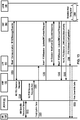
- a service request procedure e.g., a UE 100 triggered service request procedure may be used by a UE 100 in CM-IDLE state to request the establishment of a secure connection to an AMF 155.
- FIG. 11 is continuation of FIG. 10 depicting the service request procedure.
- the service request procedure may be used to activate a user plane connection for an established PDU session.
- the service request procedure may be triggered by the UE 100 or the 5GC, and may be used when the UE 100 is in CM-IDLE and/or in CM-CONNECTED and may allow selectively to activate user plane connections for some of the established PDU sessions.
- a UE 100 in CM IDLE state may initiate the service request procedure to send uplink signaling messages, user data, and/or the like, as a response to a network paging request, and/or the like.
- the AMF 155 may perform authentication.
- the UE 100 or network may send signaling messages, e.g. PDU session establishment from the UE 100 to a SMF 160, via the AMF 155.
- the AMF 155 may respond with a service accept message to synchronize PDU session status between the UE 100 and network.
- the AMF 155 may respond with a service reject message to the UE 100, if the service request may not be accepted by the network.
- the service reject message may include an indication or cause code requesting the UE 100 to perform a registration update procedure.
- network may take further actions if user plane connection activation may not be successful.
- more than one UPF e.g., old UPF 110-2 and PDU session Anchor PSA UPF 110-3 may be involved.
- the UE 100 may send to a (R)AN 105 an AN message comprising AN parameters, mobility management, MM NAS service request 1005 (e.g., list of PDU sessions to be activated, list of allowed PDU sessions, security parameters, PDU session status, and/or the like), and/or the like.
- the UE 100 may provide the list of PDU sessions to be activated when the UE 100 may re-activate the PDU session(s).
- the list of allowed PDU sessions may be provided by the UE 100 when the service request may be a response of a paging or a NAS notification, and may identify the PDU sessions that may be transferred or associated to the access on which the service request may be sent.
- the AN parameters may include selected PLMN ID, and an establishment cause.
- the establishment cause may provide the reason for requesting the establishment of an RRC connection.
- the UE 100 may send NAS service request message towards the AMF 155 encapsulated in an RRC message to the RAN 105.
- the UE 100 may identify, using the list of PDU sessions to be activated, the PDU session(s) for which the UP connections are to be activated in the NAS service request message. If the service request may be triggered for signaling, the UE 100 may not identify any PDU session(s). If this procedure may be triggered for paging response, and/or the UE 100 may have at the same time user data to be transferred, the UE 100 may identify the PDU session(s) whose UP connections may be activated in MM NAS service request message, by the list of PDU sessions to be activated.
- the NAS service request message may identify in the list of allowed PDU sessions the list of PDU sessions associated with the non-3GPP access that may be re-activated over 3GPP.
- the PDU session status may indicate the PDU sessions available in the UE 100.
- the UE 100 may not trigger the service request procedure for a PDU session corresponding to a LADN when the UE 100 may be outside the area of availability of the LADN. The UE 100 may not identify such PDU session(s) in the list of PDU sessions to be activated, if the service request may be triggered for other reasons.
- the (R)AN 105 may send to AMF 155 an N2 Message 1010 (e.g., a service request) comprising N2 parameters, MM NAS service request, and/or the like.
- the AMF 155 may reject the N2 message if it may not be able to handle the service request.
- the N2 parameters may include the 5G-GUTI, selected PLMN ID, location information, RAT type, establishment cause, and/or the like.
- the 5G-GUTI may be obtained in RRC procedure and the (R)AN 105 may select the AMF 155 according to the 5G-GUTI.
- the location information and RAT type may relate to the cell in which the UE 100 may be camping.
- the AMF 155 may initiate PDU session release procedure in the network for the PDU sessions whose PDU session ID(s) may be indicated by the UE 100 as not available.
- the AMF 155 may initiate a NAS authentication/security procedure 1015.
- the UE 100 may exchange NAS signaling.
- the AMF 155 may send to the SMF 160 a PDU session update context request 1020 e.g., Nsmf_PDUSession_UpdateSMContext request comprising PDU session ID(s), Cause(s), UE 100 location information, access type, and/or the like.
- PDU session update context request 1020 e.g., Nsmf_PDUSession_UpdateSMContext request comprising PDU session ID(s), Cause(s), UE 100 location information, access type, and/or the like.
- the Nsmf_PDUSession_UpdateSMContext request may be invoked by the AMF 155 if the UE 100 may identify PDU session(s) to be activated in the NAS service request message.
- the Nsmf_PDUSession_UpdateSMContext request may be triggered by the SMF 160 wherein the PDU session(s) identified by the UE 100 may correlate to other PDU session ID(s) than the one triggering the procedure.
- the Nsmf_PDUSession_UpdateSMContext request may be triggered by the SMF 160 wherein the current UE 100 location may be outside the area of validity for the N2 information provided by the SMF 160 during a network triggered service request procedure. The AMF 155 may not send the N2 information provided by the SMF 160 during the network triggered service request procedure.
- the AMF 155 may determine the PDU session(s) to be activated and may send a Nsmf_PDUSession_UpdateSMContext request to SMF 160(s) associated with the PDU session(s) with cause set to indicate establishment of user plane resources for the PDU session(s).
- the AMF 155 may notify the SMF 160 that the user plane for the PDU session may not be re-activated.
- the service request procedure may succeed without re-activating the user plane of any PDU sessions, and the AMF 155 may notify the UE 100.
- the SMF 160 may decide to (based on local policies) keep the PDU session, may reject the activation of user plane connection for the PDU session and may inform the AMF 155.
- the SMF 160 may notify the UPF 110 that originated the data notification to discard downlink data for the PDU sessions and/or to not provide further data notification messages.
- the SMF 160 may respond to the AMF 155 with an appropriate reject cause and the user plane activation of PDU session may be stopped.
- the SMF 160 may decide to (based on local policies) release the PDU session.
- the SMF 160 may locally release the PDU session and may inform the AMF 155 that the PDU session may be released.
- the SMF 160 may respond to the AMF 155 with an appropriate reject cause and the user plane Activation of PDU session may be stopped.
- the SMF 160 may check the UPF 110 Selection 1025 Criteria (e.g., slice isolation requirements, slice coexistence requirements, UPF's 110 dynamic load, UPF's 110 relative static capacity among UPFs supporting the same DNN, UPF 110 location available at the SMF 160, UE 100 location information, Capability of the UPF 110 and the functionality required for the particular UE 100 session.
- UPF 110 Selection 1025 Criteria e.g., slice isolation requirements, slice coexistence requirements, UPF's 110 dynamic load, UPF's 110 relative static capacity among UPFs supporting the same DNN, UPF 110 location available at the SMF 160, UE 100 location information, Capability of the UPF 110 and the functionality required for the particular UE 100 session.
- an appropriate UPF 110 may be selected by matching the functionality and features required for a UE 100, DNN, PDU session type (e.g.
- the SMF 160 may send to the UPF 110 (e.g., new intermediate UPF 110) an N4 session establishment request 1030.
- the SMF 160 may select a new UPF 110 to act as intermediate UPF 110-2 for the PDU session, or if the SMF 160 may select to insert an intermediate UPF 110 for a PDU session which may not have an intermediate UPF 110-2
- an N4 session establishment request 1030 message may be sent to the new UPF 110, providing packet detection, data forwarding, enforcement and reporting rules to be installed on the new intermediate UPF.
- the PDU session anchor addressing information (on N9) for this PDU session may be provided to the intermediate UPF 110-2.
- the SMF 160 may include a data forwarding indication.
- the data forwarding indication may indicate to the UPF 110 that a second tunnel endpoint may be reserved for buffered DL data from the old I-UPF.
- the new UPF 110 may send to SMF 160 an N4 session establishment response message 1030.
- the UPF 110 may allocate CN tunnel info
- the UPF 110 may provide DL CN tunnel info for the UPF 110 acting as PDU session anchor and UL CN tunnel info (e.g., CN N3 tunnel info) to the SMF 160.
- the new (intermediate) UPF 110 acting as N3 terminating point may send DL CN tunnel info for the old (intermediate) UPF 110-2 to the SMF 160.
- the SMF 160 may start a timer, to release the resource in the old intermediate UPF 110-2.
- the SMF 160 may select a new intermediate UPF 110 for the PDU session or may remove the old I-UPF 110-2, the SMF 160 may send N4 session modification request message 1035 to PDU session anchor, PSA UPF 110-3, providing the data forwarding indication and DL tunnel information from new intermediate UPF 110.
- the (PSA) UPF 110-3 may begin to send the DL data to the new I-UPF 110 as indicated in the DL tunnel information.
- the SMF 160 may include the data forwarding indication in the request.
- the data forwarding indication may indicate to the (PSA) UPF 110-3 that a second tunnel endpoint may be reserved for buffered DL data from the old I-UPF 110-2.
- the PSA UPF 110-3 may begin to buffer the DL data it may receive at the same time from the N6 interface.
- the PSA UPF 110-3 may send to the SMF 160 an N4 session modification response 1035.
- the PSA UPF 110-3 may become as N3 terminating point and may send CN DL tunnel info for the old (intermediate) UPF 110-2 to the SMF 160.
- the SMF 160 may start a timer, to release the resource in old intermediate UPF 110-2 if there is one.
- the SMF 160 may send to the old UPF 110-2 an N4 session modification request 1045 (e.g., may comprise new UPF 110 address, new UPF 110 DL tunnel ID, and/or the like).
- the SMF 160 may send the N4 session modification request message to the old (intermediate) UPF 110-2, and may provide the DL tunnel information for the buffered DL data. If the SMF 160 may allocate new I-UPF 110, the DL tunnel information is from the new (intermediate) UPF 110 may act as N3 terminating point.
- the DL tunnel information may be from the new UPF 110 (PSA) 110-3 acting as N3 terminating point.
- the SMF 160 may start a timer to monitor the forwarding tunnel.
- the old (intermediate) UPF 110-2 may send N4 session modification response message to the SMF 160.
- the old (intermediate) UPF 110-2 may forward its buffered data to the new (intermediate) UPF 110 acting as N3 terminating point.
- the old I-UPF 110-2 may be removed and the new I-UPF 110 may not be assigned for the PDU session and forwarding tunnel may be established to the UPF 110 (PSA) 110-3, the old (intermediate) UPF 110-2 may forward its buffered data to the UPF 110 (PSA) 110-3 acting as N3 terminating point.
- the SMF 160 may send to the AMF 155 an N11 message 1060 e.g., a Nsmf_PDUSession_UpdateSMContext response (comprising: N1 SM container (PDU session ID, PDU session re-establishment indication), N2 SM information (PDU session ID, QoS profile, CN N3 tunnel info, S-NSSAI), Cause), upon reception of the Nsmf_PDUSession_UpdateSMContext request with a cause including e.g., establishment of user plane resources.
- the SMF 160 may determine whether UPF 110 reallocation may be performed, based on the UE 100 location information, UPF 110 service area and operator policies.
- the SMF 160 may generate N2 SM information and may send a Nsmf_PDUSession_UpdateSMContext response 1060 to the AMF 155 to establish the user plane(s).
- the N2 SM information may contain information that the AMF 155 may provide to the RAN 105.
- the SMF 160 may reject the activation of UP of the PDU session by sending Nsmf_PDUSession_UpdateSMContext response that may contain N1 SM container to the UE 100 via the AMF 155.
- the N1 SM container may include the corresponding PDU session ID and PDU session re-establishment indication.
- the SMF 160 may invoke the Namf_Communication_N1N2MessageTransfer service operation to the AMF 155 to establish the user plane(s) for the PDU sessions. In an example, the SMF 160 may resume sending DL data notifications to the AMF 155 in case of DL data.
- the SMF 160 may send a message to the AMF 155 to reject the activation of UP of the PDU session by including a cause in the Nsmf_PDUSession_UpdateSMContext response if the PDU session may correspond to a LADN and the UE 100 may be outside the area of availability of the LADN, or if the AMF 155 may notify the SMF 160 that the UE 100 may be reachable for regulatory prioritized service, and the PDU session to be activated may not for a regulatory prioritized service; or if the SMF 160 may decide to perform PSA UPF 110-3 relocation for the requested PDU session.
- the AMF 155 may send to the (R)AN 105 an N2 request message 1065 (e.g., N2 SM information received from SMF 160, security context, AMF 155 signaling connection ID, handover restriction list, MM NAS service accept, list of recommended cells / TAs / NG-RAN node identifiers).
- the RAN 105 may store the security context, AMF 155 signaling connection Id, QoS information for the QoS flows of the PDU sessions that may be activated and N3 tunnel IDs in the UE 100 RAN 105 context.
- the MM NAS service accept may include PDU session status in the AMF 155.
- the MM NAS service accept may include the PDU session ID and the reason why the user plane resources may not be activated (e.g. LADN not available).
- Local PDU session release during the session request procedure may be indicated to the UE 100 via the session Status.
- the AMF 155 may not wait for responses from all SMF 160s before it may send N2 SM information to the UE 100.
- the AMF 155 may wait for all responses from the SMF 160s before it may send MM NAS service accept message to the UE 100.
- the AMF 155 may include at least one N2 SM information from the SMF 160 if the procedure may be triggered for PDU session user plane activation.
- AMF 155 may send additional N2 SM information from SMF 160s in separate N2 message(s) (e.g. N2 tunnel setup request), if there is any.
- the AMF 155 may send one N2 request message to (R)AN 105 after all the Nsmf_PDUSession_UpdateSMContext response service operations from all the SMF 160s associated with the UE 100 may be received.
- the N2 request message may include the N2 SM information received in each of the Nsmf_PDUSession_UpdateSMContext response and PDU session ID to enable AMF 155 to associate responses to relevant SMF 160.
- the AMF 155 may include the information from the list in the N2 request.
- the RAN 105 may use this information to allocate the RAN 105 notification area when the RAN 105 may decide to enable RRC inactive state for the UE 100.
- the AMF 155 may receive an indication, from the SMF 160 during a PDU session establishment procedure that the UE 100 may be using a PDU session related to latency sensitive services, for any of the PDU sessions established for the UE 100 and the AMF 155 has received an indication from the UE 100 that may support the CM-CONNECTED with RRC inactive state, then the AMF 155 may include the UE's RRC inactive assistance information.
- the AMF 155 based on network configuration, may include the UE's RRC inactive assistance information.
- the (R)AN 105 may send to the UE 100 a message to perform RRC connection reconfiguration 1070 with the UE 100 depending on the QoS information for all the QoS flows of the PDU sessions whose UP connections may be activated and data radio bearers.
- the user plane security may be established.
- the RAN 105 may forward the MM NAS service accept to the UE 100.
- the UE 100 may locally delete context of PDU sessions that may not be available in 5GC.
- the UE 100 may initiate PDU session re-establishment for the PDU session(s) that may be re-established after the service request procedure may be complete.
- the uplink data from the UE 100 may be forwarded to the RAN 105.
- the RAN 105 e.g., NG-RAN
- the RAN 105 may send the uplink data to the UPF 110 address and tunnel ID provided.
- the (R)AN 105 may send to the AMF 155 an N2 request Ack 1105 (e.g., N2 SM information (comprising: AN tunnel info, list of accepted QoS flows for the PDU sessions whose UP connections are activated, list of rejected QoS flows for the PDU sessions whose UP connections are activated)).
- N2 request message may include N2 SM information(s), e.g. AN tunnel info.
- RAN 105 may respond N2 SM information with separate N2 message (e.g. N2 tunnel setup response).
- the N2 request Ack may include multiple N2 SM information and information to enable the AMF 155 to associate the responses to relevant SMF 160.
- the AMF 155 may send to the SMF 160 a Nsmf_PDUSession_UpdateSMContext request 1110 (N2 SM information (AN tunnel info), RAT type) per PDU session. If the AMF 155 may receive N2 SM information (one or multiple) from the RAN 105, then the AMF 155 may forward the N2 SM information to the relevant SMF 160. If the UE 100 time zone may change compared to the last reported UE 100 Time Zone, then the AMF 155 may include the UE 100 time zone IE in the Nsmf_PDUSession_UpdateSMContext request message.
- the SMF 160 may initiate notification about new location information to the PCF 135 (if subscribed) by invoking an event exposure notification operation (e.g., a Nsmf_EventExposure_Notify service operation).
- the PCF 135 may provide updated policies by invoking a policy control update notification message 1115 (e.g., a Npcf_SMPolicyControl_UpdateNotify operation).
- the SMF 160 may select a new UPF 110 to act as intermediate UPF 110 for the PDU session, the SMF 160 may initiates an N4 session modification procedure 1120 to the new I-UPF 110 and may provide AN tunnel info.
- the downlink data from the new I-UPF 110 may be forwarded to RAN 105 and UE 100.
- the UPF 110 may send to the SMF 160, an N4 session modification response 1120.
- the SMF 160 may send to the AMF 155, a Nsmf_PDUSession_UpdateSMContext response 1140.
- the SMF 160 may sends N4 session modification request 1145 to new (intermediate) UPF 110 acting as N3 terminating point to release the forwarding tunnel.
- the new (intermediate) UPF 110 may send to the SMF 160 an N4 session modification response 1145.
- the SMF 160 may send to the PSA UPF 110-3 an N4 session modification request 1150, or N4 session release request.
- the SMF 160 may send an N4 session modification request 1155, providing AN tunnel info.
- the SMF 160 may select a new UPF 110 to act as intermediate UPF 110, and the old UPF 110-2 may not be PSA UPF 110-3, the SMF 160 may initiate resource release, after timer expires, by sending an N4 session release request (release cause) to the old intermediate UPF 110-2.
- the old intermediate UPF 110-2 may send to the SMF 160 an N4 session modification response or N4 session release response 1155.
- the old UPF 110-2 may acknowledge with the N4 session modification response or N4 session release response message to confirm the modification or release of resources.
- the AMF 155 may invoke the Namf_EventExposure_Notify service operation to notify the mobility related events, after this procedure may complete, towards the NFs that may have subscribed for the events.
- the AMF 155 may invoke the Namf_EventExposure_Notify towards the SMF 160 if the SMF 160 had subscribed for UE 100 moving into or out of area of interest and if the UE's current location may indicate that it may be moving into or moving outside of the area of interest subscribed, or if the SMF 160 had subscribed for LADN DNN and if the UE 100 may be moving into or outside of an area where the LADN is available, or if the UE 100 may be in MICO mode and the AMF 155 had notified an SMF 160 of the UE 100 being unreachable and that SMF 160 may not send DL data notifications to the AMF 155, and the AMF 155 may informs the SMF 160 that the UE 100 is reachable, or if the SMF 160 had subscribed for UE 100 reachability status, then the AMF 155 may notify the UE 100 reachability.
- the UE 100 may send to the AMF 155 a NAS Message 1205 (or a SM NAS message) comprising NSSAI, S-NSSAI (e.g., requested S-NSSAI, allowed S-NSSAI, subscribed S-NSSAI, and/or the like), DNN, PDU session ID, request type, old PDU session ID, N1 SM container (PDU session establishment request), and/or the like.
- the UE 100 in order to establish a new PDU session, may generate a new PDU session ID.
- the UE 100 may initiate the UE 100 requested PDU session establishment procedure with a request type indicating emergency request.
- the UE 100 may initiate the UE 100 requested PDU session establishment procedure by the transmission of the NAS message containing a PDU session establishment request within the N1 SM container.
- the PDU session establishment request may include a PDU type, SSC mode, protocol configuration options, and/or the like.
- the request type may indicate initial request if the PDU session establishment is a request to establish the new PDU session and may indicate existing PDU session if the request refers to an existing PDU session between 3GPP access and non-3GPP access or to an existing PDN connection in EPC.
- the request type may indicate emergency request if the PDU session establishment may be a request to establish a PDU session for emergency services.
- the request type may indicate existing emergency PDU session if the request refers to an existing PDU session for emergency services between 3GPP access and non-3GPP access.
- the NAS message sent by the UE 100 may be encapsulated by the AN in a N2 message towards the AMF 155 that may include user location information and access technology type information.
- the PDU session establishment request message may contain SM PDU DN request container containing information for the PDU session authorization by the external DN.
- the UE 100 may include the old PDU session ID which may indicate the PDU session ID of the ongoing PDU session to be released, in the NAS message.
- the old PDU session ID may be an optional parameter which may be included in this case.
- the AMF 155 may receive from the AN the NAS message (e.g., NAS SM message) together with user location information (e.g. cell ID in case of the RAN 105).
- the UE 100 may not trigger a PDU session establishment for a PDU session corresponding to a LADN when the UE 100 is outside the area of availability of the LADN.
- the AMF 155 may determine that the NAS message or the SM NAS message may correspond to the request for the new PDU session based on that request type indicates initial request and that the PDU session ID may not be used for any existing PDU session(s) of the UE 100. If the NAS message does not contain an S-NSSAI, the AMF 155 may determine a default S-NSSAI for the requested PDU session either according to the UE 100 subscription, if it may contain only one default S-NSSAI, or based on operator policy. In an example, the AMF 155 may perform SMF 160 selection 1210 and select an SMF 160.
- the AMF 155 may store an association of the S-NSSAI, the PDU session ID and a SMF 160 ID. In an example, if the request type is initial request and if the old PDU session ID indicating the existing PDU session may be contained in the message, the AMF 155 may select the SMF 160 and may store an association of the new PDU session ID and the selected SMF 160 ID.
- the AMF 155 may send to the SMF 160, an N11 message 1215, e.g., Nsmf_PDUSession_CreateSMContext request (comprising: SUPI or PEI, DNN, S-NSSAI, PDU session ID, AMF 155 ID, request type, N1 SM container (PDU session establishment request), user location information, access type, PEI, GPSI), or Nsmf_PDUSession_UpdateSMContext request (SUPI, DNN, S-NSSAI, PDU session ID, AMF 155 ID, request type, N1 SM container (PDU session establishment request), user location information, access type, RAT type, PEI).
- Nsmf_PDUSession_CreateSMContext request comprising: SUPI or PEI, DNN, S-NSSAI, PDU session ID, AMF 155 ID, request type, N1 SM container (PDU session establishment request), user location information, access type, RAT type, PEI).
- the AMF 155 may invoke the Nsmf_PDUSession_CreateSMContext request, but if the AMF 155 already has an association with an SMF 160 for the PDU session ID provided by the UE 100 (e.g. when request type indicates existing PDU session), the AMF 155 may invoke the Nsmf_PDUSession_UpdateSMContext request.
- the AMF 155 ID may be the UE's GUAMI which uniquely identifies the AMF 155 serving the UE 100.
- the AMF 155 may forward the PDU session ID together with the N1 SM container containing the PDU session establishment request received from the UE 100.
- the AMF 155 may provide the PEI instead of the SUPI when the UE 100 has registered for emergency services without providing the SUPI. In case the UE 100 has registered for emergency services but has not been authenticated, the AMF 155 may indicate that the SUPI has not been authenticated.
- the SMF 160 may register with the UDM 140, and may retrieve subscription data 1225 and subscribes to be notified when subscription data may be modified.
- the SMF 160 may determine that the request may be due to handover between 3GPP access and non-3GPP access or due to handover from EPS. The SMF 160 may identify the existing PDU session based on the PDU session ID.
- the SMF 160 may not create a new SM context but instead may update the existing SM context and may provide the representation of the updated SM context to the AMF 155 in the response. if the request type may be initial request and if the old PDU session ID may be included in Nsmf_PDUSession_CreateSMContext request, the SMF 160 may identify the existing PDU session to be released based on the old PDU session ID.
- the SMF 160 may send to the AMF 155, the N11 message response 1220, e.g., either a PDU session create/update response, Nsmf_PDUSession_CreateSMContext response 1220 (cause, SM context ID or N1 SM container (PDU session reject(cause))) or a Nsmf_PDUSession_UpdateSMContext response.
- the N11 message response 1220 e.g., either a PDU session create/update response, Nsmf_PDUSession_CreateSMContext response 1220 (cause, SM context ID or N1 SM container (PDU session reject(cause))) or a Nsmf_PDUSession_UpdateSMContext response.
- the SMF 160 may perform secondary authorization/authentication 1230 during the establishment of the PDU session by a DN-AAA server, the SMF 160 may select a UPF 110 and may trigger a PDU session establishment authentication/authorization.
- the SMF 160 may select an SSC mode for the PDU session.
- the SMF 160 may select one or more UPFs as needed.
- the SMF 160 may allocate an IP address/prefix for the PDU session.
- the SMF 160 may allocate an interface identifier to the UE 100 for the UE 100 to build its link-local address.
- the SMF 160 may allocate an IPv6 prefix for the PDU session and N6 point-to-point tunneling (based on UDP/IPv6).
- the may SMF 160 performs PCF 135 selection 1235. If the request type indicates existing PDU session or existing emergency PDU session, the SMF 160 may use the PCF 135 already selected for the PDU session. If dynamic PCC is not deployed, the SMF 160 may apply local policy.
- the SMF 160 may perform a session management policy establishment procedure 1240 to establish a PDU session with the PCF 135 and may get the default PCC Rules for the PDU session.
- the GPSI may be included if available at the SMF 160. If the request type in 1215 indicates existing PDU session, the SMF 160 may notify an event previously subscribed by the PCF 135 by a session management policy modification procedure and the PCF 135 may update policy information in the SMF 160.
- the PCF 135 may provide authorized session-AMBR and the authorized 5QI and ARP to SMF 160.
- the PCF 135 may subscribe to the IP allocation/release event in the SMF 160 (and may subscribe other events).
- the PCF 135, based on the emergency DNN, may set the ARP of the PCC rules to a value that may be reserved for emergency services.
- the SMF 160 may select an SSC mode for the PDU session.
- the SMF 160 may select 1245 one or more UPFs as needed.
- the SMF 160 may allocate an IP address/prefix for the PDU session.
- the SMF 160 may allocate an interface identifier to the UE 100 for the UE 100 to build its link-local address.
- the SMF 160 may allocate an IPv6 prefix for the PDU session and N6 point-to-point tunneling (e.g., based on UDP/IPv6).
- N6 point-to-point tunneling e.g., based on UDP/IPv6.
- Ethernet PDU type PDU session neither a MAC nor an IP address may be allocated by the SMF 160 to the UE 100 for this PDU session.
- the SMF 160 may maintain the same IP address/prefix that may be allocated to the UE 100 in the source network.
- the SMF 160 may maintain the SSC mode of the PDU session, e.g., the current PDU session Anchor and IP address.
- the SMF 160 may trigger e.g. new intermediate UPF 110 insertion or allocation of a new UPF 110.
- the SMF 160 may select 1245 the UPF 110 and may select SSC mode 1.
- the SMF 160 may perform a session management policy modification 1250 procedure to report some event to the PCF 135 that has previously subscribed. If request type is initial request and dynamic PCC is deployed and PDU type is IPv4 or IPv6, the SMF 160 may notify the PCF 135 (that has previously subscribed) with the allocated UE 100 IP address/prefix.
- the PCF 135 may provide updated policies to the SMF 160.
- the PCF 135 may provide authorized session-AMBR and the authorized 5QI and ARP to the SMF 160.
- the SMF 160 may initiate an N4 session establishment procedure 1255 with the selected UPF 110.
- the SMF 160 may initiate an N4 session modification procedure with the selected UPF 110.
- the SMF 160 may send an N4 session establishment/modification request 1255 to the UPF 110 and may provide packet detection, enforcement, reporting rules, and/or the like to be installed on the UPF 110 for this PDU session.
- CN tunnel info is allocated by the SMF 160, the CN tunnel info may be provided to the UPF 110.
- the SMF 160 may determine the Inactivity Timer and may provide it to the UPF 110.
- the UPF 110 may acknowledges by sending an N4 session establishment/modification response 1255. If CN tunnel info is allocated by the UPF, the CN tunnel info may be provided to SMF 160. In an example, if multiple UPFs are selected for the PDU session, the SMF 160 may initiate N4 session establishment/modification procedure 1255 with each UPF 110 of the PDU session.
- the SMF 160 may send to the AMF 155 an Namf_Communication_N1N2MessageTransfer 1305 message (comprising PDU session ID, access type, N2 SM information (PDU session ID, QFI(s), QoS profile(s), CN tunnel info, S-NSSAI, session-AMBR, PDU session type, and/or the like), N1 SM container (PDU session establishment accept (QoS Rule(s), selected SSC mode, S-NSSAI, allocated IPv4 address, interface identifier, session-AMBR, selected PDU session type, and/or the like))).
- N2 SM information PDU session ID, QFI(s), QoS profile(s), CN tunnel info, S-NSSAI, session-AMBR, PDU session type, and/or the like
- N1 SM container PDU session establishment accept (QoS Rule(s), selected SSC mode, S-NSSAI, allocated IPv4 address, interface identifier, session-AMBR, selected PDU
- the CN tunnel info may comprise tunnel information related with the UPF 110 that terminates N3.
- the N2 SM information may carry information that the AMF 155 may forward to the (R)AN 105 (e.g., the CN tunnel info corresponding to the core network address of the N3 tunnel corresponding to the PDU session, one or multiple QoS profiles and the corresponding QFIs may be provided to the (R)AN 105, the PDU session ID may be used by AN signaling with the UE 100 to indicate to the UE 100 the association between AN resources and a PDU session for the UE100, and/or the like).
- a PDU session may be associated to an S-NSSAI and a DNN.
- the N1 SM container may contain the PDU session establishment accept that the AMF 155 may provide to the UE 100.
- multiple QoS rules and QoS profiles may be included in the PDU session establishment accept within the N1 SM and in the N2 SM information.
- the Namf_Communication_N1N2MessageTransfer 1305 may further comprise the PDU session ID and information allowing the AMF 155 to know which access towards the UE 100 to use.
- the AMF 155 may send to the (R)AN105 an N2 PDU session request 1310 (comprising N2 SM information, NAS message (PDU session ID, N1 SM container (PDU session establishment accept, and/or the like))).
- the AMF 155 may send the NAS message 1310 that may comprise PDU session ID and PDU session establishment accept targeted to the UE 100 and the N2 SM information received from the SMF 160 within the N2 PDU session request 1310 to the (R)AN 105.
- the (R)AN 105 may issue AN specific signaling exchange 1315 with the UE 100 that may be related with the information received from SMF 160.
- an RRC connection reconfiguration procedure may take place with the UE 100 to establish the necessary RAN 105 resources related to the QoS Rules for the PDU session request 1310.
- (R)AN 105 may allocate (R)AN 105 N3 tunnel information for the PDU session.
- the master RAN 105 node may assign some (zero or more) QFIs to be setup to a master RAN 105 node and others to the secondary RAN 105 node.
- the AN tunnel info may comprise a tunnel endpoint for each involved RAN 105 node, and the QFIs assigned to each tunnel endpoint.
- a QFI may be assigned to either the master RAN 105 node or the secondary RAN 105 node.
- (R)AN 105 may forward the NAS message 1310 (PDU session ID, N1 SM container (PDU session establishment accept)) to the UE 100.
- the (R)AN 105 may provide the NAS message to the UE 100 if the necessary RAN 105 resources are established and the allocation of (R)AN 105 tunnel information are successful.
- the N2 PDU session response 1320 may comprise a PDU session ID, cause, N2 SM information (PDU session ID, AN tunnel info, list of accepted/rejected QFI(s)), and/or the like.
- the AN tunnel info may correspond to the access network address of the N3 tunnel corresponding to the PDU session.
- the AMF 155 may forward the N2 SM information received from (R)AN 105 to the SMF 160 via a Nsmf_PDUSession_UpdateSMContext request 1330 ( comprising: N2 SM information, request type, and/or the like).
- a Nsmf_PDUSession_UpdateSMContext request 1330 comprising: N2 SM information, request type, and/or the like.
- the SMF 160 may release the rejected QFI(s) associated QoS profiles.
- the SMF 160 may initiate an N4 session modification procedure 1335 with the UPF110.
- the SMF 160 may provide AN tunnel info to the UPF 110 as well as the corresponding forwarding rules.
- the UPF 110 may provide an N4 session modification response 1335 to the SMF 160160.
- the SMF 160 may send to the AMF 155 a Nsmf_PDUSession_UpdateSMContext response 1340 (Cause).
- the SMF 160 may subscribe to the UE 100 mobility event notification from the AMF 155 (e.g. location reporting, UE 100 moving into or out of area of interest), after this step by invoking Namf_EventExposure_Subscribe service operation.
- the SMF 160 may subscribe to the UE 100 moving into or out of LADN service area event notification by providing the LADN DNN as an indicator for the area of interest.
- the AMF 155 may forward relevant events subscribed by the SMF 160.
- the SMF 160 may send to the AMF 155, a Nsmf_PDUSession_SMContextStatusNotify (release) 1345.
- the SMF 160 may inform the AMF 155 by invoking Nsmf_PDUSession_SMContextStatusNotify(release) 1345.
- the SMF 160 may releases any N4 session(s) created, any PDU session address if allocated (e.g. IP address) and may release the association with the PCF 135.
- the SMF 160 may generate an IPv6 Router Advertisement 1350 and may send it to the UE 100 via N4 and the UPF 110.
- the SMF 160 may unsubscribe 1360 to the modifications of session management subscription data for the corresponding (SUPI, DNN, S-NSSAI), using Nudm_SDM_Unsubscribe (SUPI, DNN, S-NSSAI), if the SMF 160 is no more handling a PDU session of the UE 100 for this (DNN, S-NSSAI).
- the SMF 160 may deregister 1360 for the given PDU session using Nudm_UECM_Deregistration (SUPI, DNN, PDU session ID).
- FIG. 14 depicts an example architecture of a 5G communication system as per an aspect of an embodiment of the present disclosure.
- the 5G system comprises a 5G Core Network (5GC) and a Next Generation Radio Access Network (NG-RAN).
- the NG-RAN may be a base station of 5G system and may comprise a gNB, an ng-eNB and/or the like.
- the gNB may provide new radio (NR) user plane and control plane protocol that terminates towards a wireless device (e.g. UE).
- the ng-eNB may provide Evolved Universal Terrestrial Radio Access (E-UTRA) user plane and control plane protocol terminations towards the wireless device.
- E-UTRA Evolved Universal Terrestrial Radio Access
- the gNBs and ng-eNBs may be interconnected with each other via one or more Xn interfaces.
- the gNBs and ng-eNBs may be also connected to the 5GC via one or more NG interfaces (e.g. to an AMF
- a satellite may be a space-borne vehicle embarking a bent pipe payload or a regenerative payload telecommunication transmitter.
- the satellite may be placed into a low-earth orbit (LEO) at an altitude between 300 km to 1500 km, a medium-earth orbit (MEO) at an altitude between 8000 to 20000 km, or a geostationary satellite earth orbit (GEO) at 35,786 km altitude.
- LEO low-earth orbit
- MEO medium-earth orbit
- GEO geostationary satellite earth orbit
- a satellite network may be a network or network segment that uses a space-borne vehicle to embark a transmission equipment relay node or a base station.
- a terrestrial network is a network located on the surface of the earth
- NTN non-terrestrial network
- NTN non-terrestrial network
- FIGS. 15A and 15B are examples of NTN architectures in which a satellite is used as part of a network as per embodiments of the present disclosure.
- FIG. 15A shows an example NTN architecture corresponding to a transparent satellite model.
- the NTN architecture of FIG. 15A comprises a wireless device, a satellite, an NTN gateway, a base station, a 5G core network, and a data network.
- the satellite may behave as a remote radio unit (RRU) communicating with the NTN gateway.
- RRU remote radio unit
- the NTN gateway may connect to a base station on the ground.
- the wireless device may transmit and receive via the satellite and the satellite may implement frequency conversion and radio frequency amplification in both the uplink and downlink directions.
- the satellite may correspond to an analogue RF repeater that repeats the NR-Uu radio interface from a service link (between the satellite and the wireless device) to a feeder link (between the NTN gateway and the satellite), and vice-versa.
- FIG. 15B shows an example NTN architecture regarding corresponding to a regenerative satellite model.
- the NTN architecture of FIG. 15B comprises a wireless device, a satellite, an NTN gateway, a 5G core network, and/or the like.
- the satellite may regenerate signals received from earth (e.g. from a wireless device or from an NTN gateway). In an example, the satellite may behave as a base station.
- FIG. 16 depicts an example wireless network architecture in which a satellite is used as part of a backhaul interface as per embodiments of the disclosure.
- the NTN architecture of FIG. 16 comprises a wireless device, an access network/base station, a satellite, a 5G core network, and a data network.
- the access network/base station is a terrestrial access network which is located on a surface of the earth.
- the access network may also have an NTN architecture analogous to the NTN architectures shown in, for example, FIGS. 15A and/or 15B.
- the 5G core network may also be located on a surface of the earth.
- the wireless device may communicate with the access network/base station.
- the access network/base station may communicate with the 5G core network via a satellite radio interface (e.g., a satellite backhaul).
- the satellite radio interface may provide a transport for next generation (NG) reference points (e.g. N2/N3) between the terrestrial access network and the 5G core network.
- NG next generation
- the satellite may transparently carry the communication payload of the NG reference points.
- FIG. 17 depicts earth orbits of example satellites.
- a low earth orbit (LEO) orbits earth with an altitude ranging from 300km to 1500km above the surface of the earth.
- An orbital period of the LEO may be between about 84 minutes and 127 minutes.
- mean orbital velocity needed to maintain a stable LEO may be 7.8 km/s and may be reduced with increased orbital altitude.
- mean orbital velocity for circular orbit of 200 km may be 7.79 km/s.
- mean orbital velocity for circular orbit 1500 km may be 7.12 km/s.
- a geostationary satellite earth orbit (GEO) orbits earth with an altitude 35,786 km above the surface of the earth.
- the GEO may be established at an altitude very close to 35,786 km (22,236 mi) and directly above the equator. This equates to an orbital velocity of 3.07 km/s (1.91 mi/s) and an orbital period of 1,436 minutes, which equates to almost one sidereal day (23.934461223 hours). From the perspective of a given point on the surface of the earth, the position of the LEO satellite may change, while the position of the GEO may not move.
- FIG. 18 shows different types of non-terrestrial networks comprising low earth orbiting (LEO) satellites, medium earth orbiting (MEO) satellites, geostationary earth orbiting (GEO), unmanned aircraft system (UAS) and highly elliptical orbiting (HEO) satellites.
- LEO low earth orbiting
- MEO medium earth orbiting
- GEO geostationary earth orbiting
- UAS unmanned aircraft system
- HEO highly elliptical orbiting
- the typical beam footprint size of the GEO satellite is 200 ⁇ 1000km.
- the footprint of a communications satellite may be the ground area that its transponders offer coverage and determines the satellite dish diameter required to receive each transponder's signal.
- the transponders may be a wireless device.
- Propagation delay may be the amount of time it takes for the head of the signal to travel from a sender to a receiver or vice versa.
- the sender may be a wireless device and the receiver may be a base station/access network.
- the sender may be a base station/access network and the receiver may be a wireless device.
- the propagation delay may vary depending on a distance between the sender and the receiver.
- FIG. 19 shows examples of propagation delay corresponding to NTNs of different altitudes.
- the propagation delay of this example figure is one-way latency.
- one-way latency is an amount of time required to propagate through a telecommunication system from a terminal to the receiver (e.g. base station, eNB, gNB, RRU of a base station).
- the round-trip propagation delay including service link (e.g. between the satellite and the wireless device) and feeder link (e.g. between the NTN gateway and the satellite) may be four times of 138.9 milliseconds (approximately 556 milliseconds).
- the round-trip delay of the GEO satellite may be more than a few seconds.
- terrestrial network e.g. NR, E-UTRA, LTE
- the round-trip delay of the GEO satellite may be more than a few seconds.
- terrestrial network e.g. NR, E-UTRA, LTE
- terrestrial network round-trip propagation delay may negligible.
- terrestrial network round-trip propagation delay may be less than 1 millisecond.
- the GEO satellite round-trip delay may be hundreds of times longer than the one of terrestrial network.
- FIG. 20 is an example architecture of a 5G system having a 5G core network that provides service to different types of access networks as per an aspect of an embodiment of the present disclosure.
- the different types of access networks may include terrestrial access networks and non-terrestrial access networks.
- An ng-eNB may constitute a type of terrestrial access network and a gNB may constitute another type of terrestrial access network.
- a non-GEO (e.g. LEO) satellite may a type of non-terrestrial access network and a GEO satellite may constitute another type of non-terrestrial access network.
- the 5G core network may operate multiple access networks which have different physical perspectives (e.g. latency, throughput, delay).
- FIG. 21 depicts an architecture (left side) and coverage map (right side) of a deployment scenario in which one public land mobile network (e.g. PLMN A) provides both a non-terrestrial access network and a terrestrial access network.
- PLMN A public land mobile network
- a wireless device may be able to access the non-terrestrial access network and the terrestrial access network.
- separate NG instances e.g. N2, N3 are handling separate access type nodes.
- the coverage of the non-terrestrial access network may span over the coverage of the terrestrial access network.
- the PLMN A is a Verizon, AT&T and/or the like.
- Verizon may deploy a cellular access network (e.g.
- a wireless device which is a subscriber of Verizon may access to a core network via the terrestrial access network when the wireless device is in a coverage area of the terrestrial access network.
- urban area or suburban area may be the coverage area of the terrestrial access network.
- the wireless device may access the core network via the non-terrestrial access network when the wireless device is out of coverage area of the terrestrial access network.
- the rural area or mountain area may be out of the terrestrial access network coverage.
- FIG. 22 depicts an architecture (left side) and coverage map (right side) of a scenario in which two different public land mobile networks (e.g. PLMN A and PLMN B) respectively provide a non-terrestrial access network and a terrestrial access network.
- the PLMN B is a Verizon, AT&T and/or the like.
- the PLMN B is an Iridium communication.
- Verizon may have roaming agreement with non-terrestrial network operator Iridium communication.
- a wireless device which is subscriber of the Verizon may access Verizon terrestrial access network if the wireless device resides in the coverage of the terrestrial access network. The wireless device may roam to the non-terrestrial access network, PLMN B, if the wireless device is out of coverage of the terrestrial access network.
- FIG. 23 depicts an example control plane protocol stack between a wireless device and various network functions (e.g. AMF, SMF).
- the wireless device is a user equipment (UE).
- the wireless device is a transponder.
- NAS non-access stratum
- MM Mobility management
- UE user equipment
- AMF access and mobility management function
- Session management may be between the user equipment (UE) and the session management function (SMF) for both 3GPP access and non-3GPP access.
- NAS-MM is protocol interface between the UE and the AMF.
- NAS-SM is protocol interface between the UE and the SMF.
- the main function of the mobility management (5GMM) sublayer is to support the identification, security, mobility of a UE as well as generic message transport.
- the main function of the 5GSM sublayer is to support the packet data unit (PDU) session handling in the UE and in the SMF (transferred via the AMF).
- the 5GSM may comprises procedure for an authentication and authorization, establishment, modification and release of PDU sessions.
- the UE (wireless device) and the network functions may maintain and control non-access stratum (NAS) timers for each NAS procedure in order to handle abnormal cases and proper operations.
- NAS timers for mobility management
- NAS timers for session management.
- the UE may start a NAS timer when the UE starts a NAS procedure (e.g. registration procedure, service request procedure).
- the UE may start the NAS timer in response to sending a NAS request message to a network function (e.g. AMF, SMF, PCF).
- AMF Access Management Function
- the UE If the UE does not receive a NAS response message corresponding to the NAS request message from the network function before an expiration of the NAS timer (before timeout of the NAS period), the UE aborts the ongoing NAS procedure.
- the UE may also determine to retransmit (re-send) the NAS request message after a pause. A period of the pause may be determined by another NAS timer.
- a wireless device may determine a retransmission (re-sending) of the NAS request message based on the expiration of the NAS timer.
- FIGS. 24 and 25 illustrate usage of NAS timers in the context of a registration procedure, in which a UE sends a registration request message for mobility and periodic registration to an AMF via an access network.
- FIG. 24 illustrates a successful case in which the UE receives a response message from an AMF before a timeout (expiration) of the NAS timer.
- FIG. 25 is a case in which the UE does not receive a response message.
- FIG. 24 illustrates a registration procedure in which a UE attempts to register with an AMF.
- the UE sends a registration request message to the AMF requesting a registration of the UE.
- the registration request message may comprise a registration type, a UE identity (e.g., SUCI, 5G-GUTI), the location of the UE (e.g., last visited TAI), requested NSSAI, UE mobility management context information, information for the MICO mode usage, and/or the like.
- the registration type may indicate a mobility or periodic registration.
- the UE may start a first NAS timer referred to as UE NAS timer A.
- the UE NAS timer A may be started simultaneously with or in response to the sending of the registration request message.
- the access stratum layer of the UE may perform a random-access procedure to establish a radio resource control (RRC) connection setup with an access network.
- RRC radio resource control
- the AMF may send a registration accept message to the UE.
- the registration accept message may comprise 5G-GUTI, registration area, a periodic registration area update time value, a MICO mode indication, and/or the like.
- the AMF may start a timer simultaneous with or in response to the sending of the registration accept message.
- This timer may be referred to as AMF NAS timer A, and may correspond to the timer T3550 identified in the 3GPP standards.
- the UE may stop the UE NAS timer A in response to receiving the registration accept message is received successfully from the AMF (as shown in FIG. 24 ).
- the registration accept message comprising a temporary identity (e.g. 5G-GUTI)
- the UE may send a registration complete message to the AMF.
- the AMF may stop the AMF NAS timer A in response to receiving the registration complete message from the UE.
- the AMF may reject the registration procedure by sending a registration reject message to the UE.
- the AMF may reject the registration if, for example, there is congestion when the registration request message is received.
- the UE may stop the UE NAS timer A in response to receiving the registration request message.
- the subsequent behavior of the UE may be based on a cause value in the registration reject message.
- FIG. 25 illustrates another registration procedure in which a UE attempts to register with an AMF.
- the UE may send a registration request message analogous to the registration request message shown in FIG. 24 .
- the UE may also start the UE NAS timer A.
- the period of the UE NAS timer A may be 15 seconds.
- the NAS timer expires while the UE is waiting for an NAS response message (e.g. registration accept, registration reject).
- the UE starts a second NAS timer, referred to in the present example as UE NAS timer B.
- the UE may increase a registration attempt counter and may re-send (retransmit) the registration request message and restart the UE NAS timer A. If a registration accept message is received in response to the retransmission of the request (as shown in FIG. 25 ), then the UE NAS timer A stops. If no registration accept message is received and the registration attempt counter reaches or exceeds a predefined value (e.g., 5), the UE may abort the ongoing procedure (not shown in FIG. 25 ).
- a predefined value e.g., 5
- a NAS procedure such as service request procedure, one NAS timer (e.g. first NAS timer) may be used to abort the NAS procedure.
- retransmission of the same NAS request message may not happen for the service request procedure based on an expiration of the first NAS timer.
- the UE may abort the service request procedure in response to the expiration of the first NAS timer.
- a UE may send another service request message in response to upper layer request.
- a service request for service A is aborted in response to an expiration of a first NAS timer.
- the wireless may send a service request message in response to a connection request for service B from an upper layer of the UE.
- the upper layer of a UE may be application layer of the UE.
- non-access stratum (NAS) handling may be access agnostic, for example, when an AMF supports multiple access technologies.
- a wireless device may access a 5G core (e.g. AMF) via a base station employing NR (gNB).
- the wireless device may access a 5G core (e.g. AMF) via a base station employing E-UTRA (ng-eNB).
- E-UTRA ng-eNB
- the wireless device may adopt the same NAS timings (e.g., the periods/values of one or more NAS timers).
- a wireless device may start a NAS procedure (e.g., registration procedure, service request, and/or the like) by sending a NAS request message (e.g., registration request message, service request message, and/or the like) to an AMF.
- the wireless device may start a first NAS period (e.g., corresponding to UE NAS timer A) when sending the NAS request message.
- the first NAS period may correspond to a preconfigured value (e.g., 15 seconds).
- the wireless device may determine that the NAS procedure has failed if the wireless device does not receive a NAS response message prior to an expiration of the first NAS period.
- the wireless device may abort the NAS procedure (e.g.
- the wireless device may abort the NAS procedure (e.g. registration procedure) and start a second NAS period (e.g., corresponding to UE NAS timer B) when the first NAS period expires.
- the second NAS period may be, for example, 10 seconds.
- the wireless device may send a second NAS request message when the second NAS period expires and may abort the NAS procedure after a number of failed attempts.
- Configuration of NAS timers in existing technologies may result in high signaling overhead and excessive connection failure when multiple access technologies are implemented in a wireless device.
- the wireless device may experience increased connection failures because of expiry of NAS timers.
- incomplete NAS registration procedures may result in increased connections failures when the wireless device connect to the 5G network.
- NTN non-terrestrial networks
- Example embodiments enhances NAS timer configurations to reduce connections failures during the access procedures.
- Example embodiment takes into account relatively longer propagation delays non-terrestrial networks (NTN) to enhance NAS timer configuration.
- Example embodiments implement enhanced timer management processes for NAS procedures to reduce connection failure and signaling overhead.
- the enhanced timer management processes of the present disclosure may accommodate a wider variety of access types.
- the example embodiments may reduce expiry of a NAS timer before receiving the registration accept message and allow reasonably long delay for a response to arrive.
- one or more public land mobile network may employ non-terrestrial network (NTN), terrestrial network, or both.
- NTN non-terrestrial network
- the PLMN may employ the NTN for a Uu interface between a wireless device and an access network (e.g. base station, gNB).
- the PLMN may employ the NTN for backhaul interface (e.g. NG interface, N2/N3 interface) between an access network (e.g. base station, gNB) and 5G core network (e.g. AMF, UPF).
- the PLMN may employ an NTN in both the access network and the backhaul.
- a propagation delay of the terrestrial network may be negligible.
- a round-trip propagation delay of terrestrial network may be under a 1 microsecond.
- a round-trip propagation delay of NTN may be from tens of times (for LEO) to hundreds of times (for GEO) comparing to a terrestrial network.
- the round-trip propagation delay of LEO may be negligible, and the round-trip propagation delay of GEO may not be negligible.
- a wireless device may access a PLMN via an access network.
- the wireless device may determine NAS periods/NAS timers (e.g. first NAS period, second NAS period, third NAS period) based on access network information received from an access network of the PLMN.
- the access network information may indicate an access network type of a plurality of access network types.
- the plurality of access network types may comprise a non-terrestrial network (NTN), a terrestrial network (TN), and/or the like.
- the NTN access network type may comprise a GEO NTN access network type, a LEO NTN access network type, a MEO NTN access network, and/or the like.
- the NAS periods/NAS timers may be equal to a first set of values based on the access network information indicating the GEO access network type.
- the NAS periods/NAS timers may be equal to a second set of values based on the access network information indicating the LEO TN.
- the first set of values may be longer than the second set of values.
- the NAS periods/NAS timers may be equal to the second set of values based on the access network information indicating the TN access network type.
- the NAS periods/NAS timers may be longer when the access network information includes NTN than when the access network includes TN (does not include the NTN).
- the first set of values for the NAS periods/NAS timers may be longer than the second set for values for the NAS periods/NAS timers a few hundred seconds (e.g. 200s, 300s).
- the wireless device may receive a backhaul network information from the PLMN (e.g., AMF, access network/base station, and/or the like).
- the wireless device may update/redetermine the NAS periods/NAS timers based on the backhaul network information in response to receiving the backhaul network information from the PLMN.
- the NAS periods/NAS timers may be extended with a delta value (e.g. 100 seconds) in response to the backhaul network information indicating the NTN.
- FIG. 26 illustrates an example embodiment of a present disclosure comprising a wireless device (e.g. a UE), an access network/base station, and an AMF.
- a wireless device may handle one NAS period/timer to determine a re-transmission (re-sending) of the NAS request message.
- the wireless device may receive, from the access network/base station, access network information indicating an access network type.
- the access network information may be included in system information block.
- the wireless device may determine the access network type based on a detected numerology (e.g. modulation scheme, frequency band, and/or the like) of the access network.
- the access network type may comprise a terrestrial network (TN), a non-terrestrial network (NTN) and/or the like.
- TN terrestrial network
- NTN non-terrestrial network
- the NTN may comprise a low earth orbit (LEO) satellite type, a medium earth orbit (MEO) satellite type, a geostationary earth orbit (GEO) satellite type, an unmanned aircraft system (UAS) platform type, a high elliptical orbit (HEO) platform type, and/or the like.
- the TN may comprise a narrow band internet of things type, an enhanced machine type communication (MTC) type, a wide-band evolved terrestrial radio access (WB-E-UTRA) type, a new radio (NR)type, and/or the like.
- the TN may comprise a wide-band evolved terrestrial radio access (WB-E-UTRA) type, a new radio (NR)type, and/or the like.
- the wireless device may determine a first NAS period (e.g., a first NAS timer, a period value for the first NAS timer) based on the access network type in response to receiving/detecting the access network information/type.
- the first NAS period/NAS timer may be equal to a first value based on the access network information indicating the NTN.
- the first NAS period/NAS timer may be equal to a second value based on the access network information indicating the TN.
- the first value may be different from the second value.
- the first value may be longer than the second value.
- the first value may be 215 seconds and the second value may be 15 seconds.
- the NTN may comprise a GEO, and the first value may be longer than the second value.
- the NTN may comprise a LEO, and the first value may be longer than the second value, but not as long as the first value associated with the GEO.
- the NTN may comprise a LEO, and the first value may be the same as the second value.
- a third value or fourth value may be existed to support more granularity timer handling.
- the first value and/or the second value may be preconfigured in the wireless device.
- the access network information may indicate the first value and/or the second value.
- the access network information may indicate an access type, from which the first value and/or the second value may be inferred.
- the wireless device may initiate a NAS procedure by sending a first NAS request message to the AMF.
- the wireless device may start the first NAS period in response to sending the first NAS request message. If the wireless device does not receive a first NAS response message from the network (e.g., AMF) prior to an expiration of the first NAS period/timer, the wireless device may abort/stop the NAS procedure.
- the wireless device may send a second NAS procedure in response to the expiration of the first NAS period/timer.
- the wireless device may increment an NAS attempt counter by 1 in response to the expiration of the first NAS period.
- the NAS attempt counter may be used to limit the number of NAS request attempts when there is no response form the network (e.g.
- the wireless device may start a third NAS period/timer.
- the NAS attempt maximum counter may be 5.
- the third NAS period/timer may be T3525 in response to the NAS procedure being a service request procedure.
- the wireless device may send the NAS request message after the third NAS period/timer is expired.
- FIG. 27 illustrates an example embodiment of a present disclosure comprising a wireless device (e.g. UE) and an access network/base station.
- the wireless device may determine an operating mode based on the received access network information/type via system information block.
- the wireless device may determine/detect a numerology (e.g. modulation scheme, frequency band, and/or the like) of the access network.
- the wireless device may determine the first NAS period/timer (e.g., NAS periods/timers) based on the operating mode.
- the operating mode may comprise a terrestrial operation mode, a wide band terrestrial operation mode, a narrow band terrestrial operation mode, a non-terrestrial operation mode, a non-terrestrial low earth orbit (LEO) operation mode, a non-terrestrial medium earth orbit (MEP) operation mode, a non-terrestrial geostationary earth orbit (GEO) operation mode, a non-terrestrial unmanned aircraft system (UAS) operation mode, and/or the like.
- the wireless device may determine the operating mode as the non-terrestrial geostationary earth orbit (GEO) operation mode in response to the access network being a GEO.
- the wireless device may determine the operating mode as the wide band terrestrial operation mode in response to the access network being NR or E-UTRA.
- the wideband terrestrial operation mode may be S1 mode.
- FIG. 28 illustrates an example wherein a wireless device receives a response message from the network (e.g., AMF/SMF).
- the wireless device e.g., UE
- the wireless device may determine a first NAS period/timer based on the access network information/type.
- the wireless device may initiate by sending a first NAS request message to the network.
- the network e.g., AMF
- the network may send a first NAS response message in response to receiving the first NAS request message. If the wireless device receives the first NAS response message prior to an expiration of the first NAS period/timer (as it does in the example of FIG. 28 ), the wireless device may stop the first NAS period/timer. If a NAS attempt counter is not zero, the wireless device may reset (set as zero) the NAS attempt counter in response to receiving the first NAS response message.
- the wireless device may receive backhaul network information of the core network from the network.
- the first NAS response message may comprise the backhaul network information.
- the backhaul network information may comprise NTN type information, backhaul latency information, altitude information, and/or the like.
- the wireless device may determine a second NAS period/timer based on the backhaul network information.
- the wireless device may adapt the NAS timings based on the backhaul network information.
- the wireless device may determine a second NAS period/timer based on the first NAS period and the backhaul network information.
- the second NAS period may be equal to the sum of the first NAS period and a delta value. The delta value may vary based on whether or not the backhaul includes an NTN.
- the delta value may be a particular size based on the backhaul network information indicating the NTN (or indicating a particular type of NTN), and may be a smaller size or zero based on the backhaul network information indicating no NTN (or indicating a different type of NTN).
- the second NAS period is equal to the first NAS period, based on the backhaul network information indicating the TN.
- the delta value may be preconfigured in the wireless device.
- the delta value may be broadcasted by the access network.
- the backhaul network information may comprise the delta value.
- the wireless device may initiate a NAS procedure by sending a third NAS request message.
- the first NAS request message may be same NAS message with the third NAS request message.
- the wireless device may start the second NAS period/timer in response to the sending the third NAS request message.
- the wireless device may use the same physical/logical NAS timer (e.g. T3510, T3517) for the first NAS period and the second NAS period.
- the duration of the second NAS period may differ from the duration of the first NAS period based on the backhaul network information.
- the wireless device may determine the first NAS timer based on an access network information and the backhaul network information at the initial access/procedure as below.
- FIG. 29A and FIG. 29B illustrate example embodiments of a latency related information exchange.
- FIG. 29A illustrates, for example, a first NGAP procedure triggered after the TNL (transport network layer) association has become operational.
- the base station may initiate the procedure by sending an NG setup request message to the AMF.
- the NG setup request message may comprise an identity of the base station, a default paging discontinuous reception (DRX) cycle, supported tracking areas list with supported slice info, non-terrestrial network information, latency information, and/or the like.
- the non-terrestrial network information may comprise an employed satellite type (e.g. LEO, MEO, GEO and/or the like).
- the latency information may comprise a time value, altitude information and/or the like.
- the AMF may send a NG setup request response message to the base station in response to receiving the NG setup request message.
- the NG setup request response message may comprise an AMF name, a served globally unique AMF identifier (GUAMI) list, a PLMN support list, backhaul network information and/or the like.
- the PLMN support list may comprise a PLMN identity and supported S-NSSAIs per tracking area.
- the backhaul network information may comprise backhaul latency information, non-terrestrial network type information, and/or the like.
- the backhaul latency information may comprise actual latency as a time value (e.g.
- the non-terrestrial network (NTN) type information may comprise an employed satellite network type or altitude information and/or the like.
- the employed satellite network type may comprise a LEO, MEO, GEO and/or the like.
- the altitude information may comprise the altitude of the backhaul satellite.
- the altitude of the backhaul satellite may comprise 300km, 400 km, 500km, 100 km, 1500 km, 2000 km, 3000 km and/or the like.
- the altitude of the backhaul satellite may be preconfigured index information.
- FIG. 29B illustrates, for example, an update to application level configuration data needed for the base station (NG-RAN) and the AMF to interoperate correctly on the NG-C interface.
- the base station may send a RAN configuration update message to the AMF.
- the RAN configuration update message may comprise an identity of the base station, a default paging discontinuous reception (DRX) cycle, supported tracking areas list with supported slice info, the non-terrestrial network information, the latency information, and/or the like.
- the AMF may send a RAN configuration update acknowledge message to the base station in response to receiving the RAN configuration update message.
- the RAN configuration update acknowledge message may comprise an AMF name, a served globally unique AMF identifier (GUAMI) list, a PLMN support list, backhaul network information and/or the like.
- GUI globally unique AMF identifier
- the propagation delay or latency of delivery of packet between in Uu interface/radio interface may degrade user service experience.
- the high latency due to propagation delay may not appropriate for some user services (e.g. a critical service, an interactive service).
- the access network/base station may send a latency related information to core network.
- the core network e.g. AMF, SMF
- the core network may determine acceptable QoS service based on the latency related information.
- the core network may provide the latency related information to a PCF.
- the PCF may determine an acceptance of any requested service QoS based on the latency related information.
- the latency related information may comprise a non-terrestrial information or a latency information (e.g. delivery time) if the access network includes a non-terrestrial network.
- the propagation delay or latency of delivery of packet between in backhaul interface/NG interface may degrade user service experience.
- the high latency due to propagation delay may not appropriate for some user services (e.g. a critical service, an interactive service).
- the access network may adapt/determine parameters (e.g. QoS, RRC timers, throughput, and/or the like) based on the backhaul latency.
- the core network e.g. AMF
- the latency related information may comprise a non-terrestrial information or a latency information (e.g. delivery time) of the backhaul if the core network interface includes a non-terrestrial network.
- an access network may indicate a propagation delay/backhaul latency of a core network (backhaul interface) to a wireless device via broadcasting (system information block) to a wireless device.
- the propagation delay/backhaul latency of the core network may be a potential one if the access network is connected multiple core networks.
- the access network may broadcast the propagation delay/backhaul latency as a common information element without distinction between different core networks.
- the access network may be connected to multiple core networks.
- the access network may be connected to two core networks (e.g. core network A, core network B).
- a backhaul interface with the core network A may be a terrestrial network type and a backhaul interface with the core network B may be a non-terrestrial network (NTN) type.
- the access network may exchange with the core network B the latency related information of the backhaul as illustrated in FIG. 31A and FIG. 31B .
- the access network may broadcast the propagation delay/backhaul latency without distinction between the core network A and the core network B.
- the access network may broadcast the propagation delay/backhaul latency with distinction between the core network A and the core network B. If a wireless device accesses the core network A via the access network, the wireless device may determine a first NAS period/timer without considering the propagation delay/backhaul latency information.
- the wireless device may determine a first NAS period/timer based on the propagation delay/backhaul latency information.
- the first NAS period for the core network B may be longer than the first NAS period for the core network A.
- an access network may provide a propagation delay/backhaul latency of a core network (backhaul interface) to a wireless device via radio resource control (RRC) message.
- RRC radio resource control
- This example implementation may be efficient since the access network sends the RRC message comprising the propagation delay/backhaul latency information after the access network/base station selects a core network (e.g., core network A or core network B) for routing a first NAS request message.
- the access network/base station select the AMF based on S-NSSAI, UE capability information.
- the access network may not provide the propagation delay/backhaul latency to the wireless device. If the access network selects the core network B (non-terrestrial type backhaul interface, middle/high latency), the access network may provide the propagation delay/backhaul latency to the wireless device.
- FIG. 30 shows an example flow chart of a present disclosure.
- a wireless device may employ two NAS timers (e.g. T3510, T3511) for NAS request message retransmission if there is no response from a network (e.g. AMF) in a given time (e.g., a time value of a NAS timer C).
- a registration procedure may employ two NAS periods/timers.
- the wireless device e.g. UE
- the wireless device may determine the value of NAS periods based on access network information.
- the NAS periods/timers may be equal to a first set of values in response to the access network information/type comprising an NTN.
- the NAS periods/timers may be equal to a second set of values in response to the access network information/type comprising an TN.
- the NAS periods/timers may be equal to a first set of values in response to the access network information/type comprising an access network type implying longer latency/propagation delay.
- the NAS periods/timers may be equal to a second set of values in response to the access network information/type comprising access network type implying shorter/normal latency/propagation delay.
- the first set of values may be the sum of the second set of values and a time delta.
- the time delta (e.g., 200 s, 300s, 400s) may be a hundred of seconds to a few minutes/hours.
- the wireless device may initiate a NAS procedure by sending a first NAS request message.
- the wireless device may start the NAS period A (T3510) in response to initiate the NAS procedure (sending the first NAS request message).
- the wireless device may wait to receive a first NAS response message from a core network (e.g. AMF, SMF). If the wireless device receives the first NAS response message prior to an expiration of the NAS period A, the wireless device may stop the NAS period A.
- the wireless device may reset an NAS attempt counter to zero in response to receiving the first NAS response message.
- the wireless device may not receive the first NAS response message and the NAS period A may be expired.
- the wireless device may abort the NAS procedure and start the NAS period B (T3511) in response to the expiration of the NAS period A.
- the wireless device may stop the NAS period B. If the wireless device does transition into CM-CONNECTED state/mode prior to the expiration of the NAS period B, the wireless device may increment the NAS attempt counter by 1. If the NAS attempt counter is greater or equal to a NAS attempt maximum counter value (e.g. 5), the wireless device may start a NAS period C (e.g.
- the wireless device may pause (does not initiate same NAS procedure) the NAS procedure the time duration that the NAS period/timer C is running. In an example, the wireless device does not initiate the same NAS procedure/NAS procedure prior to an expiration of the NAS period C. If the NAS attempt counter is less than the NAS attempt maximum counter value, the wireless device may send a second NAS request message. The sending of the second NAS request message is equal to retransmit/re-send same context of the first NAS request message.
- FIG. 31 shows an example flow chart of a present disclosure.
- a wireless device e.g., UE may determine operating mode based on received access network information/type.
- the wireless device may determine NAS periods (e.g. NAS period A, NAS period B, NAS period C) for each NAS procedure (e.g. registration procedure, service request procedure, PDU session establishment procedure) based on the operating mode and/or the access network information/type.
- the wireless device may initiate/trigger a NAS procedure by sending a NAS request message (e.g. registration request message).
- the wireless device may receive a NAS response message (e.g. registration access message) prior to an expiration of a NAS period (NAS period A). If the NAS response message comprising backhaul network information, the wireless device may re-determine NAS periods/NAS timers for each NAS procedure based on the backhaul network information.
- a wireless device may receive from an access network and the access network information may indicate an access network type of a plurality of access network types.
- the access network type may comprise a non-terrestrial network (NTN) access network type, a terrestrial network (TN) access network type.
- NTN non-terrestrial network
- TN terrestrial network
- the wireless device may determine a first non-access stratum (NAS) period based on the access network type.
- the wireless device may initiate a NAS procedure by sending, to an access and mobility management function (AMF), a first NAS request message, wherein the sending corresponds to a start of the first NAS period.
- the wireless device may abort the NAS procedure in response to an in response to an expiration of the first NAS period.
- AMF access and mobility management function
- the first NAS period may be equal to a first value based on the access network information indicating the NTN. In an example, the first NAS period may be equal to a second value based on the access network indicating the TN.
- the access network information includes the first value or the second value.
- the first value and/or the second value is pre-configured in the wireless device.
- the second value corresponds to a shorter NAS period than the first value.
- the second value may be shorter than the first value.
- the NTN access network type is connected to the AMF and the TN access network type is connected to the AMF.
- the wireless device may determine an operating mode of the wireless device based on the access network type.
- the wireless device may determine the first NAS period based on the operating mode.
- the operating mode may comprise a terrestrial operation mode, a wide band terrestrial operation mode, a narrow band terrestrial operation mode, a non-terrestrial operation mode, a non-terrestrial low earth orbit (LEO) operation mode, a non-terrestrial medium earth orbit (MEP) operation mode, a non-terrestrial geostationary earth orbit (GEO) operation mode, a non-terrestrial unmanned aircraft system (UAS) operation mode, and/or the like.
- the NTN access network type
- the NTN may comprise a low earth orbit (LEO) satellite type, a medium earth orbit (MET) satellite type, a geostationary earth orbit (GEO) satellite type, an unmanned aircraft system (UAS) platform type, a high elliptical orbit (HEO) platform type, and/or the like.
- LEO low earth orbit
- MET medium earth orbit
- GEO geostationary earth orbit
- UAS unmanned aircraft system
- HEO high elliptical orbit
- the TN (access network type) may comprise a narrow band internet of things types, an enhanced machine type communication (MTC) type, a wide-band evolved terrestrial radio access (WB-E-UTRA) type, a new radio (NR) type, and/or the like.
- MTC enhanced machine type communication
- WB-E-UTRA wide-band evolved terrestrial radio access
- NR new radio
- the TN (access network type) may comprise a wide-band evolved terrestrial radio access (WB-E-UTRA) type, a new radio (NR)type, and/or the like.
- the wireless device may send a second NAS request message, in response to the expiration of the first NAS period.
- the sending of the second NAS request message may comprise a re-sending of a content of the first NAS request message.
- the wireless device may not send the second NAS request message in response to receiving a first NAS response message prior to the expiration of the first NAS period.
- the first NAS response message may comprise backhaul network information corresponding to a core network.
- the backhaul network information may comprise NTN type information, backhaul latency information, altitude information and/or the like.
- the wireless device may determine a second NAS period based on the first NAS period and the backhaul network information. In an example, the wireless device may determine a second NAS period based on the backhaul network information.
- the second NAS period may be equal to the sum of first NAS period and a delta value based on/in response to the backhaul network information indicating the NTN.
- the second NAS period may be equal to the first NAS period based on the backhaul network information indicating the TN.
- the backhaul network information may include the delta value.
- the delta value is pre-configured in the wireless device.
- the wireless device may increment an NAS attempt counter by 1 in response to an expiration of the first NAS period.
- the wireless device may not perform/initiate a NAS procedure in response to the NAS attempt counter being equal a maximum retiral number.
- a remote radio unit of the access network is an onboard to a satellite.
- the access network is an onboard to a satellite.
- a wireless device may receive from an access network, access network information indicating an access network type of a plurality of access network types.
- the access network type may comprise a non-terrestrial network (NTN) access network type, a terrestrial network (TN) access network type.
- the wireless device may determine a first non-access stratum (NAS) timer value corresponding to a first NAS timer based on the access network type.
- the wireless device may initiate a NAS procedure by sending, to an access and mobility management function (AMF), a first NAS request message.
- the wireless may start the first NAS timer corresponding to the NAS timer value in response to initiating the NAS procedure.
- the wireless device may abort the NAS procedure, in response to an expiration of the first NAS timer.
- a wireless device may determine, a first non-access stratum (NAS) period as a default value.
- the wireless device may send to an access and mobility management function (AMF), a non-access stratum (NAS) request message requesting a registration of the wireless device.
- the wireless device may receive, from the AMF, a NAS response message indicating a successful registration of the wireless device, wherein the NAS response message comprising a parameter.
- the wireless device may re-determine the first NAS period based on the parameter.
- the parameter may comprise an index value indicating a sets of timer period, a time offset value, NAS retransmission timer setting info, and/or the like.
- the default value is a preconfigured in the wireless device.
- the wireless device may receive the access network system information comprising the default value.
- a wireless device may send to an access and mobility management function (AMF), a first NAS request message, wherein the sending corresponds to a start of a NAS period.
- the wireless device may receive an NAS response message prior to an expiration of the NAS period, wherein the NAS response message comprises backhaul network information corresponding to a core network.
- the wireless device may determine a second non-access stratum (NAS) period based on the backhaul network information.
- the wireless device may send to the AMF, a third NAS request message, wherein the sending corresponds to a start of the second NAS period.
- the wireless device may send a fourth NAS request message in response to an expiration of the second NAS period.
- AMF access and mobility management function
- a wireless device may send to an access and mobility management function (AMF), a first NAS request message, wherein the sending corresponds to a start of a NAS period.
- the wireless device may receive an NAS response message prior to an expiration of the NAS period, wherein the NAS response message comprises backhaul network information corresponding to a core network.
- the wireless device may determine a second non-access stratum (NAS) timer value corresponding to the NAS timer based on the backhaul network information.
- the wireless device may send to the AMF, a third NAS request message, wherein the sending corresponds to a start of the second NAS timer with the second NAS timer value.
- the wireless device may send a fourth NAS request message in response to an expiration of the second NAS timer.
- AMF access and mobility management function
- the second NAS timer value is a first value based on the backhaul network information indicating an NTN.
- the second NAS timer value is a second value based on the backhaul network information indicating a TN.
- the first value is larger than the first value.
- a and an and similar phrases are to be interpreted as at least one and one or more.
- the term may is to be interpreted as may, for example.
- the term may is indicative that the phrase following the term may is an example of one of a multitude of suitable possibilities that may, or may not, be employed to one or more of the various embodiments.
- a and B are sets and every element of A is also an element of B, A is called a subset of B.
- A is called a subset of B.
- only non-empty sets and subsets are considered.
- parameters may comprise one or more objects, and each of those objects may comprise one or more other objects.
- parameter (IE) N comprises parameter (IE) M
- parameter (IE) M comprises parameter (IE) K
- parameter (IE) K comprises parameter (information element) J
- N comprises K
- N comprises J
- a parameter in the plurality of parameters is in at least one of the one or more messages but does not have to be in each of the one or more messages.
- modules may be implemented as modules.
- a module is defined here as an isolatable element that performs a defined function and has a defined interface to other elements.
- the modules described in this disclosure may be implemented in hardware, software in combination with hardware, firmware, wetware (i.e. hardware with a biological element) or a combination thereof, which may be behaviorally equivalent.
- modules may be implemented as a software routine written in a computer language configured to be executed by a hardware machine (such as C, C++, Fortran, Java, Basic, Matlab or the like) or a modeling/simulation program such as Simulink, Stateflow, GNU Script, or LabVIEWMathScript.
- modules using physical hardware that incorporates discrete or programmable analog, digital and/or quantum hardware.
- programmable hardware comprise: computers, microcontrollers, microprocessors, application-specific integrated circuits (ASICs); field programmable gate arrays (FPGAs); and complex programmable logic devices (CPLDs).
- Computers, microcontrollers and microprocessors are programmed using languages such as assembly, C, C++ or the like.
- FPGAs, ASICs and CPLDs are often programmed using hardware description languages (HDL) such as VHSIC hardware description language (VHDL) or Verilog that configure connections between internal hardware modules with lesser functionality on a programmable device.
- HDL hardware description languages
- VHDL VHSIC hardware description language
- Verilog Verilog
- Example embodiments of the invention may be implemented using various physical and/or virtual network elements, software defined networking, virtual network functions.
Landscapes
- Engineering & Computer Science (AREA)
- Computer Networks & Wireless Communication (AREA)
- Signal Processing (AREA)
- Physics & Mathematics (AREA)
- Astronomy & Astrophysics (AREA)
- Aviation & Aerospace Engineering (AREA)
- General Physics & Mathematics (AREA)
- Computer Security & Cryptography (AREA)
- Computing Systems (AREA)
- Databases & Information Systems (AREA)
- Mobile Radio Communication Systems (AREA)
Priority Applications (2)
| Application Number | Priority Date | Filing Date | Title |
|---|---|---|---|
| EP22156722.5A EP4068858B1 (de) | 2019-06-14 | 2020-06-12 | Verbindungshandhabung einer non-access stratum verbindung in ntn |
| EP23207779.2A EP4325926B1 (de) | 2019-06-14 | 2020-06-12 | Handhabung einer non-access-stratum-verbindung |
Applications Claiming Priority (1)
| Application Number | Priority Date | Filing Date | Title |
|---|---|---|---|
| US201962861439P | 2019-06-14 | 2019-06-14 |
Related Child Applications (2)
| Application Number | Title | Priority Date | Filing Date |
|---|---|---|---|
| EP22156722.5A Division EP4068858B1 (de) | 2019-06-14 | 2020-06-12 | Verbindungshandhabung einer non-access stratum verbindung in ntn |
| EP23207779.2A Division EP4325926B1 (de) | 2019-06-14 | 2020-06-12 | Handhabung einer non-access-stratum-verbindung |
Publications (2)
| Publication Number | Publication Date |
|---|---|
| EP3751908A1 true EP3751908A1 (de) | 2020-12-16 |
| EP3751908B1 EP3751908B1 (de) | 2022-02-16 |
Family
ID=71094237
Family Applications (3)
| Application Number | Title | Priority Date | Filing Date |
|---|---|---|---|
| EP22156722.5A Active EP4068858B1 (de) | 2019-06-14 | 2020-06-12 | Verbindungshandhabung einer non-access stratum verbindung in ntn |
| EP23207779.2A Active EP4325926B1 (de) | 2019-06-14 | 2020-06-12 | Handhabung einer non-access-stratum-verbindung |
| EP20179830.3A Active EP3751908B1 (de) | 2019-06-14 | 2020-06-12 | Handhabung von non-access-stratum-verbindung in ntn |
Family Applications Before (2)
| Application Number | Title | Priority Date | Filing Date |
|---|---|---|---|
| EP22156722.5A Active EP4068858B1 (de) | 2019-06-14 | 2020-06-12 | Verbindungshandhabung einer non-access stratum verbindung in ntn |
| EP23207779.2A Active EP4325926B1 (de) | 2019-06-14 | 2020-06-12 | Handhabung einer non-access-stratum-verbindung |
Country Status (2)
| Country | Link |
|---|---|
| US (4) | US11115115B2 (de) |
| EP (3) | EP4068858B1 (de) |
Cited By (3)
| Publication number | Priority date | Publication date | Assignee | Title |
|---|---|---|---|---|
| CN114302481A (zh) * | 2021-12-28 | 2022-04-08 | 中国联合网络通信集团有限公司 | 切片选择方法、mep、应用服务器、设备及计算机可读介质 |
| WO2022126521A1 (zh) * | 2020-12-17 | 2022-06-23 | Oppo广东移动通信有限公司 | 无线通信的方法、终端设备和网络设备 |
| CN115348639A (zh) * | 2021-05-12 | 2022-11-15 | 苹果公司 | 非陆地网络中的网络选择 |
Families Citing this family (42)
| Publication number | Priority date | Publication date | Assignee | Title |
|---|---|---|---|---|
| EP3857934B1 (de) * | 2018-09-24 | 2024-12-11 | Telefonaktiebolaget LM Ericsson (publ.) | Handhabung von usims mit falschkonfiguriertem routing-dis in 5gc |
| CN111327354B (zh) * | 2018-12-14 | 2022-01-11 | 华为技术有限公司 | 卫星网络通信方法、相关装置及系统 |
| US11064422B2 (en) * | 2019-05-16 | 2021-07-13 | Verizon Patent And Licensing Inc. | System and method for enabling subscriber-based policy decisions |
| EP4068858B1 (de) * | 2019-06-14 | 2023-12-13 | Ofinno, LLC | Verbindungshandhabung einer non-access stratum verbindung in ntn |
| US11539427B2 (en) * | 2019-10-03 | 2022-12-27 | Qualcomm Incorporated | Delay management in wireless networks |
| WO2021163853A1 (zh) * | 2020-02-17 | 2021-08-26 | Oppo广东移动通信有限公司 | 数据传输方式的更改方法、装置、设备及存储介质 |
| US11540203B2 (en) | 2020-04-17 | 2022-12-27 | Qualcomm Incorporated | Techniques for user equipment (UE) dynamically adjusting a non-access stratum (NAS) timer in a wireless communication system |
| DE112020007134T5 (de) * | 2020-05-01 | 2023-03-02 | Intel Corporation | Edge-computing in satellitenkonnektivitätsumgebungen |
| CN115669184A (zh) * | 2020-05-21 | 2023-01-31 | 三星电子株式会社 | 用于在无线通信系统中通过考虑回程信息来管理会话的方法和装置 |
| US11877327B2 (en) * | 2020-07-10 | 2024-01-16 | Samsung Electronics Co., Ltd. | Method and apparatus for transmitting and receiving connection information in wireless communication system |
| CN114125740B (zh) * | 2020-08-10 | 2025-06-10 | 三星电子株式会社 | 用于增强无线电能力信令优化中的nas信令的方法和ue |
| CN112437122B (zh) * | 2020-11-08 | 2023-05-05 | 腾讯科技(深圳)有限公司 | 通信方法、装置、计算机可读介质及电子设备 |
| US20220150812A1 (en) * | 2020-11-12 | 2022-05-12 | Mediatek Inc. | Enhancements on user equipment (ue) handling of network recommended mobile country code (mcc) information |
| US11963125B2 (en) * | 2021-01-08 | 2024-04-16 | Samsung Electronics Co., Ltd. | Method and apparatus for measurement of TAI updates in an NTN |
| US20220231894A1 (en) * | 2021-01-15 | 2022-07-21 | Qualcomm Incorporated | Aperiodic sounding reference signal triggering without data scheduling |
| WO2022233052A1 (zh) * | 2021-05-07 | 2022-11-10 | Oppo广东移动通信有限公司 | 小区确定方法、装置、设备及可读存储介质 |
| EP4340446A4 (de) * | 2021-05-10 | 2025-02-26 | Beijing Xiaomi Mobile Software Co., Ltd. | Verfahren und vorrichtung zur anzeige und bestimmung der dienstgüte, kommunikationsvorrichtung und speichermedium |
| US12127108B2 (en) * | 2021-05-12 | 2024-10-22 | Mediatek Inc. | Enhancements on user equipment (UE) handling in a limited service state over non-third generation partnership project (3GPP) access |
| CN115884202A (zh) * | 2021-09-29 | 2023-03-31 | 华为技术有限公司 | 卫星核心网的部署方法及装置、系统、介质、程序产品 |
| CN115967911A (zh) * | 2021-10-08 | 2023-04-14 | 华为技术有限公司 | 定位方法、装置及系统 |
| US12126428B2 (en) * | 2021-10-20 | 2024-10-22 | Accenture Global Solutions Limited | Secure communication protocol over satellite network |
| WO2023108662A1 (zh) * | 2021-12-17 | 2023-06-22 | Oppo广东移动通信有限公司 | 数据发送方法、装置、设备及存储介质 |
| CN114205881B (zh) * | 2021-12-31 | 2024-02-09 | 中国信息通信研究院 | 一种基站间切换方法和设备 |
| CN116683967A (zh) * | 2022-02-22 | 2023-09-01 | 华为技术有限公司 | 通信方法和装置 |
| WO2023172018A1 (en) * | 2022-03-11 | 2023-09-14 | Samsung Electronics Co., Ltd. | Randomizing signalling during discontinuous coverage area in satellite access network |
| US20230362704A1 (en) * | 2022-05-05 | 2023-11-09 | Qualcomm Incorporated | Systems and methods for reporting a generalized unavailability period for access to a wireless network |
| US20230362640A1 (en) * | 2022-05-05 | 2023-11-09 | Qualcomm Incorporated | Systems and methods for provision of network coverage information to wireless devices and entities |
| US20230379779A1 (en) * | 2022-05-23 | 2023-11-23 | Mavenir Systems, Inc. | PROACTIVE APPROACH TO SELECT XnAP/NGAP-BASED HANDOVER |
| EP4366239A1 (de) * | 2022-11-04 | 2024-05-08 | Nokia Technologies Oy | Anonyme registrierung mit einem kommunikationsnetzwerk |
| KR20240128412A (ko) * | 2023-02-17 | 2024-08-26 | 삼성전자주식회사 | 위성 ran과 셀룰러 무선 ran 통신 환경에서 통신하는 방법 및 장치 |
| CN119732082A (zh) * | 2023-02-17 | 2025-03-28 | 联发科技股份有限公司 | 用于非地面网络接入的处理非接入层移动性管理原因的方法及其装置 |
| GB2638998A (en) * | 2023-04-06 | 2025-09-10 | Samsung Electronics Co Ltd | Improvements in and relating to the application of Control Plane data to LADN PDU sessions |
| CN121175946A (zh) * | 2023-05-10 | 2025-12-19 | 欧摩威德国有限公司 | 用于ntn-tn移动性增强的方法 |
| WO2025030011A1 (en) * | 2023-08-01 | 2025-02-06 | Intel Corporation | Non-access stratum (nas) procedures to manage integrated access and backhaul nodes |
| CN120302377A (zh) * | 2024-01-11 | 2025-07-11 | 维沃移动通信有限公司 | Nas计时器处理方法、装置、终端及网络侧设备 |
| WO2025149567A1 (en) * | 2024-01-12 | 2025-07-17 | Nokia Technologies Oy | Store-and-forward operations |
| CN120321739A (zh) * | 2024-01-12 | 2025-07-15 | 维沃移动通信有限公司 | 信息处理方法及网络侧设备 |
| KR102902145B1 (ko) * | 2024-04-24 | 2025-12-22 | 주식회사 멘타츠 | S-nssai와 관련된 ue 동작 방법 |
| US12279222B1 (en) * | 2024-04-24 | 2025-04-15 | Metapex Inc. | Method for operating UE associated with S-NSSAI |
| CN120935866A (zh) * | 2024-05-09 | 2025-11-11 | 中国电信股份有限公司技术创新中心 | 通信方法、装置、系统和存储介质 |
| US12376064B1 (en) * | 2024-06-07 | 2025-07-29 | Metapex Inc. | Method and UE for starting slice deregistration inactivity timer |
| CN119276336B (zh) * | 2024-09-27 | 2025-12-12 | 中国电信股份有限公司卫星通信分公司 | 分配星地融合网络资源的方法、核心网设备 |
Family Cites Families (21)
| Publication number | Priority date | Publication date | Assignee | Title |
|---|---|---|---|---|
| JP2000315972A (ja) | 1999-05-06 | 2000-11-14 | Nec Corp | 衛星通信システム及びそのハンドオーバ処理方法 |
| US20020052180A1 (en) | 2000-08-09 | 2002-05-02 | Hughes Electronics | System and method for mobility management for a satellite based packet data system |
| US7274935B2 (en) | 2005-07-07 | 2007-09-25 | Telefonaktiebolaget Lm Ericsson (Publ) | Method and base station controller for handover of simultaneous voice and data sessions |
| US20070135040A1 (en) | 2005-12-12 | 2007-06-14 | Draim John E | Methods for effecting seamless handover and enhancing capacity in elliptical orbit satellite communications systems |
| US8180058B2 (en) | 2007-06-21 | 2012-05-15 | Qualcomm Incorporated | Encryption of the scheduled uplink message in random access procedure |
| US20150381263A1 (en) | 2013-02-13 | 2015-12-31 | Overhorizon (Cyprus) Plc | Method for Shifting Communications of a Terminal Located on a Moving Platform from a First to a Second Satellite Antenna Beam |
| CA2970920C (en) | 2014-03-19 | 2021-01-12 | Hughes Network Systems, Llc | Apparatus and method for efficient handover for low earth orbit (leo) satellite systems |
| US10009093B2 (en) | 2015-05-01 | 2018-06-26 | Qualcomm Incorporated | Handoff for satellite communication |
| EP3481108B1 (de) * | 2016-07-04 | 2023-08-30 | LG Electronics Inc. | Verfahren zur unterstützung der nas-signalisierung durch basisstation in einem drahtloskommunikationssystem und vorrichtung dafür |
| WO2018128505A1 (ko) | 2017-01-06 | 2018-07-12 | 엘지전자(주) | 무선 통신 시스템에서 릴레이를 통한 데이터 송수신 방법 및 이를 위한 장치 |
| CN109819483B (zh) * | 2017-11-21 | 2020-09-11 | 电信科学技术研究院 | 专用承载创建方法、移动性管理实体及分组数据网络网关 |
| US11082973B2 (en) | 2018-06-20 | 2021-08-03 | Qualcomm Incorporated | Upstream timing control mechanisms for non-terrestrial networks |
| CN110876188B (zh) | 2018-08-31 | 2020-09-01 | 展讯通信(上海)有限公司 | 用户设备参数的确定方法及装置、存储介质、基站 |
| WO2020065469A1 (en) | 2018-09-27 | 2020-04-02 | Telefonaktiebolaget Lm Ericsson (Publ) | Systems and methods for timing adaptation for satellite communications |
| WO2020062092A1 (en) | 2018-09-28 | 2020-04-02 | Nokia Shanghai Bell Co., Ltd. | Method, device and computer readable medium for supporting satellite access |
| EP3900220A1 (de) | 2018-12-20 | 2021-10-27 | Sony Group Corporation | Infrastrukturausrüstung, kommunikationsvorrichtungen und -verfahren |
| EP3909327A1 (de) | 2019-01-11 | 2021-11-17 | Telefonaktiebolaget LM Ericsson (publ) | Vorrichtung und verfahren zur erleichterung der indexbasierten positionierung in einem nicht-terrestrischen netzwerk |
| WO2020148582A1 (en) | 2019-01-14 | 2020-07-23 | Telefonaktiebolaget Lm Ericsson (Publ) | Ue procedures for reducing rsrp/rsrq measurement in rrc idle mode and inactive state |
| WO2020156674A1 (en) | 2019-01-31 | 2020-08-06 | Nokia Technologies Oy | Apparatus, method and computer program for changing registration area in a sequence of registration areas |
| EP4068858B1 (de) * | 2019-06-14 | 2023-12-13 | Ofinno, LLC | Verbindungshandhabung einer non-access stratum verbindung in ntn |
| US11539427B2 (en) * | 2019-10-03 | 2022-12-27 | Qualcomm Incorporated | Delay management in wireless networks |
-
2020
- 2020-06-12 EP EP22156722.5A patent/EP4068858B1/de active Active
- 2020-06-12 EP EP23207779.2A patent/EP4325926B1/de active Active
- 2020-06-12 US US16/899,651 patent/US11115115B2/en active Active
- 2020-06-12 EP EP20179830.3A patent/EP3751908B1/de active Active
-
2021
- 2021-09-03 US US17/466,466 patent/US11581942B2/en active Active
-
2023
- 2023-02-10 US US18/108,217 patent/US11848744B2/en active Active
- 2023-11-01 US US18/499,730 patent/US12143198B2/en active Active
Non-Patent Citations (7)
| Title |
|---|
| "3rd Generation Partnership Project; Technical Specification Group Core Network and Terminals; Non-Access-Stratum (NAS) protocol for 5G System (5GS); Stage 3 (Release 16)", vol. CT WG1, 12 June 2019 (2019-06-12), XP051750901, Retrieved from the Internet <URL:http://www.3gpp.org/ftp/tsg%5Fct/WG1%5Fmm%2Dcc%2Dsm%5Fex%2DCN1/TSGC1%5F119%5FWroclaw/draftspecs%5FafterCT84/draft%5F24501%2Dg10%2Ezip> [retrieved on 20190612] * |
| "3rd Generation Partnership Project; Technical Specification Group Radio Access Network; Solutions for NR to support non-terrestrial networks (NTN) (Release 16)", 3GPP STANDARD; TECHNICAL REPORT; 3GPP TR 38.821, 3RD GENERATION PARTNERSHIP PROJECT (3GPP), MOBILE COMPETENCE CENTRE ; 650, ROUTE DES LUCIOLES ; F-06921 SOPHIA-ANTIPOLIS CEDEX ; FRANCE, no. V0.7.0, 13 June 2019 (2019-06-13), pages 1 - 86, XP051754097 * |
| "3rd Generation Partnership Project; Technical Specification Group Services and System Aspects; Study on architecture aspects for using satellite access in 5G (Release 16)", 3GPP STANDARD; TECHNICAL REPORT; 3GPP TR 23.737, 3RD GENERATION PARTNERSHIP PROJECT (3GPP), MOBILE COMPETENCE CENTRE ; 650, ROUTE DES LUCIOLES ; F-06921 SOPHIA-ANTIPOLIS CEDEX ; FRANCE, no. V0.8.0, 11 June 2019 (2019-06-11), pages 1 - 46, XP051753976 * |
| ERICSSON: "DC and NTN - Xn Terminated on the Ground", vol. RAN WG3, no. Xi'An, China; 20190408 - 20190412, 6 April 2019 (2019-04-06), XP051703037, Retrieved from the Internet <URL:http://www.3gpp.org/ftp/Meetings%5F3GPP%5FSYNC/RAN3/Docs/R3%2D191768%2Ezip> [retrieved on 20190406] * |
| HUAWEI ET AL: "Discussion on timing advance and RACH procedures for NTN", vol. RAN WG1, no. Xi'an, China; 20190408 - 20190412, 7 April 2019 (2019-04-07), XP051699411, Retrieved from the Internet <URL:http://www.3gpp.org/ftp/Meetings%5F3GPP%5FSYNC/RAN1/Docs/R1%2D1904000%2Ezip> [retrieved on 20190407] * |
| NOMOR RESEARCH GMBH ET AL: "Considerations on MAC Timers and on RTD Compensation Offset in Non- Terrestrial Networks (NTN)", vol. RAN WG2, no. Spokane, USA; 20181112 - 20181116, 12 November 2018 (2018-11-12), XP051557996, Retrieved from the Internet <URL:http://www.3gpp.org/ftp/Meetings%5F3GPP%5FSYNC/RAN2/Docs/R2%2D1818511%2Ezip> [retrieved on 20181112] * |
| NOMOR RESEARCH GMBH: "System Information in NTN", vol. RAN WG2, no. Reno, USA; 20190513 - 20190517, 13 May 2019 (2019-05-13), XP051729400, Retrieved from the Internet <URL:http://www.3gpp.org/ftp/Meetings%5F3GPP%5FSYNC/RAN2/Docs/R2%2D1905906%2Ezip> [retrieved on 20190513] * |
Cited By (8)
| Publication number | Priority date | Publication date | Assignee | Title |
|---|---|---|---|---|
| WO2022126521A1 (zh) * | 2020-12-17 | 2022-06-23 | Oppo广东移动通信有限公司 | 无线通信的方法、终端设备和网络设备 |
| US12520205B2 (en) | 2020-12-17 | 2026-01-06 | Guangdong Oppo Mobile Telecommunications Corp., Ltd. | Wireless communication method, terminal device and network device |
| CN115348639A (zh) * | 2021-05-12 | 2022-11-15 | 苹果公司 | 非陆地网络中的网络选择 |
| EP4090079A1 (de) * | 2021-05-12 | 2022-11-16 | Apple Inc. | Netzwerkauswahl in einem nicht terrestrischen netzwerk |
| US12120624B2 (en) | 2021-05-12 | 2024-10-15 | Apple Inc. | Network selection in a non-terrestrial network |
| CN115348639B (zh) * | 2021-05-12 | 2025-09-16 | 苹果公司 | 非陆地网络中的网络选择 |
| CN114302481A (zh) * | 2021-12-28 | 2022-04-08 | 中国联合网络通信集团有限公司 | 切片选择方法、mep、应用服务器、设备及计算机可读介质 |
| CN114302481B (zh) * | 2021-12-28 | 2023-09-01 | 中国联合网络通信集团有限公司 | 切片选择方法、mep、应用服务器、设备及计算机可读介质 |
Also Published As
| Publication number | Publication date |
|---|---|
| EP4325926C0 (de) | 2025-02-26 |
| US11581942B2 (en) | 2023-02-14 |
| EP4068858A1 (de) | 2022-10-05 |
| US20210399796A1 (en) | 2021-12-23 |
| US12143198B2 (en) | 2024-11-12 |
| US20230198611A1 (en) | 2023-06-22 |
| US11848744B2 (en) | 2023-12-19 |
| US20240063898A1 (en) | 2024-02-22 |
| US11115115B2 (en) | 2021-09-07 |
| EP4325926B1 (de) | 2025-02-26 |
| EP4325926A3 (de) | 2024-04-03 |
| US20200396000A1 (en) | 2020-12-17 |
| EP4068858B1 (de) | 2023-12-13 |
| EP3751908B1 (de) | 2022-02-16 |
| EP4325926A2 (de) | 2024-02-21 |
Similar Documents
| Publication | Publication Date | Title |
|---|---|---|
| US11848744B2 (en) | Non-access stratum connection handling for wireless devices | |
| US12507161B2 (en) | Control of network slice | |
| US20230389112A1 (en) | Network Assisted Connection | |
| US12273842B2 (en) | Geographical zone-based registration area tracking | |
| US12513598B2 (en) | Network slice | |
| EP3881635B1 (de) | Anwendungsauslösung für eine drahtlose vorrichtung | |
| US12477330B2 (en) | Network slice specific authentication and authorization | |
| EP4122283B1 (de) | Sitzungsverwaltung für abgeladene verarbeitung | |
| US12101740B2 (en) | Signaling delivery in a wireless network | |
| US20230328596A1 (en) | Handover for Communication Networks | |
| WO2022031976A1 (en) | Service authorization | |
| US20230328551A1 (en) | Connection Control |
Legal Events
| Date | Code | Title | Description |
|---|---|---|---|
| PUAI | Public reference made under article 153(3) epc to a published international application that has entered the european phase |
Free format text: ORIGINAL CODE: 0009012 |
|
| STAA | Information on the status of an ep patent application or granted ep patent |
Free format text: STATUS: THE APPLICATION HAS BEEN PUBLISHED |
|
| AK | Designated contracting states |
Kind code of ref document: A1 Designated state(s): AL AT BE BG CH CY CZ DE DK EE ES FI FR GB GR HR HU IE IS IT LI LT LU LV MC MK MT NL NO PL PT RO RS SE SI SK SM TR |
|
| AX | Request for extension of the european patent |
Extension state: BA ME |
|
| RAP1 | Party data changed (applicant data changed or rights of an application transferred) |
Owner name: OFINNO, LLC |
|
| RIN1 | Information on inventor provided before grant (corrected) |
Inventor name: QIAO, WEIHUA Inventor name: RYU, JINSOOK Inventor name: YI, YUNJUNG Inventor name: TALEBI FARD, PEYMAN Inventor name: DINAN, ESMAEL Inventor name: PRAK, KYUNGMIN |
|
| STAA | Information on the status of an ep patent application or granted ep patent |
Free format text: STATUS: REQUEST FOR EXAMINATION WAS MADE |
|
| 17P | Request for examination filed |
Effective date: 20210616 |
|
| RBV | Designated contracting states (corrected) |
Designated state(s): AL AT BE BG CH CY CZ DE DK EE ES FI FR GB GR HR HU IE IS IT LI LT LU LV MC MK MT NL NO PL PT RO RS SE SI SK SM TR |
|
| RIC1 | Information provided on ipc code assigned before grant |
Ipc: H04W 60/00 20090101ALN20210825BHEP Ipc: H04W 76/10 20180101ALN20210825BHEP Ipc: H04W 84/04 20090101ALN20210825BHEP Ipc: H04W 84/06 20090101ALN20210825BHEP Ipc: H04W 24/02 20090101ALI20210825BHEP Ipc: H04B 7/185 20060101ALI20210825BHEP Ipc: H04W 48/00 20090101AFI20210825BHEP |
|
| GRAP | Despatch of communication of intention to grant a patent |
Free format text: ORIGINAL CODE: EPIDOSNIGR1 |
|
| STAA | Information on the status of an ep patent application or granted ep patent |
Free format text: STATUS: GRANT OF PATENT IS INTENDED |
|
| RIC1 | Information provided on ipc code assigned before grant |
Ipc: H04W 60/00 20090101ALN20210922BHEP Ipc: H04W 76/10 20180101ALN20210922BHEP Ipc: H04W 84/04 20090101ALN20210922BHEP Ipc: H04W 84/06 20090101ALN20210922BHEP Ipc: H04W 24/02 20090101ALI20210922BHEP Ipc: H04B 7/185 20060101ALI20210922BHEP Ipc: H04W 48/00 20090101AFI20210922BHEP |
|
| INTG | Intention to grant announced |
Effective date: 20211006 |
|
| GRAS | Grant fee paid |
Free format text: ORIGINAL CODE: EPIDOSNIGR3 |
|
| GRAA | (expected) grant |
Free format text: ORIGINAL CODE: 0009210 |
|
| STAA | Information on the status of an ep patent application or granted ep patent |
Free format text: STATUS: THE PATENT HAS BEEN GRANTED |
|
| AK | Designated contracting states |
Kind code of ref document: B1 Designated state(s): AL AT BE BG CH CY CZ DE DK EE ES FI FR GB GR HR HU IE IS IT LI LT LU LV MC MK MT NL NO PL PT RO RS SE SI SK SM TR |
|
| REG | Reference to a national code |
Ref country code: GB Ref legal event code: FG4D |
|
| REG | Reference to a national code |
Ref country code: CH Ref legal event code: EP |
|
| REG | Reference to a national code |
Ref country code: DE Ref legal event code: R096 Ref document number: 602020001868 Country of ref document: DE |
|
| REG | Reference to a national code |
Ref country code: AT Ref legal event code: REF Ref document number: 1469676 Country of ref document: AT Kind code of ref document: T Effective date: 20220315 |
|
| REG | Reference to a national code |
Ref country code: IE Ref legal event code: FG4D Ref country code: NL Ref legal event code: FP |
|
| REG | Reference to a national code |
Ref country code: LT Ref legal event code: MG9D |
|
| REG | Reference to a national code |
Ref country code: AT Ref legal event code: MK05 Ref document number: 1469676 Country of ref document: AT Kind code of ref document: T Effective date: 20220216 |
|
| PG25 | Lapsed in a contracting state [announced via postgrant information from national office to epo] |
Ref country code: SE Free format text: LAPSE BECAUSE OF FAILURE TO SUBMIT A TRANSLATION OF THE DESCRIPTION OR TO PAY THE FEE WITHIN THE PRESCRIBED TIME-LIMIT Effective date: 20220216 Ref country code: RS Free format text: LAPSE BECAUSE OF FAILURE TO SUBMIT A TRANSLATION OF THE DESCRIPTION OR TO PAY THE FEE WITHIN THE PRESCRIBED TIME-LIMIT Effective date: 20220216 Ref country code: PT Free format text: LAPSE BECAUSE OF FAILURE TO SUBMIT A TRANSLATION OF THE DESCRIPTION OR TO PAY THE FEE WITHIN THE PRESCRIBED TIME-LIMIT Effective date: 20220616 Ref country code: NO Free format text: LAPSE BECAUSE OF FAILURE TO SUBMIT A TRANSLATION OF THE DESCRIPTION OR TO PAY THE FEE WITHIN THE PRESCRIBED TIME-LIMIT Effective date: 20220516 Ref country code: LT Free format text: LAPSE BECAUSE OF FAILURE TO SUBMIT A TRANSLATION OF THE DESCRIPTION OR TO PAY THE FEE WITHIN THE PRESCRIBED TIME-LIMIT Effective date: 20220216 Ref country code: HR Free format text: LAPSE BECAUSE OF FAILURE TO SUBMIT A TRANSLATION OF THE DESCRIPTION OR TO PAY THE FEE WITHIN THE PRESCRIBED TIME-LIMIT Effective date: 20220216 Ref country code: ES Free format text: LAPSE BECAUSE OF FAILURE TO SUBMIT A TRANSLATION OF THE DESCRIPTION OR TO PAY THE FEE WITHIN THE PRESCRIBED TIME-LIMIT Effective date: 20220216 Ref country code: BG Free format text: LAPSE BECAUSE OF FAILURE TO SUBMIT A TRANSLATION OF THE DESCRIPTION OR TO PAY THE FEE WITHIN THE PRESCRIBED TIME-LIMIT Effective date: 20220516 |
|
| PG25 | Lapsed in a contracting state [announced via postgrant information from national office to epo] |
Ref country code: PL Free format text: LAPSE BECAUSE OF FAILURE TO SUBMIT A TRANSLATION OF THE DESCRIPTION OR TO PAY THE FEE WITHIN THE PRESCRIBED TIME-LIMIT Effective date: 20220216 Ref country code: LV Free format text: LAPSE BECAUSE OF FAILURE TO SUBMIT A TRANSLATION OF THE DESCRIPTION OR TO PAY THE FEE WITHIN THE PRESCRIBED TIME-LIMIT Effective date: 20220216 Ref country code: GR Free format text: LAPSE BECAUSE OF FAILURE TO SUBMIT A TRANSLATION OF THE DESCRIPTION OR TO PAY THE FEE WITHIN THE PRESCRIBED TIME-LIMIT Effective date: 20220517 Ref country code: FI Free format text: LAPSE BECAUSE OF FAILURE TO SUBMIT A TRANSLATION OF THE DESCRIPTION OR TO PAY THE FEE WITHIN THE PRESCRIBED TIME-LIMIT Effective date: 20220216 Ref country code: AT Free format text: LAPSE BECAUSE OF FAILURE TO SUBMIT A TRANSLATION OF THE DESCRIPTION OR TO PAY THE FEE WITHIN THE PRESCRIBED TIME-LIMIT Effective date: 20220216 |
|
| PG25 | Lapsed in a contracting state [announced via postgrant information from national office to epo] |
Ref country code: IS Free format text: LAPSE BECAUSE OF FAILURE TO SUBMIT A TRANSLATION OF THE DESCRIPTION OR TO PAY THE FEE WITHIN THE PRESCRIBED TIME-LIMIT Effective date: 20220617 |
|
| PG25 | Lapsed in a contracting state [announced via postgrant information from national office to epo] |
Ref country code: SM Free format text: LAPSE BECAUSE OF FAILURE TO SUBMIT A TRANSLATION OF THE DESCRIPTION OR TO PAY THE FEE WITHIN THE PRESCRIBED TIME-LIMIT Effective date: 20220216 Ref country code: SK Free format text: LAPSE BECAUSE OF FAILURE TO SUBMIT A TRANSLATION OF THE DESCRIPTION OR TO PAY THE FEE WITHIN THE PRESCRIBED TIME-LIMIT Effective date: 20220216 Ref country code: RO Free format text: LAPSE BECAUSE OF FAILURE TO SUBMIT A TRANSLATION OF THE DESCRIPTION OR TO PAY THE FEE WITHIN THE PRESCRIBED TIME-LIMIT Effective date: 20220216 Ref country code: EE Free format text: LAPSE BECAUSE OF FAILURE TO SUBMIT A TRANSLATION OF THE DESCRIPTION OR TO PAY THE FEE WITHIN THE PRESCRIBED TIME-LIMIT Effective date: 20220216 Ref country code: DK Free format text: LAPSE BECAUSE OF FAILURE TO SUBMIT A TRANSLATION OF THE DESCRIPTION OR TO PAY THE FEE WITHIN THE PRESCRIBED TIME-LIMIT Effective date: 20220216 Ref country code: CZ Free format text: LAPSE BECAUSE OF FAILURE TO SUBMIT A TRANSLATION OF THE DESCRIPTION OR TO PAY THE FEE WITHIN THE PRESCRIBED TIME-LIMIT Effective date: 20220216 |
|
| REG | Reference to a national code |
Ref country code: DE Ref legal event code: R097 Ref document number: 602020001868 Country of ref document: DE |
|
| PG25 | Lapsed in a contracting state [announced via postgrant information from national office to epo] |
Ref country code: AL Free format text: LAPSE BECAUSE OF FAILURE TO SUBMIT A TRANSLATION OF THE DESCRIPTION OR TO PAY THE FEE WITHIN THE PRESCRIBED TIME-LIMIT Effective date: 20220216 |
|
| PLBE | No opposition filed within time limit |
Free format text: ORIGINAL CODE: 0009261 |
|
| STAA | Information on the status of an ep patent application or granted ep patent |
Free format text: STATUS: NO OPPOSITION FILED WITHIN TIME LIMIT |
|
| 26N | No opposition filed |
Effective date: 20221117 |
|
| PG25 | Lapsed in a contracting state [announced via postgrant information from national office to epo] |
Ref country code: MC Free format text: LAPSE BECAUSE OF FAILURE TO SUBMIT A TRANSLATION OF THE DESCRIPTION OR TO PAY THE FEE WITHIN THE PRESCRIBED TIME-LIMIT Effective date: 20220216 |
|
| REG | Reference to a national code |
Ref country code: BE Ref legal event code: MM Effective date: 20220630 |
|
| PG25 | Lapsed in a contracting state [announced via postgrant information from national office to epo] |
Ref country code: SI Free format text: LAPSE BECAUSE OF FAILURE TO SUBMIT A TRANSLATION OF THE DESCRIPTION OR TO PAY THE FEE WITHIN THE PRESCRIBED TIME-LIMIT Effective date: 20220216 |
|
| PG25 | Lapsed in a contracting state [announced via postgrant information from national office to epo] |
Ref country code: LU Free format text: LAPSE BECAUSE OF NON-PAYMENT OF DUE FEES Effective date: 20220612 |
|
| PG25 | Lapsed in a contracting state [announced via postgrant information from national office to epo] |
Ref country code: BE Free format text: LAPSE BECAUSE OF NON-PAYMENT OF DUE FEES Effective date: 20220630 |
|
| PG25 | Lapsed in a contracting state [announced via postgrant information from national office to epo] |
Ref country code: IT Free format text: LAPSE BECAUSE OF FAILURE TO SUBMIT A TRANSLATION OF THE DESCRIPTION OR TO PAY THE FEE WITHIN THE PRESCRIBED TIME-LIMIT Effective date: 20220216 |
|
| REG | Reference to a national code |
Ref country code: NL Ref legal event code: PD Owner name: HONOR DEVICE CO., LTD.; CN Free format text: DETAILS ASSIGNMENT: CHANGE OF OWNER(S), ASSIGNMENT; FORMER OWNER NAME: OFINNO, LLC Effective date: 20231218 |
|
| REG | Reference to a national code |
Ref country code: GB Ref legal event code: 732E Free format text: REGISTERED BETWEEN 20231207 AND 20231213 |
|
| REG | Reference to a national code |
Ref country code: DE Ref legal event code: R082 Ref document number: 602020001868 Country of ref document: DE Ref country code: DE Ref legal event code: R081 Ref document number: 602020001868 Country of ref document: DE Owner name: HONOR DEVICE CO., LTD., SHENZHEN, CN Free format text: FORMER OWNER: OFINNO, LLC, RESTON, VA, US |
|
| PG25 | Lapsed in a contracting state [announced via postgrant information from national office to epo] |
Ref country code: MK Free format text: LAPSE BECAUSE OF FAILURE TO SUBMIT A TRANSLATION OF THE DESCRIPTION OR TO PAY THE FEE WITHIN THE PRESCRIBED TIME-LIMIT Effective date: 20220216 Ref country code: CY Free format text: LAPSE BECAUSE OF FAILURE TO SUBMIT A TRANSLATION OF THE DESCRIPTION OR TO PAY THE FEE WITHIN THE PRESCRIBED TIME-LIMIT Effective date: 20220216 |
|
| PG25 | Lapsed in a contracting state [announced via postgrant information from national office to epo] |
Ref country code: HU Free format text: LAPSE BECAUSE OF FAILURE TO SUBMIT A TRANSLATION OF THE DESCRIPTION OR TO PAY THE FEE WITHIN THE PRESCRIBED TIME-LIMIT; INVALID AB INITIO Effective date: 20200612 |
|
| PG25 | Lapsed in a contracting state [announced via postgrant information from national office to epo] |
Ref country code: MT Free format text: LAPSE BECAUSE OF FAILURE TO SUBMIT A TRANSLATION OF THE DESCRIPTION OR TO PAY THE FEE WITHIN THE PRESCRIBED TIME-LIMIT Effective date: 20220216 |
|
| PGFP | Annual fee paid to national office [announced via postgrant information from national office to epo] |
Ref country code: NL Payment date: 20250516 Year of fee payment: 6 |
|
| PGFP | Annual fee paid to national office [announced via postgrant information from national office to epo] |
Ref country code: DE Payment date: 20250429 Year of fee payment: 6 |
|
| PGFP | Annual fee paid to national office [announced via postgrant information from national office to epo] |
Ref country code: GB Payment date: 20250501 Year of fee payment: 6 |
|
| PGFP | Annual fee paid to national office [announced via postgrant information from national office to epo] |
Ref country code: FR Payment date: 20250508 Year of fee payment: 6 |
|
| PGFP | Annual fee paid to national office [announced via postgrant information from national office to epo] |
Ref country code: IE Payment date: 20250509 Year of fee payment: 6 |
|
| PGFP | Annual fee paid to national office [announced via postgrant information from national office to epo] |
Ref country code: CH Payment date: 20250701 Year of fee payment: 6 |
|
| PG25 | Lapsed in a contracting state [announced via postgrant information from national office to epo] |
Ref country code: TR Free format text: LAPSE BECAUSE OF FAILURE TO SUBMIT A TRANSLATION OF THE DESCRIPTION OR TO PAY THE FEE WITHIN THE PRESCRIBED TIME-LIMIT Effective date: 20220216 |