EP4366239A1 - Anonyme registrierung mit einem kommunikationsnetzwerk - Google Patents
Anonyme registrierung mit einem kommunikationsnetzwerk Download PDFInfo
- Publication number
- EP4366239A1 EP4366239A1 EP23207367.6A EP23207367A EP4366239A1 EP 4366239 A1 EP4366239 A1 EP 4366239A1 EP 23207367 A EP23207367 A EP 23207367A EP 4366239 A1 EP4366239 A1 EP 4366239A1
- Authority
- EP
- European Patent Office
- Prior art keywords
- communication network
- user equipment
- identification
- temporary identification
- network
- Prior art date
- Legal status (The legal status is an assumption and is not a legal conclusion. Google has not performed a legal analysis and makes no representation as to the accuracy of the status listed.)
- Pending
Links
- 238000004891 communication Methods 0.000 title claims abstract description 428
- 238000000034 method Methods 0.000 claims description 127
- 230000011664 signaling Effects 0.000 claims description 27
- 238000004590 computer program Methods 0.000 claims description 11
- 238000012545 processing Methods 0.000 description 135
- 230000006870 function Effects 0.000 description 132
- JLTPSDHKZGWXTD-UHFFFAOYSA-N 2-[6-(dicyanomethylidene)naphthalen-2-ylidene]propanedinitrile Chemical compound N#CC(C#N)=C1C=CC2=CC(=C(C#N)C#N)C=CC2=C1 JLTPSDHKZGWXTD-UHFFFAOYSA-N 0.000 description 59
- 102100025683 Alkaline phosphatase, tissue-nonspecific isozyme Human genes 0.000 description 59
- 101710161969 Alkaline phosphatase, tissue-nonspecific isozyme Proteins 0.000 description 59
- 238000010586 diagram Methods 0.000 description 19
- 230000010267 cellular communication Effects 0.000 description 8
- 238000005516 engineering process Methods 0.000 description 8
- 230000004044 response Effects 0.000 description 8
- 230000001276 controlling effect Effects 0.000 description 7
- 230000000875 corresponding effect Effects 0.000 description 6
- 230000001413 cellular effect Effects 0.000 description 4
- 230000007774 longterm Effects 0.000 description 3
- 238000010295 mobile communication Methods 0.000 description 3
- 238000012546 transfer Methods 0.000 description 3
- 238000003491 array Methods 0.000 description 2
- 238000013475 authorization Methods 0.000 description 2
- 230000007246 mechanism Effects 0.000 description 2
- 230000008569 process Effects 0.000 description 2
- 239000004065 semiconductor Substances 0.000 description 2
- 238000000060 site-specific infrared dichroism spectroscopy Methods 0.000 description 2
- CSRZQMIRAZTJOY-UHFFFAOYSA-N trimethylsilyl iodide Substances C[Si](C)(C)I CSRZQMIRAZTJOY-UHFFFAOYSA-N 0.000 description 2
- 230000000295 complement effect Effects 0.000 description 1
- 239000012141 concentrate Substances 0.000 description 1
- 230000002596 correlated effect Effects 0.000 description 1
- 238000005538 encapsulation Methods 0.000 description 1
- 230000008571 general function Effects 0.000 description 1
- 239000007788 liquid Substances 0.000 description 1
- 239000000463 material Substances 0.000 description 1
- 229910044991 metal oxide Inorganic materials 0.000 description 1
- 150000004706 metal oxides Chemical class 0.000 description 1
- 238000012986 modification Methods 0.000 description 1
- 230000004048 modification Effects 0.000 description 1
- 238000012806 monitoring device Methods 0.000 description 1
- 230000000737 periodic effect Effects 0.000 description 1
- 238000010187 selection method Methods 0.000 description 1
- 230000001960 triggered effect Effects 0.000 description 1
Images


Classifications
-
- H—ELECTRICITY
- H04—ELECTRIC COMMUNICATION TECHNIQUE
- H04W—WIRELESS COMMUNICATION NETWORKS
- H04W60/00—Affiliation to network, e.g. registration; Terminating affiliation with the network, e.g. de-registration
- H04W60/04—Affiliation to network, e.g. registration; Terminating affiliation with the network, e.g. de-registration using triggered events
-
- H—ELECTRICITY
- H04—ELECTRIC COMMUNICATION TECHNIQUE
- H04L—TRANSMISSION OF DIGITAL INFORMATION, e.g. TELEGRAPHIC COMMUNICATION
- H04L63/00—Network architectures or network communication protocols for network security
- H04L63/04—Network architectures or network communication protocols for network security for providing a confidential data exchange among entities communicating through data packet networks
- H04L63/0407—Network architectures or network communication protocols for network security for providing a confidential data exchange among entities communicating through data packet networks wherein the identity of one or more communicating identities is hidden
- H04L63/0414—Network architectures or network communication protocols for network security for providing a confidential data exchange among entities communicating through data packet networks wherein the identity of one or more communicating identities is hidden during transmission, i.e. party's identity is protected against eavesdropping, e.g. by using temporary identifiers, but is known to the other party or parties involved in the communication
-
- H—ELECTRICITY
- H04—ELECTRIC COMMUNICATION TECHNIQUE
- H04L—TRANSMISSION OF DIGITAL INFORMATION, e.g. TELEGRAPHIC COMMUNICATION
- H04L63/00—Network architectures or network communication protocols for network security
- H04L63/04—Network architectures or network communication protocols for network security for providing a confidential data exchange among entities communicating through data packet networks
- H04L63/0407—Network architectures or network communication protocols for network security for providing a confidential data exchange among entities communicating through data packet networks wherein the identity of one or more communicating identities is hidden
- H04L63/0421—Anonymous communication, i.e. the party's identifiers are hidden from the other party or parties, e.g. using an anonymizer
-
- H—ELECTRICITY
- H04—ELECTRIC COMMUNICATION TECHNIQUE
- H04W—WIRELESS COMMUNICATION NETWORKS
- H04W12/00—Security arrangements; Authentication; Protecting privacy or anonymity
- H04W12/02—Protecting privacy or anonymity, e.g. protecting personally identifiable information [PII]
-
- H—ELECTRICITY
- H04—ELECTRIC COMMUNICATION TECHNIQUE
- H04W—WIRELESS COMMUNICATION NETWORKS
- H04W12/00—Security arrangements; Authentication; Protecting privacy or anonymity
- H04W12/04—Key management, e.g. using generic bootstrapping architecture [GBA]
- H04W12/047—Key management, e.g. using generic bootstrapping architecture [GBA] without using a trusted network node as an anchor
- H04W12/0471—Key exchange
-
- H—ELECTRICITY
- H04—ELECTRIC COMMUNICATION TECHNIQUE
- H04W—WIRELESS COMMUNICATION NETWORKS
- H04W12/00—Security arrangements; Authentication; Protecting privacy or anonymity
- H04W12/60—Context-dependent security
- H04W12/69—Identity-dependent
- H04W12/75—Temporary identity
-
- H—ELECTRICITY
- H04—ELECTRIC COMMUNICATION TECHNIQUE
- H04W—WIRELESS COMMUNICATION NETWORKS
- H04W60/00—Affiliation to network, e.g. registration; Terminating affiliation with the network, e.g. de-registration
- H04W60/005—Multiple registrations, e.g. multihoming
-
- H—ELECTRICITY
- H04—ELECTRIC COMMUNICATION TECHNIQUE
- H04W—WIRELESS COMMUNICATION NETWORKS
- H04W8/00—Network data management
- H04W8/26—Network addressing or numbering for mobility support
-
- H—ELECTRICITY
- H04—ELECTRIC COMMUNICATION TECHNIQUE
- H04W—WIRELESS COMMUNICATION NETWORKS
- H04W88/00—Devices specially adapted for wireless communication networks, e.g. terminals, base stations or access point devices
- H04W88/16—Gateway arrangements
Definitions
- Examples of embodiments described herein relate to apparatuses, methods, systems, computer programs, computer program products and (non-transitory) computer-readable media usable for controlling a registration of a user equipment having an anonymized subscriber information to a first communication network via a second communication network being different to the first communication network.
- some examples of embodiments relate to apparatuses, methods, systems, computer programs, computer program products and (non-transitory) computer-readable media usable for conducting a registration procedure of a user equipment to a first communication network, such as a 3GPP based network, via a second communication network, such as a trusted non-3GPP network wherein the user equipment uses an anonymized subscriber information, such as an anonymous subscription concealed identifier (SUCI), in the initial registration.
- a first communication network such as a 3GPP based network
- a second communication network such as a trusted non-3GPP network
- SUCI anonymous subscription concealed identifier
- an apparatus for a network node acting as a gateway entity of a second communication network providing access to a first communication network being different to the second communication network comprising at least one processor, and at least one memory storing instructions that, when executed by the at least one processor, cause the apparatus at least to receive a registration request of a user equipment for a registration to the first communication network via the second communication network, wherein the registration request comprises an anonymized subscriber identification element, to obtain a temporary identification for the user equipment, and to forward the temporary identification for the user equipment to the user equipment.
- a method for a network node acting as a gateway entity of a second communication network providing access to a first communication network being different to the second communication network comprising receiving a registration request of a user equipment for a registration to the first communication network via the second communication network, wherein the registration request comprises an anonymized subscriber identification element, obtaining a temporary identification for the user equipment, and forwarding the temporary identification for the user equipment to the user equipment.
- these examples may include one or more of the following features:
- an apparatus for a network node comprising at least one processor, and at least one memory storing instructions that, when executed by the at least one processor, cause the apparatus at least to receive, from a gateway entity of a second communication network providing access to the first communication network, the second communication network being different to the first communication network, a registration request of a user equipment for a registration to the first communication network via the second communication network, wherein the registration request comprises an anonymized subscriber identification element, to generate a temporary identification for the user equipment, and to forward the temporary identification for the user equipment to the gateway entity of the second communication network.
- a method for a network node of a first communication network comprising receiving, from a gateway entity of a second communication network providing access to the first communication network, the second communication network being different to the first communication network, a registration request of a user equipment for a registration to the first communication network via the second communication network, wherein the registration request comprises an anonymized subscriber identification element, generating a temporary identification for the user equipment, and forwarding the temporary identification for the user equipment to the gateway entity of the second communication network.
- these examples may include one or more of the following features:
- an apparatus for a user equipment connecting to a first communication network via a second communication network being different to the first communication network comprising at least one processor, and at least one memory storing instructions that, when executed by the at least one processor, cause the apparatus at least to receive, in a registration procedure to the first communication network via the second communication network, wherein an anonymized subscriber identification element is used for the registration request, a temporary identification for the user equipment, and to use the temporary identification for the user equipment in a key exchange procedure with a gateway entity of the second communication network as an identification of the user equipment.
- a method for a user equipment connecting to a first communication network via a second communication network being different to the first communication network comprising receiving, in a registration procedure to the first communication network via the second communication network, wherein an anonymized subscriber identification element is used for the registration request, a temporary identification for the user equipment, and using the temporary identification for the user equipment in a key exchange procedure with a gateway entity of the second communication network as an identification of the user equipment.
- these examples may include one or more of the following features:
- an apparatus for a network node acting as a second access point of a second communication network providing access to the second communication network comprising at least one processor, and at least one memory storing instructions that, when executed by the at least one processor, cause the apparatus at least: to conduct an access point mobility procedure for changing connection of a user equipment connected to a first communication network being different to the second communication network via a first access point of the second communication network, wherein the second access point represents a target access point in the access point mobility procedure, to receive a temporary identification for the user equipment having been used with the first access point as an identification of the user equipment, and to forward the temporary identification for the user equipment to a gateway entity of the second communication network as the identification of the user equipment.
- a method for a network node acting as a second access point of a second communication network providing access to the second communication network comprising conducting an access point mobility procedure for changing connection of a user equipment connected to a first communication network being different to the second communication network via a first access point of the second communication network, wherein the second access point represents a target access point in the access point mobility procedure, receiving a temporary identification for the user equipment having been used with the first access point as an identification of the user equipment, and forwarding the temporary identification for the user equipment to a gateway entity of the second communication network as the identification of the user equipment.
- these examples may include one or more of the following features:
- a system comprising: at least one processor and at least one memory storing instructions that, when executed by the at least one processor, cause the system at least: in a network node acting as a gateway entity of a second communication network providing access to a first communication network being different to the second communication network, to receive a registration request of a user equipment for a registration to the first communication network via the second communication network, wherein the registration request comprises an anonymized subscriber identification element, to obtain a temporary identification for the user equipment, and to forward the temporary identification for the user equipment to the user equipment, in a network node of the first communication network, to receive, from the gateway entity of the second communication network providing access to the first communication network, a registration request of a user equipment for a registration to the first communication network via the second communication network, wherein the registration request comprises an anonymized subscriber identification element, to generate a temporary identification for the user equipment, and to forward the temporary identification for the user equipment to the gateway entity of the second communication network; in a user
- a system comprising: in a network node acting as a gateway entity of a second communication network providing access to a first communication network being different to the second communication network, means configured to receive a registration request of a user equipment for a registration to the first communication network via the second communication network, wherein the registration request comprises an anonymized subscriber identification element, means configured to obtain a temporary identification for the user equipment, and means configured to forward the temporary identification for the user equipment to the user equipment, in a network node of the first communication network, means configured to receive, from the gateway entity of the second communication network providing access to the first communication network, a registration request of a user equipment for a registration to the first communication network via the second communication network, wherein the registration request comprises an anonymized subscriber identification element, means configured to generate a temporary identification for the user equipment, and means configured to forward the temporary identification for the user equipment to the gateway entity of the second communication network; in a user equipment connecting to the first communication network via the second communication network means configured to receive,
- a computer program product for a computer including software code portions for performing the steps of the above defined methods, when said product is run on the computer.
- the computer program product may include a computer-readable medium on which said software code portions are stored.
- the computer program product may be directly loadable into the internal memory of the computer and/or transmittable via a network by means of: upload; download; and/or push procedures.
- a computer program comprising instructions, which, when executed by an apparatus, cause the apparatus to perform the steps of the above defined methods.
- a computer readable medium comprising instructions, which, when executed by an apparatus, cause the apparatus to perform the steps of the above defined methods.
- communication networks e.g. of wire based communication networks, such as the Integrated Services Digital Network (ISDN), Digital Subscriber Line (DSL), or wireless communication networks, such as the cdma2000 (code division multiple access) system, cellular 3 rd generation (3G) like the Universal Mobile Telecommunications System (UMTS), fourth generation (4G) communication networks or enhanced communication networks based e.g.
- ISDN Integrated Services Digital Network
- DSL Digital Subscriber Line
- wireless communication networks such as the cdma2000 (code division multiple access) system, cellular 3 rd generation (3G) like the Universal Mobile Telecommunications System (UMTS), fourth generation (4G) communication networks or enhanced communication networks based e.g.
- LTE Long Term Evolution
- LTE-A Long Term Evolution-Advanced
- 5G fifth generation
- 2G cellular 2 nd generation
- GSM Global System for Mobile communications
- GPRS General Packet Radio System
- EDGE Enhanced Data Rates for Global Evolution
- WLAN Wireless Local Area Network
- WiMAX Worldwide Interoperability for Microwave Access
- ETSI European Telecommunications Standards Institute
- 3GPP 3 rd Generation Partnership Project
- Telecoms & Internet converged Services & Protocols for Advanced Networks TISPAN
- ITU International Telecommunication Union
- 3GPP2 3 rd Generation Partnership Project 2
- IETF Internet Engineering Task Force
- IEEE Institute of Electrical and Electronics Engineers
- a user equipment In order to be able to communicate with a communication network, a user equipment (UE) has to register with the corresponding network to get authorized to receive services, to enable mobility tracking and to enable reachability, for example. For this, the UE initiates a registration procedure using, for example, an initial registration to the communication network (e.g. a 5G network), a mobility registration update upon changing to a new Tracking Area (TA) outside the UE's registration area or when the UE is to update its capabilities or protocol parameters that are negotiated in registration procedure with or without changing to a new TA, and the like. Also, other registration scenarios are possible, such as registration update (due to a predefined time period of inactivity), or emergency registration.
- an initial registration to the communication network e.g. a 5G network
- TA Tracking Area
- other registration scenarios are possible, such as registration update (due to a predefined time period of inactivity), or emergency registration.
- a communication network enables also registration of a UE via another communication network.
- the 5GC supports connectivity of UEs via non-3GPP access networks, e.g., Wireless Local Area Network (WLAN) access networks, wherein untrusted non-3GPP access networks and trusted non-3GPP access networks (TNANs) are applicable.
- WLAN Wireless Local Area Network
- TNANs trusted non-3GPP access networks
- An untrusted non-3GPP access network can be connected to the 5GC via a non-3GPP interworking function (N3IWF), whereas a trusted non-3GPP access network can be connected to the 5GC via a trusted non-3GPP gateway function (TNGF).
- N3IWF non-3GPP interworking function
- TNGF trusted non-3GPP gateway function
- a communication network architecture based on 3GPP standards for a communication network, such as 5G, is used, without restricting the disclosure to such an architecture. It would be apparent to a person skilled in the art that examples of embodiments may also be applied to other kinds of communication networks, e.g.
- Wi-Fi worldwide interoperability for microwave access (WiMAX), Bluetooth ® , personal communications services (PCS), ZigBee ® , wideband code division multiple access (WCDMA), systems using ultra-wideband (UWB) technology, mobile ad-hoc networks (MANETs), wired access, etc.
- WiMAX worldwide interoperability for microwave access
- PCS personal communications services
- ZigBee ® wideband code division multiple access
- WCDMA wideband code division multiple access
- UWB ultra-wideband
- MANETs mobile ad-hoc networks
- a basic system architecture of a (tele)communication network may include an architecture of one or more communication networks including wireless or wired access network subsystem(s) and core network(s).
- Such an architecture may include network nodes comprising one or more communication network control elements or functions, access network elements, radio access network elements, access service network gateways or base transceiver stations, such as a base station (BS), an access point (AP), a NodeB (NB), an eNB or a gNB, a distributed or a centralized unit, which controls a respective coverage area or cell(s) and with which one or more communication stations such as UEs, e.g.
- a modem chipset a chip, a module etc.
- an element, a function or an application capable of conducting a communication such as a UE, an element or function usable in a machine-to-machine communication architecture, or attached as a separate element to such an element, function or application capable of conducting a communication, or the like, are capable to communicate via one or more channels via one or more communication beams for transmitting several types of data in a plurality of access domains.
- core network elements or network functions such as gateway network elements/functions, mobility management entities, a mobile switching center, servers, databases, and the like may be included.
- a communication network architecture as being considered in examples of embodiments may also be able to communicate with other networks, such as a public switched telephone network or the Internet, as well as with individual devices or groups of devices being not considered as a part of a network, such as monitoring devices like cameras, sensors, arrays of sensors, and the like.
- the communication network may also be able to support the usage of cloud services for virtual network elements or functions thereof, wherein it is to be noted that the virtual network part of the telecommunication network can also be provided by non-cloud resources, e.g. an internal network or the like.
- network elements of an access system, of a core network etc., and/or respective functionalities may be implemented by using any node, host, server, access node or entity etc. being suitable for such a usage.
- a network function can be implemented either as a network element on a dedicated hardware, as a software instance running on a dedicated hardware, or as a virtualized network function (VNF) instantiated on an appropriate platform, e.g., a cloud infrastructure.
- VNF virtualized network function
- a network element or network functions such as a UE, an AMF, an AUSF, an access point, a gateway function or other network elements or network functions, as described herein, and any other elements, functions or applications may be implemented by software, e.g. by a computer program product for a computer, and/or by hardware.
- nodes, functions or network elements may include several means, modules, units, components, etc. (not shown) which are utilized for control, processing and/or communication/signaling functionality.
- Such means, modules, units and components may include, for example, one or more processors or processor units including one or more processing portions for executing instructions and/or programs and/or for processing data, storage or memory units or means for storing instructions, programs and/or data, for serving as a work area of the processor or processing portion and the like (e.g. ROM, RAM, EEPROM, and the like), input or interface means for inputting data and instructions by software (e.g. floppy disc, CD-ROM, EEPROM, and the like), a user interface for providing monitor and manipulation possibilities to a user (e.g. a screen, a keyboard and the like), other interface or means for establishing links and/or connections under the control of the processor unit or portion (e.g.
- radio interface means including e.g. an antenna unit or the like, means for forming a radio communication part etc.) and the like, wherein respective means forming an interface, such as a radio communication part, can be also located on a remote site (e.g. a radio head or a radio station etc.).
- a remote site e.g. a radio head or a radio station etc.
- a so-called “liquid” or flexible network concept may be employed where the operations and functionalities of a network element, a network function, or of another entity of the network, may be performed in different entities or functions, such as in a node, host or server, in a flexible manner.
- a "division of labor" between involved network elements, functions or entities may vary case by case.
- processor or “circuitry” may refer to one or more or all of the following:
- 5GS is developed, amongst others, for providing enhancements to support various communication applications, such as industrial use cases.
- One aim is to enable the use of 3GPP 5G technology in non-public networks, also referred to as private networks, for dedicated use cases which offers improvements to flexibility, versatility, usability and efficiency.
- Non-public networks are intended for the use by a private service provider such as an enterprise. These networks are not open for use by the general public.
- NPN non-public network
- a UE is able to access an SNPN by using, for example, either IMSI or NSI as a subscription permanent identifier (SUPI).
- IMSI IMSI
- NSI subscription permanent identifier
- SUCI subscription concealed identifier
- SUPI subscription permanent identifier
- 5GS provides enhanced user privacy by protecting the subscription permanent identifier (SUPI) over the air using a privacy preserving identifier that contains the concealed SUPI, i.e. the SUCI.
- SUPI subscription permanent identifier
- NAI network access identifier
- NPNs such as SNPS
- the following situation may arise when providing a non-3gpp access for a UE in an SNPN. That is, SNPN methods like anonymous SUCI has to be considered in specified registration mechanisms.
- the network does not know the user or subscriber.
- a gateway entity such as a TNGF of a trusted non-3GPP network, does not know the identity of the USER. Therefore, a situation may arise where the TNGF and the UE assume different identifications for the UE, i.e. the UE uses another identification in a later processing phase of the registration than that known to the TNGF, so that the TNGF cannot link the identification received from the UE in this later phase to any known/unique identifier as it is only aware of the anonymous identifier.
- a mobility scenario is considered. For example, when the UE switches connection from a source access point of the non-3GPP network, such as a source TNAP, to another access point representing a target TNAP of the same TNGF, once the UE changes the TNAP (and hence the SSID) and connects to another TNAP (the target TNAP), then the TNGF may not be able to identify and correlate the session of the UE in case the UE uses anonymous SUCI. In this case, namely, the UE connects to the new TNAP and provides the anonymous SUCI to the target TNAP, which the target TNAP provides to the TNGF. However, the TNGF is not able to correlate the session already stored for the UE via the former (source) TNAP.
- the network for example the TNGF, allocates a temporary identifier for a session, which is comparable to TMSI or GUTI.
- This temporary identifier which is referred to hereinafter also a temporary identification for the UE, is then shared with the UE in a suitable signaling.
- the UE provides the temporary identifier, i.e. the temporary identification for the UE, in another signaling with the network, in particular the TNGF, e.g. when a key exchange is conducted.
- the TGNF can then use the temporary identification for the UE to identify required keys so that the mutual authentication can be completed.
- Fig. 1 shows a diagram illustrating an example of a communication network environment in which examples of embodiments are implementable.
- a UE 10 is shown which is located in a communication network environment and tries to connect to a first communication network (e.g. 5G network) via a second communication network which represents a trusted non-3GPP communication network (in the example in Fig. 1 , it is assumed that the trusted non-3GPP communication network is a SNPN network).
- a first communication network e.g. 5G network
- a second communication network which represents a trusted non-3GPP communication network
- the trusted non-3GPP communication network is a SNPN network
- the trusted non-3GPP WLAN is represented by the TNAN 20.
- the TNAN 20 one or more access points, e.g. TNAP 23-1, 23-2 etc. (only TNAP 23-1 is shown), are provided as an access of the TNAN 20 for connecting to the UE 10.
- a gateway entity between the first and second communication networks is provided by TNGF 25 which is an interface to the 5GC.
- TNAP 23-1 and TNGF 25 are defined in examples of embodiments as forming the TNAN 20.
- a wireline operator deploys a TNAP in a residential gateway and the UE is trying to access to a mobile operator (e.g. an SNPN, a PLMN, which is assumed in examples of embodiments as the 5GC)
- the TNGF may be deployed by the 5GC operator. That is, TNAP may be vendor specific, while the TNGF provides access to the 5GC and is thus to be defined according to 3GPP specifications.
- the TNGF 25 is referred to as a communication network element of the second communication network (e.g., the TNAN) providing access to the first communication network (e.g., the 5GC).
- Fig. 1 Only components and parts are depicted in Fig. 1 which are involved in the processing according to examples of embodiments, but it is to be noted that the 5GC comprises additional further elements besides those discussed in connection with Fig. 1 .
- the TNAN 20, via the TNGF 25, is connected to an AMF 30 representing a network node, such as a communication network control element or function of the 5GC.
- the AMF 30 is a control plane function within 5GC and performs, for example, registration management (e.g.
- connection management establishing and releasing control plane signaling connection between the UE and the AMF, NAS messages to be exchanged between the UE and the AMF, NAS signaling procedures for registration, authentication, service request and identity request
- reachability management by storing location information as part of the UE context, which includes the registration area
- mobility management to maintain knowledge of UE's location within the network, for which the UE makes periodic registration updates after initial registration and updates due to mobility, e.g. if it moves out of a Tracking Area with which it is currently registered).
- the AMF 30 is connected to an AUSF (authentication server function) 40 which supports authentication for 3GPP and non-3GPP access.
- the AUSF 40 provides AUSF service to the AMF 30 and serves as an EAP server for non-3GPP access authentication, for example.
- a temporary identifier for a session is generated and shared.
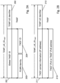
- Fig. 2A shows a first example for such a temporary identifier
- Fig. 2B shows a second example for such a temporary identifier, which are referred to hereinafter also a temporary identification for the UE, TEMP_UE_ID TNGF .
- the TNGF 25 generates the temporary identification for the UE, TEMP_UE_ID TNGF .
- the temporary identification for the UE, TEMP_UE_ID TNGF may instead be generated by the 5GC, e.g. the AMF 30.
- the AMF 30 may be configured to generate the temporary identification for the UE, TEMP_UE_ID TNGF , upon request from the TNGF, or when it receives a registration request of the UE via the TNGF 25 comprising the anonymized subscriber identification, such as the anonymous SUCI.
- the temporary identification for the UE, TEMP_UE_ID TNGF , generated by TNGF comprises two parts, i.e. a global TNGF node ID 201 and a temporary UE identifier 202.
- the global TNGF node ID 201 comprises, for example, a PLMN identity 203 and a TNGF ID 204, both of which are fixed values.
- the temporary UE identifier 202 can be a randomly generated number or a number which is pre-selected by the TNGF.
- the target of the temporary UE identifier 202 is to make the temporary identification for the UE, TEMP_UE_ID TNGF , unique.
- the temporary identification for the UE, TEMP_UE_ID TNGF , generated by TNGF may alternatively comprise, for example, a TNGF contact information 211, such as an IP address of the TNGF like the TNGF IPv4 or IPv6 address 213, and a temporary UE identifier 212 which may be created in accordance with the temporary UE identifier 202.
- a TNGF contact information 211 such as an IP address of the TNGF like the TNGF IPv4 or IPv6 address 213, and a temporary UE identifier 212 which may be created in accordance with the temporary UE identifier 202.
- the temporary identification for the UE, TEMP_UE_ID TNGF , generated by TNGF may be a totally random number or any unique number generated by the TNGF. That is, the temporary identification for the UE, TEMP_UE_ID TNGF , generated by TNGF (or the AMF, as indicated above) may be another number or value allowing to provide a unique temporary identification for the UE, TEMP_UE_ID TNGF .
- a processing for a registration procedure of a UE to a first communication network, such as a 3GPP based network, via a second communication network, such as a trusted non-3GPP network is described by using signaling diagrams illustrating the processing conducted for obtaining and forwarding the temporary identification for the UE, TEMP_UE_ID TNGF , when the user equipment uses an anonymized subscriber information, such as an anonymous SUCI, in the initial registration.
- an anonymized subscriber information such as an anonymous SUCI
- Figs. 3 and 4 show a signaling diagram illustrating an example of a procedure for controlling an access of a UE to a first communication network via a second communication network being different to the first communication network according to examples of embodiments.
- Figs. 3 and 4 describe a first example of a processing for registering a UE to a first communication network (e.g., 5G network) via a second communication network (e.g. SNPN network, TNAN) which enables that the UE suitably access also when an anonymized subscriber identification is used.
- a first communication network e.g., 5G network
- a second communication network e.g. SNPN network, TNAN
- the UE 10 connects to a trusted non-3GPP Access Network (e.g. TNAN 20 of Fig. 1 ) and it also registers to 5GC (e.g., AMF 30) via this TNAN 20.
- a trusted non-3GPP Access Network e.g. TNAN 20 of Fig. 1
- 5GC e.g., AMF 30
- EAP-based procedure may be used as a part of 5GC registration procedure.
- the link between the UE 10 and the TNAN can be any data link (L2) that supports e.g., EAP encapsulation, e.g. PPP, Ethernet, IEEE 802.11, etc.
- the interface between the TNAP and TNGF is e.g. an AAA (authentication, authorization and accounting) interface.
- the UE selects a PLMN and a TNAN for connecting to this PLMN by using a trusted non-3GPP access network selection procedure.
- the UE discovers the PLMNs with which the TNAN supports trusted connectivity (e.g. "5G connectivity").
- a layer-2 (L2) connection is established between the UE and the TNAP 23-1. This corresponds e.g. to an 802.11 association, or a PPP LCP negotiation.
- EAP authentication procedure is initiated.
- EAP messages are encapsulated into L2 packets, for example.
- the UE provides an NAI that triggers the TNAP to send in S304 an AAA request to the TNGF. It is to be noted that between the TNAP and the TNGF the EAP packets are encapsulated into AAA messages.
- the TNGF responds with an AUTH response message which includes an EAP-Request/5G-Start packet.
- the EAP-Request/5G-Start packet informs the UE to initiate an EAP-5G session, i.e. to start sending NAS messages encapsulated within EAP-5G packets.
- the UE validates the TNGF certificate and confirms that the TNGF identity matches the selected TNGF.
- the UE sends an EAP-Response/5G-NAS packet that contains a registration request message containing UE security capabilities and the anonymous SUCI (i.e. the anonymized subscription identification) as the UE ID.
- the UE sends the 5G-GUTI instead of anonymous SUCI.
- the TNGF is not aware of the identity of the subscriber, but receives only an anonymous identifier which can be used by a plurality of devices, so that the TNGF does not know the identity of the user.
- the TGNF selects an AMF. Then , in S310, the TGNF forwards the registration request received from the UE to the AMF with an N2 message.
- an authentication process is conducted.
- the AMF sends a key request to the AUSF in S314.
- the AUSF may initiate an authentication procedure between the AMF and the UE, wherein the authentication packets are encapsulated within NAS authentication messages and the NAS authentication messages are carried in N2 signaling between the AMF and the TNGF, and then are encapsulated within EAP-5G/5G-NAS packets between the TGNF and the UE.
- the AUSF sends an anchor key which is used by the AMF to derive NAS security keys. Furthermore, the AUSF includes an EAP-Success indication. The UE also derives the required keys in S317.
- the AMF sends a security mode command (SMC) to the UE in order to activate NAS security.
- SMC security mode command
- This message is sent to the TGNF within an N2 message.
- the AMF encapsulates the EAP-Success received from the AUSF within the SMC message.
- the TGNF since the UE has provided, as the UE ID in S307 an anonymous identifier, the TGNF generates a temporary UE identifier (TEMP_UE_ID TNGF ), for example in accordance with the measures described in connection with Fig. 2A /B.
- a temporary UE identifier (TEMP_UE_ID TNGF )
- the TNGF forwards the NAS SMC to the UE within an EAP-Request/5G-NAS packet.
- the temporary UE identifier (TEMP_UE_ID TNGF ) is also forwarded to the UE.
- the UE completes the authentication and creates or activates an NAS security context based on the information in the NAS SMC.
- the UE responds to the NAS SMC received from the AMF and encapsulates the NAS SMC Complete in an EAP-5G response sent to the AMF in S405 and S406.
- a K TNGF is created in the UE and in the AMF after the successful authentication.
- the K TNGF is transferred from the AMF to the TNGF in S407 within an N2 initial context setup request.
- the TNGF generates a KTNAP transfers it to TNAP in S408 within an AAA message.
- the TNGF sends in S408 to the UE an EAP-Request/5G-Notification packet containing the "TNGF Contact Info", which includes the IP address of TNGF (forwarded in S409 to the UE).
- the TNGF After receiving an EAP-Response/5G-Notification packet from the UE (in S410 and S411), the TNGF sends in S412 the EAP-Success packet being forwarded to the UE in S413.
- a security establishment procedure is executed wherein a common TNAP key is used by the UE and TNAP to derive security keys according to the applied non-3GPP technology and to establish a security association to protect all subsequent traffic. All messages between UE and TNAP are encrypted and integrity protected from this step onwards.
- the UE receives IP configuration information from the TNAN.
- the UE initiates an IKE_INIT exchange with the TNGF.
- the UE has received the IP address of TNGF during the EAP-5G signaling in S402, S403.
- the UE initiates an IKE_AUTH exchange in S418, wherein it includes in S417, when the UE has received the temporary identification for the UE, TEMP_UE_ID TNGF , this temporary identification for the UE, TEMP_UE_ID TNGF , as the UE ID (as indicated above, in case a 5G-GUTI is present, this would be used as in the UE Id provided in step S307).
- the UE when an anonymized subscriber identification is used by the UE, such as an anonymous SUCI, and the temporary identification for the UE has been provided by the network, the UE does not use in S417 and S418 the former (anonymous) user ID as in S307.
- the TNGF can link the now used user ID and can use it to identify the correct key for the mutual authentication.
- an IPsec security association is established between the UE and the TNGF and is used to transfer all subsequent NAS messages.
- the TNGF responds to the AMF with an N2 Initial Context Setup Response message.
- NAS registration accept message is sent by the AMF and is forwarded to the UE via the established connection.
- a PDU session establishment initiated by the UE is conducted. Then, user plane data for the established PDU session can be transported between the UE and TNGF.
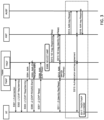
- Fig. 5 a signaling diagram illustrating another example of a procedure for controlling an access of a UE to a first communication network via a second communication network being different to the first communication network according to examples of embodiments is described.
- Fig. 5 is related to a processing which is an alternative to the processing described in Fig. 4 , i.e. it follows the processing described in connection with Fig. 3 .
- the UE sends an EAP-Response/5G-NAS packet that contains a registration request message containing UE security capabilities and the anonymous SUCI (i.e. the anonymized subscription identification) as the UE ID.
- the TGNF forwards the registration request received from the UE to the AMF with an N2 message, which includes the anonymous SUCI (i.e. the anonymized subscription identification) as the UE ID.
- the AMF generates the TNGF UE temporary ID for the UE in S501. That is, in the present example, the AMF generates a temporary UE identifier (TEMP_UE_ID TNGF ), for example in accordance with the measures described in connection with Fig. 2A /B.
- a temporary UE identifier (TEMP_UE_ID TNGF )
- the generation of the temporary UE identifier (TEMP_UE_ID TNGF ) is triggered by a request from the TNGF requesting the AMF to generate temporary UE identifier (TEMP_UE_ID TNGF ).
- the generation of the temporary UE identifier (TEMP_UE_ID TNGF ) is conducted only when required, depending on the information received from the UE.
- the AMF generates the temporary UE identifier (TEMP_UE_ID TNGF ) when a registration request with an anonymized subscription identification is received, for example.
- the AMF provides the generated temporary UE identifier (TEMP_UE_ID TNGF ) in S502, in which the AMF sends a security mode command (SMC) to the UE in order to activate NAS security. That is, the AMF provides the generated temporary UE identifier (TEMP_UE_ID TNGF ), for example, as part of NAS payload towards the UE. As an example for a secured signaling, the SMC request is used, which is integrity protected.
- SMC security mode command
- the TNGF forwards the NAS SMC to the UE within an EAP-Request/5G-NAS packet.
- the temporary UE identifier (TEMP_UE_ID TNGF ) received from the AMF is also forwarded to the UE.
- S505 to S507 correspond basically to S404 to S406 of Fig. 4 .
- the AMF transfers to the TNGF the K TNGF within an N2 initial context setup request.
- the AMF includes also the generated temporary UE identifier (TEMP_UE_ID TNGF ).
- the TNGF After receiving the TNGF key from AMF in S508, the TNGF sends in S509 to the UE (via S510) an EAP-Request/5G-Notification packet containing the "TNGF Contact Info", which includes the IP address of TNGF and optionally the temporary UE identifier (TEMP_UE_ID TNGF ).
- the further processing according to S511 to S519 corresponds to the processing according to S410 to S418 in Fig. 4 , including the usage of the temporary UE identifier (TEMP_UE_ID TNGF ) by the UE in S518 and S519.
- the further processing according to S419 to S422 in Fig. 4 can also be added to Fig. 5 .
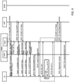
- Fig. 6 shows a signaling diagram illustrating an example of a procedure for controlling an access of a UE to a first communication network via a second communication network being different to the first communication network according to a further example of an embodiment.
- Fig. 6 describes an example of a mobility scenario. That is, when a UE switches connection from a source access point of the non-3GPP network, such as a source TNAP#1, to another access point representing a target TNAP#2 of the same TNGF, the UE connects to the target TNAP#2 by using the temporary UE identifier (TEMP_UE_ID TNGF ) assigned by the TNGF or the AMF as the UE ID. That is, instead of using the uses anonymous SUCI or the like, the UE connects to the new TNAP#2 by using the temporary UE identifier (TEMP_UE_ID TNGF ).
- TEMP_UE_ID TNGF temporary UE identifier
- the TNGF is able to identify and correlate the session of the UE already stored for the UE via the former (source) TNAP#1.
- the temporary UE identifier (TEMP_UE_ID TNGF ) assigned by TNGF or AMF is used during initial steps for TNGF to identify the UE.
- the TNGF stores the temporary UE identifier (TEMP_UE_ID TNGF ) assigned to a UE in UE context data in the TNGF for further communications.
- the UE is connected to the TNAN via TNAP#1, wherein the network (TNGF or AMF) assigns to the UE the temporary UE identifier (TEMP_UE_ID TNGF ).
- the temporary UE identifier (TEMP_UE_ID TNGF ) is stored, for example, in UE context data in the TNGF.
- TNAP mobility is started so that the UE connects from the TNAP#1 representing a source TNAP to a target TNAP (TNAP#2).
- the UE provides to the TNAP#2 the temporary UE identifier (TEMP_UE_ID TNGF ) being assigned for the session via TNAP#1.
- the target TNAP i.e. TNAP#2 sends the temporary UE identifier (TEMP_UE_ID TNGF ) received from the UE to the TNGF as information related to the TNAP mobility procedure.
- the temporary UE identifier (TEMP_UE_ID TNGF ) received from the UE to the TNGF as information related to the TNAP mobility procedure.
- the TNGF uses the received information, i.e. the temporary UE identifier (TEMP_UE_ID TNGF ), for correlating the session(s) of the UE between the former (source) TNAP#1 and the present (target) TNAP#2.
- the temporary UE identifier i.e. the temporary UE identifier (TEMP_UE_ID TNGF )
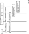
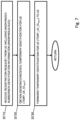
- Fig. 7 shows a flow chart of a processing conducted in a network node, such as a communication network control element or communication network control function, such as a TNGF, according to some examples of the disclosure. That is, Fig. 7 shows a flowchart related to a processing conducted by a network node, such as a communication network control element or communication network control function acting as gateway entity of a second communication network providing access to a first communication network, such as the TNGF 25 of Figs. 1 to 6 .
- the first communication network is, for example, a cellular communication network based on 3GPP specification
- the second communication network is for example a trusted non-3GPP access communication network, such as a SNPN.
- the TNGF receives a registration request of a UE for a registration to the first communication network via the second communication network.
- the UE uses in the registration request an anonymized subscriber identification element.
- a temporary identification for the UE is obtained, for example the TEMP_UE_ID TNGF described above.
- the temporary identification for the UE is obtained by generating the temporary identification for the UE in the TNGF.
- at least one of the following is used as a one part of the temporary identification for the UE: an identification element of a network node, such as the communication network control element or communication network control function acting as the gateway entity of the second communication network (for example a global TNGF ID, which includes a PLMN identity and a TNGF ID, for example), a contact information of a network node, such as the communication network control element or communication network control function acting as the gateway entity of the second communication network (for example, an IP address of the TNGF), or a random number.
- a pre-selected number is used as a pre-selected number, or a randomly generated number is used.
- the TNGF obtains the temporary identification for the UE by receiving a temporary identification for the UE from a network node, such as a communication network control element or communication network control function of the first communication network (e.g. the AMF).
- the temporary identification for the UE is received, for example, after forwarding the registration request of the UE to a network node, such as the communication network control element or communication network control function of the first communication network (AMF), wherein the registration request contains the anonymized subscriber identification element as the UE ID, for example.
- the temporary identification for the UE is received in response to a request sent from the TNGF to a network node, such as the communication network control element or communication network control function of the first communication network (e.g. the AMF).
- the request informs the AMF to provide the TNGF with the temporary identification for the UE.
- the temporary identification for the UE may also be added to TNGF contact information sent to the UE.
- the temporary identification for the UE is sent to the UE.
- the temporary identification for the UE is sent to the UE in a secured signaling message, such as a security mode command related message.
- the TNGF conducts a key exchange procedure with the UE wherein the temporary identification for the UE is used as an identification element of the UE in the corresponding signaling.
- the temporary identification for the UE is stored in UE context information in the TNGF.
- the TNGF receives, from a second access point (i.e. target access point in the mobility procedure) of the second communication network the temporary identification for the UE having been connected to a first access point (i.e. source access point in the mobility procedure) of the second communication network. Then, the TNGF correlates a communication session to the UE via the second access point by using the temporary identification for the UE when receiving a message from the UE including the temporary identification for the UE.
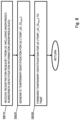
- Fig. 8 shows a flow chart of a processing conducted in a network node, such as a communication network control element or communication network control function, such as an AMF, according to some examples of the disclosure. That is, Fig. 8 shows a flowchart related to a processing conducted by a network node, such as a communication network control element or communication network control function acting as an access management entity of a first communication network, such as the AMF 30 of Figs. 1 to 6 .
- the first communication network is, for example, a cellular communication network based on 3GPP specification
- the second communication network is for example a trusted non-3GPP access communication network, such as a SNPN.
- the AMF receives, from a gateway entity of a second communication network providing access to the first communication network (e.g. the TNGF), a registration request of a UE for a registration to the first communication network via the second communication network.
- the registration request comprises an anonymized subscriber identification element as the UE ID.
- the AMF generates a temporary identification for the UE.
- the temporary identification for the UE is generated as described in the following. At least one of the following is used as a one part of the temporary identification for the UE: an identification element of a network node, such as the communication network control element or communication network control function acting as the gateway entity of the second communication network (for example a global TNGF ID, which includes a PLMN identity and a TNGF ID, for example), a contact information of a network node, such as the communication network control element or communication network control function acting as the gateway entity of the second communication network (for example, an IP address of the TNGF), or a random number.
- a pre-selected number is used as a pre-selected number, or a randomly generated number is used.
- the AMF receives from the gateway entity a request for providing the temporary identification for the UE when the registration request of the UE is received.
- the temporary identification for the UE is generated and forwarded in response to the request.
- the AMF forwards the temporary identification for the UE to the gateway entity of the second communication network (e.g. the TNGF).
- the temporary identification for the UE is sent to the gateway entity in a secured signaling message, such as a security mode command related message.
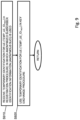
- Fig. 9 shows a flow chart of a processing conducted in a UE according to some examples of the disclosure. That is, Fig. 9 shows a flowchart related to a processing conducted by a UE connecting to a first communication network via a second communication network being different to the first communication network, such as the UE 10 of Figs. 1 to 6 .
- the first communication network is, for example, a cellular communication network based on 3GPP specification
- the second communication network is for example a trusted non-3GPP access communication network, such as a SNPN.
- the UE receives, in a registration procedure to the first communication network via the second communication network, wherein an anonymized subscriber identification element is used for the registration request, a temporary identification for the UE.
- the temporary identification for the UE is received in a secured signaling message, such as a security mode command related message.
- the temporary identification for the UE is also received in TNGF contact information.
- the UE uses the temporary identification for the UE in a key exchange procedure with a gateway entity of the second communication network (e.g. the TNGF) as an identification of the UE.
- a gateway entity of the second communication network e.g. the TNGF
- the UE when the UE conducts an access point mobility procedure for changing connection from a first access point (i.e. source access point in the mobility procedure) to a second access point (i.e. target access point in the mobility procedure) of the second communication network, the UE sends to the second access point (i.e. target access point in the mobility procedure) the temporary identification for the UE having been used with the first access point (i.e. source access point in the mobility procedure) as an identification of the UE.
- the second access point i.e. target access point in the mobility procedure
- the temporary identification for the UE having been used with the first access point (i.e. source access point in the mobility procedure) as an identification of the UE.
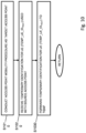
- Fig. 10 shows a flow chart of a processing conducted in a network node, such as a communication network element or communication network function acting as a second access point (i.e. a target access point in a mobility scenario) of the second communication network providing access to the second communication network, as a TNAP (TNAP#2), according to some examples of the disclosure. That is, Fig. 10 shows a flowchart related to a processing conducted by a TNAP, such as the TNAP#2 of Fig. 6 .
- a first communication network is, for example, a cellular communication network based on 3GPP specification
- the second communication network is for example a trusted non-3GPP access communication network, such as a SNPN.
- a UE when a UE conducts (in S1010) an access point mobility procedure for changing connection from a first access point (i.e. source access point in the mobility procedure) to a second access point (i.e. target access point in the mobility procedure) of the second communication network, the UE sends to the second access point (i.e. target access point in the mobility procedure) the TNAP#2 receives in S1020 a temporary identification for the UE having been used with the first access point (i.e. source access point in the mobility procedure) as an identification of the UE.
- a temporary identification for the UE having been used with the first access point (i.e. source access point in the mobility procedure) as an identification of the UE.
- the TNAP#2 forwards the temporary identification for the UE to a gateway entity of the second communication network (e.g. the TNGF) as the identification of the UE.
- a gateway entity of the second communication network e.g. the TNGF
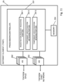
- Fig. 11 shows a diagram of a a network node, such as communication network control element or communication network control function of the second communication network (TNAN), such as the TNGF 25, which conducts a communication control according to some examples of embodiments, as described in connection with Figs. 2 to 6 .
- the network element or function such as the TNGF 25 may include further elements or functions besides those described herein below.
- the element or function may be also another device or function having a similar task, such as a chipset, a chip, a module, an application etc., which can also be part of a network element or attached as a separate element to a network element, or the like.
- each block and any combination thereof may be implemented by various means or their combinations, such as hardware, software, firmware, one or more processors and/or circuitry.
- the TNGF 25 shown in Fig. 11 may include a processing circuitry, a processing function, a control unit or a processor 251, such as a CPU or the like, which is suitable for executing instructions given by programs or the like related to the control procedure.
- the processor 251 may include one or more processing portions or functions dedicated to specific processing as described below, or the processing may be run in a single processor or processing function. Portions for executing such specific processing may be also provided as discrete elements or within one or more further processors, processing functions or processing portions, such as in one physical processor like a CPU or in one or more physical or virtual entities, for example.
- Reference signs 252 and 253 denotes input/output (I/O) units or functions (interfaces) connected to the processor or processing function 251.
- the I/O units 252 may be used for communicating with elements of the second communication network and thus with the UE 10 (e.g. via TNAP 23-1), as shown in Fig. 1 .
- the I/O units 253 may be used for communicating with elements of the first communication network, such as the AMF 30 as shown in Fig. 1 .
- the I/O units 252 and 253 may be combined units including communication equipment towards several entities, or may include a distributed structure with a plurality of different interfaces for different entities.
- Reference sign 254 denotes a memory usable, for example, for storing data and programs to be executed by the processor or processing function 251 and/or as a working storage of the processor or processing function 251. It is to be noted that the memory 254 may be implemented by using one or more memory portions of the same or different type of memory.
- the processor or processing function 251 is configured to execute processing related to the above described control procedure.
- the processor or processing circuitry or function 251 includes one or more of the following sub-portions.
- Sub-portion 2511 is a processing portion which is usable as a portion for receiving a registration request.
- the portion 2511 may be configured to perform processing according to S710 of Fig. 7 .
- the processor or processing circuitry or function 251 may include a sub-portion 2512 usable as a portion for obtaining a temporary identification.
- the portion 2512 may be configured to perform a processing according to S720 of Fig. 7 .
- the processor or processing circuitry or function 251 may include a sub-portion 2513 usable as a portion for sending the temporary identification.
- the portion 2513 may be configured to perform a processing according to S730 of Fig. 7 .
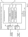
- Fig. 12 shows a diagram of a network node, such as a communication network control element or communication network control function, such as an AMF 30, which conducts a communication control according to some examples of embodiments, as described in connection with Figs. 2 to 6 .
- the network element or function such as the AMF 30 may include further elements or functions besides those described herein below.
- the element or function may be also another device or function having a similar task, such as a chipset, a chip, a module, an application etc., which can also be part of a network element or attached as a separate element to a network element, or the like.
- each block and any combination thereof may be implemented by various means or their combinations, such as hardware, software, firmware, one or more processors and/or circuitry.
- the AMF 30 shown in Fig. 12 may include a processing circuitry, a processing function, a control unit or a processor 301, such as a CPU or the like, which is suitable for executing instructions given by programs or the like related to the control procedure.
- the processor 301 may include one or more processing portions or functions dedicated to specific processing as described below, or the processing may be run in a single processor or processing function. Portions for executing such specific processing may be also provided as discrete elements or within one or more further processors, processing functions or processing portions, such as in one physical processor like a CPU or in one or more physical or virtual entities, for example.
- Reference signs 302 and 303 denotes input/output (I/O) units or functions (interfaces) connected to the processor or processing function 301.
- the I/O units 302 may be used for communicating with elements of a second communication network, such as the TNAN as shown in Fig. 1 .
- the I/O units 303 may be used for communicating with elements of a first communication network, such as the AUSF as shown in Fig. 1 .
- the I/O units 302 and 303 may be combined units including communication equipment towards several entities, or may include a distributed structure with a plurality of different interfaces for different entities.
- Reference sign 304 denotes a memory usable, for example, for storing data and programs to be executed by the processor or processing function 301 and/or as a working storage of the processor or processing function 301. It is to be noted that the memory 304 may be implemented by using one or more memory portions of the same or different type of memory.
- the processor or processing function 301 is configured to execute processing related to the above described control procedure.
- the processor or processing circuitry or function 301 includes one or more of the following sub-portions.
- Sub-portion 3011 is a processing portion which is usable as a portion for receiving a registration request. The portion 3011 may be configured to perform processing according to S810 of Fig. 8 .
- the processor or processing circuitry or function 301 may include a sub-portion 3012 usable as a portion for generating a temporary identification.
- the portion 3012 may be configured to perform a processing according to S820 of Fig. 8 .
- the processor or processing circuitry or function 301 may include a sub-portion 3013 usable as a portion for sending the temporary identification.
- the portion 3013 may be configured to perform a processing according to S830 of Fig. 8 .
- Fig. 13 shows a diagram of a user equipment (acting as a communication element or communication function), such as UE 10, which conducts a processing according to some examples of embodiments, as described in connection with Figs. 2 to 6 .
- the network element or function such as the UE 10 may include further elements or functions besides those described herein below.
- the element or function may be also another device or function having a similar task, such as a chipset, a chip, a module, an application etc., which can also be part of a network element or attached as a separate element to a network element, or the like.
- each block and any combination thereof may be implemented by various means or their combinations, such as hardware, software, firmware, one or more processors and/or circuitry.
- the UE 10 shown in Fig. 13 may include a processing circuitry, a processing function, a control unit or a processor 101, such as a CPU or the like, which is suitable for executing instructions given by programs or the like related to the control procedure.
- the processor 101 may include one or more processing portions or functions dedicated to specific processing as described below, or the processing may be run in a single processor or processing function. Portions for executing such specific processing may be also provided as discrete elements or within one or more further processors, processing functions or processing portions, such as in one physical processor like a CPU or in one or more physical or virtual entities, for example.
- Reference signs 102 and 103 denotes input/output (I/O) units or functions (interfaces) connected to the processor or processing function 101.
- the I/O units 102 may be used for communicating with elements of a second communication network, such as the TNAN as shown in Fig. 1 .
- the I/O units 103 may be used for communicating with elements of a first communication network, such as the AMF 30 as shown in Fig. 1 .
- the I/O units 102 and 103 may be combined units including communication equipment towards several entities, or may include a distributed structure with a plurality of different interfaces for different entities.
- Reference sign 104 denotes a memory usable, for example, for storing data and programs to be executed by the processor or processing function 101 and/or as a working storage of the processor or processing function 101. It is to be noted that the memory 104 may be implemented by using one or more memory portions of the same or different type of memory.
- the processor or processing function 101 is configured to execute processing related to the above described control procedure.
- the processor or processing circuitry or function 101 includes one or more of the following sub-portions.
- Sub-portion 1011 is a processing portion which is usable as a portion for receiving a temporary identification.
- the portion 1011 may be configured to perform processing according to S910 of Fig. 9 .
- the processor or processing circuitry or function 101 may include a sub-portion 1012 usable as a portion for using the temporary identification.
- the portion 1012 may be configured to perform a processing according to S920 of Fig. 9 .
- Fig. 14 shows a diagram of a network node, such as a communication network element or communication network function of the second communication network (TNAN), such as a TNAP being a target TNAP in case of a mobility procedure, which conducts a communication control according to some examples of embodiments, as described in connection with Fig. 6 .
- a network node such as a communication network element or communication network function of the second communication network (TNAN), such as a TNAP being a target TNAP in case of a mobility procedure, which conducts a communication control according to some examples of embodiments, as described in connection with Fig. 6 .
- the network element or function such as the TNAP 23 may include further elements or functions besides those described herein below.
- the element or function may be also another device or function having a similar task, such as a chipset, a chip, a module, an application etc., which can also be part of a network element or attached as a separate element to a network element, or the like. It should be understood that each block and any combination thereof may be implemented by various means or their combinations, such as hardware, software, firmware, one or more processors and/or circuitry.
- the TNAP 23 shown in Fig. 14 may include a processing circuitry, a processing function, a control unit or a processor 231, such as a CPU or the like, which is suitable for executing instructions given by programs or the like related to the control procedure.
- the processor 231 may include one or more processing portions or functions dedicated to specific processing as described below, or the processing may be run in a single processor or processing function. Portions for executing such specific processing may be also provided as discrete elements or within one or more further processors, processing functions or processing portions, such as in one physical processor like a CPU or in one or more physical or virtual entities, for example.
- Reference signs 232 and 233 denotes input/output (I/O) units or functions (interfaces) connected to the processor or processing function 231.
- the I/O units 232 may be used for communicating with the UE 10, as shown in Fig. 1 .
- the I/O units 233 may be used for communicating with elements of the second communication network, such as the TNGF 25 as shown in Fig. 1 .
- the I/O units 232 and 233 may be combined units including communication equipment towards several entities, or may include a distributed structure with a plurality of different interfaces for different entities.
- Reference sign 234 denotes a memory usable, for example, for storing data and programs to be executed by the processor or processing function 231 and/or as a working storage of the processor or processing function 231. It is to be noted that the memory 234 may be implemented by using one or more memory portions of the same or different type of memory.
- the processor or processing function 231 is configured to execute processing related to the above described control procedure.
- the processor or processing circuitry or function 231 includes one or more of the following sub-portions.
- Sub-portion 2311 is a processing portion which is usable as a portion for conducting an access point mobility procedure. The portion 2311 may be configured to perform processing according to S1010 of Fig. 10 .
- the processor or processing circuitry or function 231 may include a sub-portion 2312 usable as a portion for receiving a temporary identification.
- the portion 2312 may be configured to perform a processing according to S1020 of Fig. 10 .
- the processor or processing circuitry or function 231 may include a sub-portion 2313 usable as a portion for forwarding the temporary identification.
- the portion 2313 may be configured to perform a processing according to S1030 of Fig. 10 .
- an apparatus for a network node acting as a gateway entity of a second communication network providing access to a first communication network being different to the second communication network comprising means configured to receive a registration request of a user equipment for a registration to the first communication network via the second communication network, wherein the registration request comprises an anonymized subscriber identification element, means configured to obtain a temporary identification for the user equipment, and means configured to forward the temporary identification for the user equipment to the user equipment.
- the above defined apparatus may further comprise means for conducting at least one of the processing defined in the above described methods, for example a method according to that described in connection with Fig. 7 .
- an apparatus for a network node comprising means configured to receive, from a gateway entity of a second communication network providing access to the first communication network, the second communication network being different to the first communication network, a registration request of a user equipment for a registration to the first communication network via the second communication network, wherein the registration request comprises an anonymized subscriber identification element, means configured to generate a temporary identification for the user equipment, and means configured to forward the temporary identification for the user equipment to the gateway entity of the second communication network.
- the above defined apparatus may further comprise means for conducting at least one of the processing defined in the above described methods, for example a method according to that described in connection with Fig. 8 .
- an apparatus for a user equipment connecting to a first communication network via a second communication network being different to the first communication network comprising means configured to receive, in a registration procedure to the first communication network via the second communication network, wherein an anonymized subscriber identification element is used for the registration request, a temporary identification for the user equipment, and means configured to use the temporary identification for the user equipment in a key exchange procedure with a gateway entity of the second communication network as an identification of the user equipment.
- the above defined apparatus may further comprise means for conducting at least one of the processing defined in the above described methods, for example a method according to that described in connection with Fig. 9 .
- an apparatus for a network node acting as a second access point of a second communication network providing access to the second communication network comprising means configured to conduct an access point mobility procedure for changing connection of a user equipment connected to a first communication network being different to the second communication network via a first access point of the second communication network, wherein the second access point represents a target access point in the access point mobility procedure, means configured to receive a temporary identification for the user equipment having been used with the first access point as an identification of the user equipment, and means configured to forward the temporary identification for the user equipment to a gateway entity of the second communication network as the identification of the user equipment.
- the above defined apparatus may further comprise means for conducting at least one of the processing defined in the above described methods, for example a method according to that described in connection with Fig. 10 .
- a non-transitory computer readable medium comprising program instructions for causing an apparatus to perform, when used in a network node acting as a gateway entity of a second communication network providing access to a first communication network being different to the second communication network, a processing comprising receiving a registration request of a user equipment for a registration to the first communication network via the second communication network, wherein the registration request comprises an anonymized subscriber identification element, obtaining a temporary identification for the user equipment, and forwarding the temporary identification for the user equipment to the user equipment.
- a non-transitory computer readable medium comprising program instructions for causing an apparatus to perform, when used in a network node of a first communication network, a processing comprising receiving, from a gateway entity of a second communication network providing access to the first communication network, the second communication network being different to the first communication network, a registration request of a user equipment for a registration to the first communication network via the second communication network, wherein the registration request comprises an anonymized subscriber identification element, generating a temporary identification for the user equipment, and forwarding the temporary identification for the user equipment to the gateway entity of the second communication network.
- a non-transitory computer readable medium comprising program instructions for causing an apparatus to perform, when used in a user equipment connecting to a first communication network via a second communication network being different to the first communication network, a processing comprising receiving, in a registration procedure to the first communication network via the second communication network, wherein an anonymized subscriber identification element is used for the registration request, a temporary identification for the user equipment, and using the temporary identification for the user equipment in a key exchange procedure with a gateway entity of the second communication network as an identification of the user equipment.
- a non-transitory computer readable medium comprising program instructions for causing an apparatus to perform, when used in a network node acting as a second access point of a second communication network providing access to the second communication network, a processing comprising conducting an access point mobility procedure for changing connection of a user equipment connected to a first communication network being different to the second communication network via a first access point of the second communication network, wherein the second access point represents a target access point in the access point mobility procedure, receiving a temporary identification for the user equipment having been used with the first access point as an identification of the user equipment, and forwarding the temporary identification for the user equipment to a gateway entity of the second communication network as the identification of the user equipment.
Landscapes
- Engineering & Computer Science (AREA)
- Computer Networks & Wireless Communication (AREA)
- Signal Processing (AREA)
- Computer Security & Cryptography (AREA)
- Computer Hardware Design (AREA)
- Computing Systems (AREA)
- General Engineering & Computer Science (AREA)
- Databases & Information Systems (AREA)
- Mobile Radio Communication Systems (AREA)
Applications Claiming Priority (1)
| Application Number | Priority Date | Filing Date | Title |
|---|---|---|---|
| IN202241063102 | 2022-11-04 |
Publications (1)
| Publication Number | Publication Date |
|---|---|
| EP4366239A1 true EP4366239A1 (de) | 2024-05-08 |
Family
ID=88689542
Family Applications (1)
| Application Number | Title | Priority Date | Filing Date |
|---|---|---|---|
| EP23207367.6A Pending EP4366239A1 (de) | 2022-11-04 | 2023-11-02 | Anonyme registrierung mit einem kommunikationsnetzwerk |
Country Status (2)
| Country | Link |
|---|---|
| US (1) | US20240155533A1 (de) |
| EP (1) | EP4366239A1 (de) |
Families Citing this family (1)
| Publication number | Priority date | Publication date | Assignee | Title |
|---|---|---|---|---|
| US20240179577A1 (en) * | 2022-11-29 | 2024-05-30 | Sri International | Systems and Methods for Monitoring and Detection of Anomalous Activity in Software-Defined Radio Access Networks |
Citations (4)
| Publication number | Priority date | Publication date | Assignee | Title |
|---|---|---|---|---|
| US10999331B1 (en) * | 2016-07-06 | 2021-05-04 | Google Llc | Reverse discovery and pairing of client devices to a media device |
| WO2021165934A1 (en) * | 2020-02-20 | 2021-08-26 | Lenovo (Singapore) Pte. Ltd. | Re-authentication key generation |
| WO2022048743A1 (en) * | 2020-09-02 | 2022-03-10 | Lenovo (Singapore) Pte. Ltd. | Control-plane and user-plane trusted non-3gpp gateway function |
| US20220345307A1 (en) * | 2020-01-16 | 2022-10-27 | Zte Corporation | Method, Device, and System for Updating Anchor Key in a Communication Network for Encrypted Communication with Service Applications |
Family Cites Families (5)
| Publication number | Priority date | Publication date | Assignee | Title |
|---|---|---|---|---|
| CN118433706A (zh) * | 2018-08-09 | 2024-08-02 | 诺基亚技术有限公司 | 用于通过异构接入网络来安全实现连接的方法和装置 |
| EP4068858B1 (de) * | 2019-06-14 | 2023-12-13 | Ofinno, LLC | Verbindungshandhabung einer non-access stratum verbindung in ntn |
| US11160046B2 (en) * | 2019-11-27 | 2021-10-26 | Samsung Electronics Co., Ltd. | Method and a user equipment (UE) for accessing plurality of services on Wi-Fi simultaneously |
| US10820202B1 (en) * | 2019-12-17 | 2020-10-27 | Cisco Technology, Inc. | Identifying multiple sessions associated with a user equipment |
| BR112022022399A2 (pt) * | 2020-05-06 | 2022-12-13 | Lenovo Singapore Pte Ltd | Reautenticação de função de gateway |
-
2023
- 2023-11-02 EP EP23207367.6A patent/EP4366239A1/de active Pending
- 2023-11-04 US US18/502,000 patent/US20240155533A1/en active Pending
Patent Citations (4)
| Publication number | Priority date | Publication date | Assignee | Title |
|---|---|---|---|---|
| US10999331B1 (en) * | 2016-07-06 | 2021-05-04 | Google Llc | Reverse discovery and pairing of client devices to a media device |
| US20220345307A1 (en) * | 2020-01-16 | 2022-10-27 | Zte Corporation | Method, Device, and System for Updating Anchor Key in a Communication Network for Encrypted Communication with Service Applications |
| WO2021165934A1 (en) * | 2020-02-20 | 2021-08-26 | Lenovo (Singapore) Pte. Ltd. | Re-authentication key generation |
| WO2022048743A1 (en) * | 2020-09-02 | 2022-03-10 | Lenovo (Singapore) Pte. Ltd. | Control-plane and user-plane trusted non-3gpp gateway function |
Also Published As
| Publication number | Publication date |
|---|---|
| US20240155533A1 (en) | 2024-05-09 |
Similar Documents
| Publication | Publication Date | Title |
|---|---|---|
| US11818566B2 (en) | Unified authentication for integrated small cell and Wi-Fi networks | |
| JP6823047B2 (ja) | セルラーアクセスネットワークノードのための識別子を含むネットワークアクセス識別子 | |
| US10321503B2 (en) | Method and apparatus for attaching a remote unit to a mobile core network via a standalone untrusted non-3GPP access network | |
| JP5972290B2 (ja) | Epsにおけるモバイルルータ | |
| WO2018170617A1 (zh) | 一种基于非3gpp网络的入网认证方法、相关设备及系统 | |
| US11490252B2 (en) | Protecting WLCP message exchange between TWAG and UE | |
| US10299120B2 (en) | Methods and arrangements for identification of user equipments for authentication purposes | |
| TW201715864A (zh) | 用於網路切分的金鑰層級 | |
| US20200169885A1 (en) | Method and system for supporting security and information for proximity based service in mobile communication system environment | |
| WO2019122495A1 (en) | Authentication for wireless communications system | |
| CN112567812A (zh) | 用于移动设备的位置报告 | |
| EP4366239A1 (de) | Anonyme registrierung mit einem kommunikationsnetzwerk | |
| CN116867028A (zh) | 一种接入网设备的确定方法 | |
| CN118488437A (zh) | 通信方法及装置 | |
| HK1254125A1 (en) | Network access identifier including an identifier for a cellular access network node |
Legal Events
| Date | Code | Title | Description |
|---|---|---|---|
| PUAI | Public reference made under article 153(3) epc to a published international application that has entered the european phase |
Free format text: ORIGINAL CODE: 0009012 |
|
| STAA | Information on the status of an ep patent application or granted ep patent |
Free format text: STATUS: THE APPLICATION HAS BEEN PUBLISHED |
|
| AK | Designated contracting states |
Kind code of ref document: A1 Designated state(s): AL AT BE BG CH CY CZ DE DK EE ES FI FR GB GR HR HU IE IS IT LI LT LU LV MC ME MK MT NL NO PL PT RO RS SE SI SK SM TR |
|
| STAA | Information on the status of an ep patent application or granted ep patent |
Free format text: STATUS: REQUEST FOR EXAMINATION WAS MADE |
|
| 17P | Request for examination filed |
Effective date: 20241107 |
|
| RBV | Designated contracting states (corrected) |
Designated state(s): AL AT BE BG CH CY CZ DE DK EE ES FI FR GB GR HR HU IE IS IT LI LT LU LV MC ME MK MT NL NO PL PT RO RS SE SI SK SM TR |