EP3751635A1 - Battery pack including fixing member, device comprising same, and method for manufacturing battery pack - Google Patents
Battery pack including fixing member, device comprising same, and method for manufacturing battery pack Download PDFInfo
- Publication number
- EP3751635A1 EP3751635A1 EP19863853.8A EP19863853A EP3751635A1 EP 3751635 A1 EP3751635 A1 EP 3751635A1 EP 19863853 A EP19863853 A EP 19863853A EP 3751635 A1 EP3751635 A1 EP 3751635A1
- Authority
- EP
- European Patent Office
- Prior art keywords
- battery module
- bracket
- tray
- battery
- fixing member
- Prior art date
- Legal status (The legal status is an assumption and is not a legal conclusion. Google has not performed a legal analysis and makes no representation as to the accuracy of the status listed.)
- Granted
Links
Images


Classifications
-
- H—ELECTRICITY
- H01—ELECTRIC ELEMENTS
- H01M—PROCESSES OR MEANS, e.g. BATTERIES, FOR THE DIRECT CONVERSION OF CHEMICAL ENERGY INTO ELECTRICAL ENERGY
- H01M50/00—Constructional details or processes of manufacture of the non-active parts of electrochemical cells other than fuel cells, e.g. hybrid cells
- H01M50/20—Mountings; Secondary casings or frames; Racks, modules or packs; Suspension devices; Shock absorbers; Transport or carrying devices; Holders
-
- H—ELECTRICITY
- H01—ELECTRIC ELEMENTS
- H01M—PROCESSES OR MEANS, e.g. BATTERIES, FOR THE DIRECT CONVERSION OF CHEMICAL ENERGY INTO ELECTRICAL ENERGY
- H01M50/00—Constructional details or processes of manufacture of the non-active parts of electrochemical cells other than fuel cells, e.g. hybrid cells
- H01M50/20—Mountings; Secondary casings or frames; Racks, modules or packs; Suspension devices; Shock absorbers; Transport or carrying devices; Holders
- H01M50/244—Secondary casings; Racks; Suspension devices; Carrying devices; Holders characterised by their mounting method
-
- B—PERFORMING OPERATIONS; TRANSPORTING
- B60—VEHICLES IN GENERAL
- B60K—ARRANGEMENT OR MOUNTING OF PROPULSION UNITS OR OF TRANSMISSIONS IN VEHICLES; ARRANGEMENT OR MOUNTING OF PLURAL DIVERSE PRIME-MOVERS IN VEHICLES; AUXILIARY DRIVES FOR VEHICLES; INSTRUMENTATION OR DASHBOARDS FOR VEHICLES; ARRANGEMENTS IN CONNECTION WITH COOLING, AIR INTAKE, GAS EXHAUST OR FUEL SUPPLY OF PROPULSION UNITS IN VEHICLES
- B60K1/00—Arrangement or mounting of electrical propulsion units
- B60K1/04—Arrangement or mounting of electrical propulsion units of the electric storage means for propulsion
-
- H—ELECTRICITY
- H01—ELECTRIC ELEMENTS
- H01M—PROCESSES OR MEANS, e.g. BATTERIES, FOR THE DIRECT CONVERSION OF CHEMICAL ENERGY INTO ELECTRICAL ENERGY
- H01M50/00—Constructional details or processes of manufacture of the non-active parts of electrochemical cells other than fuel cells, e.g. hybrid cells
- H01M50/20—Mountings; Secondary casings or frames; Racks, modules or packs; Suspension devices; Shock absorbers; Transport or carrying devices; Holders
- H01M50/204—Racks, modules or packs for multiple batteries or multiple cells
- H01M50/207—Racks, modules or packs for multiple batteries or multiple cells characterised by their shape
- H01M50/209—Racks, modules or packs for multiple batteries or multiple cells characterised by their shape adapted for prismatic or rectangular cells
-
- H—ELECTRICITY
- H01—ELECTRIC ELEMENTS
- H01M—PROCESSES OR MEANS, e.g. BATTERIES, FOR THE DIRECT CONVERSION OF CHEMICAL ENERGY INTO ELECTRICAL ENERGY
- H01M50/00—Constructional details or processes of manufacture of the non-active parts of electrochemical cells other than fuel cells, e.g. hybrid cells
- H01M50/20—Mountings; Secondary casings or frames; Racks, modules or packs; Suspension devices; Shock absorbers; Transport or carrying devices; Holders
- H01M50/218—Mountings; Secondary casings or frames; Racks, modules or packs; Suspension devices; Shock absorbers; Transport or carrying devices; Holders characterised by the material
- H01M50/22—Mountings; Secondary casings or frames; Racks, modules or packs; Suspension devices; Shock absorbers; Transport or carrying devices; Holders characterised by the material of the casings or racks
- H01M50/222—Inorganic material
- H01M50/224—Metals
-
- H—ELECTRICITY
- H01—ELECTRIC ELEMENTS
- H01M—PROCESSES OR MEANS, e.g. BATTERIES, FOR THE DIRECT CONVERSION OF CHEMICAL ENERGY INTO ELECTRICAL ENERGY
- H01M50/00—Constructional details or processes of manufacture of the non-active parts of electrochemical cells other than fuel cells, e.g. hybrid cells
- H01M50/20—Mountings; Secondary casings or frames; Racks, modules or packs; Suspension devices; Shock absorbers; Transport or carrying devices; Holders
- H01M50/233—Mountings; Secondary casings or frames; Racks, modules or packs; Suspension devices; Shock absorbers; Transport or carrying devices; Holders characterised by physical properties of casings or racks, e.g. dimensions
- H01M50/238—Flexibility or foldability
-
- H—ELECTRICITY
- H01—ELECTRIC ELEMENTS
- H01M—PROCESSES OR MEANS, e.g. BATTERIES, FOR THE DIRECT CONVERSION OF CHEMICAL ENERGY INTO ELECTRICAL ENERGY
- H01M50/00—Constructional details or processes of manufacture of the non-active parts of electrochemical cells other than fuel cells, e.g. hybrid cells
- H01M50/20—Mountings; Secondary casings or frames; Racks, modules or packs; Suspension devices; Shock absorbers; Transport or carrying devices; Holders
- H01M50/233—Mountings; Secondary casings or frames; Racks, modules or packs; Suspension devices; Shock absorbers; Transport or carrying devices; Holders characterised by physical properties of casings or racks, e.g. dimensions
- H01M50/242—Mountings; Secondary casings or frames; Racks, modules or packs; Suspension devices; Shock absorbers; Transport or carrying devices; Holders characterised by physical properties of casings or racks, e.g. dimensions adapted for protecting batteries against vibrations, collision impact or swelling
-
- H—ELECTRICITY
- H01—ELECTRIC ELEMENTS
- H01M—PROCESSES OR MEANS, e.g. BATTERIES, FOR THE DIRECT CONVERSION OF CHEMICAL ENERGY INTO ELECTRICAL ENERGY
- H01M50/00—Constructional details or processes of manufacture of the non-active parts of electrochemical cells other than fuel cells, e.g. hybrid cells
- H01M50/20—Mountings; Secondary casings or frames; Racks, modules or packs; Suspension devices; Shock absorbers; Transport or carrying devices; Holders
- H01M50/262—Mountings; Secondary casings or frames; Racks, modules or packs; Suspension devices; Shock absorbers; Transport or carrying devices; Holders with fastening means, e.g. locks
- H01M50/264—Mountings; Secondary casings or frames; Racks, modules or packs; Suspension devices; Shock absorbers; Transport or carrying devices; Holders with fastening means, e.g. locks for cells or batteries, e.g. straps, tie rods or peripheral frames
-
- H—ELECTRICITY
- H01—ELECTRIC ELEMENTS
- H01M—PROCESSES OR MEANS, e.g. BATTERIES, FOR THE DIRECT CONVERSION OF CHEMICAL ENERGY INTO ELECTRICAL ENERGY
- H01M2220/00—Batteries for particular applications
- H01M2220/20—Batteries in motive systems, e.g. vehicle, ship, plane
-
- Y—GENERAL TAGGING OF NEW TECHNOLOGICAL DEVELOPMENTS; GENERAL TAGGING OF CROSS-SECTIONAL TECHNOLOGIES SPANNING OVER SEVERAL SECTIONS OF THE IPC; TECHNICAL SUBJECTS COVERED BY FORMER USPC CROSS-REFERENCE ART COLLECTIONS [XRACs] AND DIGESTS
- Y02—TECHNOLOGIES OR APPLICATIONS FOR MITIGATION OR ADAPTATION AGAINST CLIMATE CHANGE
- Y02E—REDUCTION OF GREENHOUSE GAS [GHG] EMISSIONS, RELATED TO ENERGY GENERATION, TRANSMISSION OR DISTRIBUTION
- Y02E60/00—Enabling technologies; Technologies with a potential or indirect contribution to GHG emissions mitigation
- Y02E60/10—Energy storage using batteries
Definitions
- the present invention relates to a battery package, a device including the same, and a manufacturing method of a battery package, and in detail, to a battery package battery including a fixing member to increase a fixing force when fixing a battery module in a package, a device including the same, and a manufacturing method of a battery package.
- a secondary battery capable of being charged and discharged is used as a power source of an electric vehicle (EV), a hybrid electric vehicle (HEV), and a plug-in hybrid electric vehicle (P-HEV) as a method for solving air pollution of conventional gasoline vehicles using a fossil fuel, a necessity for the development of the secondary battery is increasing.
- EV electric vehicle
- HEV hybrid electric vehicle
- P-HEV plug-in hybrid electric vehicle
- a secondary battery used in small devices two or three battery cells are arranged, and in the case of a secondary battery used in a medium and large device such as automobiles, a battery module in which a plurality of battery cells are electrically connected is used.
- a secondary battery having a large capacity while having a small size and a low weight and accordingly, rectangular batteries, pouch-type batteries, and the like, which are integrated with high integration and have a small weight to capacity, are mainly used.
- a plurality of battery cells are electrically connected in series, and in this case, stability of the secondary battery itself varies depending on a method of connecting and fixing a plurality of battery cells.
- a method of fixing the battery module inside the battery pack a method of directly fixing the battery module by using a bolt after stacking a plurality of battery cells is mainly used.
- FIG. 1 is a diagram illustrating a battery module fixing structure using bolts as a conventionally used method.
- FIG. 1 there is a method of using a bolt as the conventional fixing method of the battery module, and in this case, the bolt is fastened to the side surface of the lower part of the battery module to fix the battery module to a tray or a lower case of the battery pack.
- the thickness of the part to which the bolt is fastened which plays a role of fixing, is small, and the fixing force is low, there is a problem that it is difficult to match the dimensional safety in the fastening structure, and thus there is a problem that the stability of the battery module may not be maintained.
- Embodiments of the present invention have been proposed to solve the above problems of the conventionally proposed methods by providing a battery pack including a fixing member, a device including the same, and a manufacturing method of the battery pack for stably fixing the battery module against the vibration, impact, etc. applied to the battery module by processing the surface of the member for fixing the battery module to increase the fixing force.
- a battery package including a fixing member includes: a battery module including a plurality of battery cells; a tray disposed at the lower end of the battery module and receiving the battery module; and a bracket adjacent to one side of the tray and mounted and coupled to one side surface of the lower end of the battery module, wherein at least one of the surface of the bracket in contact with the battery module and the surface of the tray in contact with one side surface of the lower end of the battery module and disposed adjacent to the bracket has a wedge shape.
- Rigidity of the bracket and the tray may be higher than rigidity of the battery module.
- the bracket may be formed of a type of steel.
- the tray may be formed of a type of steel.
- the bracket may be a hold-down bracket.
- an upper case disposed at the upper end of the battery module and enclosing the battery module may be further included.
- a concave shape may be formed along the processed shape of the bracket and the tray at the surface of the battery module in contact with the surface part of the wedge shape of the bracket and the tray.
- a battery package manufacturing method may include, in the battery package including a battery module, a tray disposed at the lower end of the battery module and receiving the battery module, and a bracket adjacent to one side of the tray and mounted and coupled to one side surface of the lower end of the battery module: a step of processing at least one of the surface of the bracket and the surface of the tray to form a wedge shape; and a step of disposing the processed part of the bracket and the tray to be adjacent to one side surface of the lower end of the battery module and pressing toward the battery module.
- a step of forming a concave shape according to the processed shape of the bracket and the tray in the surface of the battery module in contact with the processed surface part of the bracket and the tray may be further included.
- Rigidity of the bracket and the tray may be higher than the rigidity of the battery module.
- the bracket may be formed of a type of steel.
- the tray may be formed of a type of steel.
- a fixing force of the battery module may be increased, and the battery module may be stably fixed against vibrations and impacts.
- the area of the portion that serves to fix the battery module is increased to enhance the fixing force, and the surface of the widened area is processed in order to prevent the battery module from shaking and falling off against the vibration and impact in all directions toward the battery module to increase the frictional force. This is described in more detail through FIG. 2 to FIG. 5 below.
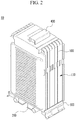
- FIG. 2 is a view showing a battery package including a fixing member according to an exemplary embodiment of the present invention.
- FIG. 2 shows a shape in which a tray 200 and a bracket 300 as a part of a configuration of a battery package 10 are coupled to a battery module 110
- the battery package 10 including the fixing member may include the battery module 110 including a plurality of battery cells 100, the tray 200 disposed at the lower end of the battery module 110 and receiving the battery module 110, and the bracket 300 adjacent to one side of the tray 200 and mounted and coupled to the one side surface of the lower end of the battery module 110.
- the battery module 110 may further include an upper case 400 disposed at the upper end of the battery module 110 and surrounding the battery module 110, the bracket 300 may be a hold-down bracket, and the battery cells 100 as plate-shaped battery cells may be connected in a series manner.
- At least one of the surface of the bracket 300 in contact with the battery module 110 and the surface of the tray 200 in contact with one side surface of the lower end of the battery module 110 and disposed adjacent to the bracket 300 is processed, and when the bracket 300 and the tray 200 are coupled to the battery module 110 to fix the battery module 110, a friction force is generated in the processed portion by pressure, thereby it is a feature of the present invention to be able to enhance the mutual fixing force.
- FIG. 3 is a view showing a cross-section of a battery package including a fixing member according to an exemplary embodiment of the present invention.
- FIG. 3 is the view illustrating a state in which the bracket 300 and the tray 200 are pressed and fixed to the battery module 110, when the bracket 300 and the tray 200 are pressed, it may be confirmed that the concave shape is formed according to the processed shape of the bracket 300 and the tray 200, that is, the wedge shape on the surface of the battery module 110 in contact with the wedge-shaped surface portion of the bracket 300 and the tray 200.
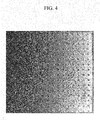
- FIG. 4 is a view to explain a shape of a processed surface in a battery package including a fixing member according to an exemplary embodiment of the present invention.
- FIG. 4 shows the wedge shape formed on the surface of the bracket 300 or the tray 200, and a plurality of wedge shapes as shown in FIG. 4 may be formed on the processed surface of the bracket 300 and the tray 200 in the present invention. That is, the surface of the bracket 300 and the tray 200 may include the shape such as a wedge grip. However, the shape of the processed surface of the bracket 300 and the tray 200 is not limited to this, and may be any shape that may increase the friction force in the contact surface.
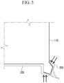
- FIG. 5 is a view to explain a pressure applied to a bracket in a battery package including a fixing member according to an exemplary embodiment of the present invention.
- the bracket 300 and the tray 200 are respectively mounted to the side surface and the lower surface at one side surface of the lower end of the battery module 110, as shown in FIG. 5 , and as the surface where the battery module 110 and the bracket 300 are in contact and the surface where the tray 200 of the position adjacent to the bracket 300 is in contact with the lower part of the battery module 110, a protrusion is formed at each surface of the bracket 300 and the tray 200, and the pressure may be applied from the outside for each surface.
- the pressure by applying the pressure to the battery module 110 in a direction perpendicular to the surface of the bracket 300 and the tray 200 of which the surface is processed in this way, it is possible to increase the fixing force to the battery module 110.
- the bracket 300 and the tray 200 are made of a type of steel, and the outer surface of the battery module 110 including the battery cells may be formed of a plastic, and in this case, the rigidity of the bracket 300 and the tray 200 becomes higher than the rigidity on the surface of the battery module 110.
- the pressure as shown in FIG. 5 while the processed wedge shape of the surface of the bracket 300 and the surface of the tray 200 having high rigidity presses the surface of the battery module 110 having relatively low rigidity, the surface as shown in FIG. 4 is engraved in the surface of the battery module 110.
- the manufacturing method of the battery package according to an exemplary embodiment of the present invention in the battery package including the battery module, the tray disposed at the lower end of the battery module and receiving the battery module and the bracket adjacent to one side of the tray and mounted and coupled to one side surface of the lower end of the battery module, may include a step S100 of processing at least one of the surface of the bracket and the surface of the tray to form the wedge shape and a step S200 of disposing the processed part of the bracket and the tray to be adjacent to one side surface of the lower end of the battery module and pressing it toward the battery module.
- a step S300 of forming a concave shape according to the processed shape of the bracket and the tray in the surface of the battery module in contact with the processed surface portion of the bracket and the tray may be further included.
- the rigidity of the bracket 300 and the tray 200 may include a fixing member that is higher in rigidity than the rigidity of the battery module 110, and according to an exemplary embodiment, the bracket 300 and the tray 200 may be formed of a type of steel, while the surface of the battery module 110 may be formed of a plastic material.
- a device may include a battery package 10, as a power source, including the battery module 110 including a plurality of battery cells 100, the tray 200 disposed at the lower end of the battery module 110 and receiving the battery module 110, and the bracket 300 adjacent to one side of the tray 200 and mounted and coupled to one side surface of the lower end of the battery module 110, wherein at least one of the surface of the bracket 300 in contact with the battery module 110 and the surface of the tray 200 in contact with one side surface of the lower end of the battery module 110 and disposed adjacent to the bracket 300 has the wedge shape.
- the device may be an electric vehicle, a hybrid electric vehicle, or a plug-in hybrid electric vehicle, but is not limited thereto.
- the present invention is the battery package including the fixing member, in order to solve a problem that the fixing force of the battery module is low and the battery module moves when receiving a load higher than a certain value in the conventional battery module fixing method using the bolt, and in addition, in the conventional method using a general bracket, in order to solve a problem that the stability of the battery module is inevitably low against the vibration, impact, etc. applied to the battery module, by processing the member fixing the battery module, it is meaningful in that the battery module may be stably fixed by increasing the fixing force of the battery module from the vibration and impact in all directions.
Landscapes
- Chemical & Material Sciences (AREA)
- Chemical Kinetics & Catalysis (AREA)
- Electrochemistry (AREA)
- General Chemical & Material Sciences (AREA)
- Inorganic Chemistry (AREA)
- Engineering & Computer Science (AREA)
- Combustion & Propulsion (AREA)
- Transportation (AREA)
- Mechanical Engineering (AREA)
- Battery Mounting, Suspending (AREA)
Abstract
Description
- The present application is a national phase entry under 35 U.S.C. § 371 of International Application No.
PCT/KR2019/010705, filed August 22, 2019 10-2018-0114408, filed on September 21, 2018 - The present invention relates to a battery package, a device including the same, and a manufacturing method of a battery package, and in detail, to a battery package battery including a fixing member to increase a fixing force when fixing a battery module in a package, a device including the same, and a manufacturing method of a battery package.
- In modern society, in accordance with the daily use of portable devices such as a mobile phone, a laptop computer, a camcorder, a digital camera, and the like, technologies of a field related to the portable devices have been actively developed. In addition, as a secondary battery capable of being charged and discharged is used as a power source of an electric vehicle (EV), a hybrid electric vehicle (HEV), and a plug-in hybrid electric vehicle (P-HEV) as a method for solving air pollution of conventional gasoline vehicles using a fossil fuel, a necessity for the development of the secondary battery is increasing.
- In the case of a secondary battery used in small devices, two or three battery cells are arranged, and in the case of a secondary battery used in a medium and large device such as automobiles, a battery module in which a plurality of battery cells are electrically connected is used.
- In order to increase efficiency of a device using the secondary battery, it is preferable to use a secondary battery having a large capacity while having a small size and a low weight, and accordingly, rectangular batteries, pouch-type batteries, and the like, which are integrated with high integration and have a small weight to capacity, are mainly used.
- In particular, in the case of a battery module used in a medium-large device, in order to provide capacity above a specific value required by the device, a plurality of battery cells are electrically connected in series, and in this case, stability of the secondary battery itself varies depending on a method of connecting and fixing a plurality of battery cells.
- In general, as a method of fixing the battery module inside the battery pack, a method of directly fixing the battery module by using a bolt after stacking a plurality of battery cells is mainly used.
-
FIG. 1 is a diagram illustrating a battery module fixing structure using bolts as a conventionally used method. - As shown in
FIG. 1 , there is a method of using a bolt as the conventional fixing method of the battery module, and in this case, the bolt is fastened to the side surface of the lower part of the battery module to fix the battery module to a tray or a lower case of the battery pack. However, since the thickness of the part to which the bolt is fastened, which plays a role of fixing, is small, and the fixing force is low, there is a problem that it is difficult to match the dimensional safety in the fastening structure, and thus there is a problem that the stability of the battery module may not be maintained. - When it is difficult to directly fix the battery module as shown in
FIG. 1 , there is a method fixing the battery module to the battery package by using a bracket. This is to arrange the battery module and the bracket to be overlapped, and to fix using the generated reaction force. - However, in the case of fixing using the conventional bracket, there is a problem that it is difficult to increase the fixing force of the battery module against vibration and impact applied to the battery module, the stability of the battery module is deteriorated when a load above a certain value is received.
- In the present invention, to improve the above problems, in the fixing of the battery module, it is necessary to develop the battery pack including a fixing member to increase stability, compared to the conventional battery module fixing method.
- Embodiments of the present invention have been proposed to solve the above problems of the conventionally proposed methods by providing a battery pack including a fixing member, a device including the same, and a manufacturing method of the battery pack for stably fixing the battery module against the vibration, impact, etc. applied to the battery module by processing the surface of the member for fixing the battery module to increase the fixing force.
- However, the problems to be solved by exemplary embodiments of the present invention are not limited to the problems described above, and may be variously expanded within the technical spirit of the present invention.
- A battery package including a fixing member according to a feature of the present invention includes: a battery module including a plurality of battery cells; a tray disposed at the lower end of the battery module and receiving the battery module; and a bracket adjacent to one side of the tray and mounted and coupled to one side surface of the lower end of the battery module, wherein at least one of the surface of the bracket in contact with the battery module and the surface of the tray in contact with one side surface of the lower end of the battery module and disposed adjacent to the bracket has a wedge shape.
- Rigidity of the bracket and the tray may be higher than rigidity of the battery module.
- The bracket may be formed of a type of steel.
- The tray may be formed of a type of steel.
- The bracket may be a hold-down bracket.
- In a state in which the battery module is mounted to the tray, an upper case disposed at the upper end of the battery module and enclosing the battery module may be further included.
- A concave shape may be formed along the processed shape of the bracket and the tray at the surface of the battery module in contact with the surface part of the wedge shape of the bracket and the tray.
- A battery package manufacturing method may include, in the battery package including a battery module, a tray disposed at the lower end of the battery module and receiving the battery module, and a bracket adjacent to one side of the tray and mounted and coupled to one side surface of the lower end of the battery module: a step of processing at least one of the surface of the bracket and the surface of the tray to form a wedge shape; and a step of disposing the processed part of the bracket and the tray to be adjacent to one side surface of the lower end of the battery module and pressing toward the battery module.
- A step of forming a concave shape according to the processed shape of the bracket and the tray in the surface of the battery module in contact with the processed surface part of the bracket and the tray may be further included.
- Rigidity of the bracket and the tray may be higher than the rigidity of the battery module.
- The bracket may be formed of a type of steel.
- The tray may be formed of a type of steel.
- Also, a device according to another aspect of the present invention for achieving the above objects may include a battery package, as a power source, including: a battery module including a plurality of battery cells; a tray disposed at a lower end of the battery module and receiving the battery module; and a bracket adjacent to one side of the tray and mounted and coupled to one side surface of the lower end of the battery module, wherein at least one of the surface of the bracket in contact with the battery module and the surface of the tray in contact with one side surface of the lower end of the battery module and disposed adjacent to the bracket has a wedge shape.
- According to exemplary embodiments of the present invention, by processing the surface of the fixing member used when fixing the battery module to increase a surface friction force between contact surfaces, a fixing force of the battery module may be increased, and the battery module may be stably fixed against vibrations and impacts.
-
-
FIG. 1 is a diagram showing a battery module fixing structure using a bolt as a conventionally used method. -
FIG. 2 is a view showing a battery package including a fixing member according to an exemplary embodiment of the present invention. -
FIG. 3 is a view showing a cross-section of a battery package including a fixing member according to an exemplary embodiment of the present invention. -
FIG. 4 is a view to explain a shape of a processed surface in a battery package including a fixing member according to an exemplary embodiment of the present invention. -
FIG. 5 is a view to explain a pressure applied to a bracket in a battery package including a fixing member according to an exemplary embodiment of the present invention. - The present invention will be described more fully hereinafter with reference to the accompanying drawings, in which exemplary embodiments of the invention are shown. As those skilled in the art would realize, the described embodiments may be modified in various different ways, all without departing from the spirit or scope of the present invention.
- In order to clearly explain the present invention, portions that are not directly related to the present invention are omitted, and the same reference numerals are attached to the same or similar constituent elements through the entire specification.
- In addition, the size and thickness of each configuration shown in the drawings are arbitrarily shown for better understanding and ease of description, but the present invention is not limited thereto. In the drawings, the thickness of layers, films, panels, regions, etc., are exaggerated for clarity. In the drawings, for better understanding and ease of description, the thicknesses of some layers and areas are exaggerated.
- It will be understood that when an element such as a layer, film, region, or substrate is referred to as being "on" another element, it can be directly on the other element or intervening elements may also be present. In contrast, when an element is referred to as being "directly on" another element, there are no intervening elements present. Further, in the specification, the word "on" or "above" means positioned on or below the object portion, and does not necessarily mean positioned on the upper side of the object portion based on a gravitational direction.
- In addition, unless explicitly described to the contrary, the word "comprise" and variations such as "comprises" or "comprising" will be understood to imply the inclusion of stated elements but not the exclusion of any other elements.
- In the present invention, in order to solve the problem in the conventional battery module fixing method, the area of the portion that serves to fix the battery module is increased to enhance the fixing force, and the surface of the widened area is processed in order to prevent the battery module from shaking and falling off against the vibration and impact in all directions toward the battery module to increase the frictional force. This is described in more detail through
FIG. 2 to FIG. 5 below. -
FIG. 2 is a view showing a battery package including a fixing member according to an exemplary embodiment of the present invention. -
FIG. 2 shows a shape in which atray 200 and abracket 300 as a part of a configuration of abattery package 10 are coupled to abattery module 110, and as shown inFIG. 2 , thebattery package 10 including the fixing member according to an exemplary embodiment of the present invention may include thebattery module 110 including a plurality ofbattery cells 100, thetray 200 disposed at the lower end of thebattery module 110 and receiving thebattery module 110, and thebracket 300 adjacent to one side of thetray 200 and mounted and coupled to the one side surface of the lower end of thebattery module 110. - In a state in which the
battery module 110 is mounted on thetray 200, thebattery module 110 may further include anupper case 400 disposed at the upper end of thebattery module 110 and surrounding thebattery module 110, thebracket 300 may be a hold-down bracket, and thebattery cells 100 as plate-shaped battery cells may be connected in a series manner. - Particularly, in the present invention, at least one of the surface of the
bracket 300 in contact with thebattery module 110 and the surface of thetray 200 in contact with one side surface of the lower end of thebattery module 110 and disposed adjacent to thebracket 300 is processed, and when thebracket 300 and thetray 200 are coupled to thebattery module 110 to fix thebattery module 110, a friction force is generated in the processed portion by pressure, thereby it is a feature of the present invention to be able to enhance the mutual fixing force. -
FIG. 3 is a view showing a cross-section of a battery package including a fixing member according to an exemplary embodiment of the present invention. - From the cross-sectional surface of the
battery pack 10 including the fixing member according to the present exemplary embodiment shown inFIG. 3 , it may be confirmed that the part of thetray 200 in contact with thebattery module 110 and the surface of thebracket 200 are processed and the processed part has a wedge shape. - Specifically,
FIG. 3 is the view illustrating a state in which thebracket 300 and thetray 200 are pressed and fixed to thebattery module 110, when thebracket 300 and thetray 200 are pressed, it may be confirmed that the concave shape is formed according to the processed shape of thebracket 300 and thetray 200, that is, the wedge shape on the surface of thebattery module 110 in contact with the wedge-shaped surface portion of thebracket 300 and thetray 200. -
FIG. 4 is a view to explain a shape of a processed surface in a battery package including a fixing member according to an exemplary embodiment of the present invention. - That is,
FIG. 4 shows the wedge shape formed on the surface of thebracket 300 or thetray 200, and a plurality of wedge shapes as shown inFIG. 4 may be formed on the processed surface of thebracket 300 and thetray 200 in the present invention. That is, the surface of thebracket 300 and thetray 200 may include the shape such as a wedge grip. However, the shape of the processed surface of thebracket 300 and thetray 200 is not limited to this, and may be any shape that may increase the friction force in the contact surface. -
FIG. 5 is a view to explain a pressure applied to a bracket in a battery package including a fixing member according to an exemplary embodiment of the present invention. - According to the present exemplary embodiment, the
bracket 300 and thetray 200 are respectively mounted to the side surface and the lower surface at one side surface of the lower end of thebattery module 110, as shown inFIG. 5 , and as the surface where thebattery module 110 and thebracket 300 are in contact and the surface where thetray 200 of the position adjacent to thebracket 300 is in contact with the lower part of thebattery module 110, a protrusion is formed at each surface of thebracket 300 and thetray 200, and the pressure may be applied from the outside for each surface. In the present invention, by applying the pressure to thebattery module 110 in a direction perpendicular to the surface of thebracket 300 and thetray 200 of which the surface is processed in this way, it is possible to increase the fixing force to thebattery module 110. - Specifically, the
bracket 300 and thetray 200 are made of a type of steel, and the outer surface of thebattery module 110 including the battery cells may be formed of a plastic, and in this case, the rigidity of thebracket 300 and thetray 200 becomes higher than the rigidity on the surface of thebattery module 110. Thus, by the pressure as shown inFIG. 5 , while the processed wedge shape of the surface of thebracket 300 and the surface of thetray 200 having high rigidity presses the surface of thebattery module 110 having relatively low rigidity, the surface as shown inFIG. 4 is engraved in the surface of thebattery module 110. - As such, while the protruding and recessed shapes are inscribed between the pressing and pressed components, slippage may be prevented between the components, and the frictional force is generated to enhance the fixing force. In particular, it is possible to maintain the high fixing force against the vibration and the impact applied in all directions, not just the vibration and the impact applied to the
battery module 110 in a specific direction. - The manufacturing method of the battery package according to an exemplary embodiment of the present invention, in the battery package including the battery module, the tray disposed at the lower end of the battery module and receiving the battery module and the bracket adjacent to one side of the tray and mounted and coupled to one side surface of the lower end of the battery module, may include a step S100 of processing at least one of the surface of the bracket and the surface of the tray to form the wedge shape and a step S200 of disposing the processed part of the bracket and the tray to be adjacent to one side surface of the lower end of the battery module and pressing it toward the battery module.
- According to an exemplary embodiment, a step S300 of forming a concave shape according to the processed shape of the bracket and the tray in the surface of the battery module in contact with the processed surface portion of the bracket and the tray may be further included.
- When mutually fixing the
bracket 300 and thetray 200 by pressing thebracket 300 and thetray 200 to thebattery module 110 to form the shape in thebattery module 110, the fixing force is strengthened by the mutual frictional force. In this case, the rigidity of thebracket 300 and thetray 200 may include a fixing member that is higher in rigidity than the rigidity of thebattery module 110, and according to an exemplary embodiment, thebracket 300 and thetray 200 may be formed of a type of steel, while the surface of thebattery module 110 may be formed of a plastic material. - Also, a device according to an exemplary embodiment of the present invention may include a
battery package 10, as a power source, including thebattery module 110 including a plurality ofbattery cells 100, thetray 200 disposed at the lower end of thebattery module 110 and receiving thebattery module 110, and thebracket 300 adjacent to one side of thetray 200 and mounted and coupled to one side surface of the lower end of thebattery module 110, wherein at least one of the surface of thebracket 300 in contact with thebattery module 110 and the surface of thetray 200 in contact with one side surface of the lower end of thebattery module 110 and disposed adjacent to thebracket 300 has the wedge shape. - The device may be an electric vehicle, a hybrid electric vehicle, or a plug-in hybrid electric vehicle, but is not limited thereto.
- As above-described, the present invention is the battery package including the fixing member, in order to solve a problem that the fixing force of the battery module is low and the battery module moves when receiving a load higher than a certain value in the conventional battery module fixing method using the bolt, and in addition, in the conventional method using a general bracket, in order to solve a problem that the stability of the battery module is inevitably low against the vibration, impact, etc. applied to the battery module, by processing the member fixing the battery module, it is meaningful in that the battery module may be stably fixed by increasing the fixing force of the battery module from the vibration and impact in all directions.
- While this invention has been described in connection with what is presently considered to be practical exemplary embodiments, it is to be understood that the invention is not limited to the disclosed embodiments. On the contrary, it is intended to cover various modifications and equivalent arrangements included within the spirit and scope of the appended claims.
-
- 10:
- battery package
- 100:
- battery cell
- 110:
- battery module
- 200:
- tray
- 300:
- bracket
- 400:
- upper case
Claims (13)
- A battery package including a fixing member comprising:a battery module including a plurality of battery cells;a tray disposed at the lower end of the battery module and receiving the battery module; anda bracket adjacent to one side of the tray and mounted and coupled to one side surface of the lower end of the battery module,wherein at least one of the surface of the bracket in contact with the battery module and the surface of the tray in contact with one side surface of the lower end of the battery module and disposed adjacent to the bracket has a wedge shape.
- The battery package including the fixing member of claim 1, wherein
rigidity of the bracket and the tray is higher than rigidity of the battery module. - The battery package including the fixing member of claim 2, wherein
the bracket is formed of a type of steel. - The battery package including the fixing member of claim 2, wherein
the tray is formed of a type of steel. - The battery package including the fixing member of claim 1, wherein
the bracket is a hold-down bracket. - The battery package including the fixing member of claim 1, further comprising,
in a state in which the battery module is mounted to the tray, an upper case disposed at the upper end of the battery module and enclosing the battery module. - The battery package including the fixing member of claim 1, wherein
a concave shape is formed along the processed shape of the bracket and the tray at the surface of the battery module in contact with the surface part of the wedge shape of the bracket and the tray. - A battery package manufacturing method comprising, in the battery package including a battery module, a tray disposed at the lower end of the battery module and receiving the battery module, and a bracket adjacent to one side of the tray and mounted and coupled to one side surface of the lower end of the battery module:a step of processing at least one of the surface of the bracket and the surface of the tray to form a wedge shape; anda step of disposing the processed part of the bracket and the tray to be adjacent to one side surface of the lower end of the battery module and pressing toward the battery module.
- The battery package manufacturing method of claim 8, further comprising
a step of forming a concave shape according to the processed shape of the bracket and the tray in the surface of the battery module in contact with the processed surface part of the bracket and the tray. - The battery package manufacturing method of claim 8, wherein
rigidity of the bracket and the tray is higher than rigidity of the battery module. - The battery package manufacturing method of claim 10, wherein
the bracket is formed of a type of steel. - The battery package manufacturing method of claim 10, wherein
the tray is formed of a type of steel. - A device comprising the battery package of claim 1 as a power source.
Applications Claiming Priority (2)
| Application Number | Priority Date | Filing Date | Title |
|---|---|---|---|
| KR1020180114408A KR102396436B1 (en) | 2018-09-21 | 2018-09-21 | Battery pack including fixing member, device including the same, and the battry pack manufacturing method |
| PCT/KR2019/010705 WO2020060047A1 (en) | 2018-09-21 | 2019-08-22 | Battery pack including fixing member, device comprising same, and method for manufacturing battery pack |
Publications (3)
| Publication Number | Publication Date |
|---|---|
| EP3751635A1 true EP3751635A1 (en) | 2020-12-16 |
| EP3751635A4 EP3751635A4 (en) | 2021-06-09 |
| EP3751635B1 EP3751635B1 (en) | 2024-11-20 |
Family
ID=69887460
Family Applications (1)
| Application Number | Title | Priority Date | Filing Date |
|---|---|---|---|
| EP19863853.8A Active EP3751635B1 (en) | 2018-09-21 | 2019-08-22 | Battery package including fixing member, a device including the same and manufacturing method of battery package |
Country Status (9)
| Country | Link |
|---|---|
| US (1) | US11509018B2 (en) |
| EP (1) | EP3751635B1 (en) |
| JP (1) | JP7258397B2 (en) |
| KR (1) | KR102396436B1 (en) |
| CN (1) | CN111771296B (en) |
| ES (1) | ES3000084T3 (en) |
| HU (1) | HUE069601T2 (en) |
| PL (1) | PL3751635T3 (en) |
| WO (1) | WO2020060047A1 (en) |
Cited By (1)
| Publication number | Priority date | Publication date | Assignee | Title |
|---|---|---|---|---|
| EP4181296A4 (en) * | 2021-01-13 | 2024-12-11 | LG Energy Solution, Ltd. | BATTERY PACK AND DEVICE COMPRISING SAME |
Families Citing this family (1)
| Publication number | Priority date | Publication date | Assignee | Title |
|---|---|---|---|---|
| DE102024204866A1 (en) | 2024-05-27 | 2025-11-27 | Robert Bosch Gesellschaft mit beschränkter Haftung | Battery pack |
Family Cites Families (20)
| Publication number | Priority date | Publication date | Assignee | Title |
|---|---|---|---|---|
| JP2002225570A (en) | 2001-01-30 | 2002-08-14 | Toyota Motor Corp | Battery fixing structure |
| JP2003237381A (en) * | 2002-02-20 | 2003-08-27 | Uchihama Kasei Kk | Fixing member and fixing structure |
| DE10314030B4 (en) | 2003-03-28 | 2005-07-14 | A. Raymond & Cie | Device for fastening a housing, in particular that of a motor vehicle battery, to a carrier |
| US8110300B2 (en) * | 2008-06-30 | 2012-02-07 | Lg Chem, Ltd. | Battery mounting system |
| JP5618747B2 (en) | 2010-10-06 | 2014-11-05 | アイシン軽金属株式会社 | Battery stack fixing structure |
| DE102011077330A1 (en) | 2011-06-10 | 2012-12-13 | Sb Limotive Company Ltd. | Battery, motor vehicle with this battery and method of mounting this battery |
| CN202174924U (en) * | 2011-07-29 | 2012-03-28 | 比亚迪股份有限公司 | Mounting structure of power cell of vehicle |
| JP5592341B2 (en) * | 2011-12-09 | 2014-09-17 | 本田技研工業株式会社 | Battery module unit |
| US8911892B2 (en) * | 2012-05-21 | 2014-12-16 | Lg Chem, Ltd. | Battery module mounting assembly and method for mounting a battery module to a base plate |
| US8592069B1 (en) * | 2012-10-15 | 2013-11-26 | GM Global Technology Operations LLC | Battery securement systems and apparatus |
| KR101425569B1 (en) * | 2013-02-25 | 2014-08-01 | 주식회사 피엠그로우 | Battery case |
| US9484562B2 (en) * | 2014-03-27 | 2016-11-01 | Ford Global Technologies, Llc | Traction battery assembly |
| KR101769577B1 (en) * | 2014-05-07 | 2017-08-18 | 주식회사 엘지화학 | Battery Pack Having Hold Down Bracket |
| JP2016184470A (en) | 2015-03-25 | 2016-10-20 | トヨタ自動車株式会社 | Battery pack |
| KR101712283B1 (en) * | 2015-08-31 | 2017-03-03 | 쌍용자동차 주식회사 | Battery tray for automobile |
| KR101794266B1 (en) * | 2016-01-07 | 2017-11-07 | 삼성에스디아이 주식회사 | Tray for battery module adapted for slide assembly |
| KR102123661B1 (en) * | 2016-02-22 | 2020-06-16 | 주식회사 엘지화학 | Battery pack and vehicle comprising the battery pack |
| KR101764057B1 (en) * | 2016-03-29 | 2017-08-01 | 쌍용자동차 주식회사 | plate battery tray assembly for automobile |
| JP2018049697A (en) | 2016-09-20 | 2018-03-29 | 株式会社豊田自動織機 | Battery pack |
| US11011790B2 (en) * | 2017-03-17 | 2021-05-18 | Ford Global Technologies, Llc | Traction battery pack plate with retention flange |
-
2018
- 2018-09-21 KR KR1020180114408A patent/KR102396436B1/en active Active
-
2019
- 2019-08-22 US US16/976,574 patent/US11509018B2/en active Active
- 2019-08-22 ES ES19863853T patent/ES3000084T3/en active Active
- 2019-08-22 HU HUE19863853A patent/HUE069601T2/en unknown
- 2019-08-22 WO PCT/KR2019/010705 patent/WO2020060047A1/en not_active Ceased
- 2019-08-22 JP JP2020544506A patent/JP7258397B2/en active Active
- 2019-08-22 PL PL19863853.8T patent/PL3751635T3/en unknown
- 2019-08-22 CN CN201980015544.6A patent/CN111771296B/en active Active
- 2019-08-22 EP EP19863853.8A patent/EP3751635B1/en active Active
Cited By (1)
| Publication number | Priority date | Publication date | Assignee | Title |
|---|---|---|---|---|
| EP4181296A4 (en) * | 2021-01-13 | 2024-12-11 | LG Energy Solution, Ltd. | BATTERY PACK AND DEVICE COMPRISING SAME |
Also Published As
| Publication number | Publication date |
|---|---|
| WO2020060047A1 (en) | 2020-03-26 |
| CN111771296B (en) | 2025-08-08 |
| US20210050567A1 (en) | 2021-02-18 |
| CN111771296A (en) | 2020-10-13 |
| KR102396436B1 (en) | 2022-05-09 |
| EP3751635A4 (en) | 2021-06-09 |
| US11509018B2 (en) | 2022-11-22 |
| EP3751635B1 (en) | 2024-11-20 |
| HUE069601T2 (en) | 2025-03-28 |
| PL3751635T3 (en) | 2025-02-10 |
| KR20200034520A (en) | 2020-03-31 |
| ES3000084T3 (en) | 2025-02-27 |
| JP7258397B2 (en) | 2023-04-17 |
| JP2021514536A (en) | 2021-06-10 |
Similar Documents
| Publication | Publication Date | Title |
|---|---|---|
| EP2624337B1 (en) | Battery module having enhanced safety | |
| US9425440B2 (en) | Compact battery cell having improved durability and battery pack comprising the same | |
| US12230819B2 (en) | Battery module and battery pack including the same | |
| EP4047720A1 (en) | Battery module and battery pack including same | |
| KR102214890B1 (en) | Load-bearing battery module for a motor vehicle and a motor vehicle | |
| EP3806180B1 (en) | Battery module | |
| EP3907811B1 (en) | Battery module and battery pack including the same | |
| US20130344380A1 (en) | Rechargeable battery | |
| US11509018B2 (en) | Battery package including fixing member, a device including the same and manufacturing method of battery package | |
| US12046731B2 (en) | Battery module, method for preparing the same and battery pack including the same | |
| EP4170798A1 (en) | Battery module and battery pack comprising same | |
| EP4266467B1 (en) | Battery module and battery pack including same | |
| CN114843687B (en) | Protection assembly and battery case including the same | |
| EP4142021B1 (en) | Battery module and battery pack including the same | |
| US11196122B2 (en) | Battery module and battery pack including the same | |
| EP4525158A1 (en) | Battery module | |
| KR20200061908A (en) | Battery pack, and device including the same | |
| EP4589707A1 (en) | Battery pack and method of manufacturing such | |
| EP4033594B1 (en) | Battery module with improved stacking structure, and battery pack comprising the same | |
| US20260011769A1 (en) | Battery Cell Fixing Apparatus | |
| KR102711277B1 (en) | Battery module, and battery pack including the same | |
| KR102349918B1 (en) | Battery module | |
| EP3813145A1 (en) | Battery pack and device including same | |
| KR20250011444A (en) | Battery pack and device including the same |
Legal Events
| Date | Code | Title | Description |
|---|---|---|---|
| STAA | Information on the status of an ep patent application or granted ep patent |
Free format text: STATUS: THE INTERNATIONAL PUBLICATION HAS BEEN MADE |
|
| PUAI | Public reference made under article 153(3) epc to a published international application that has entered the european phase |
Free format text: ORIGINAL CODE: 0009012 |
|
| STAA | Information on the status of an ep patent application or granted ep patent |
Free format text: STATUS: REQUEST FOR EXAMINATION WAS MADE |
|
| 17P | Request for examination filed |
Effective date: 20200910 |
|
| AK | Designated contracting states |
Kind code of ref document: A1 Designated state(s): AL AT BE BG CH CY CZ DE DK EE ES FI FR GB GR HR HU IE IS IT LI LT LU LV MC MK MT NL NO PL PT RO RS SE SI SK SM TR |
|
| AX | Request for extension of the european patent |
Extension state: BA ME |
|
| REG | Reference to a national code |
Ref country code: DE Ref legal event code: R079 Free format text: PREVIOUS MAIN CLASS: H01M0002100000 Ref country code: DE Ref legal event code: R079 Ref document number: 602019062379 Country of ref document: DE Free format text: PREVIOUS MAIN CLASS: H01M0002100000 Ipc: H01M0050224000 |
|
| A4 | Supplementary search report drawn up and despatched |
Effective date: 20210511 |
|
| RIC1 | Information provided on ipc code assigned before grant |
Ipc: H01M 50/224 20210101AFI20210505BHEP Ipc: H01M 50/238 20210101ALI20210505BHEP Ipc: H01M 50/242 20210101ALI20210505BHEP Ipc: H01M 50/264 20210101ALI20210505BHEP |
|
| DAV | Request for validation of the european patent (deleted) | ||
| DAX | Request for extension of the european patent (deleted) | ||
| RAP1 | Party data changed (applicant data changed or rights of an application transferred) |
Owner name: LG ENERGY SOLUTION LTD. |
|
| RAP3 | Party data changed (applicant data changed or rights of an application transferred) |
Owner name: LG ENERGY SOLUTION, LTD. |
|
| STAA | Information on the status of an ep patent application or granted ep patent |
Free format text: STATUS: EXAMINATION IS IN PROGRESS |
|
| 17Q | First examination report despatched |
Effective date: 20230104 |
|
| GRAP | Despatch of communication of intention to grant a patent |
Free format text: ORIGINAL CODE: EPIDOSNIGR1 |
|
| STAA | Information on the status of an ep patent application or granted ep patent |
Free format text: STATUS: GRANT OF PATENT IS INTENDED |
|
| INTG | Intention to grant announced |
Effective date: 20240906 |
|
| GRAS | Grant fee paid |
Free format text: ORIGINAL CODE: EPIDOSNIGR3 |
|
| GRAA | (expected) grant |
Free format text: ORIGINAL CODE: 0009210 |
|
| STAA | Information on the status of an ep patent application or granted ep patent |
Free format text: STATUS: THE PATENT HAS BEEN GRANTED |
|
| AK | Designated contracting states |
Kind code of ref document: B1 Designated state(s): AL AT BE BG CH CY CZ DE DK EE ES FI FR GB GR HR HU IE IS IT LI LT LU LV MC MK MT NL NO PL PT RO RS SE SI SK SM TR |
|
| REG | Reference to a national code |
Ref country code: GB Ref legal event code: FG4D |
|
| P01 | Opt-out of the competence of the unified patent court (upc) registered |
Free format text: CASE NUMBER: APP_56674/2024 Effective date: 20241017 |
|
| REG | Reference to a national code |
Ref country code: CH Ref legal event code: EP |
|
| REG | Reference to a national code |
Ref country code: DE Ref legal event code: R096 Ref document number: 602019062379 Country of ref document: DE |
|
| REG | Reference to a national code |
Ref country code: IE Ref legal event code: FG4D |
|
| REG | Reference to a national code |
Ref country code: SE Ref legal event code: TRGR |
|
| REG | Reference to a national code |
Ref country code: ES Ref legal event code: FG2A Ref document number: 3000084 Country of ref document: ES Kind code of ref document: T3 Effective date: 20250227 |
|
| REG | Reference to a national code |
Ref country code: LT Ref legal event code: MG9D |
|
| REG | Reference to a national code |
Ref country code: NL Ref legal event code: MP Effective date: 20241120 |
|
| REG | Reference to a national code |
Ref country code: HU Ref legal event code: AG4A Ref document number: E069601 Country of ref document: HU |
|
| PG25 | Lapsed in a contracting state [announced via postgrant information from national office to epo] |
Ref country code: PT Free format text: LAPSE BECAUSE OF FAILURE TO SUBMIT A TRANSLATION OF THE DESCRIPTION OR TO PAY THE FEE WITHIN THE PRESCRIBED TIME-LIMIT Effective date: 20250320 Ref country code: HR Free format text: LAPSE BECAUSE OF FAILURE TO SUBMIT A TRANSLATION OF THE DESCRIPTION OR TO PAY THE FEE WITHIN THE PRESCRIBED TIME-LIMIT Effective date: 20241120 Ref country code: IS Free format text: LAPSE BECAUSE OF FAILURE TO SUBMIT A TRANSLATION OF THE DESCRIPTION OR TO PAY THE FEE WITHIN THE PRESCRIBED TIME-LIMIT Effective date: 20250320 |
|
| PG25 | Lapsed in a contracting state [announced via postgrant information from national office to epo] |
Ref country code: FI Free format text: LAPSE BECAUSE OF FAILURE TO SUBMIT A TRANSLATION OF THE DESCRIPTION OR TO PAY THE FEE WITHIN THE PRESCRIBED TIME-LIMIT Effective date: 20241120 Ref country code: NL Free format text: LAPSE BECAUSE OF FAILURE TO SUBMIT A TRANSLATION OF THE DESCRIPTION OR TO PAY THE FEE WITHIN THE PRESCRIBED TIME-LIMIT Effective date: 20241120 |
|
| REG | Reference to a national code |
Ref country code: AT Ref legal event code: MK05 Ref document number: 1744435 Country of ref document: AT Kind code of ref document: T Effective date: 20241120 |
|
| PG25 | Lapsed in a contracting state [announced via postgrant information from national office to epo] |
Ref country code: BG Free format text: LAPSE BECAUSE OF FAILURE TO SUBMIT A TRANSLATION OF THE DESCRIPTION OR TO PAY THE FEE WITHIN THE PRESCRIBED TIME-LIMIT Effective date: 20241120 |
|
| PG25 | Lapsed in a contracting state [announced via postgrant information from national office to epo] |
Ref country code: NO Free format text: LAPSE BECAUSE OF FAILURE TO SUBMIT A TRANSLATION OF THE DESCRIPTION OR TO PAY THE FEE WITHIN THE PRESCRIBED TIME-LIMIT Effective date: 20250220 |
|
| PG25 | Lapsed in a contracting state [announced via postgrant information from national office to epo] |
Ref country code: AT Free format text: LAPSE BECAUSE OF FAILURE TO SUBMIT A TRANSLATION OF THE DESCRIPTION OR TO PAY THE FEE WITHIN THE PRESCRIBED TIME-LIMIT Effective date: 20241120 Ref country code: LV Free format text: LAPSE BECAUSE OF FAILURE TO SUBMIT A TRANSLATION OF THE DESCRIPTION OR TO PAY THE FEE WITHIN THE PRESCRIBED TIME-LIMIT Effective date: 20241120 Ref country code: GR Free format text: LAPSE BECAUSE OF FAILURE TO SUBMIT A TRANSLATION OF THE DESCRIPTION OR TO PAY THE FEE WITHIN THE PRESCRIBED TIME-LIMIT Effective date: 20250221 |
|
| PG25 | Lapsed in a contracting state [announced via postgrant information from national office to epo] |
Ref country code: RS Free format text: LAPSE BECAUSE OF FAILURE TO SUBMIT A TRANSLATION OF THE DESCRIPTION OR TO PAY THE FEE WITHIN THE PRESCRIBED TIME-LIMIT Effective date: 20250220 |
|
| PG25 | Lapsed in a contracting state [announced via postgrant information from national office to epo] |
Ref country code: SM Free format text: LAPSE BECAUSE OF FAILURE TO SUBMIT A TRANSLATION OF THE DESCRIPTION OR TO PAY THE FEE WITHIN THE PRESCRIBED TIME-LIMIT Effective date: 20241120 |
|
| PG25 | Lapsed in a contracting state [announced via postgrant information from national office to epo] |
Ref country code: DK Free format text: LAPSE BECAUSE OF FAILURE TO SUBMIT A TRANSLATION OF THE DESCRIPTION OR TO PAY THE FEE WITHIN THE PRESCRIBED TIME-LIMIT Effective date: 20241120 |
|
| PGFP | Annual fee paid to national office [announced via postgrant information from national office to epo] |
Ref country code: BE Payment date: 20250407 Year of fee payment: 7 |
|
| PG25 | Lapsed in a contracting state [announced via postgrant information from national office to epo] |
Ref country code: EE Free format text: LAPSE BECAUSE OF FAILURE TO SUBMIT A TRANSLATION OF THE DESCRIPTION OR TO PAY THE FEE WITHIN THE PRESCRIBED TIME-LIMIT Effective date: 20241120 |
|
| PG25 | Lapsed in a contracting state [announced via postgrant information from national office to epo] |
Ref country code: RO Free format text: LAPSE BECAUSE OF FAILURE TO SUBMIT A TRANSLATION OF THE DESCRIPTION OR TO PAY THE FEE WITHIN THE PRESCRIBED TIME-LIMIT Effective date: 20241120 |
|
| PG25 | Lapsed in a contracting state [announced via postgrant information from national office to epo] |
Ref country code: SK Free format text: LAPSE BECAUSE OF FAILURE TO SUBMIT A TRANSLATION OF THE DESCRIPTION OR TO PAY THE FEE WITHIN THE PRESCRIBED TIME-LIMIT Effective date: 20241120 |
|
| PG25 | Lapsed in a contracting state [announced via postgrant information from national office to epo] |
Ref country code: CZ Free format text: LAPSE BECAUSE OF FAILURE TO SUBMIT A TRANSLATION OF THE DESCRIPTION OR TO PAY THE FEE WITHIN THE PRESCRIBED TIME-LIMIT Effective date: 20241120 |
|
| PG25 | Lapsed in a contracting state [announced via postgrant information from national office to epo] |
Ref country code: IT Free format text: LAPSE BECAUSE OF FAILURE TO SUBMIT A TRANSLATION OF THE DESCRIPTION OR TO PAY THE FEE WITHIN THE PRESCRIBED TIME-LIMIT Effective date: 20241120 |
|
| REG | Reference to a national code |
Ref country code: DE Ref legal event code: R097 Ref document number: 602019062379 Country of ref document: DE |
|
| PGFP | Annual fee paid to national office [announced via postgrant information from national office to epo] |
Ref country code: HU Payment date: 20250827 Year of fee payment: 7 |
|
| PLBE | No opposition filed within time limit |
Free format text: ORIGINAL CODE: 0009261 |
|
| STAA | Information on the status of an ep patent application or granted ep patent |
Free format text: STATUS: NO OPPOSITION FILED WITHIN TIME LIMIT |
|
| PGFP | Annual fee paid to national office [announced via postgrant information from national office to epo] |
Ref country code: ES Payment date: 20250911 Year of fee payment: 7 |
|
| PGFP | Annual fee paid to national office [announced via postgrant information from national office to epo] |
Ref country code: DE Payment date: 20250721 Year of fee payment: 7 |
|
| PGFP | Annual fee paid to national office [announced via postgrant information from national office to epo] |
Ref country code: PL Payment date: 20250728 Year of fee payment: 7 |
|
| PGFP | Annual fee paid to national office [announced via postgrant information from national office to epo] |
Ref country code: GB Payment date: 20250722 Year of fee payment: 7 |
|
| PGFP | Annual fee paid to national office [announced via postgrant information from national office to epo] |
Ref country code: FR Payment date: 20250725 Year of fee payment: 7 |
|
| PGFP | Annual fee paid to national office [announced via postgrant information from national office to epo] |
Ref country code: SE Payment date: 20250722 Year of fee payment: 7 |
|
| 26N | No opposition filed |
Effective date: 20250821 |
|
| REG | Reference to a national code |
Ref country code: CH Ref legal event code: H13 Free format text: ST27 STATUS EVENT CODE: U-0-0-H10-H13 (AS PROVIDED BY THE NATIONAL OFFICE) Effective date: 20260324 |
|
| PG25 | Lapsed in a contracting state [announced via postgrant information from national office to epo] |
Ref country code: MC Free format text: LAPSE BECAUSE OF FAILURE TO SUBMIT A TRANSLATION OF THE DESCRIPTION OR TO PAY THE FEE WITHIN THE PRESCRIBED TIME-LIMIT Effective date: 20241120 |
|
| PG25 | Lapsed in a contracting state [announced via postgrant information from national office to epo] |
Ref country code: LU Free format text: LAPSE BECAUSE OF NON-PAYMENT OF DUE FEES Effective date: 20250822 |
|
| PG25 | Lapsed in a contracting state [announced via postgrant information from national office to epo] |
Ref country code: CH Free format text: LAPSE BECAUSE OF NON-PAYMENT OF DUE FEES Effective date: 20250831 |