EP3751322A1 - High density optical fibre ribbon stack - Google Patents
High density optical fibre ribbon stack Download PDFInfo
- Publication number
- EP3751322A1 EP3751322A1 EP20179397.3A EP20179397A EP3751322A1 EP 3751322 A1 EP3751322 A1 EP 3751322A1 EP 20179397 A EP20179397 A EP 20179397A EP 3751322 A1 EP3751322 A1 EP 3751322A1
- Authority
- EP
- European Patent Office
- Prior art keywords
- optical fibre
- present disclosure
- ribbons
- buffer tube
- ribbon
- Prior art date
- Legal status (The legal status is an assumption and is not a legal conclusion. Google has not performed a legal analysis and makes no representation as to the accuracy of the status listed.)
- Granted
Links
- 239000013307 optical fiber Substances 0.000 title claims abstract description 607
- 238000000034 method Methods 0.000 claims abstract description 43
- 239000011230 binding agent Substances 0.000 claims description 17
- 230000003287 optical effect Effects 0.000 description 79
- 239000000835 fiber Substances 0.000 description 29
- 238000012856 packing Methods 0.000 description 27
- 238000005516 engineering process Methods 0.000 description 10
- 239000000463 material Substances 0.000 description 6
- 239000011159 matrix material Substances 0.000 description 6
- 238000012986 modification Methods 0.000 description 4
- 230000004048 modification Effects 0.000 description 4
- 239000004760 aramid Substances 0.000 description 3
- 229920003235 aromatic polyamide Polymers 0.000 description 3
- 230000008859 change Effects 0.000 description 3
- 238000005253 cladding Methods 0.000 description 3
- 238000004891 communication Methods 0.000 description 3
- 238000002955 isolation Methods 0.000 description 3
- 238000004519 manufacturing process Methods 0.000 description 3
- 230000005540 biological transmission Effects 0.000 description 2
- 238000013461 design Methods 0.000 description 2
- 238000009434 installation Methods 0.000 description 2
- 230000009467 reduction Effects 0.000 description 2
- 230000008054 signal transmission Effects 0.000 description 2
- 238000012546 transfer Methods 0.000 description 2
- XLYOFNOQVPJJNP-UHFFFAOYSA-N water Substances O XLYOFNOQVPJJNP-UHFFFAOYSA-N 0.000 description 2
- 230000004075 alteration Effects 0.000 description 1
- 238000003491 array Methods 0.000 description 1
- 238000005452 bending Methods 0.000 description 1
- 238000005056 compaction Methods 0.000 description 1
- 239000003063 flame retardant Substances 0.000 description 1
- 239000011521 glass Substances 0.000 description 1
- 230000002093 peripheral effect Effects 0.000 description 1
- 238000006467 substitution reaction Methods 0.000 description 1
Images


Classifications
-
- G—PHYSICS
- G02—OPTICS
- G02B—OPTICAL ELEMENTS, SYSTEMS OR APPARATUS
- G02B6/00—Light guides; Structural details of arrangements comprising light guides and other optical elements, e.g. couplings
- G02B6/44—Mechanical structures for providing tensile strength and external protection for fibres, e.g. optical transmission cables
- G02B6/4401—Optical cables
- G02B6/4403—Optical cables with ribbon structure
-
- G—PHYSICS
- G02—OPTICS
- G02B—OPTICAL ELEMENTS, SYSTEMS OR APPARATUS
- G02B6/00—Light guides; Structural details of arrangements comprising light guides and other optical elements, e.g. couplings
- G02B6/44—Mechanical structures for providing tensile strength and external protection for fibres, e.g. optical transmission cables
- G02B6/4401—Optical cables
- G02B6/4429—Means specially adapted for strengthening or protecting the cables
- G02B6/443—Protective covering
- G02B6/4432—Protective covering with fibre reinforcements
-
- G—PHYSICS
- G02—OPTICS
- G02B—OPTICAL ELEMENTS, SYSTEMS OR APPARATUS
- G02B6/00—Light guides; Structural details of arrangements comprising light guides and other optical elements, e.g. couplings
- G02B6/44—Mechanical structures for providing tensile strength and external protection for fibres, e.g. optical transmission cables
- G02B6/4479—Manufacturing methods of optical cables
- G02B6/448—Ribbon cables
Definitions
- the present disclosure relates to the field of optical fibre ribbons and, in particular, relates to a high density optical fibre ribbon stack and method for manufacturing the high density optical fibre ribbon stack.
- optical fibre cables are widely used for communication over long distances.
- Optical fibre ribbons have been developed in order to meet the demands for increased optical fibre count in optical fibre cables.
- Optical fibre ribbons are planar arrays of optical fibres that are bonded together as a unit.
- Optical fibre ribbons are advantageous because many ribbons can be arranged together to form an optical fibre ribbon stack.
- the optical fibre ribbon stack is packed within a buffer tube with low packing efficiency.
- the low packing efficiency of the optical fibre ribbon stack within the buffer tube makes it challenging to reduce diameter of the optical fibre cable in which it is installed.
- the present disclosure provides a method for arranging a plurality of optical fibre ribbons in an optical fibre cable.
- the method includes a set of steps.
- the set of steps include a first step of receiving the plurality of optical fibre ribbons.
- the set of steps include a second step of arranging the plurality of optical fibre ribbons in a plurality of circular arcs in the optical fibre cable.
- the plurality of circular arcs is substantially parallel.
- a primary object of the present disclosure is to provide a high density optical fibre ribbon stack.
- Another object of the present disclosure is to provide the optical fibre ribbon stack with high packing efficiency.
- Yet another object of the present disclosure is to provide the optical fibre ribbon stack with bendable ribbons.
- Yet another object of the present disclosure is to provide the optical fibre ribbon stack enclosed in a buffer tube to optimize fibre packing density within optical fibre cable.
- Yet another object of the present disclosure is to provide a design and arrangement of dies and method for stacking ribbons in optical fibre cables.
- Yet another object of the present disclosure is to provide a method to stack high density optical fibre ribbon stack in a buffer tube in optical fibre cables.
- Yet another object of the present disclosure is to provide the optical fibre ribbon stack with bendable ribbons.
- Yet another object of the present disclosure is to provide the optical fibre ribbon stack enclosed in the buffer tube to optimize fibre packing efficiency within optical fibre cable.
- Yet another object of the present disclosure is to provide a method to increase packing density in high fibre count optical fibre cable.
- Yet another object of the present disclosure is to provide the optical fibre cable with high packing density of a buffer tube.
- the plurality of optical fibre ribbons is arranged concentrically by a guide.
- the plurality of optical fibre ribbons are wrapped with one or more of one or more yarns, one or more binders, one or more tapes and one or more layers.
- each circular arc of the plurality of circular arcs is in contact with at least one circular arc of the plurality of circular arcs.
- the plurality of circular arcs is in a buffer tube.
- the step of arranging the plurality of optical fibre ribbons further includes placing the plurality of optical fibre ribbons such that at least one of a top surface and a bottom surface of each optical fibre ribbon of the plurality of optical fibre ribbons is in contact with at least one optical fibre ribbon of the plurality of optical fibre ribbons.
- the plurality of circular arcs is concentric.
- the plurality of optical fibre ribbons are arranged such that placement of each optical fibre ribbon is defined by a radius and a radius of curvature.
- the placement of each optical fibre ribbon of the plurality of optical fibre ribbons is defined by a first radius of curvature.
- the plurality of optical fibre ribbons are arranged such that placement of each optical fibre ribbon is defined by a radius and a radius of curvature.
- An optical fibre ribbon defined by a first radius is not in contact with other optical fibre ribbon defined by the first radius.
- the present disclosure provides an optical fibre cable.
- the optical fibre cable includes a plurality of optical fibre ribbons and a jacket enclosing the plurality of optical fibre ribbons.
- the plurality of optical fibre ribbons are arranged in a plurality of circular arcs in the optical fibre cable.
- the plurality of circular arcs is substantially parallel.
- the optical fibre cable further includes one or more of one or more buffer tubes and one or more of one or more binding yarns and one or more binding tapes.
- the plurality of optical fibre ribbons are enclosed in the one or more buffer tubes.
- the one or more of the one or more binding yarns and the one or more binding tapes are wound around the one or more buffer tubes.
- the optical fibre cable further includes one or more of one or more yarns, one or more binders, one or more tapes and one or more layers.
- the one or more of the one or more yarns, the one or more binders, the one or more tapes and the one or more layers wraps the plurality of optical fibre ribbons.
- each of the plurality of optical fibre ribbons is arranged concentrically.
- each circular arc of the plurality of circular arcs is in contact with at least one circular arc of the plurality of circular arcs.
- the plurality of optical fibre ribbons are placed such that at least one of a top surface and a bottom surface of each optical fibre ribbon of the plurality of optical fibre ribbons is contact with at least one optical fibre ribbon of the plurality of optical fibre ribbons.
- the plurality of circular arcs is concentric.
- the plurality of optical fibre ribbons are arranged such that placement of each optical fibre ribbon is defined by a radius and a radius of curvature.
- the placement of each optical fibre ribbon of the plurality of optical fibre ribbons is defined by a first radius of curvature.
- the plurality of optical fibre ribbons are arranged such that placement of each optical fibre ribbon is defined by a radius and a radius of curvature.
- An optical fibre ribbon defined by a first radius is not in contact with other optical fibre ribbon defined by the first radius.
- the present disclosure provides a method for arranging a plurality of optical fibre ribbons in a buffer tube for use in an optical fibre cable.
- the method includes a set of steps.
- the set of steps include a first step of receiving a plurality of optical fibre ribbon.
- the set of steps include a second step of arranging the plurality of optical fibre ribbons in a spiral inside the buffer tube.
- the optical fibre ribbons are arranged in spirally out direction from a centre of the buffer tube towards an inner wall of the buffer tube in a curved shape.
- the method further includes one or more buffer tubes.
- the plurality of optical fibre ribbons are arranged in the one or more buffer tubes.
- the present disclosure provides an optical fibre cable.
- the optical fibre cable includes a plurality of optical fibre ribbons and a jacket.
- the plurality of optical fibre ribbons are arranged spirally inside one or more buffer tube.
- the jacket encloses the plurality of optical fibre ribbons.
- the optical fibre ribbons are arranged in spirally out direction from a centre of the one or more buffer tube towards an inner wall of the one or more buffer tube in a curved shape.
- the plurality of optical fibre ribbons are wrapped with one or more of one or more yarns, one or more binders, one or more tapes and one or more layers.
- the plurality of optical fibre ribbons is arranged concentrically inside the one or more buffer tube in a plurality of circular arcs.
- the optical fibre cable further includes one or more of the one or more buffer tubes and one or more of one or more binding yarns and one or more binding tapes.
- the plurality of optical fibre ribbons are enclosed in the one or more buffer tubes.
- the one or more of the one or more binding yarns and the one or more binding tapes are wound around the one or more buffer tubes.
- the one or more buffer tube has a circular cross-section shape.
- the one or more buffer tube has a hexagonal cross-section shape.
- FIG. 1 illustrates a buffer tube 100 enclosing a plurality of optical fibre ribbons 102, in accordance with an embodiment of the present disclosure.
- buffer tubes provide mechanical isolation to fibres present in the buffer tubes.
- the plurality of optical fibre ribbons 102 constitutes an optical fibre ribbon stack.
- optical fibre ribbon stacks include a plurality of optical fibre ribbons arranged together within a matrix material.
- the buffer tube 100 includes the plurality of optical fibre ribbons 102.
- the buffer tube 100 is a loose tube.
- optical fibre ribbons are made of a number of optical fibres bonded together.
- each optical fibre ribbon of the plurality of optical fibre ribbons 102 is a bendable ribbon.
- bendable ribbons bend along non-preferential axis.
- the bendable ribbons may be used to change stacking method of the arrangement of the plurality of optical fibre ribbons 102.
- the bendable ribbons are packed efficiently inside a loose tube.
- the plurality of optical fibre ribbons 102 is efficiently packed inside the buffer tube 100.
- the efficient packing of the plurality of optical fibre ribbons 102 inside the buffer tube 100 reduces overall diameter of any cable during installation of the buffer tube 100 in the particular cable.
- the plurality of optical fibre ribbons 102 is arranged in a plurality of circular arcs 104.
- the plurality of circular arcs 104 is concentric.
- the plurality of circular arcs 104 is in a buffer tube 100.
- the buffer tube 100 may be replaced by aramid yarns or any other kind of yarns.
- the buffer tube 100 may be replaced by and the plurality of optical fibre ribbons 102 are wrapped with one or more of one or more yarns, one or more binders, one or more tapes and one or more layers.
- number of the one or more layers of the plurality of optical fibre ribbons 102 inside the buffer tube 100 is 6.
- Each layer of the one or more layers consists of a bendable ribbon arranged in a circular arc fashion.
- the one or more layers include a first layer, a second layer, a third layer, a fourth layer, a fifth layer and a sixth layer.
- the first layer and the second layer includes one optical fibre ribbon each.
- the third layer and the fourth layer include two optical fibre ribbons each.
- the fifth layer and the sixth layer include three optical fibre ribbons each.
- total number of the plurality of optical fibre ribbons 102 inside the buffer tube 100 is twelve.
- number of the one or more layers of the optical fibre ribbon stack 102 inside the buffer tube 100 may vary.
- each layer of the one or more layers of the optical fibre ribbon stack 102 inside the buffer tube 100 may have any number of optical fibre ribbons.
- packing ratio of the buffer tube 100 may vary depending upon number of the plurality of optical fibre ribbons inside the buffer tube 100.
- each layer of the one or more layers is characterized by a diameter.
- the diameter of each layer of the one or more layers is different.
- number of the one or more layers of the optical fibre ribbon stack is three.
- the one or more layers include the first layer, the second layer and the third layer.
- the third layer surrounds the second layer.
- the second layer surrounds the first layer.
- the third layer has greater diameter than the first layer and the second layer.
- the second layer has diameter greater than the first layer and smaller than the third layer.
- the first layer has smaller diameter than the second layer and the third layer.
- the plurality of optical fibre ribbons 102 includes a plurality of optical fibres.
- Each optical fibre of the plurality of optical fibres has a diameter in the range of 160 to 250 micrometers.
- an optical fibre refers to a medium associated with transmission of information over long distances in the form of light pulses.
- the optical fibre uses light to transmit voice and data communications over long distances.
- number of the optical fibres in each of the plurality of optical fibre ribbons 102 is 12.
- number of the optical fibres in each of the plurality of optical fibre ribbons 102 is 16.
- number of the optical fibres in each of the plurality of optical fibre ribbons 102 is 24.
- number of the optical fibres in each of the plurality of optical fibre ribbons 102 may vary.
- the plurality of optical fibre ribbons 102 are designed and arranged for optical fibre cables in which high fibre counts are required with high fibre density.
- FIG. 2 illustrates an optical fibre cable 200 with the plurality of optical fibre ribbons 102 of FIG. 1 , in accordance with another embodiment of the present disclosure.
- the optical fibre cable 200 is defined along a longitudinal axis 206 passing through a geometrical center 204 of the optical fibre cable 200.
- the longitudinal axis 206 of the optical fibre cable 200 is an imaginary axis along lengthwise direction of the optical fibre cable 200.
- the geometrical center 204 of the optical fibre cable 200 is a central point of the optical fibre cable 200. In other words, the geometrical center 204 of the optical fibre cable 200 is defined as a midpoint of diameter of the optical fibre cable 200.
- the optical fibre cable 200 includes the plurality of optical fibre ribbons 102 and a jacket 210.
- the jacket 210 encloses the plurality of optical fibre ribbons 102.
- the plurality of optical fibre ribbons 102 are positioned inside a core of the optical fibre cable 200.
- other additional elements such as buffer tubes, binders, tapes, yarns and the like may or may not be present inside the optical fibre cable 200.
- the plurality of optical fibre ribbons 102 are arranged in the plurality of circular arcs 104 in the optical fibre cable 200.
- the plurality of circular arcs 104 is substantially parallel.
- the optical fibre cable 200 may include one or more of one or more buffer tubes 202. In an embodiment of the present disclosure, the plurality of optical fibre ribbons 102 may be enclosed in the one or more buffer tubes 202. In another embodiment of the present disclosure, the plurality of optical fibre ribbons 102 may not be enclosed in the one or more buffer tubes 202. In an embodiment of the present disclosure, the optical fibre cable 200 may include one or more of one or more binding yarns and one or more binding tapes. In an embodiment of the present disclosure, the one or more of the one or more binding yarns and the one or more binding tapes may be wound around the one or more buffer tubes 202.
- the optical fibre cable 200 further includes one or more of one or more yarns, one or more binders, one or more tapes and one or more layers.
- the one or more of the one or more yarns, the one or more binders, the one or more tapes and the one or more layers wraps the plurality of optical fibre ribbons.
- each of the one or more buffer tubes 202 provides protection to the plurality of optical fibre ribbons 102 from physical damage.
- Each of the one or more buffer tubes 202 corresponds to the buffer tube 100 shown in FIG. 1 .
- cross section of each buffer tube 100 of the one or more buffer tubes 202 is circular in shape.
- shape of the one or more buffer tubes 202 may vary.
- each buffer tube 100 of the one or more buffer tubes 202 is similar in structure and dimensions.
- number of the one or more buffer tubes 202 in the optical fibre cable 200 is 1. In addition, total number of the plurality of optical fibres corresponding to 1 buffer tube in the optical fibre cable 200 is 192. Further, fibre density corresponding to 192 optical fibres in the optical fibre cable 200 is 12.07. In another embodiment of the present disclosure, number of the one or more buffer tubes 202 in the optical fibre cable 200 is 6. Further, total number of the plurality of optical fibres corresponding to 6 buffer tubes in the optical fibre cable 200 is 1152. Furthermore, fibre density corresponding to 1152 optical fibres in the optical fibre cable 200 is 4.24. In yet another embodiment of the present disclosure, number of the one or more buffer tubes 202 in the optical fibre cable 200 is 12.
- total number of the plurality of optical fibres corresponding to 12 buffer tubes in the optical fibre cable 200 is 2304. Also, fibre density corresponding to 2304 optical fibres in the optical fibre cable 200 is 5.36. In yet another embodiment of the present disclosure, number of the one or more buffer tubes 202 in the optical fibre cable 200 is 24. Moreover, total number of the plurality of optical fibres corresponding to 12 buffer tubes in the optical fibre cable 200 is 4608. Also, fibre density corresponding to 4608 optical fibres in the optical fibre cable 200 is 6.23. In yet another embodiment of the present disclosure, number of the one or more buffer tubes 202 in the optical fibre cable 200 is 48. Also, total number of the plurality of optical fibres corresponding to 48 buffer tubes in the optical fibre cable 200 is 9216. Also, fibre density corresponding to 9216 optical fibres in the optical fibre cable 200 is 7.23.
- number of the one or more buffer tubes 202 in the optical fibre cable 200 may vary. In an embodiment of the present disclosure, total number of the plurality of optical fibres in the optical fibre cable 200 may vary.
- the optical fibre cable 200 includes a central strength member 208.
- the one or more buffer tubes 202 surround the central strength member 208.
- central strength member provides physical strength to a fibre cable and resists over bending of the fibre cable.
- the central strength member 208 provides tensile strength to the optical fibre cable 200.
- the optical fibre cable 200 may not include central strength member (as shown in FIG. 3 ).
- the optical fibre cable 200 includes the jacket 210.
- the jacket 210 encloses the plurality of optical fibre ribbons 102.
- the jacket 210 surrounds the one or more buffer tubes 202.
- the jacket 210 protects the optical fibre cable 200 against crush, pressure and tensile stress.
- the jacket 210 provides stiffness, rigidity, and resistance to the optical fibre cable 200.
- the plurality of optical fibre ribbons 102 is stacked inside the optical fibre cable 200 according to a method.
- the method includes a set of steps.
- the set of steps include a first step of receiving the plurality of optical fibre ribbons 102.
- the set of steps include a second step of arranging the plurality of optical fibre ribbons 102 in the plurality of circular arcs 104 in the optical fibre cable 200.
- the plurality of circular arcs 104 is substantially parallel.
- each of the plurality of optical fibre ribbons 102 is arranged concentrically.
- each circular arc of the plurality of circular arcs 104 is in contact with at least one circular arc of the plurality of circular arcs 104.
- the step of arranging the plurality of optical fibre ribbons 102 further includes placing the plurality of optical fibre ribbons 102 such that at least one of a top surface and a bottom surface of each optical fibre ribbon of the plurality of optical fibre ribbons 102 is in contact with at least one optical fibre ribbon of the plurality of optical fibre ribbons 102.
- the plurality of optical fibre ribbons 102 are arranged such that placement of each optical fibre ribbon is defined by a radius and a radius of curvature.
- the placement of each optical fibre ribbon of the plurality of optical fibre ribbons 102 is defined by a first radius of curvature.
- an optical fibre ribbon defined by a first radius is not in contact with other optical fibre ribbon defined by the first radius.
- FIG. 3 illustrates another example of the optical fibre cable 200 with the optical fibre ribbon stack of FIG. 1 , in accordance with another embodiment of the present disclosure.
- the optical fibre cable 200 (as shown in FIG. 3 ) is similar to the optical fibre cable 200 (as shown in FIG. 2 ) but does not include a central strength member.
- the optical fibre ribbon stack 102 enclosed in the buffer tube 100 may be installed in any type of optical fibre cable.
- types of optical fibre cable include armored optical fibre cable, fire retardant optical fibre cable, multi-loose tube optical fibre cable, high density optical fibre cable and the like.
- the optical fibre ribbons take less space inside the buffer tube 100 due to the arrangement of the optical fibre ribbons in concentric circular arcs in multiple layers inside the buffer tube 100. Also, the arrangement of the optical fibre ribbons in concentric circular arcs in multiple layers inside the buffer tube 100 allows more number of ribbons to be arranged inside the buffer tube 100. In addition, the arrangement of the optical fibre ribbons in concentric circular arcs in multiple layers inside multiple buffer tubes leads to increase in fibre density.
- the buffer tube 100 includes the optical fibre ribbon stack 102.
- the buffer tube 100 is a loose tube.
- the ribbon stack 102 includes a plurality of optical fibre ribbons.
- optical fibre ribbons are made of number of optical fibres bonded together.
- each ribbon of the plurality of optical fibre ribbons in the ribbon stack 102 is a bendable ribbon.
- bendable ribbons are capable to bend along non-preferential axis.
- the bendable ribbons may be used to change stacking method of the plurality of ribbons.
- the bendable ribbons are packed efficiently inside a loose tube.
- the ribbon stack 102 is efficiently packed inside the buffer tube 100. The efficient packing of the optical fibre ribbon stack 102 inside the buffer tube 100 reduces overall diameter of any cable during installation of the buffer tube 100 in the particular cable.
- the plurality of optical fibre ribbons in the optical fibre ribbon stack 102 is arranged inside the buffer tube 100 in concentric circular arcs in a number of layers. In another embodiment of the present disclosure, the plurality of optical fibre ribbons in the optical fibre ribbon stack is arranged inside the buffer tube 100 in any suitable arrangement of the like. Further, each layer includes at least one optical fibre ribbon arranged in a circular manner. In an embodiment of the present disclosure, each layer of the optical fibre ribbon stack may have any number of optical fibre ribbons. In another embodiment of the present disclosure, each layer of the optical fibre ribbon stack may have same number of optical fibre ribbons. In yet another embodiment of the present disclosure, each layer of the optical fibre ribbon stack may have different number of optical fibre ribbons.
- length of the plurality of optical fibre ribbons of each layer is different when each layer has same number of optical fibre ribbons. In another example, length of the plurality of optical fibre ribbons of each layer may be same or different when each layer has different number of the plurality of optical fibre ribbons.
- the optical fibre ribbon stack is designed for optical fibre cables in which high fibre counts are required with high fibre density.
- the optical fibre ribbon stack is designed for optical fibre cables in which lower fibre counts are required.
- the design of the ribbon stack depends on the type of application of the optical fibre cable.
- the optical fibre ribbon stack 102 enclosed in the buffer tube 100 may be installed in any type of optical fibre cable.
- types of optical fibre cable include single mode optical fibre cable, multimode optical fibre cable, armored optical fibre cable, high density optical fibre ribbons cable and the like.
- types of optical fibre cable include optical fibre cable with central strength member and optical fibre cable without central strength member.
- the optical fibre ribbon stack has numerous advantages over the prior art.
- the optical fibre ribbon stack has high fibre density.
- the optical fibre ribbon stack is efficiently packed inside the buffer tube.
- the efficient packing of the optical fibre ribbon stack inside the buffer tube reduces overall diameter of the optical fibre cable.
- the efficient packing of optical fibre ribbon stack inside the buffer tube provides low point stresses on the plurality of optical fibres.
- FIG. 4 illustrates a general overview of a machine holder 400, in accordance with various embodiments of the present disclosure.
- the machine holder 400 guides a plurality of bendable optical fibre ribbons into a concentric circular form.
- the machine holder 100 includes a lay plate holder 402, a lay plate 404, a master die holder 406, a master die 408 and a guide 410.
- the lay plate holder 402, the lay plate 404, the master die holder 106, the master die 108 and the guide 110 are arranged to enable movement of the plurality of bendable optical fibre ribbons in a concentric circular direction.
- the machine holder 400 is utilized to manufacture the optical fibre ribbon stack 102 of FIG. 1 .
- the lay plate 404 is utilized to hold a plurality of optical fibre ribbons.
- the plurality of optical fibre ribbons is inserted into the lay plate 404.
- optical fibre ribbons include a number of optical fibres arranged together within a matrix material.
- multiple individual optical ribbons can be stacked into a bundle to form a ribbon stack.
- each of the plurality of optical fibre ribbons includes a plurality of optical fibres.
- an optical fibre refers to a medium associated with transmission of information over long distances in the form of light pulses.
- the optical fibre uses light to transmit voice and data communications over long distances.
- each of the plurality of optical fibre ribbons is a bendable ribbon.
- bendable ribbons are capable to bend along non-preferential axis.
- the bendable ribbons may be used to change stacking method of the plurality of optical fibre ribbons.
- the lay plate 404 is mounted inside the machine holder 400 with facilitation of the lay plate holder 402.
- the lay plate holder 402 holds the lay plate 404 in the machine holder 400.
- the lay plate 404 is fixed in the lay plate holder 402.
- the lay plate 404 is circular in shape. In an embodiment of the present disclosure, shape of the lay plate 404 may vary.
- the lay plate 404 includes a plurality of slots.
- the plurality of optical fibre ribbons is placed in the lay plate 404.
- the plurality of slots is utilized for holding the plurality of bendable optical fibre ribbons in the lay plate 404.
- Each ribbon of the plurality of optical fibre ribbons is placed in an individual slot of the plurality of slots of the lay plate 404.
- number of the plurality of slots in the lay plate 404 is in range of about 6 to 72. In another embodiment of the present disclosure, number of the plurality of slots in the lay plate 404 is in range of about 12 to 36. In yet another embodiment of the present disclosure, range of number of the plurality of slots in the lay plate 404 may vary according to number of optical fibre ribbons.
- the plurality of slots in the lay plate 404 is designed in shape of concentric circular or spiral arcs.
- the plurality of bendable optical fibre ribbons is arranged into concentric circular or spiral arcs with facilitation of the lay plate 404.
- the plurality of optical fibre ribbons is arranged into concentric circular arcs with facilitation of the lay plate 404.
- the plurality of optical fibre ribbons arranged into concentric circular arcs is passed through the master die 408.
- the plurality of optical fibre ribbons take desired bendable shape in concentric form after passing through the master die 408.
- the structure of the master die 408 allows the plurality of optical fibre ribbons to take desirable bendable shape in concentric form.
- the plurality of optical fibre ribbons forms an optical fibre ribbon stack after passing through the master die 408.
- the master die 408 is placed in the machine holder 400.
- the master die 408 is placed in the machine holder 400 with facilitation of the master die holder 406.
- the master die 408 is placed along with the guide 410 mounted inside the master die holder 406.
- the master die holder 406 holds the master die 408 in fixed position.
- the master die 408 includes a plurality of grooves.
- number of the plurality of grooves in the master die 408 is in range of about 6 to 72. In an embodiment of the present disclosure, range of number of the plurality of grooves in the master die 408 may vary.
- the optical fibre ribbon stack passes through the guide 410.
- the guide 410 surrounds the master die 408.
- the guide 410 is positioned along with the master die 408 in the master die holder 406.
- the guide 410 has cylindrical shape.
- shape of the guide 410 may vary.
- the guide 410 facilitates in compaction of the plurality of optical fibre ribbons of the optical fibre ribbon stack in desired concentric shape.
- the plurality of optical fibre ribbons is arranged concentrically by the guide 410.
- the optical fibre ribbon stack of desired concentric shape comes out of the guide 410.
- the optical fibre ribbon stack coming out of the guide 410 is wrapped around smooth rectangular shaped paper tape. The paper tape maintains integrity of the optical fibre ribbon stack.
- the plurality of bendable optical fibre ribbons passes from the master die 408. In an embodiment of the present disclosure, the plurality of bendable optical fibre ribbons forms an optical fibre ribbon stack after passing through the master die 408. In an embodiment of the present disclosure, the master die 408 is placed in the machine holder 400 at a distance of about 100 millimeter to 500 millimeter from the lay plate 404. The optical fibre ribbon stack is passed through a hollow cylindrical die. The hollow cylindrical die is present inside extruder head. In addition, extruder head has inner diameter equal to outer diameter of the optical fibre ribbon stack. In an embodiment of the present disclosure, the optical fibre ribbon stack passes through the hollow cylindrical die present inside extruder head. Further, the optical fibre ribbon stack is pushed inside a buffer tube.
- the machine holder 400 enables production of high fibre count optical fibre cables with smaller diameter.
- the high fibre count is due to the arrangement of the optical fibre ribbons in concentric circular arcs in multiple layers inside the buffer tube.
- the arrangement of the optical fibre ribbons in concentric circular arcs in multiple layers inside the buffer tube allows more number of ribbons to be arranged inside the buffer tube.
- the machine holder 400 enables lower mechanical stresses on the fibres inside the plurality of bendable optical fibre ribbons.
- the stresses are reduced due to the arrangement of the optical fibre ribbons in concentric circular arcs in multiple layers inside the buffer tube.
- the machine holder 100 enables highly packed buffer tubes with large number of optical fibres and high fibre density in same cable diameter due to the concentric arrangement.
- FIG. 5 illustrates a side view of the machine holder 400, in accordance with an embodiment of the present disclosure.
- the machine holder 400 has a height H1 of about 365.00 mm. In another embodiment of the present disclosure, the height H1 of the machine holder 400 may vary. In an embodiment of the present disclosure, the machine holder 400 has a width W1 of about 167.14 mm. In another embodiment of the present disclosure, the width W1 of the machine holder 400 may vary. In an embodiment of the present disclosure, the lay plate holder 402 has a height H2 of about 20.00 mm. In another embodiment of the present disclosure, the height H2 of the lay plate holder 402 may vary.
- the lay plate holder 402 is placed at the machine holder 400 at height H3 of about 131.00 mm. In another embodiment of the present disclosure, the height H3 of the lay plate holder 402 at the machine holder 400 may vary.
- FIG. 6 illustrates a general overview 600 of the master die 408, in accordance with an embodiment of the present disclosure.
- the master die 408 includes a first end 602, a second end 604 and a main body 606.
- the main body 606 of the master die 408 is positioned between the first end 602 of the master die 408 and the second end 604 of the master die 408.
- the master die 408 has cylindrical shape extending from the first end 602 to the second end 604.
- the master die 408 includes the plurality of grooves.
- the plurality of grooves extends from the first end 602 of the master die 408 to the second end 604 of the master die 408.
- the plurality of grooves of the master die 408 has shape of concentric circular arcs. In another embodiment of the present disclosure, the shape of the plurality of grooves of the master die 408 may vary. In an embodiment of the present disclosure, the plurality of grooves is arranged in one or more layers. In addition, the one or more layers include a first layer, a second layer, a third layer, and a fourth layer. In another embodiment of the present disclosure, number of the one or more layers may vary.
- FIG. 7 illustrates an internal cross sectional view 700 of the first end 602 of the master die 408, in accordance with an embodiment of the present disclosure.
- the first end 602 of the master die 408 includes the one or more layers of the plurality of grooves.
- the one or more layers of the plurality of grooves in the first end 602 of the master die 408 includes the first layer, the second layer, the third layer and the fourth layer.
- number of the one or more layer of the plurality of grooves in the first end 602 of the master die 408 may vary.
- the first layer of the plurality of grooves of the first end 602 of the master die 408 has a radius R1 of about 28.
- the radius R1 of the first layer of the plurality of grooves of the first end 602 of the master die 408 may vary.
- the second layer of the plurality of grooves of the first end 602 of the master die 408 has a radius R2 of about 33.
- the radius R2 of the second layer of the plurality of grooves of the first end 602 of the master die 408 may vary.
- the third layer of the plurality of grooves of the first end 602 of the master die 408 has a radius R3 of about 38.
- the radius R3 of the third layer of the plurality of grooves of the first end 602 of the master die 408 may vary.
- the fourth layer of the plurality of grooves of the first end 602 of the master die 408 has a radius R4 of about 43.
- the radius R4 of the fourth layer of the plurality of grooves of the first end 602 of the master die 408 may vary. Further, the fourth layer of the plurality of grooves of the first end 602 of the master die 408 is explained further in Fig. 9 .
- FIG. 8 illustrates an internal cross sectional view 800 of the second end 604 of the master die 408, in accordance with an embodiment of the present disclosure.
- the second end 604 of the master die 408 includes the one or more layers of the plurality of grooves.
- the one or more layers of the plurality of grooves in the second end 604 of the master die 408 includes the first layer, the second layer, the third layer and the fourth layer.
- number of the one or more layer of the plurality of grooves in the second end 604 of the master die 408 may vary.
- the first layer of the plurality of grooves of the second end 604 of the master die 408 has a radius of about 80.
- the radius of the first layer of the plurality of grooves of the second end 604 of the master die 408 may vary.
- the second layer of the plurality of grooves of the second end 604 of the master die 408 has a radius of about 85.
- the radius of the second layer of the plurality of grooves of the second end 304 of the master die 108 may vary.
- the third layer of the plurality of grooves of the second end 604 of the master die 408 has a radius of about 90.
- the radius of the third layer of the plurality of grooves of the second end 604 of the master die 408 may vary.
- the first layer of the plurality of grooves of the second end 604 of the master die 408 has a diameter ⁇ 1 of about 5.18. In another embodiment of the present disclosure, the diameter ⁇ 1 of the first layer of the plurality of grooves of the second end 604 of the master die 408 may vary. In an embodiment of the present disclosure, the second layer of the plurality of grooves of the second end 604 of the master die 408 has a diameter ⁇ 2 of about 8.58. In another embodiment of the present disclosure, the diameter ⁇ 2 of the second layer of the plurality of grooves of the second end 604 of the master die 408 may vary.
- the third layer of the plurality of grooves of the second end 604 of the master die 408 has a diameter ⁇ 3 of about 11.04. In another embodiment of the present disclosure, the diameter ⁇ 3 of the third layer of the plurality of grooves of the second end 604 of the master die 408 may vary. In an embodiment of the present disclosure, the fourth layer of the plurality of grooves of the second end 604 of the master die 408 has a diameter ⁇ 4 of about 13.96. In another embodiment of the present disclosure, the diameter ⁇ 4 of the fourth layer of the plurality of grooves of the second end 604 of the master die 408 may vary.
- the fifth layer of the plurality of grooves of the second end 604 of the master die 408 has a diameter ⁇ 5 of about 17.16. In another embodiment of the present disclosure, the diameter ⁇ 5 of the fifth layer of the plurality of grooves of the second end 604 of the master die 408 may vary (as shown in FIG. 8 ). Further, the fifth layer of the plurality of grooves of the second end 604 of the master die 408 is explained further in Fig. 9 .
- FIG. 9 illustrates a cross section view 900 of a section of the master die 408, in accordance with an embodiment of the present disclosure.
- the master die 408 has a breadth B1 of about 15.00 mm. In another embodiment of the present disclosure, the breadth B1 of the master die 408 may vary.
- the first end 602 of the master die 408 has a height h1 of about 7.00 mm. In another embodiment of the present disclosure, the height h1 of the first die 602 of the master die 408 may vary.
- the second end 604 of the master die 408 has a height h2 of about 10.50 mm. In another embodiment of the present disclosure, the height h2 of the second end 604 of the master die 408 may vary.
- FIG. 10 illustrates a general overview 1000 of the guide 410, in accordance with an embodiment of the present disclosure.
- the guide 410 is positioned along with the master die 408 in the master die holder 406.
- the guide 410 includes a first region 1002 and a second region 1004.
- the first region 1002 is cylindrical in shape.
- the first region 1002 is of any suitable shape.
- the second region 1004 is cylindrical in shape.
- the second region 1004 is of any suitable shape.
- FIG. 11 illustrates an internal view 1100 of a section of a guide 410, in accordance with an embodiment of the present disclosure.
- the first region 1002 includes an inner cylinder 1006 and an outer cylinder 1008 (as shown in FIG. 10 ).
- the inner cylinder 1006 has a diameter d1 of about 4.50 mm.
- the diameter d1 of the inner cylinder 1006 may vary.
- the outer cylinder 1008 has a diameter d2 of about 5.90 mm.
- the diameter d2 of the outer cylinder 1008 may vary.
- the second region 1004 includes a first cylinder 1010 and a second cylinder 1012 (as shown in FIG. 10 ).
- the first cylinder 1010 has a diameter d3 of about 5.90 mm.
- the diameter d3 of the first cylinder 1010 may vary.
- the second cylinder 1012 has a diameter d4 of about 7.00 mm.
- the diameter d4 of the second cylinder 1012 may vary.
- FIG. 12 illustrates a general overview 1200 of inner section of the guide 410, in accordance with an embodiment of the present disclosure.
- FIG. 12 illustrates inner section of the first region 1002 of the guide 410.
- the first region 1002 includes the inner cylinder 1006 and the outer cylinder 1008 (as explained above).
- FIG. 13 illustrates a general overview 1300 of the master die holder 406 of FIG. 1 , in accordance with an embodiment of the present disclosure.
- the master die holder 406 holds the master die 408 in fixed position.
- FIG. 14 illustrates an internal cross section view 1400 of the master die holder 406, in accordance with an embodiment of the present disclosure.
- the master die holder 406 has a height H3 of about 30.00 mm. In another embodiment of the present disclosure, the height H3 of the machine die holder 406 may vary.
- the machine die holder 406 includes bottom portion 1402, top portion 1404, a section S1 and a hole. The section S1 and a hole are positioned at the bottom portion 1402 of the master die holder 406.
- the top portion 1404 includes a section S2, a section S3, and a section S4.
- the bottom portion 1402 of the master die holder 406 has a width W4 of about 22.00 mm.
- the width W4 of the bottom portion 1402 of the master die holder 106 may vary.
- the section S2 of the top portion 1404 of the master die holder 406 has a breadth B4 of about 20.00 mm.
- the breadth B4 of the section S2 of the top portion 1104 of the master die holder 106 may vary.
- the section S3 of the top portion 1404 of the master die holder 406 has a breadth B3 of about 25.00 mm.
- the breadth B3 of the section S3 of the top portion 1404 of the master die holder 406 may vary.
- the section S3 of the top portion 1404 has a height of about 3.00 mm. In another embodiment of the present disclosure, the height of the section S3 of the top portion 1404 of the master die holder 406 may vary (as shown in FIG. 14 ).
- the section S4 of the top portion 1404 of the master die holder 406 has a breadth B2 of about 30.00 mm. In another embodiment of the present disclosure, the breadth B2 of the section S4 of the top portion 1404 of the master die holder 406 may vary. In an embodiment of the present disclosure, the section S4 of the top portion 1404 of the master die 406 has a height of about 5.00 mm. In another embodiment of the present disclosure, the height of the section S4 of the top portion 1404 of the master die holder 406 may vary. (as shown in FIG. 14 )
- the section S1 has width of about 13.31 mm in accordance with the bottom portion 1402 of the machine die holder 406. In another embodiment of the present disclosure, width of the section S1 in accordance with the bottom portion 1402 of the machine die holder 406 may vary. In an embodiment of the present disclosure, the section S1 has a width W3 of about 5.90 mm in accordance with the top portion 1404 of the machine die holder 406. In another embodiment of the present disclosure, the width W3 of the section S1 in accordance with the top portion 1404 of the machine die holder 406 may vary. In an embodiment of the present disclosure, distance D1 between the section S1 and the section S2 is of about 15.02 mm.
- the distance D1 between the section S1 and the section S2 may vary.
- distance D2 between the section S1 and the section S3 is of about 25.00 mm.
- the distance D2 between the section S1 and the section S3 may vary. (as shown in FIG. 14 )
- FIG. 15 illustrates a side view 1500 of the machine die holder 406, in accordance with another embodiment of the present disclosure.
- the machine die holder 406 has width W5 of about 18 mm. In another embodiment of the present disclosure, the width W5 of the machine die holder 406 may vary.
- the machine die holder 406 has a height H4 of about 14 mm. In another embodiment of the present disclosure, the height H4 of the machine die holder 406 may vary.
- FIG. 16 illustrates a general overview 1600 of the machine die holder 406, in accordance with another embodiment of the present disclosure.
- the master die holder 106 holds the master die 108 in fixed position.
- FIG. 17 illustrates a general overview 1700 of the lay plate holder 402, in accordance with an embodiment of the present disclosure.
- the lay plate holder 402 includes an upper part 1702 and a bottom part 1704.
- the upper part 1702 of the lay plate holder 402 has a breadth B5 of about 160.00 mm. In another embodiment of the present disclosure, the breadth B5 of the upper part 1702 of the lay plate holder 402 may vary.
- the lay plate holder 402 has a height H5 of about 40 mm. In another embodiment of the present disclosure, the height H5 of the lay plate holder 402 may vary.
- the upper part 1702 of the lay part holder 402 has a height H6 of about 15.00 mm. In another embodiment of the present disclosure, the height H6 of the upper part 1702 of the lay plate holder 402 may vary.
- the bottom part 1704 of the lay plate holder 402 includes a cavity 1706. The cavity 1706 is placed at center of the lay plate holder 402.
- FIG. 18 illustrates a side section view 1800 of the lay plate holder 402, in accordance with an embodiment of the present disclosure.
- the cavity 1706 of the bottom part 1704 of the lay plate holder 402 has a diameter D3 of about 19.00 mm. In another embodiment of the present disclosure, the diameter D3 of the cavity 1706 of the bottom part 1704 may vary.
- the bottom part 1704 of the lay plate holder 402 has a height H7of about 22.00 mm. In another embodiment of the present disclosure, the height H7 of the bottom part 1704 of the lay plate holder 402 may vary.
- the upper part 1702 of the lay plate holder 402 has width W6 of about 20.00 mm. In another embodiment of the present disclosure, the width W6 of the upper part 1702 of the lay plate holder 402 may vary.
- FIG. 19 illustrates a cross sectional view of a buffer tube 1900, in accordance with various embodiments of the present disclosure.
- FIG. 20 illustrates another cross sectional view of the buffer tube 1900, in accordance with another embodiment of the present disclosure.
- FIG. 21 illustrates yet another cross sectional view of the buffer tube 1900, in accordance with yet another embodiment of the present disclosure.
- the buffer tube 1900 may be circular in shape (as shown in FIG. 19 and FIG. 20 ).
- the buffer tube 1900 may have a hexagonal shape (as shown in FIG. 21 ).
- the buffer tube 1900 may be of any shape.
- the buffer tube 1900 is a circular shaped buffer tube with 144 optical fibres.
- the buffer tube 1900 of FIG. 19 is defined along a longitudinal axis 1904.
- the longitudinal axis 1904 passes through a geometrical center 1902 of the buffer tube 1900.
- the longitudinal axis 1904 of the buffer tube 1900 is an imaginary axis along lengthwise direction of the buffer tube 1900.
- the longitudinal axis 1904 passes through the geometrical center 1902 of the buffer tube 1900.
- the geometrical center 1902 of the buffer tube 1900 is a central point of the buffer tube 1900. In other words, the geometrical center 1902 of the buffer tube 1900 is defined as a midpoint of diameter of the buffer tube 1900.
- the buffer tube 1900 is circular in shape.
- the buffer tube 1900 has circular cross-section. In an embodiment of the present disclosure, shape of the buffer tube 1900 may vary.
- the buffer tube 1900 protects optical fibre ribbons from any damage. Further, the buffer tube 1900 provides mechanical isolation, physical damage protection and identification of fibres.
- the buffer tube is a loose tube.
- the buffer tube 1900 includes a plurality of optical fibre ribbons 1906 in FIG. 1 .
- the plurality of optical fibre ribbons 1906 is arranged inside the buffer tube 1900 in spiral form.
- Each of the plurality of optical fibre ribbons 1906 includes a plurality of optical fibres.
- the optical fibre ribbon 1906 is an array of optical fibres placed side by side. In other words, the plurality of optical fibres is placed side by side to form the optical fibre ribbon.
- a matrix bonding material encases the plurality of optical fibres to form the optical fibre ribbon.
- the matrix bonding material is a UV curable bonding material.
- each of the plurality of optical fibre ribbon is a bendable optical fibre ribbon.
- the bendable optical fibre ribbon is a flexible ribbon.
- Each of the plurality of optical fibre ribbons is arranged spirally inside the buffer tube 1900.
- the spiral arrangement of the optical fibre ribbons 1906 enables reduction in point stresses on the plurality of optical fibres.
- the spiral arrangement of the optical fibre ribbons 1906 enables high density of optical fibres in an optical fibre cable with small diameter.
- each of the plurality of optical fibres is a fibre used for transmitting information as light pulses from one end to another.
- each of the plurality of optical fibres is a thin strand of glass capable of transmitting optical signals.
- each of the plurality of optical fibres is configured to transmit large amounts of information over long distances with relatively low attenuation.
- each of the plurality of optical fibres includes a core region and a cladding region. The core region is an inner part of an optical fibre and the cladding section is an outer part of the optical fibre. In addition, the cladding region surrounds the core region.
- the plurality of optical fibre ribbons 1906 are arranged spirally inside the buffer tube 1900.
- Each of the plurality of optical fibre ribbons 1906 includes a first edge and a second edge.
- the plurality of optical fibre ribbons 1906 are arranged in such a way that the first edge of each optical fibre ribbon of the plurality of optical fibre ribbons 1906 touches the first edge of two adjacent optical fibre ribbons of the plurality of optical fibre ribbons 1906 (as shown in FIG. 19 ).
- Each optical fibre ribbon of the plurality of optical fibre ribbons 1906 is a bendable optical fibre ribbon.
- the plurality of optical fibre ribbons 1906 is arranged spirally inside the buffer tube 1900 to improve the packing efficiency of the buffer tube 1900.
- the plurality of optical fibre ribbons 1906 is arranged in the buffer tube 1900 in the form of a ribbon stack.
- the ribbon stack is the arrangement of the plurality of ribbons in desired shape.
- the desired shape may correspond to rectangular shape, square shape, spiral shape and the like.
- the buffer tube 1900 include spiral shape ribbon stack.
- the plurality of ribbons is arranged in the buffer tube 1900 to form the spiral shape ribbon stack.
- Each of the plurality of optical fibre ribbons is a colored optical fibre ribbon. In an embodiment of the present disclosure, the color of each of the plurality optical fibre ribbons 1906 is different from other optical fibre ribbon of the plurality of optical fibre ribbon.
- Each of the plurality of optical fibre ribbon has a different color. In another embodiment of the present disclosure, the color of each of the plurality of optical fibre ribbon may vary according to the requirement or application.
- Each optical fibre ribbon of the plurality of optical fibre ribbon includes 12 optical fibres. In an embodiment of the present disclosure, each optical fibre ribbon of the plurality of optical fibre ribbons may include any suitable number of fibres.
- each optical fibre ribbon touches at least one optical fibre ribbon inside the tube. In an example, the top surface of a ribbon touches bottom surface of another ribbon. In another example, the bottom and top surfaces of a ribbon touches adjacent ribbon.
- the plurality of optical fibre ribbons 1906 is arranged spirally inside the buffer tube 1900 (as shown in FIG. 19 ). The spiral arrangement of the plurality of optical fibre ribbons 1906 is due to the flexible and bendable nature of the optical fibre ribbon. The spiral arrangement of the plurality of optical fibre ribbons 1906 improves the packing efficiency/density of the optical fibre ribbon inside the buffer tube 1900.
- the buffer tube 1900 includes the plurality of optical fibre ribbons 1906.
- the plurality of optical fibre ribbons 1906 corresponds to 12 optical fibre ribbons.
- Each of the plurality of optical fibre ribbons 1906 includes the plurality of optical fibres.
- the plurality of optical fibres corresponds to 12 optical fibres.
- the buffer tube 1900 with 12 optical fibre ribbons with each optical fibre having a diameter of 200 microns has an inner diameter of about 2.8 millimeters and an outer diameter of about 3.2 millimeters.
- the buffer tube 1900 with 12 optical fibre ribbons with each optical fibre having a diameter of 200 microns has a thickness of about 0.2 millimeter.
- the buffer tube with 12 optical fibre ribbon may have any suitable diameter.
- fibre diameter may vary.
- the buffer tube with 12 optical fibre ribbon may have any suitable thickness.
- the buffer tube 1900 with 12 optical fibre ribbons has a packing efficiency of about 56.25 %. In general, the packing efficiency is the fraction of total coverage area occupied by the bunch of ribbons in a buffer tube.
- each of the plurality of optical fibre ribbons 1906 includes a plurality of optical fibres.
- Each optical fibre of the plurality of optical fibres has a diameter of about 200 microns.
- each optical fibre of the plurality of optical fibres has a diameter in a range of about 180-220 microns.
- the diameter of the plurality of optical fibres may vary.
- the buffer tube 1900 includes a suitable number of optical fibre ribbons to improve the packing efficiency.
- each optical fibre ribbon may include any suitable number of optical fibres.
- the buffer tube 1900 includes any suitable number of optical fibres according to the requirement.
- the buffer tube 1900 is a circular shaped buffer tube with 72 optical fibres.
- the buffer tube 1900 is defined along a longitudinal axis 2004.
- the longitudinal axis 2004 passes through a geometrical center 2002 of the buffer tube 1900.
- the longitudinal axis 2004 of the buffer tube 1900 is an imaginary axis along lengthwise direction of the buffer tube 1900.
- the longitudinal axis 2004 passes through the geometrical center 2002 of the buffer tube 1900.
- the geometrical center 2002 of the buffer tube 1900 is a central point of the buffer tube 1900. In other words, the geometrical center 2002 of the buffer tube 1900 is defined as a midpoint of diameter of the buffer tube 1900.
- the buffer tube 1900 is circular in shape.
- the buffer tube has circular cross-section.
- shape of the buffer tube 1900 may vary.
- the buffer tube 1900 protects optical fibre ribbons from any damage. Further, the buffer tube 1900 provides mechanical isolation, physical damage protection and identification of fibres.
- the buffer tube is a loose tube.
- the buffer tube 1900 includes a plurality of optical fibre ribbons 2006.
- the plurality of optical fibre ribbons 2006 is arranged inside the buffer tube 1900 in spiral form.
- Each of the plurality of optical fibre ribbons 2006 includes a plurality of optical fibres.
- the optical fibre ribbon 2006 is an array of optical fibres placed side by side. In other words, the plurality of optical fibres is placed side by side to form the optical fibre ribbon.
- a matrix bonding material encases the plurality of optical fibres to form the optical fibre ribbon.
- the matrix bonding material is a UV curable bonding material.
- each of the plurality of optical fibre ribbon is a bendable optical fibre ribbon.
- the bendable optical fibre ribbon is a flexible ribbon.
- Each of the plurality of optical fibre ribbons is arranged spirally inside the buffer tube 1900.
- each of the plurality of optical fibres is a fibre used for transmitting information as light pulses from one end to another.
- the plurality of optical fibre ribbons 2006 is arranged spirally inside the buffer tube 1900 to improve the packing efficiency of the buffer tube 1900.
- the plurality of optical fibre ribbons 2006 is arranged in the buffer tube 1900 in the form of a ribbon stack.
- the ribbon stack is the arrangement of the plurality of ribbons in desired shape.
- the desired shape may correspond to rectangular shape, square shape, spiral shape and the like.
- the buffer tube 1900 include spiral shape ribbon stack.
- the plurality of ribbons is arranged in the buffer tube 1900 to form the spiral shape ribbon stack.
- Each of the plurality of optical fibre ribbons is a colored optical fibre ribbon.
- each of the plurality optical fibre ribbons 2006 is different from other optical fibre ribbon of the plurality of optical fibre ribbon.
- Each of the plurality of optical fibre ribbon has a different color.
- the color of each of the plurality of optical fibre ribbon may vary according to the requirement or application.
- Each optical fibre ribbon of the plurality of optical fibre ribbon includes 12 optical fibres.
- each optical fibre ribbon of the plurality of optical fibre ribbons may include any suitable number of fibres.
- each optical fibre ribbon touches at least one optical fibre ribbon inside the tube.
- the top surface of a ribbon touches bottom surface of another ribbon.
- the bottom and top surfaces of a ribbon touches adjacent ribbon.
- the plurality of optical fibre ribbons 2006 is arranged spirally inside the buffer tube 1900 (as shown in FIG. 20 ).
- the spiral arrangement of the plurality of optical fibre ribbons 2006 is due to the flexible and bendable nature of the optical fibre ribbon.
- the spiral arrangement of the plurality of optical fibre ribbons 2006 improves the packing efficiency/density of the optical fibre ribbon inside the buffer tube 1900.
- the buffer tube 1900 includes the plurality of optical fibre ribbons 2006.
- the plurality of optical fibre ribbons 2006 corresponds to 6 optical fibre ribbons.
- the plurality of optical fibre ribbons includes the plurality of optical fibres.
- the plurality of optical fibres corresponds to 12 optical fibres.
- the buffer tube 1900 with 6 optical fibre ribbons has a packing efficiency of about 59.5 %.
- a circular shaped buffer tube with 6 optical fibre ribbons with each optical fibre having a diameter of 200 microns has an inner diameter of about 1.9 millimeters and an outer diameter of about 2.2 millimeters. In an embodiment of the present disclosure, fibre diameter may vary.
- the buffer tube with 6 optical fibre ribbons may have any suitable thickness. In an embodiment of the present disclosure, the buffer tube with 6 optical fibre ribbons may have any suitable diameter. In addition, the circular shaped buffer tube with 6 optical fibre ribbons with each optical fibre having a diameter of 200 microns has a thickness of about 0.15 millimeter. In addition, a hexagonal shaped buffer tube with six optical fibre ribbons per tube has a packing efficiency of about 61.5 %.
- the density and circularity in the buffer tube 1900 in FIG. 19 and FIG. 20 can be increased by adding rings around the plurality of optical fibre ribbons 1906, 2006.
- the rings are array of optical fibres.
- the array of optical fibres can be linear or circular.
- the position of rings may vary according to the space of the buffer tube 1900.
- the rings in the buffer tubes 1900 increase the overall density of the buffer tube 1900.
- the number of rings may vary according to the available space of buffer tube.
- the buffer tube 1900 with 12 optical fibre ribbon has 144 optical fibres.
- the buffer tube 1900 includes a suitable number of optical fibre ribbons to improve the packing efficiency.
- each optical fibre ribbon may include any suitable number of optical fibres.
- the buffer tube 1900 includes any suitable number of optical fibres according to the requirement.
- the buffer tube 1900 is a hexagonal shaped buffer tube with 72 optical fibres (As shown in FIG. 21 ).
- the buffer tube 1900 is defined along a longitudinal axis 2104.
- the longitudinal axis 2104 is passes through a geometrical center 2102 of the buffer tube 1900.
- the longitudinal axis 2104 of the buffer tube 1900 is an imaginary axis along lengthwise direction of the buffer tube 1900.
- the longitudinal axis 2104 passes through the geometrical center 2102 of the buffer tube 1900.
- the geometrical center 2102 of the buffer tube 1900 is a central point of the buffer tube 1900. In other words, the geometrical center 2102 of the buffer tube 1900 is defined as a midpoint of diameter of the buffer tube 1900 in FIG. 21 .
- the buffer tube 1900 includes the plurality of optical fibre ribbons 2106.
- the plurality of optical fibre ribbons 2106 includes the plurality of optical fibres.
- the plurality of optical fibre ribbons 2106 corresponds to 6 optical fibre ribbon.
- each ribbon of the plurality of optical fibre ribbons includes 12 optical fibres.
- the buffer tube 1900 with 72 optical fibres has a packing efficiency of about 61.5 %.
- the hexagonal shape of the buffer tube 1900 in FIG. 21 results in increase in the packing efficiency of the buffer tube 1900 in an optical fibre cable.
- the buffer tube 1900 may include any suitable number of ribbons and each ribbon may include any suitable number of optical fibres.
- Each of the plurality of optical fibre ribbons 1906, 2006, 2106 is arranged inside the buffer tube 1900 in FIG. 19 , FIG. 20 and FIG. 21 according to a method.
- the method enables arrangement of the plurality of optical fibre ribbons 1906, 2006, 2106 in the buffer tube 1900 for use in an optical fibre cable.
- the method includes a set of steps.
- the set of steps include a first step of receiving the plurality of optical fibre ribbons 1906, 2006, 2106.
- the set of steps include a second step of arranging the plurality of optical fibre ribbons 1906, 2006, 2106 in a spiral inside the buffer tube 1900.
- the optical fibre ribbons 1906, 2006, 2106 are arranged in spirally out direction from a centre of the buffer tube 1900 towards an inner wall of the buffer tube 1900 in a curved shape.
- each of the plurality of optical fibre ribbons 1906, 2006, 2106 is arranged in the one or more buffer tubes 202.
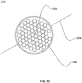
- FIG. 22 illustrates a cross-sectional view of an optical fibre cable 2200, in accordance with an embodiment of the present disclosure.
- FIG. 23 illustrates a cross-sectional view of another optical fibre cable 2300, in accordance with another embodiment of the present disclosure.
- the optical fibre cable 2200 includes 6 ribbons per buffer tube.
- the optical fibre cable 2200 is a type of cable that has a number of optical fibres for the transmission of a signal from one end to another end.
- Optical fibre cables are used to transfer digital data signals in the form of light up to distances of hundreds of miles.
- the optical fibre cable 2200 is defined along a longitudinal axis 2204.
- the longitudinal axis 2204 passes through a geometrical center 2202 of the optical fibre cable 2200.
- the longitudinal axis 2204 of the optical fibre cable 2200 is an imaginary axis along lengthwise direction of the optical fibre cable 2200.
- the longitudinal axis 2204 passes through the geometrical center 2202 of the optical fibre cable 2200.
- the geometrical center 2202 of the optical fibre cable 2200 is a central point of the optical fibre cable 2200. In other words, the geometrical center 2202 of the optical fibre cable 2200 is defined as a midpoint of diameter of the optical fibre cable 2200.
- the optical fibre cable 2200 includes the plurality of optical fibre ribbons 1906, 2006, 2106 and a jacket 2206.
- the plurality of optical fibre ribbons 1906, 2006, 2106 is arranged spirally inside one or more buffer tube.
- the jacket 2206 encloses the plurality of optical fibre ribbons 1906, 2006, 2106.
- the optical fibre cable 2200 includes a plurality of buffer tubes. Each of the plurality of buffer tubes corresponds to the buffer tube 1900 shown in FIG. 19 , FIG. 20 and FIG. 21 .
- the buffer tube 1900 includes 6 optical fibre ribbons. Each optical fibre ribbon includes 12 optical fibres. Thus, each buffer tube of the plurality of buffer tubes 1900 includes a total of 72 optical fibres.
- each of the plurality of buffer tubes 1900 may include any suitable number of optical fibre ribbons and each optical fibre ribbon may have any suitable number optical fibres.
- each of the plurality of buffer tubes 1900 may have any shape of cross-section.
- the shape may be square, rectangle, pentagon, triangle, hexagonal and the like.
- the optical fibre cable 2300 includes 12 ribbons per buffer tube.
- the optical fibre cable 2300 is a type of cable that has a number of optical fibres for the transmission of a signal from one end to another end.
- Optical fibre cables are used to transfer digital data signals in the form of light up to distances of hundreds of miles.
- the optical fibre cable 2300 is defined along a longitudinal axis 2304.
- the longitudinal axis 2304 passes through a geometrical center 2302 of the optical fibre cable 2300.
- the longitudinal axis 2304 of the optical fibre cable 2300 is an imaginary axis along lengthwise direction of the optical fibre cable 2300.
- the longitudinal axis 2304 passes through the geometrical center 2302 of the optical fibre cable 2300.
- the geometrical center 2302 of the optical fibre cable 2300 is a central point of the optical fibre cable 2300. In other words, the geometrical center 2302 of the optical fibre cable 2300 is defined as a midpoint of diameter of the optical fibre cable 2300.
- the optical fibre cable 2300 includes the plurality of optical fibre ribbons 1906, 2006, 2106 and a jacket 2306.
- the plurality of optical fibre ribbons 1906, 2006, 2106 is arranged spirally inside the one or more buffer tube.
- the jacket 2306 encloses the plurality of optical fibre ribbons 1906, 2006, 2106.
- the optical fibre cable 2300 includes the plurality of buffer tubes. Each of the plurality of buffer tubes corresponds to the buffer tube 1900 shown in FIG. 19 , FIG. 20 and FIG. 21 .
- the buffer tube 1900 in the optical fibre cable 2300 includes 12 optical fibre ribbons.
- Each optical fibre ribbon includes 12 optical fibres.
- each buffer tube of the plurality of buffer tubes 1900 includes a total of 144 optical fibres.
- each of the plurality of buffer tubes 1900 in the optical fibre cable 2300 may include any suitable number of optical fibre ribbons and each optical fibre ribbon may have any suitable number optical fibres.
- each of the plurality of buffer tubes 1900 in the optical fibre cable 2300 may have any shape of cross-section.
- the shape may be square, rectangle, pentagon, triangle, hexagonal and the like.
- the optical fibre cable 2200, 2300 may include at least one of a plurality of components selected from a group.
- the group includes a central strength member, peripheral strength member, water swellable yarns, water swellable tape, aramid yarns, sheath, ripcords, embedded strength member and the like.
- the buffer tube 1900 with 6 ribbons has higher packing efficiency than the buffer tube 1900 with 12 ribbons.
- an optical fibre cable with 6 ribbons per tube has a higher packing efficiency than an optical fibre cable with 12 ribbons per tube.
- the optical fibre cable 2200, 2300 further includes one or more of the one or more buffer tubes 1900 and one or more of one or more binding yarns and one or more binding tapes.
- the plurality of optical fibre ribbons 1906, 2006, 2106 is enclosed in the one or more buffer tubes 1900.
- the one or more of the one or more binding yarns and the one or more binding tapes are wound around the one or more buffer tubes 1900.
- the one or more buffer tube 1900 has a circular cross-section shape (as shown in FIG. 19 and FIG. 20 ).
- the one or more buffer tube 1900 has a hexagonal cross-section shape (as shown in FIG. 21 ).
- the optical fibre ribbons 1906, 2006, 2106 in the optical fibre cable 2200, 2300 are arranged in spirally out direction from a centre of the one or more buffer tube towards an inner wall of the one or more buffer tube 1900 in a curved shape.
- the plurality of optical fibre ribbons 1906, 2006, 2106 in the optical fibre cable 2200, 2300 are wrapped with one or more of one or more yarns, one or more binders, one or more tapes and one or more layers.
- the plurality of optical fibre ribbons 1906, 2006, 2106 in the optical fibre cable 2200, 2300 is arranged concentrically inside the one or more buffer tube 1900 in the plurality of circular arcs 104.
- the buffer tube 1900 may be replaced by aramid yarns or any other kind of yarns.
- the buffer tube 1900 may be replaced by and the plurality of optical fibre ribbons 1906, 2006, 2106 are wrapped with one or more of one or more yarns, one or more binders, one or more tapes and one or more layers.
- the spiral arrangement of the optical fibre ribbons has numerous advantages over the prior art.
- the spiral arrangement of the optical fibre ribbon in the buffer tube increases the packing efficiency of the buffer tube.
- the spiral arrangement of the optical fibre ribbons in the buffer tube results in high fibre density per tube.
- the spiral arrangement of the optical fibre ribbons in the buffer tube facilitates reduction in the cable diameter.
- the spiral arrangement of the optical fibre ribbons in the buffer tube lowers the point stresses on fibres of the ribbon.
- the spiral arrangement of the optical fibre ribbons in the buffer tube provides high density buffer tube in reduced cable diameter.
Abstract
Description
- The present disclosure relates to the field of optical fibre ribbons and, in particular, relates to a high density optical fibre ribbon stack and method for manufacturing the high density optical fibre ribbon stack.
- Over the last few years, optical fibre cables are widely used for communication over long distances. As a result, there is a demand for fibre optic cables with greater number of optical fibres. Optical fibre ribbons have been developed in order to meet the demands for increased optical fibre count in optical fibre cables. Optical fibre ribbons are planar arrays of optical fibres that are bonded together as a unit. Optical fibre ribbons are advantageous because many ribbons can be arranged together to form an optical fibre ribbon stack. Typically, the optical fibre ribbon stack is packed within a buffer tube with low packing efficiency. However, the low packing efficiency of the optical fibre ribbon stack within the buffer tube makes it challenging to reduce diameter of the optical fibre cable in which it is installed.
- In light of the above stated discussion, there is a need for an optical fibre ribbon stack which can overcome the above stated disadvantages.
- In an aspect, the present disclosure provides a method for arranging a plurality of optical fibre ribbons in an optical fibre cable. The method includes a set of steps. The set of steps include a first step of receiving the plurality of optical fibre ribbons. Moreover, the set of steps include a second step of arranging the plurality of optical fibre ribbons in a plurality of circular arcs in the optical fibre cable. The plurality of circular arcs is substantially parallel.
- A primary object of the present disclosure is to provide a high density optical fibre ribbon stack.
- Another object of the present disclosure is to provide the optical fibre ribbon stack with high packing efficiency.
- Yet another object of the present disclosure is to provide the optical fibre ribbon stack with bendable ribbons.
- Yet another object of the present disclosure is to provide the optical fibre ribbon stack enclosed in a buffer tube to optimize fibre packing density within optical fibre cable.
- Yet another object of the present disclosure is to provide a design and arrangement of dies and method for stacking ribbons in optical fibre cables.
- Yet another object of the present disclosure is to provide a method to stack high density optical fibre ribbon stack in a buffer tube in optical fibre cables.
- Yet another object of the present disclosure is to provide the optical fibre ribbon stack with bendable ribbons.
- Yet another object of the present disclosure is to provide the optical fibre ribbon stack enclosed in the buffer tube to optimize fibre packing efficiency within optical fibre cable.
- Yet another object of the present disclosure is to provide a method to increase packing density in high fibre count optical fibre cable.
- Yet another object of the present disclosure is to provide the optical fibre cable with high packing density of a buffer tube.
- In an embodiment of the present disclosure, the plurality of optical fibre ribbons is arranged concentrically by a guide.
- In an embodiment of the present disclosure, the plurality of optical fibre ribbons are wrapped with one or more of one or more yarns, one or more binders, one or more tapes and one or more layers.
- In an embodiment of the present disclosure, each circular arc of the plurality of circular arcs is in contact with at least one circular arc of the plurality of circular arcs.
- In an embodiment of the present disclosure, the plurality of circular arcs is in a buffer tube.
- In an embodiment of the present disclosure, the step of arranging the plurality of optical fibre ribbons further includes placing the plurality of optical fibre ribbons such that at least one of a top surface and a bottom surface of each optical fibre ribbon of the plurality of optical fibre ribbons is in contact with at least one optical fibre ribbon of the plurality of optical fibre ribbons.
- In an embodiment of the present disclosure, the plurality of circular arcs is concentric.
- In an embodiment of the present disclosure, the plurality of optical fibre ribbons are arranged such that placement of each optical fibre ribbon is defined by a radius and a radius of curvature. The placement of each optical fibre ribbon of the plurality of optical fibre ribbons is defined by a first radius of curvature.
- In an embodiment of the present disclosure, the plurality of optical fibre ribbons are arranged such that placement of each optical fibre ribbon is defined by a radius and a radius of curvature. An optical fibre ribbon defined by a first radius is not in contact with other optical fibre ribbon defined by the first radius.
- In another aspect, the present disclosure provides an optical fibre cable. The optical fibre cable includes a plurality of optical fibre ribbons and a jacket enclosing the plurality of optical fibre ribbons. The plurality of optical fibre ribbons are arranged in a plurality of circular arcs in the optical fibre cable. The plurality of circular arcs is substantially parallel.
- In an embodiment of the present disclosure, the optical fibre cable further includes one or more of one or more buffer tubes and one or more of one or more binding yarns and one or more binding tapes. The plurality of optical fibre ribbons are enclosed in the one or more buffer tubes. The one or more of the one or more binding yarns and the one or more binding tapes are wound around the one or more buffer tubes.
- In an embodiment of the present disclosure, the optical fibre cable further includes one or more of one or more yarns, one or more binders, one or more tapes and one or more layers. The one or more of the one or more yarns, the one or more binders, the one or more tapes and the one or more layers wraps the plurality of optical fibre ribbons.
- In an embodiment of the present disclosure, each of the plurality of optical fibre ribbons is arranged concentrically.
- In an embodiment of the present disclosure, each circular arc of the plurality of circular arcs is in contact with at least one circular arc of the plurality of circular arcs.
- In an embodiment of the present disclosure, the plurality of optical fibre ribbons are placed such that at least one of a top surface and a bottom surface of each optical fibre ribbon of the plurality of optical fibre ribbons is contact with at least one optical fibre ribbon of the plurality of optical fibre ribbons.
- In an embodiment of the present disclosure, the plurality of circular arcs is concentric.
- In an embodiment of the present disclosure, the plurality of optical fibre ribbons are arranged such that placement of each optical fibre ribbon is defined by a radius and a radius of curvature. The placement of each optical fibre ribbon of the plurality of optical fibre ribbons is defined by a first radius of curvature.
- In an embodiment of the present disclosure, the plurality of optical fibre ribbons are arranged such that placement of each optical fibre ribbon is defined by a radius and a radius of curvature. An optical fibre ribbon defined by a first radius is not in contact with other optical fibre ribbon defined by the first radius.
- In yet another aspect, the present disclosure provides a method for arranging a plurality of optical fibre ribbons in a buffer tube for use in an optical fibre cable. The method includes a set of steps. The set of steps include a first step of receiving a plurality of optical fibre ribbon. The set of steps include a second step of arranging the plurality of optical fibre ribbons in a spiral inside the buffer tube.
- In an embodiment of the present disclosure, the optical fibre ribbons are arranged in spirally out direction from a centre of the buffer tube towards an inner wall of the buffer tube in a curved shape.
- In an embodiment of the present disclosure, the method further includes one or more buffer tubes. The plurality of optical fibre ribbons are arranged in the one or more buffer tubes.
- In yet another aspect, the present disclosure provides an optical fibre cable. The optical fibre cable includes a plurality of optical fibre ribbons and a jacket. The plurality of optical fibre ribbons are arranged spirally inside one or more buffer tube. The jacket encloses the plurality of optical fibre ribbons.
- In an embodiment of the present disclosure, the optical fibre ribbons are arranged in spirally out direction from a centre of the one or more buffer tube towards an inner wall of the one or more buffer tube in a curved shape.
- In an embodiment of the present disclosure, the plurality of optical fibre ribbons are wrapped with one or more of one or more yarns, one or more binders, one or more tapes and one or more layers.
- In an embodiment of the present disclosure, the plurality of optical fibre ribbons is arranged concentrically inside the one or more buffer tube in a plurality of circular arcs.
- In an embodiment of the present disclosure, the optical fibre cable further includes one or more of the one or more buffer tubes and one or more of one or more binding yarns and one or more binding tapes. The plurality of optical fibre ribbons are enclosed in the one or more buffer tubes. The one or more of the one or more binding yarns and the one or more binding tapes are wound around the one or more buffer tubes.
- In an embodiment of the present disclosure, the one or more buffer tube has a circular cross-section shape.
- In an embodiment of the present disclosure, the one or more buffer tube has a hexagonal cross-section shape.
- In order to best describe the manner in which the above-described embodiments are implemented, as well as define other advantages and features of the disclosure, a more particular description is provided below and is illustrated in the appended drawings. Understanding that these drawings depict only exemplary embodiments of the invention and are not therefore to be considered to be limiting in scope, the examples will be described and explained with additional specificity and detail through the use of the accompanying drawings in which:
-
FIG. 1 illustrates a buffer tube enclosing a plurality of optical fibre ribbons, in accordance with an embodiment of the present disclosure; -
FIG. 2 illustrates an optical fibre cable with the plurality of optical fibre ribbons of theFIG. 1 , in accordance with another embodiment of the present disclosure; -
FIG. 3 illustrates another example of the optical fibre cable with the optical fibre ribbon stack ofFIG. 1 , in accordance with another embodiment of the present disclosure; -
FIG. 4 illustrates a cross sectional view of a machine holder, in accordance with various embodiments of the present disclosure; -
FIG. 5 illustrates a side view of the machine holder, in accordance with an embodiment of the present disclosure; -
FIG. 6 illustrates a general overview of a master die, in accordance with an embodiment of the present disclosure; -
FIG. 7 illustrates an internal cross sectional view of a first end of the master die, in accordance with an embodiment of the present disclosure; -
FIG. 8 illustrates an internal cross sectional view of a second end of the master die, in accordance with an embodiment of the present disclosure; -
FIG. 9 illustrates a cross sectional view of a section of the master die, in accordance with an embodiment of the present disclosure; -
FIG. 10 illustrates a general overview of a guide, in accordance with an embodiment of the present disclosure; -
FIG. 11 illustrates an internal view of a section of the guide, in accordance with an embodiment of the present disclosure; -
FIG. 12 illustrates a cross sectional view of a section of the guide, in accordance with an embodiment of the present disclosure; -
FIG. 13 illustrates a general overview of a master die holder, in accordance with an embodiment of the present disclosure; -
FIG. 14 illustrates an internal cross section view of the master die holder, in accordance with an embodiment of the present disclosure; -
FIG. 15 illustrates a side view of the master die holder, in accordance with another embodiment of the present disclosure; -
FIG. 16 illustrates an internal cross sectional view of the master die holder, in accordance with yet another embodiment of the present disclosure; -
FIG. 17 illustrates a cross sectional view of a lay plate holder, in accordance with an embodiment of the present disclosure; -
FIG. 18 illustrates a side section view of the lay plate holder, in accordance with an embodiment of the present disclosure; -
FIG. 19 illustrates a cross sectional view of a 144 fibre circular buffer tube with spiral arrangement of ribbons, in accordance with an embodiment of the present disclosure; -
FIG. 20 illustrates a cross sectional view of a 72 fibre circular buffer tube with spiral arrangement of ribbons, in accordance with an embodiment of the present disclosure; -
FIG. 21 illustrates a cross sectional view of a 72 fibre hexagonal shaped buffer tube with spiral arrangement of ribbons, in accordance with an embodiment of the present disclosure; -
FIG. 22 illustrates a cross sectional view of an optical fibre cable with spiral arrangement of ribbons inside buffer tubes, in accordance with an embodiment of the present disclosure; and -
FIG. 23 illustrates a cross sectional view of another optical fibre cable with spiral arrangement of ribbons inside buffer tubes, in accordance with another embodiment of the present disclosure. - It should be noted that the accompanying figures are intended to present illustrations of few exemplary embodiments of the present disclosure. These figures are not intended to limit the scope of the present disclosure. It should also be noted that accompanying figures are not necessarily drawn to scale.
- For a more complete understanding of the present invention parts, reference is now made to the following descriptions:
- 100. Buffer tube.
- 102. Plurality of optical fibre ribbons.
- 104. Plurality of circular arcs.
- 200. Optical fibre cable.
- 202. Buffer tubes.
- 204. Geometrical center.
- 206. Longitudinal axis.
- 208. Central strength member.
- 210 Jacket.
- 400. Machine holder.
- 402. Lay plate holder.
- 404. Lay plate.
- 406. Master die holder.
- 408. Master die.
- 410. Guide.
- 600. General overview.
- 602. First end.
- 604. Second end.
- 606. Main body.
- 1000. General overview.
- 1002. First region.
- 1004. Second region.
- 1006. Inner cylinder.
- 1008. Outer cylinder.
- 1010. First cylinder.
- 1012. Second cylinder.
- 1402. Bottom portion.
- 1404. Top portion.
- 1702. Upper part.
- 1704. Bottom part.
- 1706. Cavity.
- 1900. Buffer tube.
- 1902. Geometrical center.
- 1904. Longitudinal axis.
- 1906. Plurality of optical fibre ribbons.
- 2002. Geometrical center.
- 2004. Longitudinal axis.
- 2006. Plurality of optical fibre ribbons.
- 2102. Geometrical center.
- 2104. Longitudinal axis.
- 2106. Plurality of optical fibre ribbons.
- 2202. Geometrical center.
- 2204. Longitudinal axis.
- 2302. Geometrical center.
- 2304. Longitudinal axis.
- B1. Breadth.
- B2. Breadth.
- B3. Breadth.
- B4. Breadth.
- D1. Diameter.
- D2. Diameter.
- D3. Diameter.
- D4. Diameter.
- H1. Height.
- H2. Height.
- H3. Height.
- H4. Height.
- H5. Height.
- H6. Height.
- H7. Height.
- W1. Width.
- W3. Width.
- W4. Width.
- W5. Width.
- W6. Width.
- Ø1. Diameter.
- Ø2. Diameter.
- Ø3. Diameter.
- Ø4. Diameter.
- Ø5. Diameter.
- R1. Radius.
- R2. Radius.
- R3. Radius.
- R4. Radius.
- S1. Section.
- S2. Section.
- The following detailed description is of the best currently contemplated modes of carrying out exemplary embodiments of the invention. The description is not to be taken in a limiting sense, but is made merely for the purpose of illustrating the general principles of the invention.
- Reference in this specification to "one embodiment" or "an embodiment" means that a particular feature, structure, or characteristic described in connection with the embodiment is included in at least one embodiment of the present technology. The appearance of the phrase "in one embodiment" in various places in the specification are not necessarily all referring to the same embodiment, nor are separate or alternative embodiments mutually exclusive of other embodiments. Moreover, various features are described which may be exhibited by some embodiments and not by others. Similarly, various requirements are described which may be requirements for some embodiments but not for other embodiments.
- Reference will now be made in detail to selected embodiments of the present disclosure in conjunction with accompanying figures. The embodiments described herein are not intended to limit the scope of the disclosure, and the present disclosure should not be construed as limited to the embodiments described. This disclosure may be embodied in different forms without departing from the scope and spirit of the disclosure. It should be understood that the accompanying figures are intended and provided to illustrate embodiments of the disclosure described below and are not necessarily drawn to scale. In the drawings, like numbers refer to like elements throughout, and thicknesses and dimensions of some components may be exaggerated for providing better clarity and ease of understanding.
- Moreover, although the following description contains many specifics for the purposes of illustration, anyone skilled in the art will appreciate that many variations and/or alterations to said details are within the scope of the present technology. Similarly, although many of the features of the present technology are described in terms of each other, or in conjunction with each other, one skilled in the art will appreciate that many of these features can be provided independently of other features. Accordingly, this description of the present technology is set forth without any loss of generality to, and without imposing limitations upon, the present technology.
- It should be noted that the terms "first", "second", and the like, herein do not denote any order, ranking, quantity, or importance, but rather are used to distinguish one element from another. Further, the terms "a" and "an" herein do not denote a limitation of quantity, but rather denote the presence of at least one of the referenced item.
-
FIG. 1 illustrates abuffer tube 100 enclosing a plurality ofoptical fibre ribbons 102, in accordance with an embodiment of the present disclosure. In general, buffer tubes provide mechanical isolation to fibres present in the buffer tubes. The plurality ofoptical fibre ribbons 102 constitutes an optical fibre ribbon stack. In general, optical fibre ribbon stacks include a plurality of optical fibre ribbons arranged together within a matrix material. - The
buffer tube 100 includes the plurality ofoptical fibre ribbons 102. Thebuffer tube 100 is a loose tube. In general, optical fibre ribbons are made of a number of optical fibres bonded together. In an embodiment of the present disclosure, each optical fibre ribbon of the plurality ofoptical fibre ribbons 102 is a bendable ribbon. In general, bendable ribbons bend along non-preferential axis. Also, the bendable ribbons may be used to change stacking method of the arrangement of the plurality of optical fibre
ribbons 102. In general, the bendable ribbons are packed efficiently inside a loose tube. In an embodiment of the present disclosure, the plurality ofoptical fibre ribbons 102 is efficiently packed inside thebuffer tube 100. The efficient packing of the plurality ofoptical fibre ribbons 102 inside thebuffer tube 100 reduces overall diameter of any cable during installation of thebuffer tube 100 in the particular cable. [0018] The plurality ofoptical fibre ribbons 102 is arranged in a plurality ofcircular arcs 104. In an embodiment of the present disclosure, the plurality ofcircular arcs 104 is concentric. In an embodiment of the present disclosure, the plurality ofcircular arcs 104 is in abuffer tube 100. In another embodiment of the present disclosure, thebuffer tube 100 may be replaced by aramid yarns or any other kind of yarns. In another embodiment of the present disclosure, thebuffer tube 100 may be replaced by and the plurality ofoptical fibre ribbons 102 are wrapped with one or more of one or more yarns, one or more binders, one or more tapes and one or more layers. - In an embodiment of the present disclosure, number of the one or more layers of the plurality of
optical fibre ribbons 102 inside thebuffer tube 100 is 6. Each layer of the one or more layers consists of a bendable ribbon arranged in a circular arc fashion. In an embodiment of the present disclosure, the one or more layers include a first layer, a second layer, a third layer, a fourth layer, a fifth layer and a sixth layer. In an embodiment of the present disclosure, the first layer and the second layer includes one optical fibre ribbon each. In addition, the third layer and the fourth layer include two optical fibre ribbons each. Further, the fifth layer and the sixth layer include three optical fibre ribbons each. Furthermore, total number of the plurality ofoptical fibre ribbons 102 inside thebuffer tube 100 is twelve. - In yet another embodiment of the present disclosure, number of the one or more layers of the optical
fibre ribbon stack 102 inside thebuffer tube 100 may vary. In an embodiment of the present disclosure, each layer of the one or more layers of the opticalfibre ribbon stack 102 inside thebuffer tube 100 may have any number of optical fibre ribbons. In an embodiment of the present disclosure, packing ratio of thebuffer tube 100 may vary depending upon number of the plurality of optical fibre ribbons inside thebuffer tube 100. - In an embodiment of the present disclosure, each layer of the one or more layers is characterized by a diameter. The diameter of each layer of the one or more layers is different. In an example, number of the one or more layers of the optical fibre ribbon stack is three. The one or more layers include the first layer, the second layer and the third layer. The third layer surrounds the second layer. The second layer surrounds the first layer. Furthermore, the third layer has greater diameter than the first layer and the second layer. Moreover, the second layer has diameter greater than the first layer and smaller than the third layer. In addition, the first layer has smaller diameter than the second layer and the third layer.
- In an embodiment of the present disclosure, the plurality of
optical fibre ribbons 102 includes a plurality of optical fibres. Each optical fibre of the plurality of optical fibres has a diameter in the range of 160 to 250 micrometers. In general, an optical fibre refers to a medium associated with transmission of information over long distances in the form of light pulses. In addition, the optical fibre uses light to transmit voice and data communications over long distances. In an embodiment of the present disclosure, number of the optical fibres in each of the plurality ofoptical fibre ribbons 102 is 12. In another embodiment of the present disclosure, number of the optical fibres in each of the plurality ofoptical fibre ribbons 102 is 16. In yet another embodiment of the present disclosure, number of the optical fibres in each of the plurality ofoptical fibre ribbons 102 is 24. In yet another embodiment of the present disclosure, number of the optical fibres in each of the plurality ofoptical fibre ribbons 102 may vary. - In an embodiment of the present disclosure, the plurality of
optical fibre ribbons 102 are designed and arranged for optical fibre cables in which high fibre counts are required with high fibre density. -
FIG. 2 illustrates anoptical fibre cable 200 with the plurality ofoptical fibre ribbons 102 ofFIG. 1 , in accordance with another embodiment of the present disclosure. Theoptical fibre cable 200 is defined along alongitudinal axis 206 passing through ageometrical center 204 of theoptical fibre cable 200. Thelongitudinal axis 206 of theoptical fibre cable 200 is an imaginary axis along lengthwise direction of theoptical fibre cable 200. Thegeometrical center 204 of theoptical fibre cable 200 is a central point of theoptical fibre cable 200. In other words, thegeometrical center 204 of theoptical fibre cable 200 is defined as a midpoint of diameter of theoptical fibre cable 200. - The
optical fibre cable 200 includes the plurality ofoptical fibre ribbons 102 and ajacket 210. Thejacket 210 encloses the plurality ofoptical fibre ribbons 102. The plurality ofoptical fibre ribbons 102 are positioned inside a core of theoptical fibre cable 200. In an embodiment of the present disclosure, other additional elements such as buffer tubes, binders, tapes, yarns and the like may or may not be present inside theoptical fibre cable 200. The plurality ofoptical fibre ribbons 102 are arranged in the plurality ofcircular arcs 104 in theoptical fibre cable 200. The plurality ofcircular arcs 104 is substantially parallel. - In an embodiment of the present disclosure, the
optical fibre cable 200 may include one or more of one ormore buffer tubes 202. In an embodiment of the present disclosure, the plurality ofoptical fibre ribbons 102 may be enclosed in the one ormore buffer tubes 202. In another embodiment of the present disclosure, the plurality ofoptical fibre ribbons 102 may not be enclosed in the one ormore buffer tubes 202. In an embodiment of the present disclosure, theoptical fibre cable 200 may include one or more of one or more binding yarns and one or more binding tapes. In an embodiment of the present disclosure, the one or more of the one or more binding yarns and the one or more binding tapes may be wound around the one ormore buffer tubes 202. In an embodiment of the present disclosure, theoptical fibre cable 200 further includes one or more of one or more yarns, one or more binders, one or more tapes and one or more layers. The one or more of the one or more yarns, the one or more binders, the one or
more tapes and the one or more layers wraps the plurality of optical fibre ribbons. Further, each of the one ormore buffer tubes 202 provides protection to the plurality ofoptical fibre ribbons 102 from physical damage. Each of the one ormore buffer tubes 202 corresponds to thebuffer tube 100 shown inFIG. 1 . In an embodiment of the present disclosure, cross section of eachbuffer tube 100 of the one ormore buffer tubes 202 is circular in shape. In another embodiment of the present disclosure, shape of the one ormore buffer tubes 202 may vary. In an embodiment of the present disclosure, eachbuffer tube 100 of the one ormore buffer tubes 202 is similar in structure and dimensions. - In an embodiment of the present disclosure, number of the one or
more buffer tubes 202 in theoptical fibre cable 200 is 1. In addition, total number of the plurality of optical fibres corresponding to 1 buffer tube in theoptical fibre cable 200 is 192. Further, fibre density corresponding to 192 optical fibres in theoptical fibre cable 200 is 12.07. In another embodiment of the present disclosure, number of the one ormore buffer tubes 202 in theoptical fibre cable 200 is 6. Further, total number of the plurality of optical fibres corresponding to 6 buffer tubes in theoptical fibre cable 200 is 1152. Furthermore, fibre density corresponding to 1152 optical fibres in theoptical fibre cable 200 is 4.24. In yet another embodiment of the present disclosure, number of the one ormore buffer tubes 202 in theoptical fibre cable 200 is 12. Moreover, total number of the plurality of optical fibres corresponding to 12 buffer tubes in theoptical fibre cable 200 is 2304. Also, fibre density corresponding to 2304 optical fibres in theoptical fibre cable 200 is 5.36. In yet another embodiment of the present disclosure, number of the one ormore buffer tubes 202 in theoptical fibre cable 200 is 24. Moreover, total number of the plurality of optical fibres corresponding to 12 buffer tubes in theoptical fibre cable 200 is 4608. Also, fibre density corresponding to 4608 optical fibres in theoptical fibre cable 200 is 6.23. In yet another embodiment of the present disclosure, number of the one ormore buffer tubes 202 in theoptical fibre cable 200 is 48. Also, total number of the plurality of optical fibres corresponding to 48 buffer tubes in theoptical fibre cable 200 is 9216. Also, fibre density corresponding to 9216 optical fibres in theoptical fibre cable 200 is 7.23. - In yet another embodiment of the present disclosure, number of the one or
more buffer tubes 202 in theoptical fibre cable 200 may vary. In an embodiment of the present disclosure, total number of the plurality of optical fibres in theoptical fibre cable 200 may vary. - In an embodiment of the present disclosure, the
optical fibre cable 200 includes acentral strength member 208. The one ormore buffer tubes 202 surround thecentral strength member 208. In general, central strength member provides physical strength to a fibre cable and resists over bending of the fibre cable. In an embodiment of the present disclosure, thecentral strength member 208 provides tensile strength to theoptical fibre cable 200. In another embodiment of the present disclosure, theoptical fibre cable 200 may not include central strength member (as shown inFIG. 3 ). - Furthermore, the
optical fibre cable 200 includes thejacket 210. Thejacket 210 encloses the plurality ofoptical fibre ribbons 102. In an embodiment of the present disclosure, thejacket 210 surrounds the one ormore buffer tubes 202. In an embodiment of the present disclosure, thejacket 210 protects theoptical fibre cable 200 against crush, pressure and tensile stress. In addition, thejacket 210 provides stiffness, rigidity, and resistance to theoptical fibre cable 200. - The plurality of
optical fibre ribbons 102 is stacked inside theoptical fibre cable 200 according to a method. The method includes a set of steps. The set of steps include a first step of receiving the plurality ofoptical fibre ribbons 102. Moreover, the set of steps include a second step of arranging the plurality ofoptical fibre ribbons 102 in the plurality ofcircular arcs 104 in theoptical fibre cable 200. The plurality ofcircular arcs 104 is substantially parallel. In an embodiment of the present disclosure, each of the plurality ofoptical fibre ribbons 102 is arranged concentrically. - In an embodiment of the present disclosure, each circular arc of the plurality of
circular arcs 104 is in contact with at least one circular arc of the plurality ofcircular arcs 104. In an embodiment of the present disclosure, the step of arranging the plurality of
optical fibre ribbons 102 further includes placing the plurality ofoptical fibre ribbons 102 such that at least one of a top surface and a bottom surface of each optical fibre ribbon of the plurality ofoptical fibre ribbons 102 is in contact with at least one optical fibre ribbon of the plurality ofoptical fibre ribbons 102. - In an embodiment of the present disclosure, the plurality of
optical fibre ribbons 102 are arranged such that placement of each optical fibre ribbon is defined by a radius and a radius of curvature. The placement of each optical fibre ribbon of the plurality ofoptical fibre ribbons 102 is defined by a first radius of curvature. In an embodiment of the present disclosure, an optical fibre ribbon defined by a first radius is not in contact with other optical fibre ribbon defined by the first radius. -
FIG. 3 illustrates another example of theoptical fibre cable 200 with the optical fibre ribbon stack ofFIG. 1 , in accordance with another embodiment of the present disclosure. The optical fibre cable 200 (as shown inFIG. 3 ) is similar to the optical fibre cable 200 (as shown inFIG. 2 ) but does not include a central strength member. - The optical
fibre ribbon stack 102 enclosed in thebuffer tube 100 may be installed in any type of optical fibre cable. In general, types of optical fibre cable include armored optical fibre cable, fire retardant optical fibre cable, multi-loose tube optical fibre cable, high density optical fibre cable and the like. The optical fibre ribbons take less space inside thebuffer tube 100 due to the arrangement of the optical fibre ribbons in concentric circular arcs in multiple layers inside thebuffer tube 100. Also, the arrangement of the optical fibre ribbons in concentric circular arcs in multiple layers inside thebuffer tube 100 allows more number of ribbons to be arranged inside thebuffer tube 100. In addition, the arrangement of the optical fibre ribbons in concentric circular arcs in multiple layers inside multiple buffer tubes leads to increase in fibre density. - The
buffer tube 100 includes the opticalfibre ribbon stack 102. Thebuffer tube 100 is a loose tube. Further, theribbon stack 102 includes a plurality of optical fibre ribbons. In general, optical fibre ribbons are made of number of optical fibres bonded together. In an embodiment of the present disclosure, each ribbon of the plurality of optical fibre ribbons in theribbon stack 102 is a bendable ribbon. In general, bendable ribbons are capable to bend along non-preferential axis. Also, the bendable ribbons may be used to change stacking method of the plurality of ribbons. In general, the bendable ribbons are packed efficiently inside a loose tube. In an embodiment of the present disclosure, theribbon stack 102 is efficiently packed inside thebuffer tube 100. The efficient packing of the opticalfibre ribbon stack 102 inside thebuffer tube 100 reduces overall diameter of any cable during installation of thebuffer tube 100 in the particular cable. - In an embodiment of the present disclosure, the plurality of optical fibre ribbons in the optical
fibre ribbon stack 102 is arranged inside thebuffer tube 100 in concentric circular arcs in a number of layers. In another embodiment of the present disclosure, the plurality of optical fibre ribbons in the optical fibre ribbon stack is arranged inside thebuffer tube 100 in any suitable arrangement of the like. Further, each layer includes at least one optical fibre ribbon arranged in a circular manner. In an embodiment of the present disclosure, each layer of the optical fibre ribbon stack may have any number of optical fibre ribbons. In another embodiment of the present disclosure, each layer of the optical fibre ribbon stack may have same number of optical fibre ribbons. In yet another embodiment of the present disclosure, each layer of the optical fibre ribbon stack may have different number of optical fibre ribbons. In an example, length of the plurality of optical fibre ribbons of each layer is different when each layer has same number of optical fibre ribbons. In another example, length of the plurality of optical fibre ribbons of each layer may be same or different when each layer has different number of the plurality of optical fibre ribbons. - In an embodiment of the present disclosure, the optical fibre ribbon stack is designed for optical fibre cables in which high fibre counts are required with high fibre density. In another embodiment of the present disclosure, the optical fibre ribbon stack is designed for optical fibre cables in which lower fibre counts are required. In yet another embodiment of the present disclosure, the design of the ribbon stack depends on the type of application of the optical fibre cable.
- The optical
fibre ribbon stack 102 enclosed in thebuffer tube 100 may be installed in any type of optical fibre cable. In general, types of optical fibre cable include single mode optical fibre cable, multimode optical fibre cable, armored optical fibre cable, high density optical fibre ribbons cable and the like. In addition, types of optical fibre cable include optical fibre cable with central strength member and optical fibre cable without central strength member. - The optical fibre ribbon stack has numerous advantages over the prior art. The optical fibre ribbon stack has high fibre density. The optical fibre ribbon stack is efficiently packed inside the buffer tube. The efficient packing of the optical fibre ribbon stack inside the buffer tube reduces overall diameter of the optical fibre cable. In addition, the efficient packing of optical fibre ribbon stack inside the buffer tube provides low point stresses on the plurality of optical fibres.
-
FIG. 4 illustrates a general overview of amachine holder 400, in accordance with various embodiments of the present disclosure. Themachine holder 400 guides a plurality of bendable optical fibre ribbons into a concentric circular form. Themachine holder 100 includes alay plate holder 402, alay plate 404, amaster die holder 406, a master die 408 and aguide 410. Thelay plate holder 402, thelay plate 404, the master die holder 106, the master die 108 and the guide 110 are arranged to enable movement of the plurality of bendable optical fibre ribbons in a concentric circular direction. Themachine holder 400 is utilized to manufacture the opticalfibre ribbon stack 102 ofFIG. 1 . - In an embodiment of the present disclosure, the
lay plate 404 is utilized to hold a plurality of optical fibre ribbons. In addition, the plurality of optical fibre ribbons is inserted into thelay plate 404. In general, optical fibre ribbons include a number of optical fibres arranged together within a matrix material. In addition, multiple individual optical ribbons can be stacked into a bundle to form a ribbon stack. Further, each of the plurality of optical fibre ribbons includes a plurality of optical fibres. In general, an optical fibre refers to a medium associated with transmission of information over long distances in the form of light pulses. In addition, the optical fibre uses light to transmit voice and data communications over long distances. Further, each of the plurality of optical fibre ribbons is a bendable ribbon. In general, bendable ribbons are capable to bend along non-preferential axis. Also, the bendable ribbons may be used to change stacking method of the plurality of optical fibre ribbons. - The
lay plate 404 is mounted inside themachine holder 400 with facilitation of thelay plate holder 402. Thelay plate holder 402 holds thelay plate 404 in themachine holder 400. In an embodiment of the present disclosure, thelay plate 404 is fixed in thelay plate holder 402. Thelay plate 404 is circular in shape. In an embodiment of the present disclosure, shape of thelay plate 404 may vary. Thelay plate 404 includes a plurality of slots. In an embodiment of the present disclosure, the plurality of optical fibre ribbons is placed in thelay plate 404. The plurality of slots is utilized for holding the plurality of bendable optical fibre ribbons in thelay plate 404. Each ribbon of the plurality of optical fibre ribbons is placed in an individual slot of the plurality of slots of thelay plate 404. In an embodiment of the present disclosure, number of the plurality of slots in thelay plate 404 is in range of about 6 to 72. In another embodiment of the present disclosure, number of the plurality of slots in thelay plate 404 is in range of about 12 to 36. In yet another embodiment of the present disclosure, range of number of the plurality of slots in thelay plate 404 may vary according to number of optical fibre ribbons. The plurality of slots in thelay plate 404 is designed in shape of concentric circular or spiral arcs. The plurality of bendable optical fibre ribbons is arranged into concentric circular or spiral arcs with facilitation of thelay plate 404. In addition, the plurality of optical fibre ribbons is arranged into concentric circular arcs with facilitation of thelay plate 404. - Further, the plurality of optical fibre ribbons arranged into concentric circular arcs is passed through the master die 408. The plurality of optical fibre ribbons take desired
bendable shape in concentric form after passing through the master die 408. The structure of the master die 408 allows the plurality of optical fibre ribbons to take desirable bendable shape in concentric form. In an embodiment of the present disclosure, the plurality of optical fibre ribbons forms an optical fibre ribbon stack after passing through the master die 408. The master die 408 is placed in themachine holder 400. The master die 408 is placed in themachine holder 400 with facilitation of the master dieholder 406. In an embodiment of the present disclosure, the master die 408 is placed along with theguide 410 mounted inside the master dieholder 406. The master dieholder 406 holds the master die 408 in fixed position. In an embodiment of the present disclosure, the master die 408 includes a plurality of grooves. In addition, number of the plurality of grooves in the master die 408 is in range of about 6 to 72. In an embodiment of the present disclosure, range of number of the plurality of grooves in the master die 408 may vary. - Furthermore, the optical fibre ribbon stack passes through the
guide 410. In an embodiment of the present disclosure, theguide 410 surrounds the master die 408. Theguide 410 is positioned along with the master die 408 in the master dieholder 406. In an embodiment of the present disclosure, theguide 410 has cylindrical shape. In another embodiment of the present disclosure, shape of theguide 410 may vary. Theguide 410 facilitates in compaction of the plurality of optical fibre ribbons of the optical fibre ribbon stack in desired concentric shape. In an embodiment of the present disclosure, the plurality of optical fibre ribbons is arranged concentrically by theguide 410. Moreover, the optical fibre ribbon stack of desired concentric shape comes out of theguide 410. In an embodiment of the present disclosure, the optical fibre ribbon stack coming out of theguide 410 is wrapped around smooth rectangular shaped paper tape. The paper tape maintains integrity of the optical fibre ribbon stack. - In an embodiment of the present disclosure, the plurality of bendable optical fibre ribbons passes from the master die 408. In an embodiment of the present disclosure, the plurality of bendable optical fibre ribbons forms an optical fibre ribbon stack after passing through the master die 408. In an embodiment of the present disclosure, the
master die 408 is placed in themachine holder 400 at a distance of about 100 millimeter to 500 millimeter from thelay plate 404. The optical fibre ribbon stack is passed through a hollow cylindrical die. The hollow cylindrical die is present inside extruder head. In addition, extruder head has inner diameter equal to outer diameter of the optical fibre ribbon stack. In an embodiment of the present disclosure, the optical fibre ribbon stack passes through the hollow cylindrical die present inside extruder head. Further, the optical fibre ribbon stack is pushed inside a buffer tube. - The
machine holder 400 enables production of high fibre count optical fibre cables with smaller diameter. The high fibre count is due to the arrangement of the optical fibre ribbons in concentric circular arcs in multiple layers inside the buffer tube. Also, the arrangement of the optical fibre ribbons in concentric circular arcs in multiple layers inside the buffer tube allows more number of ribbons to be arranged inside the buffer tube. In addition, themachine holder 400 enables lower mechanical stresses on the fibres inside the plurality of bendable optical fibre ribbons. Moreover, the stresses are reduced due to the arrangement of the optical fibre ribbons in concentric circular arcs in multiple layers inside the buffer tube. Further, themachine holder 100 enables highly packed buffer tubes with large number of optical fibres and high fibre density in same cable diameter due to the concentric arrangement. -
FIG. 5 illustrates a side view of themachine holder 400, in accordance with an embodiment of the present disclosure. In an embodiment of the present disclosure, themachine holder 400 has a height H1 of about 365.00 mm. In another embodiment of the present disclosure, the height H1 of themachine holder 400 may vary. In an embodiment of the present disclosure, themachine holder 400 has a width W1 of about 167.14 mm. In another embodiment of the present disclosure, the width W1 of themachine holder 400 may vary. In an embodiment of the present disclosure, thelay plate holder 402 has a height H2 of about 20.00 mm. In another embodiment of the present disclosure, the height H2 of thelay plate holder 402 may vary. In an embodiment of the present disclosure, thelay plate holder 402 is placed at themachine holder 400 at
height H3 of about 131.00 mm. In another embodiment of the present disclosure, the height H3 of thelay plate holder 402 at themachine holder 400 may vary. -
FIG. 6 illustrates a general overview 600 of the master die 408, in accordance with an embodiment of the present disclosure. The master die 408 includes afirst end 602, asecond end 604 and amain body 606. Themain body 606 of the master die 408 is positioned between thefirst end 602 of the master die 408 and thesecond end 604 of the master die 408. The master die 408 has cylindrical shape extending from thefirst end 602 to thesecond end 604. In an embodiment of the present disclosure, the master die 408 includes the plurality of grooves. In addition, the plurality of grooves extends from thefirst end 602 of the master die 408 to thesecond end 604 of the master die 408. In an embodiment of the present disclosure, the plurality of grooves of the master die 408 has shape of concentric circular arcs. In another embodiment of the present disclosure, the shape of the plurality of grooves of the master die 408 may vary. In an embodiment of the present disclosure, the plurality of grooves is arranged in one or more layers. In addition, the one or more layers include a first layer, a second layer, a third layer, and a fourth layer. In another embodiment of the present disclosure, number of the one or more layers may vary. -
FIG. 7 illustrates an internal crosssectional view 700 of thefirst end 602 of the master die 408, in accordance with an embodiment of the present disclosure. Thefirst end 602 of the master die 408 includes the one or more layers of the plurality of grooves. In an embodiment of the present disclosure, the one or more layers of the plurality of grooves in thefirst end 602 of the master die 408 includes the first layer, the second layer, the third layer and the fourth layer. In another embodiment of the present disclosure, number of the one or more layer of the plurality of grooves in thefirst end 602 of the master die 408 may vary. In an embodiment of the present disclosure, the first layer of the plurality of grooves of thefirst end 602 of the master die 408 has a radius R1 of about 28. In another embodiment of the present disclosure, the radius R1 of the first layer of the plurality of grooves of thefirst end 602 of the master die 408 may vary. In an embodiment of the present disclosure, the second layer of the plurality of
grooves of thefirst end 602 of the master die 408 has a radius R2 of about 33. In another embodiment of the present disclosure, the radius R2 of the second layer of the plurality of grooves of thefirst end 602 of the master die 408 may vary. In an embodiment of the present disclosure, the third layer of the plurality of grooves of thefirst end 602 of the master die 408 has a radius R3 of about 38. In another embodiment of the present disclosure, the radius R3 of the third layer of the plurality of grooves of thefirst end 602 of the master die 408 may vary. In an embodiment of the present disclosure, the fourth layer of the plurality of grooves of thefirst end 602 of the master die 408 has a radius R4 of about 43. In another embodiment of the present disclosure, the radius R4 of the fourth layer of the plurality of grooves of thefirst end 602 of the master die 408 may vary. Further, the fourth layer of the plurality of grooves of thefirst end 602 of the master die 408 is explained further inFig. 9 . -
FIG. 8 illustrates an internal crosssectional view 800 of thesecond end 604 of the master die 408, in accordance with an embodiment of the present disclosure. Thesecond end 604 of the master die 408 includes the one or more layers of the plurality of grooves. In an embodiment of the present disclosure, the one or more layers of the plurality of grooves in thesecond end 604 of the master die 408 includes the first layer, the second layer, the third layer and the fourth layer. In another embodiment of the present disclosure, number of the one or more layer of the plurality of grooves in thesecond end 604 of the master die 408 may vary. In an embodiment of the present disclosure, the first layer of the plurality of grooves of thesecond end 604 of the master die 408 has a radius of about 80. In another embodiment of the present disclosure, the radius of the first layer of the plurality of grooves of thesecond end 604 of the master die 408 may vary. In an embodiment of the present disclosure, the second layer of the plurality of grooves of thesecond end 604 of the master die 408 has a radius of about 85. In another embodiment of the present disclosure, the radius of the second layer of the plurality of grooves of the second end 304 of the master die 108 may vary. In an embodiment of the present disclosure, the third layer of the plurality of grooves of thesecond end 604 of the master die 408 has a radius of about 90. In another embodiment
of the present disclosure, the radius of the third layer of the plurality of grooves of thesecond end 604 of the master die 408 may vary. - In an embodiment of the present disclosure, the first layer of the plurality of grooves of the
second end 604 of the master die 408 has a diameter Ø1 of about 5.18. In another embodiment of the present disclosure, the diameter Ø1 of the first layer of the plurality of grooves of thesecond end 604 of the master die 408 may vary. In an embodiment of the present disclosure, the second layer of the plurality of grooves of thesecond end 604 of the master die 408 has a diameter Ø2 of about 8.58. In another embodiment of the present disclosure, the diameter Ø2 of the second layer of the plurality of grooves of thesecond end 604 of the master die 408 may vary. In an embodiment of the present disclosure, the third layer of the plurality of grooves of thesecond end 604 of the master die 408 has a diameter Ø3 of about 11.04. In another embodiment of the present disclosure, the diameter Ø3 of the third layer of the plurality of grooves of thesecond end 604 of the master die 408 may vary. In an embodiment of the present disclosure, the fourth layer of the plurality of grooves of thesecond end 604 of the master die 408 has a diameter Ø4 of about 13.96. In another embodiment of the present disclosure, the diameter Ø4 of the fourth layer of the plurality of grooves of thesecond end 604 of the master die 408 may vary. In an embodiment of the present disclosure, the fifth layer of the plurality of grooves of thesecond end 604 of the master die 408 has a diameter Ø5 of about 17.16. In another embodiment of the present disclosure, the diameter Ø5 of the fifth layer of the plurality of grooves of thesecond end 604 of the master die 408 may vary (as shown inFIG. 8 ). Further, the fifth layer of the plurality of grooves of thesecond end 604 of the master die 408 is explained further inFig. 9 . -
FIG. 9 illustrates across section view 900 of a section of the master die 408, in accordance with an embodiment of the present disclosure. In an embodiment of the present disclosure, the master die 408 has a breadth B1 of about 15.00 mm. In another embodiment of the present disclosure, the breadth B1 of the master die 408 may vary. In an embodiment of the present disclosure, thefirst end 602 of the master die 408 has
a height h1 of about 7.00 mm. In another embodiment of the present disclosure, the height h1 of thefirst die 602 of the master die 408 may vary. In an embodiment of the present disclosure, thesecond end 604 of the master die 408 has a height h2 of about 10.50 mm. In another embodiment of the present disclosure, the height h2 of thesecond end 604 of the master die 408 may vary. -
FIG. 10 illustrates ageneral overview 1000 of theguide 410, in accordance with an embodiment of the present disclosure. Theguide 410 is positioned along with the master die 408 in the master dieholder 406. Theguide 410 includes afirst region 1002 and asecond region 1004. In an embodiment of the present disclosure, thefirst region 1002 is cylindrical in shape. In another embodiment of the present disclosure, thefirst region 1002 is of any suitable shape. In an embodiment of the present disclosure, thesecond region 1004 is cylindrical in shape. In another embodiment of the present disclosure, thesecond region 1004 is of any suitable shape. -
FIG. 11 illustrates aninternal view 1100 of a section of aguide 410, in accordance with an embodiment of the present disclosure. Further, thefirst region 1002 includes aninner cylinder 1006 and an outer cylinder 1008 (as shown inFIG. 10 ). In an embodiment of the present disclosure, theinner cylinder 1006 has a diameter d1 of about 4.50 mm. In another embodiment of the present disclosure, the diameter d1 of theinner cylinder 1006 may vary. In an embodiment of the present disclosure, theouter cylinder 1008 has a diameter d2 of about 5.90 mm. In another embodiment of the present disclosure, the diameter d2 of theouter cylinder 1008 may vary. Furthermore, thesecond region 1004 includes afirst cylinder 1010 and a second cylinder 1012 (as shown inFIG. 10 ). In an embodiment of the present disclosure, thefirst cylinder 1010 has a diameter d3 of about 5.90 mm. In another embodiment of the present disclosure, the diameter d3 of thefirst cylinder 1010 may vary. In an embodiment of the present disclosure, thesecond cylinder 1012 has a diameter d4 of about 7.00 mm. In another embodiment of the present disclosure, the diameter d4 of thesecond cylinder 1012 may vary. -
FIG. 12 illustrates ageneral overview 1200 of inner section of theguide 410, in accordance with an embodiment of the present disclosure. In addition,FIG. 12 illustrates inner section of thefirst region 1002 of theguide 410. Thefirst region 1002 includes theinner cylinder 1006 and the outer cylinder 1008 (as explained above). -
FIG. 13 illustrates ageneral overview 1300 of the master dieholder 406 ofFIG. 1 , in accordance with an embodiment of the present disclosure. The master dieholder 406 holds the master die 408 in fixed position. -
FIG. 14 illustrates an internalcross section view 1400 of the master dieholder 406, in accordance with an embodiment of the present disclosure. In an embodiment of the present disclosure, the master dieholder 406 has a height H3 of about 30.00 mm. In another embodiment of the present disclosure, the height H3 of the machine dieholder 406 may vary. In addition, the machine dieholder 406 includesbottom portion 1402,top portion 1404, a section S1 and a hole. The section S1 and a hole are positioned at thebottom portion 1402 of the master dieholder 406. Thetop portion 1404 includes a section S2, a section S3, and a section S4. In an embodiment of the present disclosure, thebottom portion 1402 of the master dieholder 406 has a width W4 of about 22.00 mm. In another embodiment of the present disclosure, the width W4 of thebottom portion 1402 of the master die holder 106 may vary. In an embodiment of the present disclosure, the section S2 of thetop portion 1404 of the master dieholder 406 has a breadth B4 of about 20.00 mm. In another embodiment of the present disclosure, the breadth B4 of the section S2 of the top portion 1104 of the master die holder 106 may vary. In an embodiment of the present disclosure, the section S3 of thetop portion 1404 of the master dieholder 406 has a breadth B3 of about 25.00 mm. In another embodiment of the present disclosure, the breadth B3 of the section S3 of thetop portion 1404 of the master dieholder 406 may vary. In an embodiment of the present disclosure, the section S3 of thetop portion 1404 has a height of about 3.00 mm. In another embodiment of the present disclosure, the height of the section S3 of thetop portion 1404 of the master dieholder 406 may vary (as shown inFIG. 14 ). - In an embodiment of the present disclosure, the section S4 of the
top portion 1404 of the master dieholder 406 has a breadth B2 of about 30.00 mm. In another embodiment of the present disclosure, the breadth B2 of the section S4 of thetop portion 1404 of the master dieholder 406 may vary. In an embodiment of the present disclosure, the section S4 of thetop portion 1404 of the master die 406 has a height of about 5.00 mm. In another embodiment of the present disclosure, the height of the section S4 of thetop portion 1404 of the master dieholder 406 may vary. (as shown inFIG. 14 ) - In an embodiment of the present disclosure, the section S1 has width of about 13.31 mm in accordance with the
bottom portion 1402 of the machine dieholder 406. In another embodiment of the present disclosure, width of the section S1 in accordance with thebottom portion 1402 of the machine dieholder 406 may vary. In an embodiment of the present disclosure, the section S1 has a width W3 of about 5.90 mm in accordance with thetop portion 1404 of the machine dieholder 406. In another embodiment of the present disclosure, the width W3 of the section S1 in accordance with thetop portion 1404 of the machine dieholder 406 may vary. In an embodiment of the present disclosure, distance D1 between the section S1 and the section S2 is of about 15.02 mm. In another embodiment of the present disclosure, the distance D1 between the section S1 and the section S2 may vary. In an embodiment of the present disclosure, distance D2 between the section S1 and the section S3 is of about 25.00 mm. In another embodiment of the present disclosure, the distance D2 between the section S1 and the section S3 may vary. (as shown inFIG. 14 ) -
FIG. 15 illustrates aside view 1500 of the machine dieholder 406, in accordance with another embodiment of the present disclosure. In an embodiment of the present disclosure, the machine dieholder 406 has width W5 of about 18 mm. In another embodiment of the present disclosure, the width W5 of the machine dieholder 406 may vary. In an embodiment of the present disclosure, the machine dieholder 406 has a height H4 of about 14 mm. In another embodiment of the present disclosure, the height H4 of the machine dieholder 406 may vary. -
FIG. 16 illustrates ageneral overview 1600 of the machine dieholder 406, in accordance with another embodiment of the present disclosure. The master die holder 106 holds the master die 108 in fixed position. -
FIG. 17 illustrates ageneral overview 1700 of thelay plate holder 402, in accordance with an embodiment of the present disclosure. In an embodiment of the present disclosure, thelay plate holder 402 includes anupper part 1702 and abottom part 1704. In an embodiment of the present disclosure, theupper part 1702 of thelay plate holder 402 has a breadth B5 of about 160.00 mm. In another embodiment of the present disclosure, the breadth B5 of theupper part 1702 of thelay plate holder 402 may vary. In an embodiment of the present disclosure, thelay plate holder 402 has a height H5 of about 40 mm. In another embodiment of the present disclosure, the height H5 of thelay plate holder 402 may vary. In an embodiment of the present disclosure, theupper part 1702 of thelay part holder 402 has a height H6 of about 15.00 mm. In another embodiment of the present disclosure, the height H6 of theupper part 1702 of thelay plate holder 402 may vary. Thebottom part 1704 of thelay plate holder 402 includes acavity 1706. Thecavity 1706 is placed at center of thelay plate holder 402. -
FIG. 18 illustrates aside section view 1800 of thelay plate holder 402, in accordance with an embodiment of the present disclosure. In an embodiment of the present disclosure, thecavity 1706 of thebottom part 1704 of thelay plate holder 402 has a diameter D3 of about 19.00 mm. In another embodiment of the present disclosure, the diameter D3 of thecavity 1706 of thebottom part 1704 may vary. In an embodiment of the present disclosure, thebottom part 1704 of thelay plate holder 402 has a height H7of about 22.00 mm. In another embodiment of the present disclosure, the height H7 of thebottom part 1704 of thelay plate holder 402 may vary. In an embodiment of the present disclosure, theupper part 1702 of thelay plate holder 402 has width W6 of about 20.00 mm. In another embodiment of the present disclosure, the width W6 of theupper part 1702 of thelay plate holder 402 may vary. -
FIG. 19 illustrates a cross sectional view of abuffer tube 1900, in accordance with various embodiments of the present disclosure.FIG. 20 illustrates another cross sectional view of thebuffer tube 1900, in accordance with another embodiment of the present disclosure.FIG. 21 illustrates yet another cross sectional view of thebuffer tube 1900, in accordance with yet another embodiment of the present disclosure. In an embodiment of the present disclosure, thebuffer tube 1900 may be circular in shape (as shown inFIG. 19 andFIG. 20 ). In another embodiment of the present disclosure, thebuffer tube 1900 may have a hexagonal shape (as shown inFIG. 21 ). In yet another embodiment of the present disclosure, thebuffer tube 1900 may be of any shape. In an embodiment of the present disclosure, thebuffer tube 1900 is a circular shaped buffer tube with 144 optical fibres. Thebuffer tube 1900 ofFIG. 19 is defined along alongitudinal axis 1904. In addition, thelongitudinal axis 1904 passes through ageometrical center 1902 of thebuffer tube 1900. Thelongitudinal axis 1904 of thebuffer tube 1900 is an imaginary axis along lengthwise direction of thebuffer tube 1900. Thelongitudinal axis 1904 passes through thegeometrical center 1902 of thebuffer tube 1900. Thegeometrical center 1902 of thebuffer tube 1900 is a central point of thebuffer tube 1900. In other words, thegeometrical center 1902 of thebuffer tube 1900 is defined as a midpoint of diameter of thebuffer tube 1900. Thebuffer tube 1900 is circular in shape. Thebuffer tube 1900 has circular cross-section. In an embodiment of the present disclosure, shape of thebuffer tube 1900 may vary. In general, thebuffer tube 1900 protects optical fibre ribbons from any damage. Further, thebuffer tube 1900 provides mechanical isolation, physical damage protection and identification of fibres. In an embodiment of the present disclosure, the buffer tube is a loose tube. - The
buffer tube 1900 includes a plurality ofoptical fibre ribbons 1906 inFIG. 1 . The plurality ofoptical fibre ribbons 1906 is arranged inside thebuffer tube 1900 in spiral form. Each of the plurality ofoptical fibre ribbons 1906 includes a plurality of optical fibres. In general, theoptical fibre ribbon 1906 is an array of optical fibres placed side by side. In other words, the plurality of optical fibres is placed side by side to form the optical fibre ribbon. In an embodiment of the present disclosure, a matrix bonding material encases the plurality of optical fibres to form the optical fibre ribbon. In an
embodiment of the present disclosure, the matrix bonding material is a UV curable bonding material. In addition, each of the plurality of optical fibre ribbon is a bendable optical fibre ribbon. The bendable optical fibre ribbon is a flexible ribbon. Each of the plurality of optical fibre ribbons is arranged spirally inside thebuffer tube 1900. The spiral arrangement of theoptical fibre ribbons 1906 enables reduction in point stresses on the plurality of optical fibres. In addition, the spiral arrangement of theoptical fibre ribbons 1906 enables high density of optical fibres in an optical fibre cable with small diameter. - In an embodiment of the present disclosure, each of the plurality of optical fibres is a fibre used for transmitting information as light pulses from one end to another. In addition, each of the plurality of optical fibres is a thin strand of glass capable of transmitting optical signals. Also, each of the plurality of optical fibres is configured to transmit large amounts of information over long distances with relatively low attenuation. Further, each of the plurality of optical fibres includes a core region and a cladding region. The core region is an inner part of an optical fibre and the cladding section is an outer part of the optical fibre. In addition, the cladding region surrounds the core region.
- The plurality of
optical fibre ribbons 1906 are arranged spirally inside thebuffer tube 1900. Each of the plurality ofoptical fibre ribbons 1906 includes a first edge and a second edge. The plurality ofoptical fibre ribbons 1906 are arranged in such a way that the first edge of each optical fibre ribbon of the plurality ofoptical fibre ribbons 1906 touches the first edge of two adjacent optical fibre ribbons of the plurality of optical fibre ribbons 1906 (as shown inFIG. 19 ). Each optical fibre ribbon of the plurality ofoptical fibre ribbons 1906 is a bendable optical fibre ribbon. - The plurality of
optical fibre ribbons 1906 is arranged spirally inside thebuffer tube 1900 to improve the packing efficiency of thebuffer tube 1900. The plurality ofoptical fibre ribbons 1906 is arranged in thebuffer tube 1900 in the form of a ribbon stack. In general, the ribbon stack is the arrangement of the plurality of ribbons in desired shape. The desired shape may correspond to rectangular shape, square shape,
spiral shape and the like. Thebuffer tube 1900 include spiral shape ribbon stack. The plurality of ribbons is arranged in thebuffer tube 1900 to form the spiral shape ribbon stack. Each of the plurality of optical fibre ribbons is a colored optical fibre ribbon. In an embodiment of the present disclosure, the color of each of the pluralityoptical fibre ribbons 1906 is different from other optical fibre ribbon of the plurality of optical fibre ribbon. Each of the plurality of optical fibre ribbon has a different color. In another embodiment of the present disclosure, the color of each of the plurality of optical fibre ribbon may vary according to the requirement or application. Each optical fibre ribbon of the plurality of optical fibre ribbon includes 12 optical fibres. In an embodiment of the present disclosure, each optical fibre ribbon of the plurality of optical fibre ribbons may include any suitable number of fibres. In an embodiment of the present disclosure, each optical fibre ribbon touches at least one optical fibre ribbon inside the tube. In an example, the top surface of a ribbon touches bottom surface of another ribbon. In another example, the bottom and top surfaces of a ribbon touches adjacent ribbon. The plurality ofoptical fibre ribbons 1906 is arranged spirally inside the buffer tube 1900 (as shown inFIG. 19 ). The spiral arrangement of the plurality ofoptical fibre ribbons 1906 is due to the flexible and bendable nature of the optical fibre ribbon. The spiral arrangement of the plurality ofoptical fibre ribbons 1906 improves the packing efficiency/density of the optical fibre ribbon inside thebuffer tube 1900. - In an embodiment of the present disclosure, the
buffer tube 1900 includes the plurality ofoptical fibre ribbons 1906. The plurality ofoptical fibre ribbons 1906 corresponds to 12 optical fibre ribbons. Each of the plurality ofoptical fibre ribbons 1906 includes the plurality of optical fibres. The plurality of optical fibres corresponds to 12 optical fibres. Thebuffer tube 1900 includes a total of 144 optical fibres (12 * 12 = 144). In an embodiment of the present disclosure, thebuffer tube 1900 with 12 optical fibre ribbons with each optical fibre having a diameter of 200 microns has an inner diameter of about 2.8 millimeters and an outer diameter of about 3.2 millimeters. In an embodiment of the present disclosure, thebuffer tube 1900 with 12 optical fibre ribbons with each optical fibre having a diameter of 200 microns has a thickness of about 0.2 millimeter. In an embodiment of the present disclosure, the buffer tube with 12 optical
fibre ribbon may have any suitable diameter. In an embodiment of the present disclosure, fibre diameter may vary. In an embodiment of the present disclosure, the buffer tube with 12 optical fibre ribbon may have any suitable thickness. Furthermore, thebuffer tube 1900 with 12 optical fibre ribbons has a packing efficiency of about 56.25 %. In general, the packing efficiency is the fraction of total coverage area occupied by the bunch of ribbons in a buffer tube. - In an embodiment of the present disclosure, each of the plurality of
optical fibre ribbons 1906 includes a plurality of optical fibres. Each optical fibre of the plurality of optical fibres has a diameter of about 200 microns. In another embodiment of the present disclosure, each optical fibre of the plurality of optical fibres has a diameter in a range of about 180-220 microns. In yet another embodiment of the present disclosure, the diameter of the plurality of optical fibres may vary. - In yet another embodiment of the present disclosure, the
buffer tube 1900 includes a suitable number of optical fibre ribbons to improve the packing efficiency. In addition, each optical fibre ribbon may include any suitable number of optical fibres. Further, thebuffer tube 1900 includes any suitable number of optical fibres according to the requirement. - In another embodiment of the present disclosure, the
buffer tube 1900 is a circular shaped buffer tube with 72 optical fibres. InFIG. 20 , Thebuffer tube 1900 is defined along alongitudinal axis 2004. In addition, thelongitudinal axis 2004 passes through ageometrical center 2002 of thebuffer tube 1900. Thelongitudinal axis 2004 of thebuffer tube 1900 is an imaginary axis along lengthwise direction of thebuffer tube 1900. Thelongitudinal axis 2004 passes through thegeometrical center 2002 of thebuffer tube 1900. Thegeometrical center 2002 of thebuffer tube 1900 is a central point of thebuffer tube 1900. In other words, thegeometrical center 2002 of thebuffer tube 1900 is defined as a midpoint of diameter of thebuffer tube 1900. Thebuffer tube 1900 is circular in shape. The buffer tube has circular cross-section. In an embodiment of the
present disclosure, shape of thebuffer tube 1900 may vary. In general, thebuffer tube 1900 protects optical fibre ribbons from any damage. Further, thebuffer tube 1900 provides mechanical isolation, physical damage protection and identification of fibres. In an embodiment of the present disclosure, the buffer tube is a loose tube. - In
FIG. 20 , thebuffer tube 1900 includes a plurality ofoptical fibre ribbons 2006. The plurality ofoptical fibre ribbons 2006 is arranged inside thebuffer tube 1900 in spiral form. Each of the plurality ofoptical fibre ribbons 2006 includes a plurality of optical fibres. In general, theoptical fibre ribbon 2006 is an array of optical fibres placed side by side. In other words, the plurality of optical fibres is placed side by side to form the optical fibre ribbon. In an embodiment of the present disclosure, a matrix bonding material encases the plurality of optical fibres to form the optical fibre ribbon. In an embodiment of the present disclosure, the matrix bonding material is a UV curable bonding material. In addition, each of the plurality of optical fibre ribbon is a bendable optical fibre ribbon. The bendable optical fibre ribbon is a flexible ribbon. Each of the plurality of optical fibre ribbons is arranged spirally inside thebuffer tube 1900. - In an embodiment of the present disclosure, each of the plurality of optical fibres is a fibre used for transmitting information as light pulses from one end to another. The plurality of
optical fibre ribbons 2006 is arranged spirally inside thebuffer tube 1900 to improve the packing efficiency of thebuffer tube 1900. The plurality ofoptical fibre ribbons 2006 is arranged in thebuffer tube 1900 in the form of a ribbon stack. In general, the ribbon stack is the arrangement of the plurality of ribbons in desired shape. The desired shape may correspond to rectangular shape, square shape, spiral shape and the like. Thebuffer tube 1900 include spiral shape ribbon stack. The plurality of ribbons is arranged in thebuffer tube 1900 to form the spiral shape ribbon stack. Each of the plurality of optical fibre ribbons is a colored optical fibre ribbon. In an embodiment of the present disclosure, the color of each of the pluralityoptical fibre ribbons 2006 is different from other optical fibre ribbon of the plurality of optical fibre ribbon. Each of the plurality of optical fibre ribbon has a different color. In another embodiment of the present disclosure, the color of each of the plurality of optical fibre ribbon may vary
according to the requirement or application. Each optical fibre ribbon of the plurality of optical fibre ribbon includes 12 optical fibres. In an embodiment of the present disclosure, each optical fibre ribbon of the plurality of optical fibre ribbons may include any suitable number of fibres. In an embodiment of the present disclosure, each optical fibre ribbon touches at least one optical fibre ribbon inside the tube. In an example, the top surface of a ribbon touches bottom surface of another ribbon. In another example, the bottom and top surfaces of a ribbon touches adjacent ribbon. The plurality ofoptical fibre ribbons 2006 is arranged spirally inside the buffer tube 1900 (as shown inFIG. 20 ). The spiral arrangement of the plurality ofoptical fibre ribbons 2006 is due to the flexible and bendable nature of the optical fibre ribbon. The spiral arrangement of the plurality ofoptical fibre ribbons 2006 improves the packing efficiency/density of the optical fibre ribbon inside thebuffer tube 1900. - The
buffer tube 1900 includes the plurality ofoptical fibre ribbons 2006. The plurality ofoptical fibre ribbons 2006 corresponds to 6 optical fibre ribbons. The plurality of optical fibre ribbons includes the plurality of optical fibres. The plurality of optical fibres corresponds to 12 optical fibres. Thebuffer tube 1900 includes a total of 72 optical fibres (6 * 12 = 72). Furthermore, thebuffer tube 1900 with 6 optical fibre ribbons has a packing efficiency of about 59.5 %. Further, a circular shaped buffer tube with 6 optical fibre ribbons with each optical fibre having a diameter of 200 microns has an inner diameter of about 1.9 millimeters and an outer diameter of about 2.2 millimeters. In an embodiment of the present disclosure, fibre diameter may vary. In an embodiment of the present disclosure, the buffer tube with 6 optical fibre ribbons may have any suitable thickness. In an embodiment of the present disclosure, the buffer tube with 6 optical fibre ribbons may have any suitable diameter. In addition, the circular shaped buffer tube with 6 optical fibre ribbons with each optical fibre having a diameter of 200 microns has a thickness of about 0.15 millimeter. In addition, a hexagonal shaped buffer tube with six optical fibre ribbons per tube has a packing efficiency of about 61.5 %. - In an embodiment of the present disclosure, the density and circularity in the
buffer tube 1900 inFIG. 19 andFIG. 20 can be increased by adding rings around the plurality ofoptical fibre ribbons buffer tube 1900. The rings in thebuffer tubes 1900 increase the overall density of thebuffer tube 1900. In an embodiment of the present disclosure, the number of rings may vary according to the available space of buffer tube. - In an example, the
buffer tube 1900 with 12 optical fibre ribbon has 144 optical fibres. The number of fibres in the buffer tube can increase to 288 fibres (24*12 = 288) when 12 rings, each having 12 fibres are placed in thebuffer tube 1900. - In yet another embodiment of the present disclosure, the
buffer tube 1900 includes a suitable number of optical fibre ribbons to improve the packing efficiency. In addition, each optical fibre ribbon may include any suitable number of optical fibres. Further, thebuffer tube 1900 includes any suitable number of optical fibres according to the requirement. - In yet another embodiment of the present disclosure, the
buffer tube 1900 is a hexagonal shaped buffer tube with 72 optical fibres (As shown inFIG. 21 ). InFIG. 21 , thebuffer tube 1900 is defined along alongitudinal axis 2104. In addition, thelongitudinal axis 2104 is passes through ageometrical center 2102 of thebuffer tube 1900. Thelongitudinal axis 2104 of thebuffer tube 1900 is an imaginary axis along lengthwise direction of thebuffer tube 1900. Thelongitudinal axis 2104 passes through thegeometrical center 2102 of thebuffer tube 1900. Thegeometrical center 2102 of thebuffer tube 1900 is a central point of thebuffer tube 1900. In other words, thegeometrical center 2102 of thebuffer tube 1900 is defined as a midpoint of diameter of thebuffer tube 1900 inFIG. 21 . - In
FIG. 21 , thebuffer tube 1900 includes the plurality ofoptical fibre ribbons 2106. The plurality ofoptical fibre ribbons 2106 includes the plurality of optical fibres. The plurality ofoptical fibre ribbons 2106 corresponds to 6 optical fibre ribbon. In addition, each ribbon of the plurality of optical fibre ribbons includes 12 optical fibres. Thus, thebuffer tube 1900 inFIG. 21 includes a total of 72 (12*6 =72) optical fibres. Furthermore, thebuffer tube 1900 with 72 optical fibres has a packing efficiency of about 61.5 %. The hexagonal shape of thebuffer tube 1900 inFIG. 21 results in increase in the packing efficiency of thebuffer tube 1900 in an optical fibre cable. - In an embodiment of the present disclosure, the
buffer tube 1900 may include any suitable number of ribbons and each ribbon may include any suitable number of optical fibres. - Each of the plurality of
optical fibre ribbons buffer tube 1900 inFIG. 19 ,FIG. 20 andFIG. 21 according to a method. The method enables arrangement of the plurality ofoptical fibre ribbons buffer tube 1900 for use in an optical fibre cable. The method includes a set of steps. The set of steps include a first step of receiving the plurality ofoptical fibre ribbons optical fibre ribbons buffer tube 1900. - In an embodiment of the present disclosure, the
optical fibre ribbons buffer tube 1900 towards an inner wall of thebuffer tube 1900 in a curved shape. In an embodiment of the present disclosure, each of the plurality ofoptical fibre ribbons more buffer tubes 202. -
FIG. 22 illustrates a cross-sectional view of anoptical fibre cable 2200, in accordance with an embodiment of the present disclosure.FIG. 23 illustrates a cross-sectional view of anotheroptical fibre cable 2300, in accordance with another embodiment of the present disclosure. Theoptical fibre cable 2200 includes 6 ribbons per buffer tube. In general, theoptical fibre cable 2200 is a type of cable that has a number of optical fibres for the transmission of a signal from one end to another end. Optical fibre cables are used to transfer digital data signals in the form of light up to distances of hundreds of miles. Theoptical fibre cable 2200 is defined along alongitudinal axis 2204. In addition, thelongitudinal axis 2204 passes through ageometrical center 2202 of theoptical fibre cable 2200. Thelongitudinal axis 2204 of theoptical fibre cable 2200 is an imaginary axis along lengthwise direction of theoptical fibre cable 2200. Thelongitudinal axis 2204 passes through thegeometrical center 2202 of theoptical fibre cable 2200. Thegeometrical center 2202 of theoptical fibre cable 2200 is a central point of theoptical fibre cable 2200. In other words, thegeometrical center 2202 of theoptical fibre cable 2200 is defined as a midpoint of diameter of theoptical fibre cable 2200. Theoptical fibre cable 2200 includes the plurality ofoptical fibre ribbons optical fibre ribbons optical fibre ribbons optical fibre cable 2200 includes a plurality of buffer tubes. Each of the plurality of buffer tubes corresponds to thebuffer tube 1900 shown inFIG. 19 ,FIG. 20 andFIG. 21 . - The
buffer tube 1900 includes 6 optical fibre ribbons. Each optical fibre ribbon includes 12 optical fibres. Thus, each buffer tube of the plurality ofbuffer tubes 1900 includes a total of 72 optical fibres. - In another embodiment of the present disclosure, each of the plurality of
buffer tubes 1900 may include any suitable number of optical fibre ribbons and each optical fibre ribbon may have any suitable number optical fibres. - In another embodiment of the present disclosure, each of the plurality of
buffer tubes 1900 may have any shape of cross-section. In an example, the shape may be square, rectangle, pentagon, triangle, hexagonal and the like. - In another embodiment of the present disclosure, the
optical fibre cable 2300 includes 12 ribbons per buffer tube. In general, theoptical fibre cable 2300 is a type of cable that has a number of optical fibres for the transmission of a signal from one end to
another end. Optical fibre cables are used to transfer digital data signals in the form of light up to distances of hundreds of miles. Theoptical fibre cable 2300 is defined along alongitudinal axis 2304. In addition, thelongitudinal axis 2304 passes through ageometrical center 2302 of theoptical fibre cable 2300. Thelongitudinal axis 2304 of theoptical fibre cable 2300 is an imaginary axis along lengthwise direction of theoptical fibre cable 2300. Thelongitudinal axis 2304 passes through thegeometrical center 2302 of theoptical fibre cable 2300. Thegeometrical center 2302 of theoptical fibre cable 2300 is a central point of theoptical fibre cable 2300. In other words, thegeometrical center 2302 of theoptical fibre cable 2300 is defined as a midpoint of diameter of theoptical fibre cable 2300. Theoptical fibre cable 2300 includes the plurality ofoptical fibre ribbons optical fibre ribbons optical fibre ribbons optical fibre cable 2300 includes the plurality of buffer tubes. Each of the plurality of buffer tubes corresponds to thebuffer tube 1900 shown inFIG. 19 ,FIG. 20 andFIG. 21 . - The
buffer tube 1900 in theoptical fibre cable 2300 includes 12 optical fibre ribbons. Each optical fibre ribbon includes 12 optical fibres. Thus, each buffer tube of the plurality ofbuffer tubes 1900 includes a total of 144 optical fibres. - In another embodiment of the present disclosure, each of the plurality of
buffer tubes 1900 in theoptical fibre cable 2300 may include any suitable number of optical fibre ribbons and each optical fibre ribbon may have any suitable number optical fibres. - In another embodiment of the present disclosure, each of the plurality of
buffer tubes 1900 in theoptical fibre cable 2300 may have any shape of cross-section. In an example, the shape may be square, rectangle, pentagon, triangle, hexagonal and the like. - In an embodiment of the present disclosure, the
optical fibre cable - In an embodiment of the present disclosure, the
buffer tube 1900 with 6 ribbons has higher packing efficiency than thebuffer tube 1900 with 12 ribbons. In addition, in this configuration, an optical fibre cable with 6 ribbons per tube has a higher packing efficiency than an optical fibre cable with 12 ribbons per tube. - In an embodiment of the present disclosure, the
optical fibre cable more buffer tubes 1900 and one or more of one or more binding yarns and one or more binding tapes. The plurality ofoptical fibre ribbons more buffer tubes 1900. The one or more of the one or more binding yarns and the one or more binding tapes are wound around the one ormore buffer tubes 1900. In an embodiment of the present disclosure, the one ormore buffer tube 1900 has a circular cross-section shape (as shown inFIG. 19 andFIG. 20 ). In another embodiment of the present disclosure, the one ormore buffer tube 1900 has a hexagonal cross-section shape (as shown inFIG. 21 ). - In an embodiment of the present disclosure, the
optical fibre ribbons optical fibre cable more buffer tube 1900 in a curved shape. In an embodiment of the present disclosure, the plurality ofoptical fibre ribbons optical fibre cable optical fibre ribbons optical fibre cable more buffer tube 1900 in the plurality ofcircular arcs 104. - In an embodiment of the present disclosure, the
buffer tube 1900 may be replaced by aramid yarns or any other kind of yarns. In an embodiment of the present disclosure, thebuffer tube 1900 may be replaced by and the plurality ofoptical fibre ribbons - The spiral arrangement of the optical fibre ribbons has numerous advantages over the prior art. The spiral arrangement of the optical fibre ribbon in the buffer tube increases the packing efficiency of the buffer tube. In addition, the spiral arrangement of the optical fibre ribbons in the buffer tube results in high fibre density per tube. Further, the spiral arrangement of the optical fibre ribbons in the buffer tube facilitates reduction in the cable diameter. Furthermore, the spiral arrangement of the optical fibre ribbons in the buffer tube lowers the point stresses on fibres of the ribbon. Moreover, the spiral arrangement of the optical fibre ribbons in the buffer tube provides high density buffer tube in reduced cable diameter.
- The foregoing descriptions of specific embodiments of the present technology have been presented for purposes of illustration and description. They are not intended to be exhaustive or to limit the present technology to the precise forms disclosed, and obviously many modifications and variations are possible in light of the above teaching. The embodiments were chosen and described in order to best explain the principles of the present technology and its practical application, to thereby enable others skilled in the art to best utilize the present technology and various embodiments with various modifications as are suited to the particular use contemplated. It is understood that various omissions and substitutions of equivalents are contemplated as circumstance may suggest or render expedient, but such are intended to cover the application or implementation without departing from the spirit or scope of the claims of the present technology.
- Although the present disclosure has been explained in relation to its preferred embodiment(s) as mentioned above, it is to be understood that many other possible modifications and variations can be made without departing from the spirit and scope of the inventive aspects of the present invention. It is, therefore, contemplated that the appended claim or claims will cover such modifications and variations that fall within the true scope of the invention.
- The following clauses further reflect or emphasise aspects of the present disclosure that may be supplementary to or independent of the invention as claimed but which fall within the totality of the disclosed inventive contribution.
-
- 1. A method for arranging a plurality of optical fibre ribbons (102) in an optical fibre cable (200), the method comprising:
- receiving a plurality of optical fibre ribbons (102); and
- arranging the plurality of optical fibre ribbons (102) in a plurality of circular arcs (104) in optical fibre cable (200), wherein the plurality of circular arcs (104) are substantially parallel.
- 2. The method of clause 1, wherein the plurality of optical fibre ribbons (102) is arranged concentrically by a guide (410).
- 3. The method of clauses 1 or 2, wherein the plurality of optical fibre ribbons (102) are wrapped with one or more of one or more yarns, one or more binders, one or more tapes and one or more layers.
- 4. The method of any preceding clause, wherein each circular arc of the plurality of circular arcs (104) is in contact with at least one circular arc of the plurality of circular arcs (104).
- 5. The method of any preceding clause, wherein the plurality of circular arcs (104) is in a buffer tube (100).
- 6. The method of any preceding clause, wherein arranging the plurality of optical fibre ribbons (102) further comprising placing the plurality of optical fibre ribbons (102) such that at least one of a top surface and a bottom surface of each optical fibre ribbon of the
plurality of optical fibre ribbons (102) is contact with at least one optical fibre ribbon of the plurality of optical fibre ribbons (102). - 7. The method of any preceding clause, wherein the plurality of circular arcs (104) is concentric.
- 8. The method of any preceding clause, wherein the plurality of optical fibre ribbons (102) are arranged such that placement of each optical fibre ribbon is defined by a radius and a radius of curvature, wherein the placement of each optical fibre ribbon of the plurality of optical fibre ribbons (102) is defined by a first radius of curvature.
- 9. The method of any preceding clause, wherein the plurality of optical fibre ribbons (102) are arranged such that placement of each optical fibre ribbon is defined by a radius and a radius of curvature, wherein an optical fibre ribbon defined by a first radius is not in contact with other optical fibre ribbon defined by the first radius.
- 10. An optical fibre cable (200) comprising:
- a plurality of optical fibre ribbons (102), wherein the plurality of optical fibre ribbons (102) are arranged in a plurality of circular arcs (104) in the optical fibre cable (200), wherein the plurality of circular arcs (104) are substantially parallel; and
- a jacket enclosing the plurality of optical fibre ribbons (102).
- 11. The optical fibre cable (200) as in clause 10 further comprising one or more of:
- one or more buffer tubes (202), wherein the plurality of optical fibre ribbons (102) are enclosed in the one or more buffer tubes (202); and
- one or more of one or more binding yarns and one or more binding tapes, wherein the one or more of the one or more binding yarns and the one or more binding tapes are wound around the one or more buffer tubes (202).
- 12. The optical fibre cable (200) as in clauses 10 or 11 further comprising one or more of one or more yarns, one or more binders, one or more tapes and one or more layers, wherein the one or more of the one or more yarns, the one or more binders, the one or more tapes and the one or more layers wraps the plurality of optical fibre ribbons (102).
- 13. The optical fibre cable (200) as in any of clauses 10 to 12, wherein the plurality of optical fibre ribbons (102) are arranged concentrically.
- 14. The optical fibre cable (200) as in any of clauses 10 to 13, wherein each circular arc of the plurality of circular arcs (104) is in contact with at least one circular arc of the plurality of circular arcs.
- 15. The optical fibre cable (200) as in any of clauses 10 to 14, wherein the plurality of optical fibre ribbons (102) are placed such that at least one of a top surface and a bottom surface of each optical fibre ribbon of the plurality of optical fibre ribbons (102) is contact with at least one optical fibre ribbon of the plurality of optical fibre ribbons (102).
- 16. The optical fibre cable (200) as in any of clauses 10 to 15, wherein each of the plurality of circular arcs (104) is concentric.
- 17. The optical fibre cable (200) as in any of clauses 10 to 16, wherein the plurality of optical fibre ribbons (102) are arranged such that placement of each optical fibre ribbon is defined by a radius and a radius of curvature, wherein the placement of each optical fibre ribbon of the plurality of optical fibre ribbons (102) is defined by a first radius of curvature.
- 18. The optical fibre cable (200) as in any of clauses 10 to 17, wherein the plurality of optical fibre ribbons (102) are arranged such that placement of each optical fibre ribbon is defined by a radius and a radius of curvature, wherein an optical fibre ribbon defined by a first radius is not in contact with other optical fibre ribbon defined by the first radius.
- 19. A method for arranging a plurality of optical fibre ribbons (1906, 2006, 2106) in a buffer tube (1900) for use in an optical fibre cable (2200, 2300), wherein the method comprising:
- receiving a plurality of optical fibre ribbon (1906, 2006, 2106); and
- arranging the plurality of optical fibre ribbons (1906, 2006, 2106) in a spiral inside the buffer tube (1900).
- 20. The method of clause 19, wherein the optical fibre ribbons (1906, 2006, 2106) are arranged in spirally out direction from a centre of the buffer tube (1900) towards an inner wall of the buffer tube (1900) in a curved shape.
- 21. The method of clause 19 or 20, further comprising one or more buffer tubes (202), wherein the plurality of optical fibre ribbons (1906, 2006, 2106) are arranged in the one or more buffer tubes (202).
- 22. An optical fibre cable (2200, 2300) comprising:
- a plurality of optical fibre ribbons (1906, 2006, 2106), wherein the plurality of optical fibre ribbons (1906, 2006, 2106) are arranged spirally inside one or more buffer tube (1900); and
- a jacket enclosing the plurality of plurality of optical fibre ribbons (1906, 2006, 2106).
- 23. The optical fibre cable as in clause 22, wherein the optical fibre ribbons (1906, 2006, 2106) are arranged in spirally out direction from a centre of the one or more buffer tube (1900) towards an inner wall of the one or more buffer tube (1900) in a curved shape.
- 24. The optical fibre cable as in clause 22 or 23, wherein the plurality of optical fibre ribbons (1906, 2006, 2106) are wrapped with one or more of one or more yarns, one or more binders, one or more tapes and one or more layers.
- 25. The optical fibre cable as in clause 22, 23 or 24, wherein the plurality of optical fibre ribbons (1906, 2006, 2106) is arranged concentrically inside the one or more buffer tube (1900) in a plurality of circular arcs (104).
- 26. The optical fibre cable (2200, 2300) as in any of clauses 22 to 25 further comprising one or more of:
- the one or more buffer tubes (1900), wherein the plurality of optical fibre ribbons (1906, 2006, 2106) are enclosed in the one or more buffer tubes (1900); and
- one or more of one or more binding yarns and one or more binding tapes, wherein the one or more of the one or more binding yarns and the one or more binding tapes are wound around the one or more buffer tubes (1900).
- 27. The optical fibre cable as in any of clauses 22 to 26, wherein the one or more buffer tube (1900) has a circular cross-section shape.
- 28. The optical fibre cable as in any of clauses 22 to 27, wherein the one or more buffer tube (1900) has a hexagonal cross-section shape.
Claims (15)
- A method for arranging a plurality of optical fibre ribbons (102) in an optical fibre cable (200), the method comprising:receiving a plurality of optical fibre ribbons (102); andarranging the plurality of optical fibre ribbons (102) in a plurality of circular arcs (104) in optical fibre cable (200), wherein the plurality of circular arcs (104) are substantially parallel.
- The method as claimed in claim 1, wherein the plurality of optical fibre ribbons (102) is arranged concentrically by a guide (410).
- The method as claimed in claims 1 or 2, wherein the plurality of optical fibre ribbons (102) are wrapped with one or more of one or more yarns, one or more binders, one or more tapes and one or more layers.
- The method as claimed in any preceding claim, wherein each circular arc of the plurality of circular arcs (104) is in contact with at least one circular arc of the plurality of circular arcs (104).
- The method as claimed in any preceding claim, wherein the plurality of circular arcs (104) is in a buffer tube (100).
- The method as claimed in any preceding claim, wherein arranging the plurality of optical fibre ribbons (102) further comprising placing the plurality of optical fibre ribbons (102) such that at least one of a top surface and a bottom surface of each optical fibre ribbon of the
plurality of optical fibre ribbons (102) is contact with at least one optical fibre ribbon of the plurality of optical fibre ribbons (102). - The method as claimed in any preceding claim, wherein the plurality of circular arcs (104) is concentric.
- The method as claimed in any preceding claim, wherein the plurality of optical fibre ribbons (102) are arranged such that placement of each optical fibre ribbon is defined by a radius and a radius of curvature, wherein the placement of each optical fibre ribbon of the plurality of optical fibre ribbons (102) is defined by a first radius of curvature.
- The method as claimed in any preceding claim, wherein the plurality of optical fibre ribbons (102) are arranged such that placement of each optical fibre ribbon is defined by a radius and a radius of curvature, wherein an optical fibre ribbon defined by a first radius is not in contact with other optical fibre ribbon defined by the first radius.
- An optical fibre cable (200) comprising:a plurality of optical fibre ribbons (102), wherein the plurality of optical fibre ribbons (102) are arranged in a plurality of circular arcs (104) in the optical fibre cable (200), wherein the plurality of circular arcs (104) are substantially parallel; anda jacket enclosing the plurality of optical fibre ribbons (102).
- The optical fibre cable (200) as claimed in claim 10 further comprising one or more of:one or more buffer tubes (202), wherein the plurality of optical fibre ribbons (102) are enclosed in the one or more buffer tubes (202); andone or more of one or more binding yarns and one or more binding tapes, wherein the one or more of the one or more binding yarns and the one or more binding tapes are wound around the one or more buffer tubes (202).
- The optical fibre cable (200) as claimed in claim 10 or 11 further comprising one or more of one or more yarns, one or more binders, one or more tapes and one or more layers, wherein the one or more of the one or more yarns, the one or more binders, the one or more tapes and the one or more layers wraps the plurality of optical fibre ribbons (102).
- The optical fibre cable (200) as claimed in any of claims 10 to 12, wherein the plurality of optical fibre ribbons (102) are placed such that at least one of a top surface and a bottom surface of each optical fibre ribbon of the plurality of optical fibre ribbons (102) is contact with at least one optical fibre ribbon of the plurality of optical fibre ribbons (102).
- The optical fibre cable (200) as claimed in claims 10 to 13, wherein the plurality of optical fibre ribbons (102) are arranged such that placement of each optical fibre ribbon is defined by a radius and a radius of curvature, wherein the placement of each optical fibre ribbon of the plurality of optical fibre ribbons (102) is defined by a first radius of curvature.
- The optical fibre cable (200) as claimed in any of claims 10 to 14, wherein the plurality of optical fibre ribbons (102) are arranged such that placement of each optical fibre ribbon is defined by a radius and a radius of curvature, wherein an optical fibre ribbon defined by a first radius is not in contact with other optical fibre ribbon defined by the first radius.
Applications Claiming Priority (3)
| Application Number | Priority Date | Filing Date | Title |
|---|---|---|---|
| IN201911023007 | 2019-06-10 | ||
| IN201911022911 | 2019-06-10 | ||
| IN202011007287 | 2020-02-20 |
Publications (2)
| Publication Number | Publication Date |
|---|---|
| EP3751322A1 true EP3751322A1 (en) | 2020-12-16 |
| EP3751322B1 EP3751322B1 (en) | 2022-12-21 |
Family
ID=71092339
Family Applications (1)
| Application Number | Title | Priority Date | Filing Date |
|---|---|---|---|
| EP20179397.3A Active EP3751322B1 (en) | 2019-06-10 | 2020-06-10 | High density optical fibre ribbon stack |
Country Status (2)
| Country | Link |
|---|---|
| US (1) | US11644633B2 (en) |
| EP (1) | EP3751322B1 (en) |
Families Citing this family (2)
| Publication number | Priority date | Publication date | Assignee | Title |
|---|---|---|---|---|
| US11971592B2 (en) * | 2020-08-17 | 2024-04-30 | Sterlite Technologies Limited | Cable having ribbon stack in a hexagonal arrangement |
| CN113311534A (en) * | 2021-05-18 | 2021-08-27 | 南京华信藤仓光通信有限公司 | Flexible optical fiber ribbon unit with large core number and flexible optical fiber ribbon cable |
Citations (3)
| Publication number | Priority date | Publication date | Assignee | Title |
|---|---|---|---|---|
| US5682454A (en) * | 1994-11-21 | 1997-10-28 | Alcatel Cable | Optical-fiber cable |
| US20170235068A1 (en) * | 2016-02-16 | 2017-08-17 | Ofs Fitel, Llc | Rollable ribbons in loose-tube cable structures |
| WO2019032332A1 (en) * | 2017-08-08 | 2019-02-14 | Corning Research & Development Corporation | Rollable optical fiber ribbon with low attenuation, large mode field diameter optical fiber and cable |
Family Cites Families (8)
| Publication number | Priority date | Publication date | Assignee | Title |
|---|---|---|---|---|
| JP3058203B2 (en) * | 1991-07-11 | 2000-07-04 | 株式会社フジクラ | Optical cable |
| DE4206652A1 (en) * | 1992-03-03 | 1993-09-09 | Siemens Ag | OPTICAL CABLE AND METHOD FOR THE PRODUCTION THEREOF |
| JPH07234348A (en) * | 1994-02-21 | 1995-09-05 | Sumitomo Electric Ind Ltd | Production of optical cable and tape fiber |
| US20060131061A1 (en) * | 1997-09-19 | 2006-06-22 | Helmut Seigerschmidt | Flat cable tubing |
| US6633709B2 (en) * | 2001-05-15 | 2003-10-14 | Sumitomo Electric Lightware Corp. | Water-blocked fiber optic ribbon cable |
| GB2418713A (en) * | 2004-10-02 | 2006-04-05 | Simon Howard Corner | Connector for cable or pipe made of composite thermoplastic material |
| CN109031559B (en) * | 2018-08-29 | 2020-01-14 | 长飞光纤光缆股份有限公司 | High-core-number high-density sleeve optical cable |
| CN112151216A (en) * | 2020-10-20 | 2020-12-29 | 常熟白莲光电科技有限公司 | Power cable, photoelectric composite cable, communication optical cable and optical fiber ribbon |
-
2020
- 2020-06-10 US US16/897,845 patent/US11644633B2/en active Active
- 2020-06-10 EP EP20179397.3A patent/EP3751322B1/en active Active
Patent Citations (3)
| Publication number | Priority date | Publication date | Assignee | Title |
|---|---|---|---|---|
| US5682454A (en) * | 1994-11-21 | 1997-10-28 | Alcatel Cable | Optical-fiber cable |
| US20170235068A1 (en) * | 2016-02-16 | 2017-08-17 | Ofs Fitel, Llc | Rollable ribbons in loose-tube cable structures |
| WO2019032332A1 (en) * | 2017-08-08 | 2019-02-14 | Corning Research & Development Corporation | Rollable optical fiber ribbon with low attenuation, large mode field diameter optical fiber and cable |
Also Published As
| Publication number | Publication date |
|---|---|
| EP3751322B1 (en) | 2022-12-21 |
| US11644633B2 (en) | 2023-05-09 |
| US20200386962A1 (en) | 2020-12-10 |
Similar Documents
| Publication | Publication Date | Title |
|---|---|---|
| US7742667B2 (en) | Fiber optic cables and methods for forming the same | |
| EP2946238B1 (en) | Fiber optic ribbon cable | |
| EP3432047A1 (en) | Round and small diameter optical cables with a ribbon-like optical fiber structure | |
| EP3025174B1 (en) | Fiber optic ribbon | |
| EP3751322A1 (en) | High density optical fibre ribbon stack | |
| EP1417524A1 (en) | Fiber optic cable with profiled group of optical fibers | |
| WO2011043324A1 (en) | Optical fiber cable | |
| JP5391131B2 (en) | Tape core unit and optical fiber cable | |
| US20210018705A1 (en) | Intermittently bonded optical fibre ribbon | |
| EP3693776A1 (en) | Optical fibre ribbon and optical fibre cables thereof | |
| EP3800493A1 (en) | Flexible central tube ribbon optical fiber cable | |
| US11886026B2 (en) | Optical fiber ribbon, optical fiber cable, and connector-equipped optical fiber cord | |
| US11262522B2 (en) | Multi loose tube ribbon cable | |
| US20200026016A1 (en) | High density, low bend loss optical fiber ribbon cable | |
| US11300742B2 (en) | Optical fiber ribbon cable | |
| US10884206B2 (en) | Bendable ribbon for optical fiber ribbon cable | |
| EP4212935A1 (en) | Optical fibre cable with multi layered tubes | |
| EP4202520A1 (en) | Optical fiber cable with coil elements | |
| EP3812817A1 (en) | Optical fibre ribbon cable with low diameter optical fibres | |
| EP3809178A1 (en) | Optical fibre ribbon with thin matrix material layer | |
| EP3779546A1 (en) | Arrangement of optical fibre ribbon stack and an optical fibre ribbon thereof | |
| EP4206771A1 (en) | Optical fiber cable with movable ripcord | |
| JP4173892B2 (en) | Fiber optic cable |
Legal Events
| Date | Code | Title | Description |
|---|---|---|---|
| PUAI | Public reference made under article 153(3) epc to a published international application that has entered the european phase |
Free format text: ORIGINAL CODE: 0009012 |
|
| STAA | Information on the status of an ep patent application or granted ep patent |
Free format text: STATUS: THE APPLICATION HAS BEEN PUBLISHED |
|
| AK | Designated contracting states |
Kind code of ref document: A1 Designated state(s): AL AT BE BG CH CY CZ DE DK EE ES FI FR GB GR HR HU IE IS IT LI LT LU LV MC MK MT NL NO PL PT RO RS SE SI SK SM TR |
|
| AX | Request for extension of the european patent |
Extension state: BA ME |
|
| STAA | Information on the status of an ep patent application or granted ep patent |
Free format text: STATUS: REQUEST FOR EXAMINATION WAS MADE |
|
| 17P | Request for examination filed |
Effective date: 20210906 |
|
| RBV | Designated contracting states (corrected) |
Designated state(s): AL AT BE BG CH CY CZ DE DK EE ES FI FR GB GR HR HU IE IS IT LI LT LU LV MC MK MT NL NO PL PT RO RS SE SI SK SM TR |
|
| GRAP | Despatch of communication of intention to grant a patent |
Free format text: ORIGINAL CODE: EPIDOSNIGR1 |
|
| STAA | Information on the status of an ep patent application or granted ep patent |
Free format text: STATUS: GRANT OF PATENT IS INTENDED |
|
| INTG | Intention to grant announced |
Effective date: 20220712 |
|
| GRAS | Grant fee paid |
Free format text: ORIGINAL CODE: EPIDOSNIGR3 |
|
| GRAA | (expected) grant |
Free format text: ORIGINAL CODE: 0009210 |
|
| STAA | Information on the status of an ep patent application or granted ep patent |
Free format text: STATUS: THE PATENT HAS BEEN GRANTED |
|
| AK | Designated contracting states |
Kind code of ref document: B1 Designated state(s): AL AT BE BG CH CY CZ DE DK EE ES FI FR GB GR HR HU IE IS IT LI LT LU LV MC MK MT NL NO PL PT RO RS SE SI SK SM TR |
|
| REG | Reference to a national code |
Ref country code: GB Ref legal event code: FG4D |
|
| REG | Reference to a national code |
Ref country code: CH Ref legal event code: EP |
|
| REG | Reference to a national code |
Ref country code: DE Ref legal event code: R096 Ref document number: 602020007020 Country of ref document: DE |
|
| REG | Reference to a national code |
Ref country code: AT Ref legal event code: REF Ref document number: 1539390 Country of ref document: AT Kind code of ref document: T Effective date: 20230115 |
|
| REG | Reference to a national code |
Ref country code: IE Ref legal event code: FG4D |
|
| REG | Reference to a national code |
Ref country code: LT Ref legal event code: MG9D |
|
| REG | Reference to a national code |
Ref country code: NL Ref legal event code: MP Effective date: 20221221 |
|
| PG25 | Lapsed in a contracting state [announced via postgrant information from national office to epo] |
Ref country code: SE Free format text: LAPSE BECAUSE OF FAILURE TO SUBMIT A TRANSLATION OF THE DESCRIPTION OR TO PAY THE FEE WITHIN THE PRESCRIBED TIME-LIMIT Effective date: 20221221 Ref country code: NO Free format text: LAPSE BECAUSE OF FAILURE TO SUBMIT A TRANSLATION OF THE DESCRIPTION OR TO PAY THE FEE WITHIN THE PRESCRIBED TIME-LIMIT Effective date: 20230321 Ref country code: LT Free format text: LAPSE BECAUSE OF FAILURE TO SUBMIT A TRANSLATION OF THE DESCRIPTION OR TO PAY THE FEE WITHIN THE PRESCRIBED TIME-LIMIT Effective date: 20221221 Ref country code: FI Free format text: LAPSE BECAUSE OF FAILURE TO SUBMIT A TRANSLATION OF THE DESCRIPTION OR TO PAY THE FEE WITHIN THE PRESCRIBED TIME-LIMIT Effective date: 20221221 |
|
| REG | Reference to a national code |
Ref country code: AT Ref legal event code: MK05 Ref document number: 1539390 Country of ref document: AT Kind code of ref document: T Effective date: 20221221 |
|
| PG25 | Lapsed in a contracting state [announced via postgrant information from national office to epo] |
Ref country code: RS Free format text: LAPSE BECAUSE OF FAILURE TO SUBMIT A TRANSLATION OF THE DESCRIPTION OR TO PAY THE FEE WITHIN THE PRESCRIBED TIME-LIMIT Effective date: 20221221 Ref country code: LV Free format text: LAPSE BECAUSE OF FAILURE TO SUBMIT A TRANSLATION OF THE DESCRIPTION OR TO PAY THE FEE WITHIN THE PRESCRIBED TIME-LIMIT Effective date: 20221221 Ref country code: HR Free format text: LAPSE BECAUSE OF FAILURE TO SUBMIT A TRANSLATION OF THE DESCRIPTION OR TO PAY THE FEE WITHIN THE PRESCRIBED TIME-LIMIT Effective date: 20221221 Ref country code: GR Free format text: LAPSE BECAUSE OF FAILURE TO SUBMIT A TRANSLATION OF THE DESCRIPTION OR TO PAY THE FEE WITHIN THE PRESCRIBED TIME-LIMIT Effective date: 20230322 |
|
| PG25 | Lapsed in a contracting state [announced via postgrant information from national office to epo] |
Ref country code: NL Free format text: LAPSE BECAUSE OF FAILURE TO SUBMIT A TRANSLATION OF THE DESCRIPTION OR TO PAY THE FEE WITHIN THE PRESCRIBED TIME-LIMIT Effective date: 20221221 |
|
| P01 | Opt-out of the competence of the unified patent court (upc) registered |
Effective date: 20230603 |
|
| PG25 | Lapsed in a contracting state [announced via postgrant information from national office to epo] |
Ref country code: SM Free format text: LAPSE BECAUSE OF FAILURE TO SUBMIT A TRANSLATION OF THE DESCRIPTION OR TO PAY THE FEE WITHIN THE PRESCRIBED TIME-LIMIT Effective date: 20221221 Ref country code: RO Free format text: LAPSE BECAUSE OF FAILURE TO SUBMIT A TRANSLATION OF THE DESCRIPTION OR TO PAY THE FEE WITHIN THE PRESCRIBED TIME-LIMIT Effective date: 20221221 Ref country code: PT Free format text: LAPSE BECAUSE OF FAILURE TO SUBMIT A TRANSLATION OF THE DESCRIPTION OR TO PAY THE FEE WITHIN THE PRESCRIBED TIME-LIMIT Effective date: 20230421 Ref country code: ES Free format text: LAPSE BECAUSE OF FAILURE TO SUBMIT A TRANSLATION OF THE DESCRIPTION OR TO PAY THE FEE WITHIN THE PRESCRIBED TIME-LIMIT Effective date: 20221221 Ref country code: EE Free format text: LAPSE BECAUSE OF FAILURE TO SUBMIT A TRANSLATION OF THE DESCRIPTION OR TO PAY THE FEE WITHIN THE PRESCRIBED TIME-LIMIT Effective date: 20221221 Ref country code: CZ Free format text: LAPSE BECAUSE OF FAILURE TO SUBMIT A TRANSLATION OF THE DESCRIPTION OR TO PAY THE FEE WITHIN THE PRESCRIBED TIME-LIMIT Effective date: 20221221 Ref country code: AT Free format text: LAPSE BECAUSE OF FAILURE TO SUBMIT A TRANSLATION OF THE DESCRIPTION OR TO PAY THE FEE WITHIN THE PRESCRIBED TIME-LIMIT Effective date: 20221221 |
|
| PGFP | Annual fee paid to national office [announced via postgrant information from national office to epo] |
Ref country code: DE Payment date: 20230530 Year of fee payment: 4 |
|
| PG25 | Lapsed in a contracting state [announced via postgrant information from national office to epo] |
Ref country code: SK Free format text: LAPSE BECAUSE OF FAILURE TO SUBMIT A TRANSLATION OF THE DESCRIPTION OR TO PAY THE FEE WITHIN THE PRESCRIBED TIME-LIMIT Effective date: 20221221 Ref country code: PL Free format text: LAPSE BECAUSE OF FAILURE TO SUBMIT A TRANSLATION OF THE DESCRIPTION OR TO PAY THE FEE WITHIN THE PRESCRIBED TIME-LIMIT Effective date: 20221221 Ref country code: IS Free format text: LAPSE BECAUSE OF FAILURE TO SUBMIT A TRANSLATION OF THE DESCRIPTION OR TO PAY THE FEE WITHIN THE PRESCRIBED TIME-LIMIT Effective date: 20230421 Ref country code: AL Free format text: LAPSE BECAUSE OF FAILURE TO SUBMIT A TRANSLATION OF THE DESCRIPTION OR TO PAY THE FEE WITHIN THE PRESCRIBED TIME-LIMIT Effective date: 20221221 |
|
| REG | Reference to a national code |
Ref country code: DE Ref legal event code: R097 Ref document number: 602020007020 Country of ref document: DE |
|
| PLBE | No opposition filed within time limit |
Free format text: ORIGINAL CODE: 0009261 |
|
| STAA | Information on the status of an ep patent application or granted ep patent |
Free format text: STATUS: NO OPPOSITION FILED WITHIN TIME LIMIT |
|
| PG25 | Lapsed in a contracting state [announced via postgrant information from national office to epo] |
Ref country code: DK Free format text: LAPSE BECAUSE OF FAILURE TO SUBMIT A TRANSLATION OF THE DESCRIPTION OR TO PAY THE FEE WITHIN THE PRESCRIBED TIME-LIMIT Effective date: 20221221 |
|
| 26N | No opposition filed |
Effective date: 20230922 |
|
| PG25 | Lapsed in a contracting state [announced via postgrant information from national office to epo] |
Ref country code: MC Free format text: LAPSE BECAUSE OF FAILURE TO SUBMIT A TRANSLATION OF THE DESCRIPTION OR TO PAY THE FEE WITHIN THE PRESCRIBED TIME-LIMIT Effective date: 20221221 |
|
| PG25 | Lapsed in a contracting state [announced via postgrant information from national office to epo] |
Ref country code: SI Free format text: LAPSE BECAUSE OF FAILURE TO SUBMIT A TRANSLATION OF THE DESCRIPTION OR TO PAY THE FEE WITHIN THE PRESCRIBED TIME-LIMIT Effective date: 20221221 Ref country code: MC Free format text: LAPSE BECAUSE OF FAILURE TO SUBMIT A TRANSLATION OF THE DESCRIPTION OR TO PAY THE FEE WITHIN THE PRESCRIBED TIME-LIMIT Effective date: 20221221 |
|
| REG | Reference to a national code |
Ref country code: CH Ref legal event code: PL |
|
| REG | Reference to a national code |
Ref country code: BE Ref legal event code: MM Effective date: 20230630 |
|
| PG25 | Lapsed in a contracting state [announced via postgrant information from national office to epo] |
Ref country code: LU Free format text: LAPSE BECAUSE OF NON-PAYMENT OF DUE FEES Effective date: 20230610 |
|
| REG | Reference to a national code |
Ref country code: IE Ref legal event code: MM4A |
|
| PG25 | Lapsed in a contracting state [announced via postgrant information from national office to epo] |
Ref country code: LU Free format text: LAPSE BECAUSE OF NON-PAYMENT OF DUE FEES Effective date: 20230610 |
|
| PG25 | Lapsed in a contracting state [announced via postgrant information from national office to epo] |
Ref country code: IE Free format text: LAPSE BECAUSE OF NON-PAYMENT OF DUE FEES Effective date: 20230610 |
|
| PG25 | Lapsed in a contracting state [announced via postgrant information from national office to epo] |
Ref country code: IE Free format text: LAPSE BECAUSE OF NON-PAYMENT OF DUE FEES Effective date: 20230610 Ref country code: CH Free format text: LAPSE BECAUSE OF NON-PAYMENT OF DUE FEES Effective date: 20230630 |