EP3751234B1 - System und verfahren zur 3d-darstellung von dynamischen objekten auf einem synthetischen sichtsystem in einem cockpitanzeigesystem - Google Patents
System und verfahren zur 3d-darstellung von dynamischen objekten auf einem synthetischen sichtsystem in einem cockpitanzeigesystem Download PDFInfo
- Publication number
- EP3751234B1 EP3751234B1 EP20179858.4A EP20179858A EP3751234B1 EP 3751234 B1 EP3751234 B1 EP 3751234B1 EP 20179858 A EP20179858 A EP 20179858A EP 3751234 B1 EP3751234 B1 EP 3751234B1
- Authority
- EP
- European Patent Office
- Prior art keywords
- display
- scaling function
- aerial vehicle
- compensation
- objects
- Prior art date
- Legal status (The legal status is an assumption and is not a legal conclusion. Google has not performed a legal analysis and makes no representation as to the accuracy of the status listed.)
- Active
Links
Images






Classifications
-
- G—PHYSICS
- G09—EDUCATION; CRYPTOGRAPHY; DISPLAY; ADVERTISING; SEALS
- G09G—ARRANGEMENTS OR CIRCUITS FOR CONTROL OF INDICATING DEVICES USING STATIC MEANS TO PRESENT VARIABLE INFORMATION
- G09G5/00—Control arrangements or circuits for visual indicators common to cathode-ray tube indicators and other visual indicators
- G09G5/36—Control arrangements or circuits for visual indicators common to cathode-ray tube indicators and other visual indicators characterised by the display of a graphic pattern, e.g. using an all-points-addressable [APA] memory
- G09G5/37—Details of the operation on graphic patterns
- G09G5/373—Details of the operation on graphic patterns for modifying the size of the graphic pattern
-
- G—PHYSICS
- G01—MEASURING; TESTING
- G01C—MEASURING DISTANCES, LEVELS OR BEARINGS; SURVEYING; NAVIGATION; GYROSCOPIC INSTRUMENTS; PHOTOGRAMMETRY OR VIDEOGRAMMETRY
- G01C23/00—Combined instruments indicating more than one navigational value, e.g. for aircraft; Combined measuring devices for measuring two or more variables of movement, e.g. distance, speed or acceleration
-
- G—PHYSICS
- G06—COMPUTING OR CALCULATING; COUNTING
- G06T—IMAGE DATA PROCESSING OR GENERATION, IN GENERAL
- G06T15/00—Three-dimensional [3D] image rendering
- G06T15/10—Geometric effects
- G06T15/20—Perspective computation
-
- G—PHYSICS
- G06—COMPUTING OR CALCULATING; COUNTING
- G06T—IMAGE DATA PROCESSING OR GENERATION, IN GENERAL
- G06T7/00—Image analysis
- G06T7/70—Determining position or orientation of objects or cameras
-
- G—PHYSICS
- G06—COMPUTING OR CALCULATING; COUNTING
- G06V—IMAGE OR VIDEO RECOGNITION OR UNDERSTANDING
- G06V20/00—Scenes; Scene-specific elements
- G06V20/20—Scenes; Scene-specific elements in augmented reality scenes
-
- G—PHYSICS
- G08—SIGNALLING
- G08G—TRAFFIC CONTROL SYSTEMS
- G08G5/00—Traffic control systems for aircraft
- G08G5/20—Arrangements for acquiring, generating, sharing or displaying traffic information
- G08G5/21—Arrangements for acquiring, generating, sharing or displaying traffic information located onboard the aircraft
-
- G—PHYSICS
- G08—SIGNALLING
- G08G—TRAFFIC CONTROL SYSTEMS
- G08G5/00—Traffic control systems for aircraft
- G08G5/50—Navigation or guidance aids
- G08G5/53—Navigation or guidance aids for cruising
-
- G—PHYSICS
- G08—SIGNALLING
- G08G—TRAFFIC CONTROL SYSTEMS
- G08G5/00—Traffic control systems for aircraft
- G08G5/70—Arrangements for monitoring traffic-related situations or conditions
- G08G5/72—Arrangements for monitoring traffic-related situations or conditions for monitoring traffic
- G08G5/723—Arrangements for monitoring traffic-related situations or conditions for monitoring traffic from the aircraft
-
- G—PHYSICS
- G08—SIGNALLING
- G08G—TRAFFIC CONTROL SYSTEMS
- G08G5/00—Traffic control systems for aircraft
- G08G5/80—Anti-collision systems
-
- G—PHYSICS
- G09—EDUCATION; CRYPTOGRAPHY; DISPLAY; ADVERTISING; SEALS
- G09G—ARRANGEMENTS OR CIRCUITS FOR CONTROL OF INDICATING DEVICES USING STATIC MEANS TO PRESENT VARIABLE INFORMATION
- G09G5/00—Control arrangements or circuits for visual indicators common to cathode-ray tube indicators and other visual indicators
- G09G5/36—Control arrangements or circuits for visual indicators common to cathode-ray tube indicators and other visual indicators characterised by the display of a graphic pattern, e.g. using an all-points-addressable [APA] memory
- G09G5/38—Control arrangements or circuits for visual indicators common to cathode-ray tube indicators and other visual indicators characterised by the display of a graphic pattern, e.g. using an all-points-addressable [APA] memory with means for controlling the display position
-
- G—PHYSICS
- G06—COMPUTING OR CALCULATING; COUNTING
- G06T—IMAGE DATA PROCESSING OR GENERATION, IN GENERAL
- G06T2207/00—Indexing scheme for image analysis or image enhancement
- G06T2207/30—Subject of image; Context of image processing
- G06T2207/30248—Vehicle exterior or interior
- G06T2207/30252—Vehicle exterior; Vicinity of vehicle
-
- G—PHYSICS
- G08—SIGNALLING
- G08G—TRAFFIC CONTROL SYSTEMS
- G08G5/00—Traffic control systems for aircraft
- G08G5/50—Navigation or guidance aids
- G08G5/55—Navigation or guidance aids for a single aircraft
-
- G—PHYSICS
- G09—EDUCATION; CRYPTOGRAPHY; DISPLAY; ADVERTISING; SEALS
- G09G—ARRANGEMENTS OR CIRCUITS FOR CONTROL OF INDICATING DEVICES USING STATIC MEANS TO PRESENT VARIABLE INFORMATION
- G09G2354/00—Aspects of interface with display user
-
- G—PHYSICS
- G09—EDUCATION; CRYPTOGRAPHY; DISPLAY; ADVERTISING; SEALS
- G09G—ARRANGEMENTS OR CIRCUITS FOR CONTROL OF INDICATING DEVICES USING STATIC MEANS TO PRESENT VARIABLE INFORMATION
- G09G2380/00—Specific applications
- G09G2380/12—Avionics applications
Definitions
- Embodiments of the subject matter described herein relate generally to three dimensional display systems. More particularly, embodiments of the subject matter relate to sizing objects displayed on three dimensional display systems.
- a synthetic vision system is a computer-mediated reality system for aerial vehicles, that uses a 3D perspective view to provide pilots with clear and intuitive means of understanding their flying environment. Synthetic vision provides situational awareness to the operators by using terrain, obstacle, geo-political, hydrological and other databases.
- a typical SVS application uses a set of databases stored on board the aircraft, an image generator computer, and a display. A navigation solution is obtained through the use of GPS and inertial reference systems. If perspective view projection per distance between an object and a view point for the object is used, the size of the displayed object at the view point may be scaled to be proportional to the distance. This can lead to the display size of the object being too large for proper visualization when the object is close to the aircraft and too small for proper visualization when the object is far away from the aircraft.
- Patent document US 2009/265088 A1 discloses flight display systems that present a pilot with a three dimensional view of an area within a potential flight path of an aircraft.
- the three dimensional view may include representations of potential obstacles and avoidance zones surrounding the potential obstacles.
- the view may also include a cardinal compass representation aligned with the visual horizon.
- Aircraft traffic obstacle symbols may be variable based on the type of aircraft represented.
- module refers to any hardware, software, firmware, electronic control component, processing logic, and/or processor device, individually or in any combination, including without limitation: application specific integrated circuit (ASIC), a field-programmable gate-array (FPGA), an electronic circuit, a processor (shared, dedicated, or group) and memory that executes one or more software or firmware programs, a combinational logic circuit, and/or other suitable components that provide the described functionality.
- ASIC application specific integrated circuit
- FPGA field-programmable gate-array
- processor shared, dedicated, or group
- memory executes one or more software or firmware programs, a combinational logic circuit, and/or other suitable components that provide the described functionality.
- Embodiments of the present disclosure may be described herein in terms of functional and/or logical block components and various processing steps. It should be appreciated that such block components may be realized by any number of hardware, software, and/or firmware components configured to perform the specified functions. For example, an embodiment of the present disclosure may employ various integrated circuit components, e.g., memory elements, digital signal processing elements, logic elements, look-up tables, or the like, which may carry out a variety of functions under the control of one or more microprocessors or other control devices. In addition, those skilled in the art will appreciate that embodiments of the present disclosure may be practiced in conjunction with any number of systems, and that the systems described herein is merely exemplary embodiments of the present disclosure.
- FIG. 1 is a block diagram depicting an example display system 100 for displaying a three-dimensional view in front of an aerial vehicle, such as an airplane, helicopter, UAV or other aircraft.
- the example display system 100 includes a display size controller 102, one or more displays 104, and one or more object sensors 106.
- the one or more displays 104 may include a primary flight display (PFD) 108, which may display a three-dimensional (3-D) synthetic vision system (SVS) 110 and a two-dimensional (2-D) horizontal situation indicator (HSI) 112.
- PFD primary flight display
- SVS three-dimensional (3-D) synthetic vision system
- HAI horizontal situation indicator
- the one or more displays 104 may also include a navigational display (ND) 114, which may display 2-D and 3-D content, and a HUD 116, which may also display 2-D and 3-D content.
- ND navigational display
- the one or more object sensors 106 are for obtaining object data regarding objects within the travel path of the aerial vehicle so that the objects may be displayed in the field of view of one or more of the displays 104.
- the object sensors may comprise airborne vehicle sensors such as ADSB receivers, radar, lidar, cameras, and others.
- the display size controller 102 includes at least one processor and a computer-readable storage device or media encoded with programming instructions for configuring the controller.
- the processor may be any custom-made or commercially available processor, a central processing unit (CPU), a graphics processing unit (GPU), an application specific integrated circuit (ASIC), a field programmable gate array (FPGA), an auxiliary processor among several processors associated with the controller, a semiconductor-based microprocessor (in the form of a microchip or chip set), any combination thereof, or generally any device for executing instructions.
- the computer readable storage device or media may include volatile and nonvolatile storage in read-only memory (ROM), random-access memory (RAM), and keep-alive memory (KAM), for example.
- KAM is a persistent or non-volatile memory that may be used to store various operating variables while the processor is powered down.
- the computer-readable storage device or media may be implemented using any of a number of known memory devices such as PROMs (programmable read-only memory), EPROMs (electrically PROM), EEPROMs (electrically erasable PROM), flash memory, or any other electric, magnetic, optical, or combination memory devices capable of storing data, some of which represent executable programming instructions, used by the controller 102.
- the display size controller 102 is configured by programming instructions on non-transitory computer readable media to: cause the display of one or more objects as graphical objects in a 3-dimensional graphical representation of real space, wherein the display size of an object is determined based on a non-linear projection per distance between the object and view point that is scaled based on a continuous, non-linear scaling function, which causes the object to be displayed smaller at certain distances and larger at other distances than it would if only linear scaling (e.g., inverse linear scaling performed by an inverse linear function) were applied. This may allow the display size of the object to not be too big when the object is close to the aircraft and to not be too small when the object is far away from the aircraft.
- linear scaling e.g., inverse linear scaling performed by an inverse linear function
- linear function (which includes an inverse linear function) is a function whose graph is a straight line, that is a polynomial function of degree one or zero.
- a non-linear function is a function whose graph is not a straight line.
- the continuous, non-linear scaling function may include one or more different compensation scaling functions.
- the plurality of different compensation scaling functions includes a first compensation scaling function for normal conditions and a second compensation scaling function for alert or bad visual conditions.
- the first compensation scaling function used to calculate a scaling factor for a specific distance x is d 1 (a + (d*x-b)/(e*x+c)), wherein d 1 , a, b, c, d and e are constants and x is the distance from the object to the view point.
- the second compensation scaling function used to calculate a scaling factor for a specific distance x is d 2 (a + (d*x-b)/(e*x+c)), wherein d 2 , a, b, c, d and e are constants, d 2 is not equal to d 1 , and x is the distance from the object to the view point.
- d 2 > d 1 , thereby causing the display size of objects at a certain distance to be larger when the second compensation scaling function versus when the first compensation scaling function is used.
- the display size of an object is determined by a linear projection scaling function (an inverse linear scaling function in particular) plus one of the plurality of different compensation scaling functions.
- the inverse linear projection scaling function comprises 1/x, where x is the distance from the object to the view point.
- the display system 100 is a flight deck display system on board an aircraft.
- the flight deck display system 100 includes a PFD 108.
- the display100 includes a synthetic vision system 110 displayed on a PFD 108.
- the controller 102 is further configured to detect a threat level posed by a detected object and adjust the position of the object on the display 104 based on the determined threat level.
- the controller 102 may adjust the position of the object further away from the center of the projected travel path of the aerial vehicle (e.g., aircraft) when the threat level is considered low.
- the controller 102 may adjust the position the object closer to the center of the projected travel path of the aircraft when the threat level is considered high.
- the travel path of the aircraft may be along a runway and the controller 102 may adjust the position of the object further away from the center of the runway when the threat level is considered low.
- the controller 102 may adjust the position of the object closer to the center of the runway when the threat level is considered high.
- FIG. 2 is a process flow chart depicting an example process for displaying ground objects in the travel path of an aircraft.
- the order of operation within the process 200 is not limited to the sequential execution as illustrated in the figure, but may be performed in one or more varying orders as applicable and in accordance with the present disclosure.
- the example process 200 includes obtaining object data regarding sensed ground objects around the travel path of the aircraft from one or more aircraft sensors (operation 202).
- the object data may be obtained, for example, from an object sensor 106.
- the example process 200 includes determining if the sensed ground objects are within a field of view of a three-dimensional view in front of the aircraft displayed on a display screen in the aircraft flight deck (operation 204).
- the display screen may be from a display system 104, which may include a primary flight display (PFD) 108, a three-dimensional (3-D) synthetic vision system (SVS) 110, a two-dimensional (2-D) horizontal situation indicator (HSI) 112, a navigational display (ND) 114, and/or a HUD 116.
- the example process 200 includes selecting a graphical object display size, for each graphical object representing a ground object within the field of view of the three-dimensional view (operation 206). This includes selecting, for each graphical object representing a ground object within the field of view of the three-dimensional view, a graphical object display size for the ground object, wherein the display size of a ground object is determined based on a non-linear projection per distance between the ground object and the view point that is scaled based on a continuous, non-linear scaling function, which causes the ground object to be displayed smaller at certain distances and larger at other distances than it would if only linear scaling (e.g. , inverse linear scaling performed by an inverse linear function) were applied, so that the display size of the object is not too big when the ground object is close to the aircraft and not too small when the ground object is far away from the aircraft.
- linear scaling e.g. , inverse linear scaling performed by an inverse linear function
- the continuous, non-linear scaling function includes one of a plurality of different compensation scaling functions.
- the plurality of different compensation scaling functions include a first compensation scaling function for normal conditions and a second compensation scaling function for alert or bad visual conditions.
- the first compensation scaling function used to calculate a scaling factor for a specific distance x may be di(a + (d*x-b)/(e*x+c)), wherein d 1 , a, b, c, d and e are constants and x is the distance from the object to the view point.
- the second compensation scaling function used to calculate a scaling factor for a specific distance x may be d 2 (a + (d*x-b)/(e*x+c)), wherein d 2 , a, b, c, d and e are constants, d 2 is not equal to di, and x is the distance from the object to the view point.
- d 2 may be > d 1 , thereby causing the display size of objects at a certain distance to be larger when the second compensation scaling function versus when the first compensation scaling function is used.
- the display size of an object may be determined by an inverse linear projection scaling function plus one of the plurality of different compensation scaling functions.
- the inverse linear projection scaling function may include 1/x, where x is the distance from the object to the view point.
- the example process 200 includes causing the display on the display screen of the one or more graphical objects with the selected display size (operation 208).
- the example process 200 may further include detecting a threat level posed by the ground object and adjusting the position of the ground object on the display based on the determined threat level (operation 210).
- the adjusting may include adjusting the position of the ground object further away from the center of the projected travel path of the aircraft when the threat level is considered low.
- the adjusting may further include adjusting the position of the object closer to the center of the projected travel path of the aircraft when the threat level is considered high.
- the travel path of the aircraft may be along a runway and the adjusting further may include adjusting the position of the object further away from the center of the runway when the threat level is considered low.
- the adjusting may further include adjusting the position of the object closer to the center of the runway when the threat level is considered high.
- Non-transitory computer readable media encoded with processor executable programming instructions is disclosed (e.g. , part of controller 102).
- a method e.g. , process 200
- the method includes: obtaining object data regarding sensed objects around the travel path of the aircraft from one or more aircraft sensors; determining if the sensed objects are within a field of view of a three-dimensional view in front of the aircraft displayed on a display screen in the aircraft; selecting, for each graphical object representing an object, a graphical object display size for the object, wherein the display size of an object is determined based on a non-linear projection per distance between the object and the view point that is scaled based on a continuous, non-linear scaling function, which causes the object to be displayed smaller at certain distances and larger at other distances than it would if only linear scaling were applied, wherein the display size of the object is not too big when the object is nearby to the aircraft and not too small when the object is far away;
- FIGS. 3 , 5 , 7 , 9 , 11 are diagrams depicting a detected ground object overlaid on a 3-D view in front of an aircraft, with linear scaling applied for sizing the ground object.
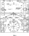
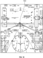
- FIGS. 4 , 6 , 8 , 10 , 12 are diagrams depicting a detected ground object overlaid on a 3-D view in front of an aircraft, with non-linear scaling applied for sizing the ground object.
- FIG. 3 illustrates the display on an SVS display of an example 3-D object 302 that is 50 feet from the view point with only an inverse linear projection function applied for sizing.
- FIG. 4 illustrates the display on an SVS display of the same example 3-D object 402 that is 50 feet from the view point with both an inverse linear projection function and a compensation scaling function applied for sizing.
- the object 402 is displayed smaller than the object 302 since the objects are closer to the aircraft.
- FIG. 5 illustrates the display on an SVS display of an example 3-D object 502 that is 1000 feet from the view point with only an inverse linear projection function applied for sizing.
- FIG. 6 illustrates the display on an SVS display of the same example 3-D object 602 that is 1000 feet from the view point with both an inverse linear projection function and a compensation scaling function applied for sizing.
- the object 502 and 602 are displayed at approximately the same size.
- FIG. 7 illustrates the display on an SVS display of an example 3-D object 702 that is 3000 feet from the view point with only an inverse linear projection function applied for sizing.
- FIG. 8 illustrates the display on an SVS display of the same example 3-D object 802 that is 3000 feet from the view point with both an inverse linear projection function and a compensation scaling function applied for sizing.
- the object 802 is displayed larger than the object 702 since the objects are further away from the aircraft.
- FIG. 9 illustrates the display on an SVS display of an example 3-D object 902 that is 5000 feet from the view point with only an inverse linear projection function applied for sizing.
- FIG. 10 illustrates the display on an SVS display of the same example 3-D object 1002 that is 5000 feet from the view point with both an inverse linear projection function and a compensation scaling function applied for sizing.
- the object 1002 is displayed larger than the object 902 since the objects are further away from the aircraft.
- FIG. 11 illustrates the display on an SVS display of an example 3-D object 1102 that is 7000 feet from the view point with only an inverse linear projection function applied for sizing.
- FIG. 12 illustrates the display on an SVS display of the same example 3-D object 1202 that is 7000 feet from the view point with both an inverse linear projection function and a compensation scaling function applied for sizing.
- the object 1202 is displayed larger than the object 1102 since the objects are further away from the aircraft.
- FIGS. 13A and 14A are diagrams depicting example graphs of scaling factor versus distance of an object to a view point for example compensation scaling functions.
- FIGS. 13B and 14B are diagrams depicting example graphs of display size on screen versus distance of an object to a view point when (i) only an example inverse linear projection is used (at 1312, 1412), (ii) an example inverse linear projection function plus a first example compensation scaling function is used (at 1316, 1416), e.g. , for normal conditions, and (iii) an example inverse linear projection function plus an second example compensation scaling function is used (at 1314, 1414), e.g. , for an alert or bad visual conditions.
- FIGS. 15 and 16 are diagrams depicting a calculated virtual object around the travel path of an aircraft that is overlaid on a 3-D view in front of the aircraft, with non-linear scaling applied for sizing the calculated virtual object.
- FIG. 15 illustrates the display on an SVS display of an example calculated virtual 3-D object 1502 that is in front of the view point with both an inverse linear projection function and a compensation scaling function applied for sizing.
- FIG. 16 illustrates the display on an SVS display of an example calculated virtual 3-D object 1602 that is in front of the view point with both an inverse linear projection function and a compensation scaling function applied for sizing.
- a display system for displaying a three-dimensional view in front of an aerial vehicle.
- the display system comprises a display screen for displaying the three-dimensional view, one or more sensors for obtaining object data regarding objects within the travel path of the aerial vehicle, and a controller for receiving the object data from the one or more sensors and for providing input to the display screen.
- the controller is configured by programming instructions on non-transitory computer readable media to: cause the display of one or more objects as graphical objects in a 3-dimensional graphical representation of real space, wherein the display size of an object is determined based on a non-linear projection per distance between the object and view point that is scaled based on a continuous, non-linear scaling function, which causes the object to be displayed smaller at certain distances and larger at other distances than it would if only linear scaling (e.g., inverse linear scaling performed by an inverse linear function) were applied. This may allow the display size of the object to not be too big when the object is close to the aerial vehicle and to not be too small when the object is far away from the aerial vehicle.
- linear scaling e.g., inverse linear scaling performed by an inverse linear function
- the continuous, non-linear scaling function comprises one of a plurality of different compensation scaling functions.
- the plurality of different compensation scaling functions comprises a first compensation scaling function for normal conditions and a second compensation scaling function for alert or bad visual conditions.
- the first compensation scaling function used to calculate a scaling factor for a specific distance x comprises d 1 (a + (d*x-b)/(e*x+c)), wherein d 1 , a, b, c, d and e are constants and x is the distance from the object to the view point.
- the second compensation scaling function used to calculate a scaling factor for a specific distance x comprises d 2 (a + (d*x-b)/(e*x+c)), wherein d 2 , a, b, c, d and e are constants, d 2 is not equal to d 1 , and x is the distance from the object to the view point.
- d 2 > d 1 , thereby causing the display size of objects at a certain distance to be larger when the second compensation scaling function versus when the first compensation scaling function is used.
- the display size of an object is determined by an inverse linear projection scaling function plus one of the plurality of different compensation scaling functions.
- the inverse linear projection scaling function comprises 1/x, where x is the distance from the object to the view point.
- the display system is a flight deck display system on board an aerial vehicle.
- the flight deck display system comprises a primary flight display (PFD).
- PFD primary flight display
- the display comprises a synthetic vision system displayed on a PFD.
- the display system is further configured to detect a threat level posed by the object and adjust the position of the object on the display based on the determined threat level.
- the system to adjust the position of the object on the display based on the determined threat level, is configured to adjust the position of the object further away from the center of the projected travel path of the aerial vehicle when the threat level is considered low.
- the system to adjust the position of the object on the display based on the determined threat level, is configured to adjust the position of the object closer to the center of the projected travel path of the aerial vehicle when the threat level is considered high.
- the travel path of the aerial vehicle is along a runway and wherein, to adjust the position of the object on the display based on the determined threat level, the system is configured to adjust the position of the object further away from the center of the runway when the threat level is considered low.
- the system to adjust the position of the object on the display based on the determined threat level, is configured to adjust the position of the object closer to the center of the runway when the threat level is considered high.
- a method for displaying objects in the travel path of an aerial vehicle comprises: obtaining object data regarding sensed objects around the travel path of the aerial vehicle from one or more aerial vehicle sensors; determining if the sensed objects are within a field of view of a three-dimensional view in front of the aerial vehicle displayed on a display screen in the aerial vehicle; selecting, for each graphical object representing an object within the field of view of the three-dimensional view, a graphical object display size for the object, wherein the display size of an object is determined based on a non-linear projection per distance between the object and the view point that is scaled based on a continuous, non-linear scaling function, which causes the object to be displayed smaller at certain distances and larger at other distances than it would if only linear scaling (e.g.
- the method further comprises detecting a threat level posed by the object and adjusting the position of the object on the display based on the determined threat level.
- the adjusting comprises adjusting the position of the object further away from the center of the projected travel path of the aerial vehicle when the threat level is considered low.
- the adjusting further comprises adjusting the position of the object closer to the center of the projected travel path of the aerial vehicle when the threat level is considered high.
- the travel path of the aerial vehicle is along a runway and wherein the adjusting further comprises adjusting the position of the object further away from the center of the runway when the threat level is considered low.
- the adjusting further comprises adjusting the position of the object closer to the center of the runway when the threat level is considered high.
- the continuous, non-linear scaling function comprises one of a plurality of different compensation scaling functions.
- the plurality of different compensation scaling functions comprises a first compensation scaling function for normal conditions and a second compensation scaling function for alert or bad visual conditions.
- the first compensation scaling function used to calculate a scaling factor for a specific distance x comprises d 1 (a + (d*x-b)/(e*x+c)), wherein d 1 , a, b, c, d and e are constants and x is the distance from the object to the view point.
- the second compensation scaling function used to calculate a scaling factor for a specific distance x comprises d 2 (a + (d*x-b)/(e*x+c)), wherein d 2 , a, b, c, d and e are constants, d 2 is not equal to d 1 , and x is the distance from the object to the view point.
- d 2 > d 1 thereby causing the display size of objects at a certain distance to be larger when the second compensation scaling function versus when the first compensation scaling function is used.
- the display size of an object is determined by an inverse linear projection scaling function plus one of the plurality of different compensation scaling functions.
- the inverse linear projection scaling function comprises 1/x, where x is the distance from the object to the view point.
- a method for displaying objects in the travel path of an aerial vehicle comprises: obtaining object data regarding a calculated virtual object around the travel path of the aerial vehicle from one or more aerial vehicle sensors; determining if the calculated virtual object is within a field of view of a three-dimensional view in front of the aerial vehicle displayed on a display screen in the aerial vehicle; selecting, for a graphical object representing the calculated virtual object within the field of view of the three-dimensional view, a graphical object display size for the object, wherein the display size of an object is determined based on a non-linear projection per distance between the object and the view point that is scaled based on a continuous, non-linear scaling function, which causes the object to be displayed smaller at certain distances and larger at other distances than it would if only linear scaling (e.g., inverse linear scaling performed by an inverse linear function) were applied, wherein the display size of the object is not too big when the object is nearby the aerial vehicle and not too small when the object is far away; and causing
- the method may further comprise detecting a threat level posed by the object and adjusting the position of the object on the display based on the determined threat level.
- the adjusting may further comprise adjusting the position of the object further away from the center of the projected travel path of the aerial vehicle when the threat level is considered low.
- the adjusting may further comprise adjusting the position of the object closer to the center of the projected travel path of the aerial vehicle when the threat level is considered high.
- the travel path of the aerial vehicle may be along a runway and the adjusting may further comprise adjusting the position of the object further away from the center of the runway when the threat level is considered low.
- the adjusting may further comprise adjusting the position of the object closer to the center of the runway when the threat level is considered high.
- the continuous, non-linear scaling function may comprise one of a plurality of different compensation scaling functions.
- the plurality of different compensation scaling functions may comprise a first compensation scaling function for normal conditions and a second compensation scaling function for alert or bad visual conditions.
- the first compensation scaling function used to calculate a scaling factor for a specific distance x may comprise d 1 (a + (d*x-b)/(e*x+c)), wherein d 1 , a, b, c, d and e are constants and x is the distance from the object to the view point.
- the second compensation scaling function used to calculate a scaling factor for a specific distance x may comprise d 2 (a + (d*x-b)/(e*x+c)), wherein d 2 , a, b, c, d and e are constants, d 2 is not equal to d 1 , and x is the distance from the object to the view point.
- d 2 may be greater d 1 , thereby causing the display size of objects at a certain distance to be larger when the second compensation scaling function versus when the first compensation scaling function is used.
- the display size of an object may be determined by an inverse linear projection scaling function plus one of the plurality of different compensation scaling functions.
- the inverse linear projection scaling function may comprise 1/x, where x is the distance from the object to the view point.
- non-transitory computer readable media encoded with processor executable programming instructions is disclosed.
- a method is performed. The method comprises: obtaining object data regarding sensed objects around the travel path of the aerial vehicle from one or more aerial vehicle sensors; determining if the sensed objects are within a field of view of a three-dimensional view in front of the aerial vehicle displayed on a display screen in the aerial vehicle; selecting, for each graphical object representing an object, a graphical object display size for the object, wherein the display size of an object is determined based on a non-linear projection per distance between the object and the view point that is scaled based on a continuous, non-linear scaling function, which causes the object to be displayed smaller at certain distances and larger at other distances than it would if only linear scaling (e.g., inverse linear scaling performed by an inverse linear function) were applied, wherein the display size of the object is not too big when the object is nearby to the aerial vehicle and not too small when the object
- linear scaling e.g., inverse linear scaling performed
- the method may further comprise detecting a threat level posed by the object and adjusting the position of the object on the display based on the determined threat level.
- the adjusting may further comprise adjusting the position of the object further away from the center of the projected travel path of the aerial vehicle when the threat level is considered low.
- the adjusting may further comprise adjusting the position of the object closer to the center of the projected travel path of the aerial vehicle when the threat level is considered high.
- the travel path of the aerial vehicle may be along a runway and the adjusting may further comprise adjusting the position of the object further away from the center of the runway when the threat level is considered low.
- the adjusting may further comprise adjusting the position of the object closer to the center of the runway when the threat level is considered high.
- the continuous, non-linear scaling function may comprise one of a plurality of different compensation scaling functions.
- the plurality of different compensation scaling functions may comprise a first compensation scaling function for normal conditions and a second compensation scaling function for alert or bad visual conditions.
- the first compensation scaling function used to calculate a scaling factor for a specific distance x may comprise d 1 (a + (d*x-b)/(e*x+c)), wherein d 1 , a, b, c, d and e are constants and x is the distance from the object to the view point.
- the second compensation scaling function used to calculate a scaling factor for a specific distance x may comprise d 2 (a + (d*x-b)/(e*x+c)), wherein d 2 , a, b, c, d and e are constants, d 2 is not equal to d 1 , and x is the distance from the object to the view point.
- d 2 may be greater d 1 , thereby causing the display size of objects at a certain distance to be larger when the second compensation scaling function versus when the first compensation scaling function is used.
- the display size of an object may be determined by an inverse linear projection scaling function plus one of the plurality of different compensation scaling functions.
- the inverse linear projection scaling function may comprise 1/x, where x is the distance from the object to the view point.
- Skilled artisans may implement the described functionality in varying ways for each particular application, but such implementation decisions should not be interpreted as causing a departure from the scope of the present invention.
- an embodiment of a system or a component may employ various integrated circuit components, e.g., memory elements, digital signal processing elements, logic elements, look-up tables, or the like, which may carry out a variety of functions under the control of one or more microprocessors or other control devices.
- integrated circuit components e.g., memory elements, digital signal processing elements, logic elements, look-up tables, or the like, which may carry out a variety of functions under the control of one or more microprocessors or other control devices.
- DSP digital signal processor
- ASIC application specific integrated circuit
- FPGA field programmable gate array
- a general-purpose processor may be a microprocessor, but in the alternative, the processor may be any conventional processor, controller, microcontroller, or state machine.
- a processor may also be implemented as a combination of computing devices, e.g., a combination of a DSP and a microprocessor, a plurality of microprocessors, one or more microprocessors in conjunction with a DSP core, or any other such configuration.
- a software module may reside in RAM memory, flash memory, ROM memory, EPROM memory, EEPROM memory, registers, hard disk, a removable disk, a CD-ROM, or any other form of storage medium known in the art.
- An exemplary storage medium is coupled to the processor such that the processor can read information from, and write information to, the storage medium.
- the storage medium may be integral to the processor.
- the processor and the storage medium may reside in an ASIC.
- the ASIC may reside in a user terminal.
- the processor and the storage medium may reside as discrete components in a user terminal.
Landscapes
- Engineering & Computer Science (AREA)
- Physics & Mathematics (AREA)
- General Physics & Mathematics (AREA)
- Theoretical Computer Science (AREA)
- Aviation & Aerospace Engineering (AREA)
- Computer Hardware Design (AREA)
- Radar, Positioning & Navigation (AREA)
- Remote Sensing (AREA)
- Computing Systems (AREA)
- Geometry (AREA)
- Computer Graphics (AREA)
- Computer Vision & Pattern Recognition (AREA)
- Multimedia (AREA)
- Controls And Circuits For Display Device (AREA)
- Traffic Control Systems (AREA)
Claims (8)
- Anzeigesystem zum Anzeigen einer dreidimensionalen Ansicht vor einem Luftfahrzeug, das Anzeigesystem umfassend:einen Anzeigebildschirm zum Anzeigen der dreidimensionalen Ansicht;einen oder mehrere Sensoren zum Erhalten von Objektdaten in Bezug auf Objekte innerhalb eines Fahrwegs des Luftfahrzeugs,eine Steuerung zum Empfangen der Objektdaten von dem einen oder den mehreren Sensoren und zum Bereitstellen einer Eingabe an den Anzeigebildschirm, wobei die Steuerung durch Programmieranweisungen auf einem nicht flüchtigen computerlesbaren Medium dazu konfiguriert ist,
die Anzeige von einem oder mehreren Objekten als graphische Objekte in einer dreidimensionalen graphischen Darstellung von realem Raum zu veranlassen; wobei die Anzeigegröße eines Objekts auf Basis einer nicht linearen Projektion pro Entfernung zwischen dem Objekt und einem Ansichtspunkt festgelegt wird, die auf Basis einer kontinuierlichen, nicht linearen Skalierfunktion skaliert wird, die das Objekt veranlasst, in bestimmten Entfernungen kleiner und in anderen Entfernungen größer angezeigt zu werden, als dies der Fall wäre, wenn nur eine lineare Skalierung angewendet würde, gekennzeichnet dadurch, dass die kontinuierliche nicht lineare Skalierfunktion eine aus einer Vielzahl von verschiedenen Ausgleichsskalierfunktionen umfasst, welche eine erste Ausgleichsskalierfunktion (1314, 1414) für normale Bedingungen und eine zweite Ausgleichsskalierfunktion (1316, 1416) für Alarmbedingungen oder schlechte Sichtbedingungen umfassen, wobei die Anzeigegröße von Objekten in einer bestimmten Entfernung größer ist, wenn die zweite Ausgleichsskalierfunktion verwendet wird als wenn die erste Ausgleichsskalierfunktion verwendet wird. - Anzeigesystem nach Anspruch 1, wobei die erste Ausgleichsskalierfunktion, die verwendet wird, um einen Skalierfaktor für eine spezifische Entfernung x zu berechnen, d1(a + (d*x-b)/(e*x+c)) umfasst, wobei d1, a, b, c, d und e Konstanten sind und x die Entfernung von dem Objekt zu dem Ansichtspunkt ist.
- Anzeigesystem nach Anspruch 2, wobei die erste Ausgleichsskalierfunktion, die verwendet wird, um einen Skalierfaktor für eine spezifische Entfernung x zu berechnen, d2(a + (d*x-b)/(e*x+c)) umfasst, wobei d2, a, b, c, d und e Konstanten sind, d2 nicht gleich d1 ist und x die Entfernung von dem Objekt zu dem Ansichtspunkt ist und wobei d2 > d1.
- Anzeigesystem nach Anspruch 1, wobei die Anzeigegröße eines Objekts durch eine umgekehrt lineare Projektionsskalierfunktion plus eine aus der Vielzahl von unterschiedlichen Ausgleichsskalierfunktionen ermittelt wird.
- Anzeigesystem nach Anspruch 1, das ferner dazu konfiguriert ist, einen durch das Objekt bestehenden Bedrohungsgrad zu erkennen und die Position des Objekts auf der Anzeige auf Basis des ermittelten Bedrohungsgrades anzupassen.
- Anzeigesystem nach Anspruch 5, wobei das System zum Anpassen der Position des Objekts auf der Anzeige auf Basis des ermittelten Bedrohungsgrades dazu konfiguriert ist,die Position des Objekts weiter weg von der Mitte eines projizierten Fahrweges des Luftfahrzeugs anzupassen, wenn der Bedrohungsgrad für niedrig erachtet wird; unddie Position des Objekts näher zu der Mitte des projizierten Fahrweges des Luftfahrzeugs anzupassen, wenn der Bedrohungsgrad für hoch erachtet wird.
- Anzeigesystem nach Anspruch 6, wobei der Fahrweg des Luftfahrzeugs entlang einer Landebahn ist, und wobei das System zum Anpassen der Position des Objekts auf der Anzeige auf Basis des ermittelten Bedrohungsgrades dazu konfiguriert ist,die Position des Objekts weiter weg von der Mitte der Landebahn anzupassen, wenn der Bedrohungsgrad für niedrig erachtet wird; unddie Position des Objekts näher zu der Mitte der Landebahn anzupassen, wenn der Bedrohungsgrad für hoch erachtet wird.
- Verfahren zum Anzeigen von Objekten in dem Fahrweg eines Luftfahrzeugs, das Verfahren umfassend:Erhalten von Objektdaten in Bezug auf erfasste Objekte um den Fahrweg des Luftfahrzeuges herum von einem oder mehreren Sensoren des Luftfahrzeugs;Ermitteln, ob die erfassten Objekte innerhalb eines Sichtfeldes einer dreidimensionalen Ansicht vor dem Luftfahrzeug liegen, die auf einem Anzeigebildschirm in dem Luftfahrzeug angezeigt wird;Auswählen, für jedes graphische Objekt, das ein Objekt innerhalb des Sichtfelds der dreidimensionalen Ansicht darstellt, einer graphischen Objektanzeigegröße für das Objekt, wobei die Anzeigegröße eines Objekts auf Basis einer nicht linearen Projektion pro Entfernung zwischen dem Objekt und dem Ansichtspunkt ermittelt wird, die auf Basis einer kontinuierlichen, nicht linearen Skalierfunktion skaliert wird, welche das Objekt veranlasst, in bestimmten Entfernungen kleiner und in anderen Entfernungen größer angezeigt zu werden, als dies der Fall wäre, wenn nur lineare Skalierung angewendet würde; undVeranlassen der Anzeige auf dem Anzeigebildschirm des einen oder der mehreren graphischen Objekte mit der ausgewählten Anzeigegröße, gekennzeichnet dadurch, dass die kontinuierliche, nicht lineare Skalierfunktion eine aus einer Vielzahl von unterschiedlichen Ausgleichsskalierfunktionen umfasst, welche eine erste Ausgleichsskalierfunktion (1314, 1414) für normale Bedingungen und eine zweite Ausgleichsskalierfunktion (1316, 1416) für Alarmbedingungen oder schlechte Sichtbedingungen umfassen, wobei die Anzeigegröße des Objekts in einer bestimmten Entfernung größer ist, wenn die zweite Ausgleichsskalierfunktion verwendet wird als wenn die erste Ausgleichsskalierfunktion verwendet wird.
Applications Claiming Priority (2)
| Application Number | Priority Date | Filing Date | Title |
|---|---|---|---|
| US201962861415P | 2019-06-14 | 2019-06-14 | |
| US16/891,660 US11276376B2 (en) | 2019-06-14 | 2020-06-03 | System and method for 3D display of dynamic objects on synthetic vision system in cockpit display system |
Publications (2)
| Publication Number | Publication Date |
|---|---|
| EP3751234A1 EP3751234A1 (de) | 2020-12-16 |
| EP3751234B1 true EP3751234B1 (de) | 2024-10-16 |
Family
ID=71096508
Family Applications (1)
| Application Number | Title | Priority Date | Filing Date |
|---|---|---|---|
| EP20179858.4A Active EP3751234B1 (de) | 2019-06-14 | 2020-06-12 | System und verfahren zur 3d-darstellung von dynamischen objekten auf einem synthetischen sichtsystem in einem cockpitanzeigesystem |
Country Status (2)
| Country | Link |
|---|---|
| US (1) | US11276376B2 (de) |
| EP (1) | EP3751234B1 (de) |
Families Citing this family (2)
| Publication number | Priority date | Publication date | Assignee | Title |
|---|---|---|---|---|
| US11104449B2 (en) * | 2019-01-17 | 2021-08-31 | Honeywell Interntional Inc. | Significant weather advisory system |
| CN112604279A (zh) * | 2020-12-29 | 2021-04-06 | 珠海金山网络游戏科技有限公司 | 一种特效显示方法及装置 |
Family Cites Families (8)
| Publication number | Priority date | Publication date | Assignee | Title |
|---|---|---|---|---|
| US5179377A (en) | 1990-12-31 | 1993-01-12 | Honeywell Inc. | Tcas view display format with horizontal trend |
| US7408552B2 (en) | 2002-02-08 | 2008-08-05 | Raytheon Company | System and method for representation of aircraft altitude using spatial size and other natural perceptual cues |
| US8230359B2 (en) * | 2003-02-25 | 2012-07-24 | Microsoft Corporation | System and method that facilitates computer desktop use via scaling of displayed objects with shifts to the periphery |
| US20090265088A1 (en) | 2007-11-15 | 2009-10-22 | Avidyne Corporation | Symbology for a flight display |
| US8160755B2 (en) | 2008-09-30 | 2012-04-17 | Honeywell International Inc. | Displaying air traffic symbology based on relative importance |
| US8310378B2 (en) * | 2008-10-20 | 2012-11-13 | Honeywell International Inc. | Method and apparatus for displaying prioritized photo realistic features on a synthetic vision system |
| JP2015114249A (ja) * | 2013-12-13 | 2015-06-22 | 国立研究開発法人宇宙航空研究開発機構 | 観測情報処理装置、観測情報処理方法、及び観測情報処理プログラム |
| US9911345B2 (en) | 2016-02-24 | 2018-03-06 | Honeywell International Inc. | System and method for detecting misaligned stationary objects |
-
2020
- 2020-06-03 US US16/891,660 patent/US11276376B2/en active Active
- 2020-06-12 EP EP20179858.4A patent/EP3751234B1/de active Active
Also Published As
| Publication number | Publication date |
|---|---|
| US20200394985A1 (en) | 2020-12-17 |
| EP3751234A1 (de) | 2020-12-16 |
| US11276376B2 (en) | 2022-03-15 |
Similar Documents
| Publication | Publication Date | Title |
|---|---|---|
| EP2778617B1 (de) | Informationsanzeige im Pilotenraum und Systeme und Verfahren zur verbesserten Anzeige von Hindernissen in einer Kombinationsanzeige | |
| KR102796792B1 (ko) | 컨텐츠를 시각화하는 장치 및 방법 | |
| US7286062B2 (en) | Perspective view conformal traffic targets display | |
| EP2835795B1 (de) | System und Verfahren zum Hervorheben eines gefahrenfreien, das Flugzeug umschließenden Bereichs | |
| EP2587222B1 (de) | System zum Anzeigen von Bildern mit Integration von mehreren Auflösungen | |
| US7375678B2 (en) | Displaying obstacles in perspective view | |
| US10963133B2 (en) | Enhanced awareness of obstacle proximity | |
| EP3079138A2 (de) | Flugzeugsysteme und verfahren zum anzeigen einer verbesserten landebahnbeleuchtung | |
| US10431105B2 (en) | Enhanced awareness of obstacle proximity | |
| EP3144637B1 (de) | Verfahren und system zur verbesserung des situationsbewusstseins unvorhergesehener gierbewegung auf einem drehflüglersystem | |
| EP2194361A1 (de) | Systeme und Verfahren zur Verbesserung des Hindernis- und Geländeprofilbewusstseins | |
| EP1959239A1 (de) | System und Verfahren zur Anzeige einer Zielzone | |
| CN105893475B (zh) | 用于在机场移动地图内提高位置感知的系统和方法 | |
| CN105843247B (zh) | 用于显示综合视觉系统视图方向的装置及方法 | |
| US20210020055A1 (en) | Drone detection systems and related presentation methods | |
| US20130179010A1 (en) | System and method for indicating a perspective cockpit field-of-view on a vertical situation display | |
| EP2993656A2 (de) | Systeme und verfahren zur anzeige von daten eines objekts und/oder sich nähernden fahrzeugs innerhalb einer karte mit flughafenbewegungen | |
| EP3751234B1 (de) | System und verfahren zur 3d-darstellung von dynamischen objekten auf einem synthetischen sichtsystem in einem cockpitanzeigesystem | |
| US9950806B2 (en) | Method for displaying an image of a scene outside of an aircraft in an augmented reality context | |
| CN107018356A (zh) | 将来自图像传感器的图像叠加在外部景观的合成第二图像上的图形化表示方法 | |
| US10565882B1 (en) | Vertical situation display past and projected path depiction | |
| EP3767436A1 (de) | Systeme und verfahren zur visualisierung von erweiterter realität basierend auf sensordaten | |
| CN112567259A (zh) | 确定与传感器在机动车辆的环境中检测到的物体关联的置信指数的方法 |
Legal Events
| Date | Code | Title | Description |
|---|---|---|---|
| PUAI | Public reference made under article 153(3) epc to a published international application that has entered the european phase |
Free format text: ORIGINAL CODE: 0009012 |
|
| STAA | Information on the status of an ep patent application or granted ep patent |
Free format text: STATUS: THE APPLICATION HAS BEEN PUBLISHED |
|
| AK | Designated contracting states |
Kind code of ref document: A1 Designated state(s): AL AT BE BG CH CY CZ DE DK EE ES FI FR GB GR HR HU IE IS IT LI LT LU LV MC MK MT NL NO PL PT RO RS SE SI SK SM TR |
|
| AX | Request for extension of the european patent |
Extension state: BA ME |
|
| STAA | Information on the status of an ep patent application or granted ep patent |
Free format text: STATUS: REQUEST FOR EXAMINATION WAS MADE |
|
| 17P | Request for examination filed |
Effective date: 20210615 |
|
| RBV | Designated contracting states (corrected) |
Designated state(s): AL AT BE BG CH CY CZ DE DK EE ES FI FR GB GR HR HU IE IS IT LI LT LU LV MC MK MT NL NO PL PT RO RS SE SI SK SM TR |
|
| RAP3 | Party data changed (applicant data changed or rights of an application transferred) |
Owner name: HONEYWELL INTERNATIONAL INC. |
|
| RIN1 | Information on inventor provided before grant (corrected) |
Inventor name: HE, ZUOWEI Inventor name: HE, GANG Inventor name: FEYEREISEN, THEA |
|
| RAP3 | Party data changed (applicant data changed or rights of an application transferred) |
Owner name: HONEYWELL INTERNATIONAL INC. |
|
| STAA | Information on the status of an ep patent application or granted ep patent |
Free format text: STATUS: EXAMINATION IS IN PROGRESS |
|
| 17Q | First examination report despatched |
Effective date: 20230125 |
|
| P01 | Opt-out of the competence of the unified patent court (upc) registered |
Effective date: 20230421 |
|
| GRAP | Despatch of communication of intention to grant a patent |
Free format text: ORIGINAL CODE: EPIDOSNIGR1 |
|
| STAA | Information on the status of an ep patent application or granted ep patent |
Free format text: STATUS: GRANT OF PATENT IS INTENDED |
|
| INTG | Intention to grant announced |
Effective date: 20240527 |
|
| GRAS | Grant fee paid |
Free format text: ORIGINAL CODE: EPIDOSNIGR3 |
|
| GRAA | (expected) grant |
Free format text: ORIGINAL CODE: 0009210 |
|
| STAA | Information on the status of an ep patent application or granted ep patent |
Free format text: STATUS: THE PATENT HAS BEEN GRANTED |
|
| AK | Designated contracting states |
Kind code of ref document: B1 Designated state(s): AL AT BE BG CH CY CZ DE DK EE ES FI FR GB GR HR HU IE IS IT LI LT LU LV MC MK MT NL NO PL PT RO RS SE SI SK SM TR |
|
| REG | Reference to a national code |
Ref country code: GB Ref legal event code: FG4D |
|
| REG | Reference to a national code |
Ref country code: CH Ref legal event code: EP Ref country code: DE Ref legal event code: R096 Ref document number: 602020039437 Country of ref document: DE |
|
| REG | Reference to a national code |
Ref country code: IE Ref legal event code: FG4D |
|
| REG | Reference to a national code |
Ref country code: LT Ref legal event code: MG9D |
|
| REG | Reference to a national code |
Ref country code: NL Ref legal event code: MP Effective date: 20241016 |
|
| REG | Reference to a national code |
Ref country code: AT Ref legal event code: MK05 Ref document number: 1733242 Country of ref document: AT Kind code of ref document: T Effective date: 20241016 |
|
| PG25 | Lapsed in a contracting state [announced via postgrant information from national office to epo] |
Ref country code: NL Free format text: LAPSE BECAUSE OF FAILURE TO SUBMIT A TRANSLATION OF THE DESCRIPTION OR TO PAY THE FEE WITHIN THE PRESCRIBED TIME-LIMIT Effective date: 20241016 |
|
| PG25 | Lapsed in a contracting state [announced via postgrant information from national office to epo] |
Ref country code: NL Free format text: LAPSE BECAUSE OF FAILURE TO SUBMIT A TRANSLATION OF THE DESCRIPTION OR TO PAY THE FEE WITHIN THE PRESCRIBED TIME-LIMIT Effective date: 20241016 |
|
| PG25 | Lapsed in a contracting state [announced via postgrant information from national office to epo] |
Ref country code: IS Free format text: LAPSE BECAUSE OF FAILURE TO SUBMIT A TRANSLATION OF THE DESCRIPTION OR TO PAY THE FEE WITHIN THE PRESCRIBED TIME-LIMIT Effective date: 20250216 Ref country code: PT Free format text: LAPSE BECAUSE OF FAILURE TO SUBMIT A TRANSLATION OF THE DESCRIPTION OR TO PAY THE FEE WITHIN THE PRESCRIBED TIME-LIMIT Effective date: 20250217 Ref country code: HR Free format text: LAPSE BECAUSE OF FAILURE TO SUBMIT A TRANSLATION OF THE DESCRIPTION OR TO PAY THE FEE WITHIN THE PRESCRIBED TIME-LIMIT Effective date: 20241016 |
|
| PG25 | Lapsed in a contracting state [announced via postgrant information from national office to epo] |
Ref country code: FI Free format text: LAPSE BECAUSE OF FAILURE TO SUBMIT A TRANSLATION OF THE DESCRIPTION OR TO PAY THE FEE WITHIN THE PRESCRIBED TIME-LIMIT Effective date: 20241016 |
|
| PG25 | Lapsed in a contracting state [announced via postgrant information from national office to epo] |
Ref country code: BG Free format text: LAPSE BECAUSE OF FAILURE TO SUBMIT A TRANSLATION OF THE DESCRIPTION OR TO PAY THE FEE WITHIN THE PRESCRIBED TIME-LIMIT Effective date: 20241016 |
|
| PG25 | Lapsed in a contracting state [announced via postgrant information from national office to epo] |
Ref country code: ES Free format text: LAPSE BECAUSE OF FAILURE TO SUBMIT A TRANSLATION OF THE DESCRIPTION OR TO PAY THE FEE WITHIN THE PRESCRIBED TIME-LIMIT Effective date: 20241016 |
|
| PG25 | Lapsed in a contracting state [announced via postgrant information from national office to epo] |
Ref country code: NO Free format text: LAPSE BECAUSE OF FAILURE TO SUBMIT A TRANSLATION OF THE DESCRIPTION OR TO PAY THE FEE WITHIN THE PRESCRIBED TIME-LIMIT Effective date: 20250116 |
|
| PG25 | Lapsed in a contracting state [announced via postgrant information from national office to epo] |
Ref country code: LV Free format text: LAPSE BECAUSE OF FAILURE TO SUBMIT A TRANSLATION OF THE DESCRIPTION OR TO PAY THE FEE WITHIN THE PRESCRIBED TIME-LIMIT Effective date: 20241016 Ref country code: GR Free format text: LAPSE BECAUSE OF FAILURE TO SUBMIT A TRANSLATION OF THE DESCRIPTION OR TO PAY THE FEE WITHIN THE PRESCRIBED TIME-LIMIT Effective date: 20250117 Ref country code: AT Free format text: LAPSE BECAUSE OF FAILURE TO SUBMIT A TRANSLATION OF THE DESCRIPTION OR TO PAY THE FEE WITHIN THE PRESCRIBED TIME-LIMIT Effective date: 20241016 |
|
| PG25 | Lapsed in a contracting state [announced via postgrant information from national office to epo] |
Ref country code: PL Free format text: LAPSE BECAUSE OF FAILURE TO SUBMIT A TRANSLATION OF THE DESCRIPTION OR TO PAY THE FEE WITHIN THE PRESCRIBED TIME-LIMIT Effective date: 20241016 |
|
| PG25 | Lapsed in a contracting state [announced via postgrant information from national office to epo] |
Ref country code: RS Free format text: LAPSE BECAUSE OF FAILURE TO SUBMIT A TRANSLATION OF THE DESCRIPTION OR TO PAY THE FEE WITHIN THE PRESCRIBED TIME-LIMIT Effective date: 20250116 |
|
| PG25 | Lapsed in a contracting state [announced via postgrant information from national office to epo] |
Ref country code: SM Free format text: LAPSE BECAUSE OF FAILURE TO SUBMIT A TRANSLATION OF THE DESCRIPTION OR TO PAY THE FEE WITHIN THE PRESCRIBED TIME-LIMIT Effective date: 20241016 |
|
| PG25 | Lapsed in a contracting state [announced via postgrant information from national office to epo] |
Ref country code: DK Free format text: LAPSE BECAUSE OF FAILURE TO SUBMIT A TRANSLATION OF THE DESCRIPTION OR TO PAY THE FEE WITHIN THE PRESCRIBED TIME-LIMIT Effective date: 20241016 |
|
| REG | Reference to a national code |
Ref country code: DE Ref legal event code: R097 Ref document number: 602020039437 Country of ref document: DE |
|
| PG25 | Lapsed in a contracting state [announced via postgrant information from national office to epo] |
Ref country code: EE Free format text: LAPSE BECAUSE OF FAILURE TO SUBMIT A TRANSLATION OF THE DESCRIPTION OR TO PAY THE FEE WITHIN THE PRESCRIBED TIME-LIMIT Effective date: 20241016 |
|
| PGFP | Annual fee paid to national office [announced via postgrant information from national office to epo] |
Ref country code: FR Payment date: 20250624 Year of fee payment: 6 |
|
| PG25 | Lapsed in a contracting state [announced via postgrant information from national office to epo] |
Ref country code: RO Free format text: LAPSE BECAUSE OF FAILURE TO SUBMIT A TRANSLATION OF THE DESCRIPTION OR TO PAY THE FEE WITHIN THE PRESCRIBED TIME-LIMIT Effective date: 20241016 |
|
| PG25 | Lapsed in a contracting state [announced via postgrant information from national office to epo] |
Ref country code: SK Free format text: LAPSE BECAUSE OF FAILURE TO SUBMIT A TRANSLATION OF THE DESCRIPTION OR TO PAY THE FEE WITHIN THE PRESCRIBED TIME-LIMIT Effective date: 20241016 |
|
| PG25 | Lapsed in a contracting state [announced via postgrant information from national office to epo] |
Ref country code: CZ Free format text: LAPSE BECAUSE OF FAILURE TO SUBMIT A TRANSLATION OF THE DESCRIPTION OR TO PAY THE FEE WITHIN THE PRESCRIBED TIME-LIMIT Effective date: 20241016 |
|
| PG25 | Lapsed in a contracting state [announced via postgrant information from national office to epo] |
Ref country code: IT Free format text: LAPSE BECAUSE OF FAILURE TO SUBMIT A TRANSLATION OF THE DESCRIPTION OR TO PAY THE FEE WITHIN THE PRESCRIBED TIME-LIMIT Effective date: 20241016 |
|
| PLBE | No opposition filed within time limit |
Free format text: ORIGINAL CODE: 0009261 |
|
| STAA | Information on the status of an ep patent application or granted ep patent |
Free format text: STATUS: NO OPPOSITION FILED WITHIN TIME LIMIT |
|
| PG25 | Lapsed in a contracting state [announced via postgrant information from national office to epo] |
Ref country code: SE Free format text: LAPSE BECAUSE OF FAILURE TO SUBMIT A TRANSLATION OF THE DESCRIPTION OR TO PAY THE FEE WITHIN THE PRESCRIBED TIME-LIMIT Effective date: 20241016 |
|
| 26N | No opposition filed |
Effective date: 20250717 |
|
| REG | Reference to a national code |
Ref country code: DE Ref legal event code: R119 Ref document number: 602020039437 Country of ref document: DE |
|
| REG | Reference to a national code |
Ref country code: CH Ref legal event code: H13 Free format text: ST27 STATUS EVENT CODE: U-0-0-H10-H13 (AS PROVIDED BY THE NATIONAL OFFICE) Effective date: 20260127 |
|
| PG25 | Lapsed in a contracting state [announced via postgrant information from national office to epo] |
Ref country code: MC Free format text: LAPSE BECAUSE OF FAILURE TO SUBMIT A TRANSLATION OF THE DESCRIPTION OR TO PAY THE FEE WITHIN THE PRESCRIBED TIME-LIMIT Effective date: 20241016 |
|
| PG25 | Lapsed in a contracting state [announced via postgrant information from national office to epo] |
Ref country code: LU Free format text: LAPSE BECAUSE OF NON-PAYMENT OF DUE FEES Effective date: 20250612 |
|
| GBPC | Gb: european patent ceased through non-payment of renewal fee |
Effective date: 20250612 |
|
| REG | Reference to a national code |
Ref country code: BE Ref legal event code: MM Effective date: 20250630 |
|
| PG25 | Lapsed in a contracting state [announced via postgrant information from national office to epo] |
Ref country code: GB Free format text: LAPSE BECAUSE OF NON-PAYMENT OF DUE FEES Effective date: 20250612 |
|
| PG25 | Lapsed in a contracting state [announced via postgrant information from national office to epo] |
Ref country code: IE Free format text: LAPSE BECAUSE OF NON-PAYMENT OF DUE FEES Effective date: 20250612 Ref country code: DE Free format text: LAPSE BECAUSE OF NON-PAYMENT OF DUE FEES Effective date: 20260101 |
|
| PG25 | Lapsed in a contracting state [announced via postgrant information from national office to epo] |
Ref country code: BE Free format text: LAPSE BECAUSE OF NON-PAYMENT OF DUE FEES Effective date: 20250630 |
|
| PG25 | Lapsed in a contracting state [announced via postgrant information from national office to epo] |
Ref country code: CH Free format text: LAPSE BECAUSE OF NON-PAYMENT OF DUE FEES Effective date: 20250630 |