EP3751177A1 - Work vehicle - Google Patents
Work vehicle Download PDFInfo
- Publication number
- EP3751177A1 EP3751177A1 EP19830725.8A EP19830725A EP3751177A1 EP 3751177 A1 EP3751177 A1 EP 3751177A1 EP 19830725 A EP19830725 A EP 19830725A EP 3751177 A1 EP3751177 A1 EP 3751177A1
- Authority
- EP
- European Patent Office
- Prior art keywords
- oil receiving
- rotating shaft
- receiving part
- transmission
- arm part
- Prior art date
- Legal status (The legal status is an assumption and is not a legal conclusion. Google has not performed a legal analysis and makes no representation as to the accuracy of the status listed.)
- Withdrawn
Links
- 230000005540 biological transmission Effects 0.000 claims abstract description 74
- 230000008878 coupling Effects 0.000 abstract description 40
- 238000010168 coupling process Methods 0.000 abstract description 40
- 238000005859 coupling reaction Methods 0.000 abstract description 40
- 238000003780 insertion Methods 0.000 description 3
- 230000037431 insertion Effects 0.000 description 3
- 239000002994 raw material Substances 0.000 description 3
- 230000033001 locomotion Effects 0.000 description 2
- 238000003754 machining Methods 0.000 description 2
- 238000000034 method Methods 0.000 description 2
- 238000010276 construction Methods 0.000 description 1
- 230000000694 effects Effects 0.000 description 1
- 238000005461 lubrication Methods 0.000 description 1
- 230000003014 reinforcing effect Effects 0.000 description 1
Images




Classifications
-
- B—PERFORMING OPERATIONS; TRANSPORTING
- B60—VEHICLES IN GENERAL
- B60K—ARRANGEMENT OR MOUNTING OF PROPULSION UNITS OR OF TRANSMISSIONS IN VEHICLES; ARRANGEMENT OR MOUNTING OF PLURAL DIVERSE PRIME-MOVERS IN VEHICLES; AUXILIARY DRIVES FOR VEHICLES; INSTRUMENTATION OR DASHBOARDS FOR VEHICLES; ARRANGEMENTS IN CONNECTION WITH COOLING, AIR INTAKE, GAS EXHAUST OR FUEL SUPPLY OF PROPULSION UNITS IN VEHICLES
- B60K17/00—Arrangement or mounting of transmissions in vehicles
- B60K17/04—Arrangement or mounting of transmissions in vehicles characterised by arrangement, location or kind of gearing
- B60K17/06—Arrangement or mounting of transmissions in vehicles characterised by arrangement, location or kind of gearing of change-speed gearing
- B60K17/08—Arrangement or mounting of transmissions in vehicles characterised by arrangement, location or kind of gearing of change-speed gearing of mechanical type
-
- F—MECHANICAL ENGINEERING; LIGHTING; HEATING; WEAPONS; BLASTING
- F16—ENGINEERING ELEMENTS AND UNITS; GENERAL MEASURES FOR PRODUCING AND MAINTAINING EFFECTIVE FUNCTIONING OF MACHINES OR INSTALLATIONS; THERMAL INSULATION IN GENERAL
- F16H—GEARING
- F16H57/00—General details of gearing
- F16H57/04—Features relating to lubrication or cooling or heating
- F16H57/042—Guidance of lubricant
- F16H57/0421—Guidance of lubricant on or within the casing, e.g. shields or baffles for collecting lubricant, tubes, pipes, grooves, channels or the like
- F16H57/0423—Lubricant guiding means mounted or supported on the casing, e.g. shields or baffles for collecting lubricant, tubes or pipes
-
- F—MECHANICAL ENGINEERING; LIGHTING; HEATING; WEAPONS; BLASTING
- F16—ENGINEERING ELEMENTS AND UNITS; GENERAL MEASURES FOR PRODUCING AND MAINTAINING EFFECTIVE FUNCTIONING OF MACHINES OR INSTALLATIONS; THERMAL INSULATION IN GENERAL
- F16H—GEARING
- F16H57/00—General details of gearing
- F16H57/04—Features relating to lubrication or cooling or heating
- F16H57/042—Guidance of lubricant
- F16H57/0421—Guidance of lubricant on or within the casing, e.g. shields or baffles for collecting lubricant, tubes, pipes, grooves, channels or the like
- F16H57/0424—Lubricant guiding means in the wall of or integrated with the casing, e.g. grooves, channels, holes
-
- F—MECHANICAL ENGINEERING; LIGHTING; HEATING; WEAPONS; BLASTING
- F16—ENGINEERING ELEMENTS AND UNITS; GENERAL MEASURES FOR PRODUCING AND MAINTAINING EFFECTIVE FUNCTIONING OF MACHINES OR INSTALLATIONS; THERMAL INSULATION IN GENERAL
- F16H—GEARING
- F16H57/00—General details of gearing
- F16H57/04—Features relating to lubrication or cooling or heating
- F16H57/042—Guidance of lubricant
- F16H57/0432—Lubricant guiding means on or inside shift rods or shift forks
-
- F—MECHANICAL ENGINEERING; LIGHTING; HEATING; WEAPONS; BLASTING
- F16—ENGINEERING ELEMENTS AND UNITS; GENERAL MEASURES FOR PRODUCING AND MAINTAINING EFFECTIVE FUNCTIONING OF MACHINES OR INSTALLATIONS; THERMAL INSULATION IN GENERAL
- F16H—GEARING
- F16H57/00—General details of gearing
- F16H57/04—Features relating to lubrication or cooling or heating
- F16H57/0457—Splash lubrication
-
- F—MECHANICAL ENGINEERING; LIGHTING; HEATING; WEAPONS; BLASTING
- F16—ENGINEERING ELEMENTS AND UNITS; GENERAL MEASURES FOR PRODUCING AND MAINTAINING EFFECTIVE FUNCTIONING OF MACHINES OR INSTALLATIONS; THERMAL INSULATION IN GENERAL
- F16H—GEARING
- F16H57/00—General details of gearing
- F16H57/04—Features relating to lubrication or cooling or heating
- F16H57/0467—Elements of gearings to be lubricated, cooled or heated
- F16H57/0468—Shift rods or shift forks
-
- F—MECHANICAL ENGINEERING; LIGHTING; HEATING; WEAPONS; BLASTING
- F16—ENGINEERING ELEMENTS AND UNITS; GENERAL MEASURES FOR PRODUCING AND MAINTAINING EFFECTIVE FUNCTIONING OF MACHINES OR INSTALLATIONS; THERMAL INSULATION IN GENERAL
- F16H—GEARING
- F16H63/00—Control outputs from the control unit to change-speed- or reversing-gearings for conveying rotary motion or to other devices than the final output mechanism
- F16H63/02—Final output mechanisms therefor; Actuating means for the final output mechanisms
- F16H63/30—Constructional features of the final output mechanisms
- F16H63/32—Gear shift yokes, e.g. shift forks
-
- F—MECHANICAL ENGINEERING; LIGHTING; HEATING; WEAPONS; BLASTING
- F16—ENGINEERING ELEMENTS AND UNITS; GENERAL MEASURES FOR PRODUCING AND MAINTAINING EFFECTIVE FUNCTIONING OF MACHINES OR INSTALLATIONS; THERMAL INSULATION IN GENERAL
- F16H—GEARING
- F16H63/00—Control outputs from the control unit to change-speed- or reversing-gearings for conveying rotary motion or to other devices than the final output mechanism
- F16H63/02—Final output mechanisms therefor; Actuating means for the final output mechanisms
- F16H63/30—Constructional features of the final output mechanisms
- F16H63/32—Gear shift yokes, e.g. shift forks
- F16H2063/321—Gear shift yokes, e.g. shift forks characterised by the interface between fork body and shift rod, e.g. fixing means, bushes, cams or pins
Definitions
- the present invention relates to a work vehicle.
- changes in the transmission gear ratio of a transmission are carried out by using a shift fork to cause a coupling sleeve that moves in the axial direction of an output shaft to mesh with a desired transmission gear.
- Patent Document No. 1 proposes a method for supplying oil to an engagement part between the shift fork and the coupling sleeve by installing an oil receiving part that opens upward in the shift fork so that the oil is supplied from the oil receiving part through a supply channel that passes through the coupling sleeve.
- the oil receiving part captures oil that scatters inside the transmission case.
- Patent Document No. 1 Japanese Unexamined Utility Model Publication Registration Publication No. S54-60167
- An object of the present invention is to provide a transmission that can effectively capture oil while suppressing an increase in the size of the fork, and a work vehicle comprising the transmission.
- a transmission according to the present invention has a rotating shaft, a sleeve configured to rotate around an axial center of the rotating shaft, a fork engaged to an external circumference of the sleeve, and a shift shaft disposed parallel to the rotating shaft and supports the fork.
- the fork includes a support part supported by the shift shaft, a first arm part extending from the support part in a circumferential direction of the rotating shaft and disposed above the sleeve, and an oil receiving part disposed on the first arm part.
- the oil receiving part has an elongated hole that extends in a direction perpendicular to the axial direction of the rotating shaft in a top view.
- a transmission that can effectively capture oil while suppressing an increase in the size of the fork, and a work vehicle comprising the transmission.
- a gearbox that includes a transmission according to the present invention will be explained with reference to the drawings.
- the gearbox that includes the transmission according to the present invention can be applied to various types of vehicles such as a work vehicle (construction vehicle, agricultural vehicle, conveyance vehicle, etc.), an automobile, and a motorcycle or the like, and is especially applicable to a work vehicle.
- a work vehicle construction vehicle, agricultural vehicle, conveyance vehicle, etc.
- an automobile and a motorcycle or the like
- “up” and “down” are terms based on the vertical direction.
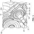
- FIG. 1 and 2 are perspective views illustrating an internal structure of a gearbox 100 according to the present embodiment. Configuration elements are omitted as appropriate in order to illustrate the main parts of the present invention in FIG. 1 and 2 .
- the gearbox 100 is provided with a transmission case 10 and a transmission 20.
- the transmission case 10 contains the transmission 20. Oil is accumulated inside the transmission case 10 up to a predetermined height. A portion of the transmission 20 is immersed in the oil accumulated in the transmission case 10. The oil accumulated in the transmission case 10 scatters inside the case due to the motion of the transmission 20 whereby oil is supplied to the entire transmission 20.
- the transmission case 10 has a first inner wall 11 and a second inner wall 12.
- the first inner wall 11 extends in the vertical direction.
- the second inner wall 12 adjoins the first inner wall 11 at the bottom end.
- the second inner wall 12 is inclined with respect to the first inner wall 11.
- a border portion 13 between the first inner wall 11 and the second inner wall 12 is shaped in a convex shape that protrudes toward the inside of the transmission case 10.
- An oil receiving part 33 of a belowmentioned shift fork 24 is disposed below the border portion 13. Consequently, oil that drips down from the vicinity of the border portion 13 is effectively captured by the oil receiving part 33 disposed below the border portion 13.
- the oil receiving part 33 may also capture oil scattered inside the transmission case 10 in addition to the oil that drips down from the vicinity of the border portion 13.
- the transmission 20 is provided with a rotating shaft 21, a synchronizer hub 22, a coupling sleeve 23 (example of a "sleeve”), the shift fork 24 (example of a "fork”), and a shift shaft 25.
- the rotating shaft 21 is an output shaft of the transmission 20.
- the rotating shaft 21 extends in the horizontal direction.
- the synchronizer hub 22 is an annular member that surrounds the rotating shaft 21.
- the synchronizer hub 22 is fixed to the rotating shaft 21 with a spline fitting, for example. Teeth 22a are formed on the external circumferential surface of the synchronizer hub 22.
- the coupling sleeve 23 is an annular member that surrounds the synchronizer hub 22. Teeth 23a are formed on the internal circumferential surface of the coupling sleeve 23. The teeth 23a of the coupling sleeve 23 mesh with the teeth 22a of the synchronizer hub 22.
- FIG. 3 is a cross-partal view of the transmission 20 parallel to the rotating shaft 21.
- transmission gears 26 and 27 are disposed on either side of the coupling sleeve 23 in the axial direction of the rotating shaft 21.
- the transmission gears 26 and 27 are loosely fitted to the rotating shaft 21.
- the coupling sleeve 23 moves toward the transmission gear 26 in the axial direction of the rotating shaft 21, and when the coupling sleeve 23 synchronizes with the transmission gear 26, the rotation of the transmission gear 26 is transmitted to the synchronizer hub 22 through the coupling sleeve 23. As a result, the rotating shaft 21 rotates.
- the coupling sleeve 23 moves toward the transmission gear 27 in the axial direction of the rotating shaft 21 and, when the coupling sleeve 23 synchronizes with the transmission gear 27, the rotation of the transmission gear 27 is transmitted to the synchronizer hub 22 through the coupling sleeve 23, whereby the rotating shaft 21 rotates.
- the shift fork 24 is an annular member that surrounds the coupling sleeve 23.
- the shift fork 24 is fixed to the shift shaft 25.
- the shift fork 24 is a member for moving the coupling sleeve 23 in the axial direction of the rotating shaft 21.
- the shift fork 24 engages with an engagement groove 23b (see FIG. 3 ) formed on the external circumference of the coupling sleeve 23. While the coupling sleeve 23 is a rotating member, the shift fork 24 is a nonrotating member. When the coupling sleeve 23 rotates in synchronization with the transmission gears 26 and 27, the coupling sleeve 23 slides against the shift fork 24.
- the shift fork 24 As illustrated in FIG. 3 , the shift fork 24 according to the present embodiment is disposed between the transmission gears 26 and 27 in the axial direction of the rotating shaft 21. Therefore, the movement range of the shift fork 24 is restricted by the transmission gears 26 and 27.
- the outer diameter of the shift fork 24 is smaller than the outer diameter of the transmission gear 26 which is larger than the transmission gear 27 in the radial direction perpendicular to the axial direction of the rotating shaft 21. In this way, since the shift fork 24 does not protrude beyond the transmission gear 26, the size of the transmission 20 can be reduced.
- the outer diameter of the transmission gear 27 is larger than the outer diameter of the shift fork 24 in the radial direction, the outer diameter of the shift fork 24 may be equal to or smaller than the outer diameter of the transmission gear 27.
- the shift shaft 25 supports the shift fork 24.
- the shift shaft 25 is disposed parallel to the rotating shaft 21.
- the shift shaft 25 is able to move in the axial direction of the rotating shaft 21.
- the shift shaft 25 is moved in the axial direction in response to a shift change operation by an operator. As a result, the shift fork 24 moves in the axial direction of the rotating shaft 21.
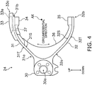
- FIG. 4 is a side view of the shift fork 24 as seen from the axial direction of the rotating shaft 21.
- FIG. 5 is a perspective view of the shift fork 24 as seen from above.
- FIG. 6 is a perspective view of the shift fork 24 as seen from below.
- the shift fork 24 has a support part 30, a first arm part 31, a second arm part 32, the oil receiving part 33, a first pawl part 34, a second pawl part 35, a rib 36, and an oil supply hole 37.
- the support part 30 is disposed between the first arm part 31 and the second arm part 32.
- the support part 30 has an insertion hole 30a.
- the shift shaft 25 illustrated in FIG. 1 is inserted into the insertion hole 30a.
- the support part 30 is supported by and fixed to the shift shaft 25 inserted into the insertion hole 30a.
- the supporting force for supporting the shift fork 24 acts only on the shift shaft 25 and the support part 30.
- the function for supporting the shift fork 24 is assumed only by the support part 30, and the first and second arm parts 31 and 32 do not assume the role of supporting the shift fork 24. Therefore, it can be said that the location where the supporting force acts within the shift fork 24 is the support part 30 and the locations where the supporting force does not act is the first and second arm parts 31 and 32.
- the first arm part 31 extends from the support part 30 in the circumferential direction centered on the axial center AX of the rotating shaft 21.
- the first arm part 31 extends obliquely upward from the support part 30.
- a base end portion 31a connected to the support part 30 within the first arm part 31 is a fixed end portion, and a tip end portion 31b on the opposite side from the support part 30 is a free end portion.
- the first arm part 31 is disposed above the coupling sleeve 23 as illustrated in FIG. 1 .
- the overall length of the first arm part 31 may be changed as appropriate.
- the first arm part 31 has an internal circumferential surface 31S and an external circumferential surface 31T.
- the internal circumferential surface 31S faces the coupling sleeve 23 as illustrated in FIG. 1 .
- the external circumferential surface 31T is provided on the opposite side of the internal circumferential surface 31S.
- the internal circumferential surface 31S and the external circumferential surface 31T both extend in the circumferential direction.
- the second arm part 32 extends from the support part 30 in the circumferential direction centered on the axial center AX of the rotating shaft 21.
- the second arm part 32 extends obliquely downward from the support part 30.
- a base end portion 32a connected to the support part 30 within the second arm part 32 is a fixed end portion, and a tip end portion 32b on the opposite side from the support part 30 is a free end portion.
- the second arm part 32 is disposed below the coupling sleeve 23 illustrated in FIG. 1 .
- the overall length of the second arm part 32 may be changed as appropriate.
- the second arm part 32 has an internal circumferential surface 32S and an external circumferential surface 32T.
- the internal circumferential surface 32S faces the coupling sleeve 23 as illustrated in FIG. 2 .
- the external circumferential surface 32T is provided on the opposite side of the internal circumferential surface 32S.
- the internal circumferential surface 32S and the external circumferential surface 32T both extend in the circumferential direction.
- the oil receiving part 33 is disposed on the first arm part 31.
- the oil receiving part 33 is disposed on the external circumferential surface 31T of the first arm part 31.
- FIG. 7 is a top view illustrating the shift fork 24 from above in the vertical direction.
- the oil receiving part 33 has an elongated hole 33a that extends in a direction (referred to below as "perpendicular direction") perpendicular to the axial direction of the rotating shaft as seen in the top view.
- the elongated hole 33a is formed on an upper surface 33b of the oil receiving part 33.
- the elongated hole 33a opens upward.
- the elongated hole 33a captures oil that drips down from the vicinity of the border portion 13 of the first inner wall 11 and the second inner wall 12 illustrated in FIG. 1 , and oil that scatters inside the transmission case 10.
- the elongated hole 33a collects the captured oil.
- the oil collected in the elongated hole 33a is supplied to the external circumferential surface of the coupling sleeve 23 via the oil supply hole 37.
- the length La of the elongated hole 33a in the perpendicular direction is greater than the maximum width Wa of the elongated hole 33a in the axial direction of the rotating shaft 21. Therefore, lubrication of the coupling sleeve 23 can be maintained as desired since both the oil that drips down from the vicinity of the border portion 13 and the oil that scatters inside the transmission case 10 can be effectively captured.
- the length La of the elongated hole 33a is preferably 1.5 times or more the width Wa, and more preferably 2.0 times or more. As a result thereof, the capture efficiency of oil by the elongated hole 33a can be further improved.
- a first side surface 33p of the oil receiving part 33 smoothly joins a first side surface 31p of the first arm part 31.
- No curved step is provided between the first side surface 33p of the oil receiving part 33 and the first side surface 31p of the first arm part 31.
- the first side surface 33p of the oil receiving part 33 is roughly flush with the first side surface 31p of the first arm part 31.
- a second side surface 33q of the oil receiving part 33 joins smoothly with a second side surface 31q of the first arm part 31.
- No curved step is provided between the second side surface 33q of the oil receiving part 33 and the second side surface 31q of the first arm part 31.
- the second side surface 33q of the oil receiving part 33 is roughly flush with the second side surface 31q of the first arm part 31.
- the oil receiving part 33 is disposed on the tip end portion 31b of the first arm part 31.
- a tip end portion 33c of the oil receiving part 33 protrudes further than the tip end portion 31b of the first arm part 31 in the circumferential direction.
- the protruding length of the tip end portion 33c of the oil receiving part 33 in the circumferential direction from the tip end portion 31b of the first arm part 31 may be changed as appropriate.
- the oil receiving part 33 is positioned above a pawl part 34 in the vertical direction. Therefore, the oil receiving part 33 overlaps the pawl part 34 in the vertical direction. In the present embodiment, only a portion of the oil receiving part 33 overlaps the pawl part 34 in the vertical direction. The length in the perpendicular direction that the oil receiving part 33 overlaps the pawl part 34 may be changed as appropriate.
- the tip end portion 33c of the oil receiving part 33 protrudes further than the pawl part 34 in the circumferential direction.
- the length that the tip end portion 33c of the oil receiving part 33 protrudes from the pawl part 34 in the circumferential direction may be changed as appropriate.
- the oil receiving part 33 is formed integrally with the first arm part 31.
- the first arm part 31 and the oil receiving part 33 can be made integrally by machining a forged raw material component for the shift fork 24.
- the first pawl part 34 is disposed on the internal circumferential surface 31S of the first arm part 31.
- the second pawl part 35 is disposed on the internal circumferential surface 32S of the second arm part 32.
- the first pawl part 34 and the second pawl part 35 are both engaged to the engagement groove 23b of the coupling sleeve 23 illustrated in FIG. 3 .
- the rib 36 is disposed so as to cross from the internal circumferential surface 31S of the first arm part 31 to the internal circumferential surface 32S of the second arm part 32.
- the rib 36 is disposed so as to join the first pawl part 34 and the second pawl part 35.
- the rib 36 is a member for reinforcing the shift fork 24.
- the oil supply hole 37 communicates between the bottom surface of the elongated hole 33a formed in the oil receiving part 33 and the internal circumferential surface 31S of the first arm part 31.
- the oil supply hole 37 supplies oil collected in the elongated hole 33a to the external circumferential surface of the coupling sleeve 23.
- FIG. 8 is a development view illustrating the external circumferential surface of the shift fork 24 developed in a plan view.
- the maximum width W33 of the oil receiving part 33 in the axial direction of the rotating shaft 21 is equal to or less than the maximum width W31 of the first arm part 31.
- the maximum width W33 of the oil receiving part 33 is roughly the same as the maximum width W31 of the first arm part 31, the maximum width W33 may be smaller than the maximum width W31 of the first arm part 31.
- the maximum width W33 of the oil receiving part 33 in the axial direction of the rotating shaft 21 is equal to or less than the maximum width W23 (not illustrated in FIG. 8 ; see FIG. 3 ) of the coupling sleeve 23.
- the maximum width W33 of the oil receiving part 33 is roughly the same as the maximum width W23 of the coupling sleeve 23, the maximum width W33 may be smaller than the maximum width W23 of the coupling sleeve 23.
- the average width W24 of the entire shift fork 24 in the axial direction of the rotating shaft 21 is smaller than ⁇ 10% of the maximum width W33 of the oil receiving part 33 and larger than the maximum width Wa of the elongated hole 33a.
- the average width W24 of the entire shift fork 24 is calculated by measuring the intervals between two straight lines obtained by performing collinear approximation with the least-squares method on both end sides of the shift fork 24 in the axial direction, at ten points derived by dividing the entire length of the shift fork 24 in a direction perpendicular to the axial direction into 11 equal parts, and then deriving the arithmetical mean of the measured values.
- the ⁇ 10% of the maximum width W33 of the oil receiving part 33 signifies a range of 0.9 to 1.1 times the maximum width W33. Imparting the range to the maximum width W33 of the oil receiving part 33 in this way takes into account the case of a gradient being unavoidably provided to the forged raw material component for the shift fork 24, and the case of a step being unavoidably provided between the oil receiving part 33 and the first arm part 31 when machining the raw material component.
- the shift fork 24 has the oil receiving part 33 disposed on the first arm part 31.
- the oil receiving part 33 has an elongated hole 33a that extends in a direction perpendicular to the axial center AX of the rotating shaft 21 as seen in the top view. Therefore, oil dripping down from the inner wall of the transmission case 10 and oil scattering inside the transmission case 10 can be effectively captured while suppressing an increase in the size of the shift fork.
- the maximum width W33 of the oil receiving part 33 in the axial direction of the rotating shaft 21 is equal to or less than the maximum width W31 of the first arm part 31. Therefore, the shift fork 24 can be made more compact in the axial direction.
- the maximum width W33 of the oil receiving part 33 in the axial direction of the rotating shaft 21 is equal to or less than the maximum width W23 of the coupling sleeve 23. Therefore, the size of the transmission 20 can be reduced by making the gap between the transmission gears 26 and 27 narrower since interference between the transmission gears 26 and 27 disposed on both sides of the coupling sleeve 23, and the oil receiving part 33 can be suppressed.
- the average width W24 of the entire shift fork 24 in the axial direction of the rotating shaft 21 is smaller than ⁇ 10% of the maximum width W33 of the oil receiving part 33 and larger than the maximum width Wa of the elongated hole 33a. Therefore, the shift fork 24 can be made more compact overall in the axial direction.
- the tip end portion 33c of the oil receiving part 33 protrudes further than the pawl part 34 in the circumferential direction. Therefore, the capture efficiency of oil by the elongated hole 33a can be further improved by increasing the length La of the elongated hole 33a.
- the tip end portion 33c of the oil receiving part 33 protrudes further than the tip end portion 31b of the first arm part 31 in the circumferential direction. Therefore, the capture efficiency of oil by the elongated hole 33a can be further improved by increasing the length La of the elongated hole 33a.
- the position of the oil receiving part 33 may be changed as appropriate.
- oil receiving part 33 is formed integrally with the first arm part 31 in the above embodiment, the oil receiving part 33 may be formed separately from the first arm part 31.
- the oil receiving part 33 is disposed below the border portion 13 of the first inner wall 11 and the second inner wall 12 in the above embodiment, the oil receiving part 33 may be disposed in a position offset from below the border portion 13. In the above case, oil can be captured effectively since the elongated hole 33a is provided in the oil receiving part 33.
Landscapes
- Engineering & Computer Science (AREA)
- General Engineering & Computer Science (AREA)
- Mechanical Engineering (AREA)
- Chemical & Material Sciences (AREA)
- Combustion & Propulsion (AREA)
- Transportation (AREA)
- General Details Of Gearings (AREA)
- Gear-Shifting Mechanisms (AREA)
Abstract
Description
- The present invention relates to a work vehicle.
- In general, changes in the transmission gear ratio of a transmission are carried out by using a shift fork to cause a coupling sleeve that moves in the axial direction of an output shaft to mesh with a desired transmission gear.
- Patent Document No. 1 proposes a method for supplying oil to an engagement part between the shift fork and the coupling sleeve by installing an oil receiving part that opens upward in the shift fork so that the oil is supplied from the oil receiving part through a supply channel that passes through the coupling sleeve. The oil receiving part captures oil that scatters inside the transmission case.
- Patent Document No. 1: Japanese Unexamined Utility Model Publication Registration Publication No.
S54-60167 - There is a desire to effectively capture oil with the oil receiving part while suppressing an increase in the size of the fork.
- An object of the present invention is to provide a transmission that can effectively capture oil while suppressing an increase in the size of the fork, and a work vehicle comprising the transmission.
- A transmission according to the present invention has a rotating shaft, a sleeve configured to rotate around an axial center of the rotating shaft, a fork engaged to an external circumference of the sleeve, and a shift shaft disposed parallel to the rotating shaft and supports the fork. The fork includes a support part supported by the shift shaft, a first arm part extending from the support part in a circumferential direction of the rotating shaft and disposed above the sleeve, and an oil receiving part disposed on the first arm part. The oil receiving part has an elongated hole that extends in a direction perpendicular to the axial direction of the rotating shaft in a top view.
- According to the present invention, there is provided a transmission that can effectively capture oil while suppressing an increase in the size of the fork, and a work vehicle comprising the transmission.
-
-
FIG. 1 is a perspective view illustrating an internal structure of a transmission device. -
FIG. 2 is a perspective view illustrating an internal structure of the transmission device. -
FIG. 3 is a cross-partal view of atransmission 20 parallel to a rotating shaft. -
FIG. 4 is a side view of a shift fork seen from the axial direction of the rotating shaft. -
FIG. 5 is a perspective view of the shift fork seen from above. -
FIG. 6 is a perspective view of the shift fork seen from below. -
FIG. 7 is a top view of the shift fork. -
FIG. 8 is a development view of the external circumferential surface of the shift fork. - A gearbox that includes a transmission according to the present invention will be explained with reference to the drawings. The gearbox that includes the transmission according to the present invention can be applied to various types of vehicles such as a work vehicle (construction vehicle, agricultural vehicle, conveyance vehicle, etc.), an automobile, and a motorcycle or the like, and is especially applicable to a work vehicle. In the present embodiment, "up" and "down" are terms based on the vertical direction.
-
FIG. 1 and2 are perspective views illustrating an internal structure of agearbox 100 according to the present embodiment. Configuration elements are omitted as appropriate in order to illustrate the main parts of the present invention inFIG. 1 and2 . - The
gearbox 100 is provided with atransmission case 10 and atransmission 20. - The
transmission case 10 contains thetransmission 20. Oil is accumulated inside thetransmission case 10 up to a predetermined height. A portion of thetransmission 20 is immersed in the oil accumulated in thetransmission case 10. The oil accumulated in thetransmission case 10 scatters inside the case due to the motion of thetransmission 20 whereby oil is supplied to theentire transmission 20. - As illustrated in
FIG. 2 , thetransmission case 10 has a firstinner wall 11 and a secondinner wall 12. The firstinner wall 11 extends in the vertical direction. The secondinner wall 12 adjoins the firstinner wall 11 at the bottom end. The secondinner wall 12 is inclined with respect to the firstinner wall 11. Aborder portion 13 between the firstinner wall 11 and the secondinner wall 12 is shaped in a convex shape that protrudes toward the inside of thetransmission case 10. - Oil that scatters inside the
transmission case 10 and adheres to the firstinner wall 11 flows downward along the firstinner wall 11 and then falls downward from the vicinity of theborder portion 13. Anoil receiving part 33 of abelowmentioned shift fork 24 is disposed below theborder portion 13. Consequently, oil that drips down from the vicinity of theborder portion 13 is effectively captured by theoil receiving part 33 disposed below theborder portion 13. Theoil receiving part 33 may also capture oil scattered inside thetransmission case 10 in addition to the oil that drips down from the vicinity of theborder portion 13. - The
transmission 20 is provided with arotating shaft 21, asynchronizer hub 22, a coupling sleeve 23 (example of a "sleeve"), the shift fork 24 (example of a "fork"), and ashift shaft 25. - The rotating
shaft 21 is an output shaft of thetransmission 20. In the present embodiment, therotating shaft 21 extends in the horizontal direction. Thesynchronizer hub 22 is an annular member that surrounds therotating shaft 21. Thesynchronizer hub 22 is fixed to the rotatingshaft 21 with a spline fitting, for example. Teeth 22a are formed on the external circumferential surface of thesynchronizer hub 22. - The
coupling sleeve 23 is an annular member that surrounds thesynchronizer hub 22. Teeth 23a are formed on the internal circumferential surface of thecoupling sleeve 23. Theteeth 23a of the coupling sleeve 23 mesh with theteeth 22a of thesynchronizer hub 22. -
FIG. 3 is a cross-partal view of thetransmission 20 parallel to the rotatingshaft 21. - As illustrated in
FIG. 3 ,transmission gears coupling sleeve 23 in the axial direction of the rotatingshaft 21. Thetransmission gears shaft 21. Thecoupling sleeve 23 moves toward thetransmission gear 26 in the axial direction of the rotatingshaft 21, and when thecoupling sleeve 23 synchronizes with thetransmission gear 26, the rotation of thetransmission gear 26 is transmitted to thesynchronizer hub 22 through thecoupling sleeve 23. As a result, therotating shaft 21 rotates. Similarly, thecoupling sleeve 23 moves toward thetransmission gear 27 in the axial direction of the rotatingshaft 21 and, when thecoupling sleeve 23 synchronizes with thetransmission gear 27, the rotation of thetransmission gear 27 is transmitted to thesynchronizer hub 22 through thecoupling sleeve 23, whereby the rotatingshaft 21 rotates. - The
shift fork 24 is an annular member that surrounds thecoupling sleeve 23. Theshift fork 24 is fixed to theshift shaft 25. Theshift fork 24 is a member for moving thecoupling sleeve 23 in the axial direction of therotating shaft 21. Theshift fork 24 engages with anengagement groove 23b (seeFIG. 3 ) formed on the external circumference of thecoupling sleeve 23. While thecoupling sleeve 23 is a rotating member, theshift fork 24 is a nonrotating member. When thecoupling sleeve 23 rotates in synchronization with the transmission gears 26 and 27, thecoupling sleeve 23 slides against theshift fork 24. - As illustrated in
FIG. 3 , theshift fork 24 according to the present embodiment is disposed between the transmission gears 26 and 27 in the axial direction of therotating shaft 21. Therefore, the movement range of theshift fork 24 is restricted by the transmission gears 26 and 27. The outer diameter of theshift fork 24 is smaller than the outer diameter of thetransmission gear 26 which is larger than thetransmission gear 27 in the radial direction perpendicular to the axial direction of therotating shaft 21. In this way, since theshift fork 24 does not protrude beyond thetransmission gear 26, the size of thetransmission 20 can be reduced. - In the present embodiment, while the outer diameter of the
transmission gear 27 is larger than the outer diameter of theshift fork 24 in the radial direction, the outer diameter of theshift fork 24 may be equal to or smaller than the outer diameter of thetransmission gear 27. - The
shift shaft 25 supports theshift fork 24. Theshift shaft 25 is disposed parallel to therotating shaft 21. Theshift shaft 25 is able to move in the axial direction of therotating shaft 21. Theshift shaft 25 is moved in the axial direction in response to a shift change operation by an operator. As a result, theshift fork 24 moves in the axial direction of therotating shaft 21. - A configuration of the
shift fork 24 will be explained with reference to the drawings.FIG. 4 is a side view of theshift fork 24 as seen from the axial direction of therotating shaft 21.FIG. 5 is a perspective view of theshift fork 24 as seen from above.FIG. 6 is a perspective view of theshift fork 24 as seen from below. - The
shift fork 24 has asupport part 30, afirst arm part 31, asecond arm part 32, theoil receiving part 33, afirst pawl part 34, asecond pawl part 35, arib 36, and anoil supply hole 37. - The
support part 30 is disposed between thefirst arm part 31 and thesecond arm part 32. Thesupport part 30 has aninsertion hole 30a. Theshift shaft 25 illustrated inFIG. 1 is inserted into theinsertion hole 30a. Thesupport part 30 is supported by and fixed to theshift shaft 25 inserted into theinsertion hole 30a. In the present embodiment, the supporting force for supporting theshift fork 24 acts only on theshift shaft 25 and thesupport part 30. The function for supporting theshift fork 24 is assumed only by thesupport part 30, and the first andsecond arm parts shift fork 24. Therefore, it can be said that the location where the supporting force acts within theshift fork 24 is thesupport part 30 and the locations where the supporting force does not act is the first andsecond arm parts - The
first arm part 31 extends from thesupport part 30 in the circumferential direction centered on the axial center AX of therotating shaft 21. Thefirst arm part 31 extends obliquely upward from thesupport part 30. Abase end portion 31a connected to thesupport part 30 within thefirst arm part 31 is a fixed end portion, and atip end portion 31b on the opposite side from thesupport part 30 is a free end portion. - The
first arm part 31 is disposed above thecoupling sleeve 23 as illustrated inFIG. 1 . In the present embodiment, while thefirst arm part 31 covers around one quarter of the external circumference of thecoupling sleeve 23, the overall length of thefirst arm part 31 may be changed as appropriate. - The
first arm part 31 has an internalcircumferential surface 31S and an externalcircumferential surface 31T. The internalcircumferential surface 31S faces thecoupling sleeve 23 as illustrated inFIG. 1 . The externalcircumferential surface 31T is provided on the opposite side of the internalcircumferential surface 31S. The internalcircumferential surface 31S and the externalcircumferential surface 31T both extend in the circumferential direction. - The
second arm part 32 extends from thesupport part 30 in the circumferential direction centered on the axial center AX of therotating shaft 21. Thesecond arm part 32 extends obliquely downward from thesupport part 30. Abase end portion 32a connected to thesupport part 30 within thesecond arm part 32 is a fixed end portion, and atip end portion 32b on the opposite side from thesupport part 30 is a free end portion. - The
second arm part 32 is disposed below thecoupling sleeve 23 illustrated inFIG. 1 . In the present embodiment, while thesecond arm part 32 covers around one quarter of the external circumference of thecoupling sleeve 23, the overall length of thesecond arm part 32 may be changed as appropriate. - The
second arm part 32 has an internalcircumferential surface 32S and an externalcircumferential surface 32T. The internalcircumferential surface 32S faces thecoupling sleeve 23 as illustrated inFIG. 2 . The externalcircumferential surface 32T is provided on the opposite side of the internalcircumferential surface 32S. The internalcircumferential surface 32S and the externalcircumferential surface 32T both extend in the circumferential direction. - The
oil receiving part 33 is disposed on thefirst arm part 31. Theoil receiving part 33 is disposed on the externalcircumferential surface 31T of thefirst arm part 31. -
FIG. 7 is a top view illustrating theshift fork 24 from above in the vertical direction. Theoil receiving part 33 has anelongated hole 33a that extends in a direction (referred to below as "perpendicular direction") perpendicular to the axial direction of the rotating shaft as seen in the top view. Theelongated hole 33a is formed on anupper surface 33b of theoil receiving part 33. Theelongated hole 33a opens upward. Theelongated hole 33a captures oil that drips down from the vicinity of theborder portion 13 of the firstinner wall 11 and the secondinner wall 12 illustrated inFIG. 1 , and oil that scatters inside thetransmission case 10. Theelongated hole 33a collects the captured oil. The oil collected in theelongated hole 33a is supplied to the external circumferential surface of thecoupling sleeve 23 via theoil supply hole 37. - As seen in the top view, the length La of the
elongated hole 33a in the perpendicular direction is greater than the maximum width Wa of theelongated hole 33a in the axial direction of therotating shaft 21. Therefore, lubrication of thecoupling sleeve 23 can be maintained as desired since both the oil that drips down from the vicinity of theborder portion 13 and the oil that scatters inside thetransmission case 10 can be effectively captured. - The length La of the
elongated hole 33a is preferably 1.5 times or more the width Wa, and more preferably 2.0 times or more. As a result thereof, the capture efficiency of oil by theelongated hole 33a can be further improved. - In the top view, a
first side surface 33p of theoil receiving part 33 smoothly joins afirst side surface 31p of thefirst arm part 31. No curved step is provided between thefirst side surface 33p of theoil receiving part 33 and thefirst side surface 31p of thefirst arm part 31. In the present embodiment, thefirst side surface 33p of theoil receiving part 33 is roughly flush with thefirst side surface 31p of thefirst arm part 31. - Similarly, in the top view, a second side surface 33q of the
oil receiving part 33 joins smoothly with a second side surface 31q of thefirst arm part 31. No curved step is provided between the second side surface 33q of theoil receiving part 33 and the second side surface 31q of thefirst arm part 31. In the present embodiment, the second side surface 33q of theoil receiving part 33 is roughly flush with the second side surface 31q of thefirst arm part 31. - As illustrated in
FIG. 4-6 , theoil receiving part 33 is disposed on thetip end portion 31b of thefirst arm part 31. Atip end portion 33c of theoil receiving part 33 protrudes further than thetip end portion 31b of thefirst arm part 31 in the circumferential direction. The protruding length of thetip end portion 33c of theoil receiving part 33 in the circumferential direction from thetip end portion 31b of thefirst arm part 31 may be changed as appropriate. - The
oil receiving part 33 is positioned above apawl part 34 in the vertical direction. Therefore, theoil receiving part 33 overlaps thepawl part 34 in the vertical direction. In the present embodiment, only a portion of theoil receiving part 33 overlaps thepawl part 34 in the vertical direction. The length in the perpendicular direction that theoil receiving part 33 overlaps thepawl part 34 may be changed as appropriate. - The
tip end portion 33c of theoil receiving part 33 protrudes further than thepawl part 34 in the circumferential direction. The length that thetip end portion 33c of theoil receiving part 33 protrudes from thepawl part 34 in the circumferential direction may be changed as appropriate. - In the present embodiment, the
oil receiving part 33 is formed integrally with thefirst arm part 31. Thefirst arm part 31 and theoil receiving part 33 can be made integrally by machining a forged raw material component for theshift fork 24. - As illustrated in
FIG. 4-6 , thefirst pawl part 34 is disposed on the internalcircumferential surface 31S of thefirst arm part 31. Thesecond pawl part 35 is disposed on the internalcircumferential surface 32S of thesecond arm part 32. Thefirst pawl part 34 and thesecond pawl part 35 are both engaged to theengagement groove 23b of thecoupling sleeve 23 illustrated inFIG. 3 . - The
rib 36 is disposed so as to cross from the internalcircumferential surface 31S of thefirst arm part 31 to the internalcircumferential surface 32S of thesecond arm part 32. In the present embodiment, therib 36 is disposed so as to join thefirst pawl part 34 and thesecond pawl part 35. Therib 36 is a member for reinforcing theshift fork 24. - The
oil supply hole 37 communicates between the bottom surface of theelongated hole 33a formed in theoil receiving part 33 and the internalcircumferential surface 31S of thefirst arm part 31. Theoil supply hole 37 supplies oil collected in theelongated hole 33a to the external circumferential surface of thecoupling sleeve 23. - The size of the
shift fork 24 will be explained with reference to the drawings.FIG. 8 is a development view illustrating the external circumferential surface of theshift fork 24 developed in a plan view. - The maximum width W33 of the
oil receiving part 33 in the axial direction of therotating shaft 21 is equal to or less than the maximum width W31 of thefirst arm part 31. In the present embodiment, while the maximum width W33 of theoil receiving part 33 is roughly the same as the maximum width W31 of thefirst arm part 31, the maximum width W33 may be smaller than the maximum width W31 of thefirst arm part 31. - The maximum width W33 of the
oil receiving part 33 in the axial direction of therotating shaft 21 is equal to or less than the maximum width W23 (not illustrated inFIG. 8 ; seeFIG. 3 ) of thecoupling sleeve 23. In the present embodiment, while the maximum width W33 of theoil receiving part 33 is roughly the same as the maximum width W23 of thecoupling sleeve 23, the maximum width W33 may be smaller than the maximum width W23 of thecoupling sleeve 23. - The average width W24 of the
entire shift fork 24 in the axial direction of therotating shaft 21 is smaller than ±10% of the maximum width W33 of theoil receiving part 33 and larger than the maximum width Wa of theelongated hole 33a. The average width W24 of theentire shift fork 24 is calculated by measuring the intervals between two straight lines obtained by performing collinear approximation with the least-squares method on both end sides of theshift fork 24 in the axial direction, at ten points derived by dividing the entire length of theshift fork 24 in a direction perpendicular to the axial direction into 11 equal parts, and then deriving the arithmetical mean of the measured values. The ±10% of the maximum width W33 of theoil receiving part 33 signifies a range of 0.9 to 1.1 times the maximum width W33. Imparting the range to the maximum width W33 of theoil receiving part 33 in this way takes into account the case of a gradient being unavoidably provided to the forged raw material component for theshift fork 24, and the case of a step being unavoidably provided between theoil receiving part 33 and thefirst arm part 31 when machining the raw material component. - The
shift fork 24 has theoil receiving part 33 disposed on thefirst arm part 31. Theoil receiving part 33 has anelongated hole 33a that extends in a direction perpendicular to the axial center AX of therotating shaft 21 as seen in the top view. Therefore, oil dripping down from the inner wall of thetransmission case 10 and oil scattering inside thetransmission case 10 can be effectively captured while suppressing an increase in the size of the shift fork. - The maximum width W33 of the
oil receiving part 33 in the axial direction of therotating shaft 21 is equal to or less than the maximum width W31 of thefirst arm part 31. Therefore, theshift fork 24 can be made more compact in the axial direction. - The maximum width W33 of the
oil receiving part 33 in the axial direction of therotating shaft 21 is equal to or less than the maximum width W23 of thecoupling sleeve 23. Therefore, the size of thetransmission 20 can be reduced by making the gap between the transmission gears 26 and 27 narrower since interference between the transmission gears 26 and 27 disposed on both sides of thecoupling sleeve 23, and theoil receiving part 33 can be suppressed. - The average width W24 of the
entire shift fork 24 in the axial direction of therotating shaft 21 is smaller than ±10% of the maximum width W33 of theoil receiving part 33 and larger than the maximum width Wa of theelongated hole 33a. Therefore, theshift fork 24 can be made more compact overall in the axial direction. - The
tip end portion 33c of theoil receiving part 33 protrudes further than thepawl part 34 in the circumferential direction. Therefore, the capture efficiency of oil by theelongated hole 33a can be further improved by increasing the length La of theelongated hole 33a. - The
tip end portion 33c of theoil receiving part 33 protrudes further than thetip end portion 31b of thefirst arm part 31 in the circumferential direction. Therefore, the capture efficiency of oil by theelongated hole 33a can be further improved by increasing the length La of theelongated hole 33a. - While the size of the
shift fork 24 is explained with reference toFIG. 8 in the above embodiment, the relationships in size between the widths of the various locations may be changed as appropriate. - While the
tip end portion 33c of theoil receiving part 33 is formed so to protrude further than both thepawl part 34 and thetip end portion 31b of thefirst arm part 31 in the circumferential direction in the above embodiment, the position of theoil receiving part 33 may be changed as appropriate. - While the
oil receiving part 33 is formed integrally with thefirst arm part 31 in the above embodiment, theoil receiving part 33 may be formed separately from thefirst arm part 31. - While the
oil receiving part 33 is disposed below theborder portion 13 of the firstinner wall 11 and the secondinner wall 12 in the above embodiment, theoil receiving part 33 may be disposed in a position offset from below theborder portion 13. In the above case, oil can be captured effectively since theelongated hole 33a is provided in theoil receiving part 33. -
- 100
- Gearbox
- 10
- Transmission case
- 11
- First inner wall
- 12
- Second inner wall
- 13
- Border portion
- 20
- Transmission
- 21
- Rotating shaft
- AX
- Axial center
- 22
- Synchronizer hub
- 23
- Coupling sleeve
- 24
- Shift fork
- 25
- Shift shaft
- 30
- Support part
- 31
- First arm part
- 31b
- Tip end portion of first arm part
- 32
- Second arm part
- 33
- Oil receiving part
- 33a
- Elongated hole
- 33b
- Upper surface
- 33c
- Tip end portion of oil receiving part
- 34
- First pawl part
- 35
- Second pawl part
- 36
- Rib
- 37
- Oil supply hole
- Wa
- Maximum width of elongated hole
- W23
- Maximum width of coupling sleeve
- W24
- Average width of shift fork
- W31
- Maximum width of first arm part
- W33
- Maximum width of oil receiving part
Claims (12)
- A transmission comprising:a rotating shaft;a sleeve configured to rotate around an axial center of the rotating shaft;a fork engaged to an external circumference of the sleeve; anda shift shaft disposed parallel to the rotating shaft and supporting the fork,the fork including:a support part supported by the shift shaft;a first arm part extending from the support part in a circumferential direction of the rotating shaft and disposed above the sleeve; andan oil receiving part disposed on the first arm part; whereinthe oil receiving part has an elongated hole that extends in a direction perpendicular to an axial direction of the rotating shaft in a top view.
- The transmission according to claim 1, wherein
a maximum width of the oil receiving part in the axial direction of the rotating shaft is equal to or less than a maximum width of the first arm part. - The transmission according to claim 1 or 2, wherein
a maximum width of the oil receiving part in the axial direction of the rotating shaft is equal to or less than a maximum width of the sleeve. - The transmission according to any one of claims 1 to 3, wherein
the fork further includes a second arm part extending from the support part in the circumferential direction and disposed below the sleeve. - The transmission according to claim 4, wherein
an average width of the fork in the axial direction of the rotating shaft is smaller than ±10% of the maximum width of the oil receiving part and larger than a maximum width of the elongated hole. - The transmission according to any one of claims 1 to 5, whereinthe fork includes a pawl part disposed on an internal circumferential surface of the first arm part and engaged to the sleeve, andthe oil receiving part is positioned above the pawl part in a vertical direction.
- The transmission according to claim 6, wherein
a tip end portion of the oil receiving part on the opposite side from the support part protrudes further than the pawl part in the circumferential direction. - The transmission according to any one of claims 1 to 7, wherein
a tip end portion of the oil receiving part on the opposite side from the support part protrudes further than a tip end portion of the first arm part on the opposite side from the support part. - The transmission according to any one of claims 1 to 8, wherein
the oil receiving part is formed integrally with the first arm part. - The transmission according to any one of claims 1 to 9, wherein
the fork includes an oil supply hole that communicates between a bottom surface of the elongated hole and an internal circumferential surface of the first arm part. - A work vehicle comprising:the transmission according to any one of claims 1 to 10, anda transmission case configured to contain the transmission.
- The work vehicle according to claim 11, whereinthe transmission case hasa first inner wall extending in a vertical direction,a second inner wall adjoined to a lower end of the first inner wall and inclined with respect to the first inner wall, andthe oil receiving part is disposed below a border portion between the first inner wall and the second inner wall.
Applications Claiming Priority (2)
| Application Number | Priority Date | Filing Date | Title |
|---|---|---|---|
| JP2018126841 | 2018-07-03 | ||
| PCT/JP2019/006309 WO2020008676A1 (en) | 2018-07-03 | 2019-02-20 | Work vehicle |
Publications (2)
| Publication Number | Publication Date |
|---|---|
| EP3751177A1 true EP3751177A1 (en) | 2020-12-16 |
| EP3751177A4 EP3751177A4 (en) | 2021-10-27 |
Family
ID=69060544
Family Applications (1)
| Application Number | Title | Priority Date | Filing Date |
|---|---|---|---|
| EP19830725.8A Withdrawn EP3751177A4 (en) | 2018-07-03 | 2019-02-20 | Work vehicle |
Country Status (5)
| Country | Link |
|---|---|
| US (1) | US20210003215A1 (en) |
| EP (1) | EP3751177A4 (en) |
| JP (1) | JPWO2020008676A1 (en) |
| CN (1) | CN111836981A (en) |
| WO (1) | WO2020008676A1 (en) |
Families Citing this family (1)
| Publication number | Priority date | Publication date | Assignee | Title |
|---|---|---|---|---|
| CN112879558A (en) * | 2021-02-06 | 2021-06-01 | 重庆凯瑞传动技术有限公司 | Friction-free gear shifting mechanism for gear shifting gear box |
Family Cites Families (8)
| Publication number | Priority date | Publication date | Assignee | Title |
|---|---|---|---|---|
| JPS6128904Y2 (en) * | 1977-10-04 | 1986-08-27 | ||
| FR2836710B1 (en) * | 2002-03-01 | 2005-06-03 | Renault | FORK OF PASSAGE OF SPEEDS |
| JP4624910B2 (en) * | 2005-11-17 | 2011-02-02 | 愛知機械工業株式会社 | transmission |
| DE102007021686B4 (en) * | 2007-05-09 | 2017-01-19 | Audi Ag | Greasing device for speed change gear |
| JP2010151184A (en) * | 2008-12-24 | 2010-07-08 | Aisin Ai Co Ltd | Shifter of transmission |
| JP2014095448A (en) * | 2012-11-12 | 2014-05-22 | Honda Motor Co Ltd | Lubrication structure of shift fork |
| JP2017219051A (en) * | 2016-06-03 | 2017-12-14 | 本田技研工業株式会社 | Shifting operation device |
| DE102016220306B3 (en) * | 2016-10-18 | 2017-12-28 | Audi Ag | Gear arrangement for a motor vehicle |
-
2019
- 2019-02-20 JP JP2020528682A patent/JPWO2020008676A1/en active Pending
- 2019-02-20 WO PCT/JP2019/006309 patent/WO2020008676A1/en not_active Ceased
- 2019-02-20 EP EP19830725.8A patent/EP3751177A4/en not_active Withdrawn
- 2019-02-20 CN CN201980018420.3A patent/CN111836981A/en active Pending
- 2019-02-20 US US16/979,578 patent/US20210003215A1/en not_active Abandoned
Also Published As
| Publication number | Publication date |
|---|---|
| EP3751177A4 (en) | 2021-10-27 |
| CN111836981A (en) | 2020-10-27 |
| US20210003215A1 (en) | 2021-01-07 |
| WO2020008676A1 (en) | 2020-01-09 |
| JPWO2020008676A1 (en) | 2021-07-08 |
Similar Documents
| Publication | Publication Date | Title |
|---|---|---|
| EP2532928B1 (en) | Compliant carrier wall for improved gearbox load sharing | |
| US10330174B2 (en) | Gear assembly for a wind turbine gearbox having a flexible pin shaft and carrier | |
| CN102466029B (en) | Form-locking component for planetary gear transmission and planetary gear transmission | |
| CN204239629U (en) | The dust-proof accurate cycloid speed reducer of the built-in integrated carrier bearing of planetary pinion | |
| CA2922535C (en) | Gear unit having a housing | |
| EP3751177A1 (en) | Work vehicle | |
| JP2009287669A (en) | Bearing device | |
| CN105464909B (en) | Wind-power transmission device | |
| US11193557B2 (en) | Gearbox with flexible pins | |
| EP2187099B1 (en) | Lubrication structure of gear train encased in gear case | |
| CN205937775U (en) | Wind -powered electricity generation gear box planet carrier for lubrication | |
| CN205745227U (en) | Automobile transmission lubrication system | |
| CN201195258Y (en) | Master form mechanism | |
| CN207673722U (en) | A kind of rigid bearing bearing lubrication system | |
| CN206468772U (en) | The planetary gear of planetary reduction gear | |
| CN208816601U (en) | Drilling machine reduction gearbox and drilling machine | |
| CN207576809U (en) | The tool of lubricating oil is applied on engine oil seal epipharynx | |
| CN215110097U (en) | Bearing retainer convenient to use | |
| JPS622666Y2 (en) | ||
| JP2012202533A (en) | Lubricating structure of differential device | |
| CN223424610U (en) | Integrated single-arm output planet carrier and gearbox | |
| CN214999347U (en) | Insert stepping shift fork of shifting | |
| CN218152255U (en) | Vertical shaft supporting device and transmission mechanism | |
| CN204572955U (en) | Electric vehicle, speed reducer and casing thereof | |
| CN216478765U (en) | A transmission output shaft |
Legal Events
| Date | Code | Title | Description |
|---|---|---|---|
| STAA | Information on the status of an ep patent application or granted ep patent |
Free format text: STATUS: THE INTERNATIONAL PUBLICATION HAS BEEN MADE |
|
| PUAI | Public reference made under article 153(3) epc to a published international application that has entered the european phase |
Free format text: ORIGINAL CODE: 0009012 |
|
| STAA | Information on the status of an ep patent application or granted ep patent |
Free format text: STATUS: REQUEST FOR EXAMINATION WAS MADE |
|
| 17P | Request for examination filed |
Effective date: 20200910 |
|
| AK | Designated contracting states |
Kind code of ref document: A1 Designated state(s): AL AT BE BG CH CY CZ DE DK EE ES FI FR GB GR HR HU IE IS IT LI LT LU LV MC MK MT NL NO PL PT RO RS SE SI SK SM TR |
|
| AX | Request for extension of the european patent |
Extension state: BA ME |
|
| DAV | Request for validation of the european patent (deleted) | ||
| DAX | Request for extension of the european patent (deleted) | ||
| A4 | Supplementary search report drawn up and despatched |
Effective date: 20210929 |
|
| RIC1 | Information provided on ipc code assigned before grant |
Ipc: F16H 63/32 20060101ALI20210923BHEP Ipc: B60K 17/06 20060101ALI20210923BHEP Ipc: F16H 57/04 20100101AFI20210923BHEP |
|
| STAA | Information on the status of an ep patent application or granted ep patent |
Free format text: STATUS: THE APPLICATION IS DEEMED TO BE WITHDRAWN |
|
| 18D | Application deemed to be withdrawn |
Effective date: 20220430 |