EP3751158B1 - Betonschraube für die aufhängung einer skelettbaukonstuktion für abgehängte decke - Google Patents
Betonschraube für die aufhängung einer skelettbaukonstuktion für abgehängte decke Download PDFInfo
- Publication number
- EP3751158B1 EP3751158B1 EP19179807.3A EP19179807A EP3751158B1 EP 3751158 B1 EP3751158 B1 EP 3751158B1 EP 19179807 A EP19179807 A EP 19179807A EP 3751158 B1 EP3751158 B1 EP 3751158B1
- Authority
- EP
- European Patent Office
- Prior art keywords
- screw
- concrete
- section
- recess
- concrete screw
- Prior art date
- Legal status (The legal status is an assumption and is not a legal conclusion. Google has not performed a legal analysis and makes no representation as to the accuracy of the status listed.)
- Active
Links
Images


Classifications
-
- F—MECHANICAL ENGINEERING; LIGHTING; HEATING; WEAPONS; BLASTING
- F16—ENGINEERING ELEMENTS AND UNITS; GENERAL MEASURES FOR PRODUCING AND MAINTAINING EFFECTIVE FUNCTIONING OF MACHINES OR INSTALLATIONS; THERMAL INSULATION IN GENERAL
- F16B—DEVICES FOR FASTENING OR SECURING CONSTRUCTIONAL ELEMENTS OR MACHINE PARTS TOGETHER, e.g. NAILS, BOLTS, CIRCLIPS, CLAMPS, CLIPS OR WEDGES; JOINTS OR JOINTING
- F16B25/00—Screws that cut thread in the body into which they are screwed, e.g. wood screws
- F16B25/001—Screws that cut thread in the body into which they are screwed, e.g. wood screws characterised by the material of the body into which the screw is screwed
- F16B25/0026—Screws that cut thread in the body into which they are screwed, e.g. wood screws characterised by the material of the body into which the screw is screwed the material being a hard non-organic material, e.g. stone, concrete or drywall
-
- F—MECHANICAL ENGINEERING; LIGHTING; HEATING; WEAPONS; BLASTING
- F16—ENGINEERING ELEMENTS AND UNITS; GENERAL MEASURES FOR PRODUCING AND MAINTAINING EFFECTIVE FUNCTIONING OF MACHINES OR INSTALLATIONS; THERMAL INSULATION IN GENERAL
- F16B—DEVICES FOR FASTENING OR SECURING CONSTRUCTIONAL ELEMENTS OR MACHINE PARTS TOGETHER, e.g. NAILS, BOLTS, CIRCLIPS, CLAMPS, CLIPS OR WEDGES; JOINTS OR JOINTING
- F16B35/00—Screw-bolts; Stay-bolts; Screw-threaded studs; Screws; Set screws
- F16B35/04—Screw-bolts; Stay-bolts; Screw-threaded studs; Screws; Set screws with specially-shaped head or shaft in order to fix the bolt on or in an object
- F16B35/06—Specially-shaped heads
-
- F—MECHANICAL ENGINEERING; LIGHTING; HEATING; WEAPONS; BLASTING
- F16—ENGINEERING ELEMENTS AND UNITS; GENERAL MEASURES FOR PRODUCING AND MAINTAINING EFFECTIVE FUNCTIONING OF MACHINES OR INSTALLATIONS; THERMAL INSULATION IN GENERAL
- F16B—DEVICES FOR FASTENING OR SECURING CONSTRUCTIONAL ELEMENTS OR MACHINE PARTS TOGETHER, e.g. NAILS, BOLTS, CIRCLIPS, CLAMPS, CLIPS OR WEDGES; JOINTS OR JOINTING
- F16B5/00—Joining sheets or plates, e.g. panels, to one another or to strips or bars parallel to them
- F16B5/02—Joining sheets or plates, e.g. panels, to one another or to strips or bars parallel to them by means of fastening members using screw-thread
- F16B5/0275—Joining sheets or plates, e.g. panels, to one another or to strips or bars parallel to them by means of fastening members using screw-thread the screw-threaded element having at least two axially separated threaded portions
Definitions
- the present invention relates to a concrete screw for suspending a false ceiling frame.
- a concrete screw for suspending a false ceiling frame has a generally elongated shape along an axis and comprises a first axial section with external thread which is configured to be screwed directly into an orifice formed in a concrete ceiling.
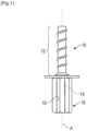
- the first section 12 of the screw 10 is visible at figure 1
- This section is of the self-tapping type in that it is intended to be screwed directly into a hole in the ceiling and to itself form a complementary thread in this hole when screwing in the screw.
- the second section 14 of the screw is not visible at the figure 1 . It comprises an external thread for screwing a coupling element 16 (also called a coupler).
- the coupling element 16 has a generally tubular shape and comprises an internal thread 18 which extends over the entire axial dimension of the element to allow on the one hand its screwing onto the second section 14 of the screw and on the other hand the screwing of a threaded rod (not shown) for suspending the frame.
- the coupling element 16 is screwed by one end of its thread 18 onto the second section 14 and receives the threaded rod by its opposite end.
- the screw 10 is of the type illustrated to the figure 2 of the document FR-A1-3 038 354 and the figure 1 of this same document teaches that the coupling element 16 can be formed in one piece with the screw.
- the coupling element 16 then forms a second axial drive section of the screw which is configured to be engaged with a tool in order to rotate and screw the screw into the hole.
- the screw is generally made of a metal alloy.
- Screwing screws of this type into holes in a ceiling allows a framework to be suspended for a false ceiling made of plasterboard.
- the plasterboards are screwed onto rails that are suspended from the concrete ceiling by threaded rods.
- the threaded rods each have a lower end screwed into a rail support called a rider, and an upper end screwed into the coupling element of a concrete screw.
- This type of ceiling is relatively heavy and the screws and threaded rods help to withstand this heavy load.
- a hanger generally consists of two parallel rods connected together by a spring blade. Each of the rods has a curved end that serves as a hook and the hooks of the two rods can be brought closer or further apart by means of the spring blade, depending on the distance to be provided between the ceiling and the false ceiling.
- One of the hooks of the hanger is fixed to a profile of the false ceiling and the other hook is engaged in a hole in a hammer-in anchor previously engaged in a hole in the ceiling using a hammer.
- the present invention relates to a concrete screw according to claim 1.
- the screw can be used for both types of false ceilings mentioned above, namely plasterboard false ceilings and slab false ceilings.
- the recess present on the screw allows the screw to cooperate with a hook of a hanger for installing a slab false ceiling
- the second section of the screw allows the screw to cooperate with a threaded rod for suspending a plasterboard false ceiling. Workers who have to install these two types of false ceiling in the same building can therefore use a single and same fixing system reference, namely the screw according to the invention.
- the present invention also relates to a kit for suspending a false ceiling frame, comprising at least one concrete screw as described above, with at least one hanger and/or at least one threaded rod.
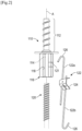
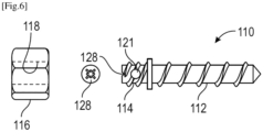
- FIG 2 represents a concrete screw 110 capable of cooperating on the one hand with a threaded rod 120 and on the other hand with a hanger 122, one or the other depending on the type of false ceiling envisaged.
- the first section 112 of the screw 110 is visible at figure 2 .
- This section 112 is of the self-tapping type insofar as it is intended to be screwed directly into an orifice in the concrete ceiling and to itself form a complementary thread in this orifice when screwing in the screw.
- the dimensional characteristics of this section can be determined by a person skilled in the art, in particular with regard to the teaching of the document FR-A1-2 521 235 .
- the second section 114 of the screw is not visible at the figure 2 . It comprises an external thread for screwing a coupling element 116 (also called a coupler).
- the coupling element 116 has a generally tubular shape and comprises an internal thread 118 which extends over the entire axial dimension of the element to allow on the one hand its screwing onto the second section 114 and on the other hand the screwing of the threaded rod 120.
- the coupling element 116 is screwed by one end of its thread 118 onto the second section 114 and receives the threaded rod 120 by its opposite end.
- the coupling element 116 has a hexagonal external profile in cross section so that it can be engaged and rotated by means of an appropriate tool.
- the screw 110 and for example its coupling element 116, comprises a transverse recess 121 configured to receive one end of a hanger 122.
- the hanger 122 comprises two parallel rods 122a, 122b connected to each other by a spring blade 124.
- Each of the rods 122a, 122b has a curved end which serves as a hook 126 and the hooks of the two rods can be brought closer together or moved away from each other at the same time. by means of the spring blade 124, depending on the distance to be provided between the ceiling and the false ceiling.
- One of the hooks of the hanger is fixed to a profile of the false ceiling and the other hook is engaged in the recess 121 of the screw 110.
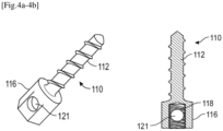
- the screw 110 is in two parts manufactured independently of each other.
- the first part of the screw comprises the first section 112 as well as an external thread forming the second section 114.
- the second part is formed by the coupling element 116 which is attached and screwed onto the external thread of the second section 114, as in the figure 2 .
- the coupling element is configured to be engaged with a tool for driving and screwing the screw.
- This coupling element 116 comprises a recess 121 in the form of a notch which extends in a plane passing through the axis A of the screw 110 over a major part of its length. This notch can extend over the entire transverse dimension of the element 116 or only part of this dimension.
- the notch is sized to receive a hanger hook 126 and has for example a thickness or width L1 greater than or equal to 5 mm or even 6 mm.
- the notch has a length L2 measured along the axis A which is sufficient to accommodate the hook 126 when the element 116 is screwed onto the thread 114.
- the recess 121 could be in the form of an orifice, as in the figure 2 , which could extend over all or part of the transverse dimension of element 116.
- the screw 110 is formed in one piece, that is to say that its coupling element 116 is integrated into the screw 110.
- the coupling element 116 forms the second section 114 of the screw and comprises a recess 121 in the form of a transverse orifice, which passes through a central tapped orifice.
- the element 116 therefore comprises the internal thread 118 for screwing the threaded rod.
- the screw 110 is formed in one piece, that is to say that its coupling element 116 is integrated into the screw.
- the coupling element 116 forms the second section 114 and comprises a recess 121 in the form of a transverse orifice, which is located at a distance from a central tapped orifice 118.
- the element 116 therefore comprises the internal thread 118 for screwing the threaded rod.
- the second section of the screw can thus comprise two adjacent parts, a first comprising the hexagonal external drive profile and the orifice 118, and a second extending between this first part and the first section 112, and comprising the recess 121.
- FIG. 6 illustrates another embodiment in which the recess 121 is formed on the external thread of the second section 114.
- the engagement and rotational driving of the screw is here carried out by means of an imprint 128 made at the free end of the second section 114.
- This imprint 128, for example of the TORX® type, is configured to receive a complementary tip of a drive tool carried by a screwdriver or the like.
- a coupling element 116 can further be screwed onto the second section 114 if the screw is to be used in combination with a threaded rod.
- FIG 7 illustrates a variant which is distinct from that of the figure 6 in that the screw 110 comprises, between the external thread 114 and the first section 112, a hexagonal external drive profile. This hexagonal profile replaces the imprint 128 of the figure 6 .
- FIG 8 illustrates a variant which is distinct from that of the figure 7 in that the recess 121 is no longer located on the external thread of the second section 114 but on the external hexagonal drive profile.
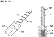
- FIG. 9 illustrates another variant close to the embodiments of the Figures 4a to 5b .
- the variant of the figure 9 differs from these embodiments primarily in that the recess 121 is in the form of a notch or slot and not an orifice.
- the notch is formed on one side of the member 116 and defines a hook for receiving and retaining one end of a hanger rod.
Landscapes
- Engineering & Computer Science (AREA)
- General Engineering & Computer Science (AREA)
- Mechanical Engineering (AREA)
- Joining Of Building Structures In Genera (AREA)
Claims (10)
- Betonschraube (110) zum Aufhängen eines Zwischendeckengitters, wobei die Betonschraube eine im Allgemeinen längliche Form entlang einer Achse (A) hat und einen ersten axialen Abschnitt (112) mit einem Außengewinde, das so konfiguriert ist, dass es direkt in ein Loch geschraubt wird, das in einer Betondecke gebildet ist, und einen zweiten axialen Abschnitt (114) zum Treiben der Schraube aufweist, der so konfiguriert ist, dass er mit einem Werkzeug im Eingriff ist, um die Schraube zu drehen und in das Loch einzuschrauben, wobei dieser zweite Abschnitt ein Außengewinde aufweist, das so konfiguriert ist, dass es ein Element (116) durch Schrauben mit einer Gewindestange (120) koppelt, um das Gitter aufzuhängen, wobei die Schraube (110) eine Querausnehmung (121) aufweist, die so konfiguriert ist, dass sie ein Ende eines Aufhängeelements (122) zum Aufhängen des Gitters aufnimmt, wobei die Betonschraube (110) dadurch gekennzeichnet ist, dass die Ausnehmung (121) durch das Außengewinde verläuft, wobei die Ausnehmung (121) in dem zweiten Abschnitt ausgebildet ist.
- Betonschraube (110) nach Anspruch 1, wobei sie eine einzige Ausnehmung (121) aufweist.
- Betonschraube (110) nach einem der Ansprüche 1 bis 2, wobei die Ausnehmung die Form einer Queröffnung oder Querkerbe hat.
- Betonschraube (110) nach einem der Ansprüche 1 bis 3, wobei der erste und der zweite Abschnitt aus ein und demselben Stück hergestellt sind.
- Betonschraube (110) nach einem der Ansprüche 1 bis 4, wobei der zweite Abschnitt in seinem axialen Abschnitt eine sechseckige äußere Umfangskante aufweist.
- Betonschraube (110) nach einem der Ansprüche 1 bis 5, wobei der zweite Abschnitt ein Gewindeloch aufweist, das zur Aufnahme der Gewindestange konfiguriert ist.
- Betonschraube (110) nach einem der Ansprüche 1 bis 6, die ferner ein Kopplungselement, daseine sechseckige äußere Umfangskante in seinem axialen Abschnitt aufweist, undeine zentrale Gewindebohrung aufweist, die einerseits auf das Außengewinde des zweiten Abschnitts aufzuschrauben ist und andererseits die Gewindestange aufnimmt.
- Betonschraube (110) nach einem der Ansprüche 1 bis 7, wobei die Ausnehmung (121) einen Durchmesser größer gleich 5 mm und vorzugsweise größer gleich 6 mm aufweist.
- Bausatz zum Aufhängen eines Zwischendeckengitters, der zumindest eine Betonschraube (110) nach einem der vorhergehenden Ansprüche mit zumindest einem Aufhängeelement (122) und/oder zumindest einer Gewindestange (120) aufweist.
- Verfahren zum Installieren eines Zwischendeckengitters unter Verwendung von Betonschrauben (110) nach einem der Ansprüche 1 bis 8, das die folgenden Schritte aufweist:- Einschrauben dieser Schrauben direkt in Bohrungen in Betondecken,- Eingreifen der Enden des Aufhängeelements (122) in die Ausnehmungen einiger dieser Schrauben, und- Einschrauben von Gewindestangen (120) in Gewindebohrungen in den anderen Schrauben oder in Gewindebohrungen in an diesen anderen Schrauben befestigten Kupplungselementen (116).
Priority Applications (2)
| Application Number | Priority Date | Filing Date | Title |
|---|---|---|---|
| EP19179807.3A EP3751158B1 (de) | 2019-06-12 | 2019-06-12 | Betonschraube für die aufhängung einer skelettbaukonstuktion für abgehängte decke |
| ES19179807T ES2990260T3 (es) | 2019-06-12 | 2019-06-12 | Tornillo para hormigón para colgar un armazón de un techo suspendido |
Applications Claiming Priority (1)
| Application Number | Priority Date | Filing Date | Title |
|---|---|---|---|
| EP19179807.3A EP3751158B1 (de) | 2019-06-12 | 2019-06-12 | Betonschraube für die aufhängung einer skelettbaukonstuktion für abgehängte decke |
Publications (2)
| Publication Number | Publication Date |
|---|---|
| EP3751158A1 EP3751158A1 (de) | 2020-12-16 |
| EP3751158B1 true EP3751158B1 (de) | 2024-08-14 |
Family
ID=66857683
Family Applications (1)
| Application Number | Title | Priority Date | Filing Date |
|---|---|---|---|
| EP19179807.3A Active EP3751158B1 (de) | 2019-06-12 | 2019-06-12 | Betonschraube für die aufhängung einer skelettbaukonstuktion für abgehängte decke |
Country Status (2)
| Country | Link |
|---|---|
| EP (1) | EP3751158B1 (de) |
| ES (1) | ES2990260T3 (de) |
Families Citing this family (1)
| Publication number | Priority date | Publication date | Assignee | Title |
|---|---|---|---|---|
| FR3129694B1 (fr) * | 2021-11-30 | 2023-12-08 | Francois Inglese | Piton de suspension perfectionné |
Citations (1)
| Publication number | Priority date | Publication date | Assignee | Title |
|---|---|---|---|---|
| EP2920476B1 (de) * | 2012-11-19 | 2017-11-01 | Infastech Intellectual Properties Pte. Ltd. | Kombination aus aufhänger und befestiger |
Family Cites Families (5)
| Publication number | Priority date | Publication date | Assignee | Title |
|---|---|---|---|---|
| US4439077A (en) | 1982-02-11 | 1984-03-27 | Godsted Kent B | Concrete screw anchor |
| DE8901693U1 (de) * | 1989-02-07 | 1989-07-27 | Blümling, Franz J., 6231 Sulzbach | Doppelschrauben-Verbindungsmuffe mit Absicherungsschutz |
| US7082664B2 (en) * | 2002-11-15 | 2006-08-01 | Powers Fasteners, Inc. | Method for mounting an anchor |
| CA2815508A1 (en) * | 2013-03-08 | 2014-09-08 | Mitek Holdings, Inc. | Sealing anchor and anchoring system for insulated panel walls |
| FR3038354B1 (fr) | 2015-07-03 | 2017-12-29 | Sarl Francois Inglese | Piton de suspension |
-
2019
- 2019-06-12 ES ES19179807T patent/ES2990260T3/es active Active
- 2019-06-12 EP EP19179807.3A patent/EP3751158B1/de active Active
Patent Citations (1)
| Publication number | Priority date | Publication date | Assignee | Title |
|---|---|---|---|---|
| EP2920476B1 (de) * | 2012-11-19 | 2017-11-01 | Infastech Intellectual Properties Pte. Ltd. | Kombination aus aufhänger und befestiger |
Also Published As
| Publication number | Publication date |
|---|---|
| ES2990260T3 (es) | 2024-11-29 |
| EP3751158A1 (de) | 2020-12-16 |
Similar Documents
| Publication | Publication Date | Title |
|---|---|---|
| BE1004847A6 (fr) | Assemblage et procede d'ancrage empechant l'arrachement. | |
| EP3213039A1 (de) | Vorrichtung und verfahren zur montage und ausrichtung eines sensors auf einem träger | |
| EP2664731A1 (de) | Verfahren und Vorrichtung zum Befestigen eines Verkleidungsschilds mit genuteter Kante auf einem Halteprofil, und Gesamtanordnung, die aus mindestens einer Befestigungsvorrichtung vom genannten Typ besteht | |
| EP3620665A1 (de) | Schraube mit sollbruchstelle, befestigung mit einer solchen schraube, entsprechender zusammenbau und entsprechendes installationsverfahren | |
| EP2795141B1 (de) | System zum befestigen eines objekts an einem element mit befestigungsrille(n) und befestigungsvorrichtung für ein solches system | |
| EP3751158B1 (de) | Betonschraube für die aufhängung einer skelettbaukonstuktion für abgehängte decke | |
| WO2019073076A1 (fr) | Ecrou rainuré pour fixation aveugle, rivet et assemblage comportant un tel écrou | |
| FR2959284A1 (fr) | Dispositif de fixation rapide par insertion avec possibilite d'ajustement | |
| FR2922237A1 (fr) | Attache pour panneaux de faux-plafonds. | |
| FR3038354A1 (fr) | Piton de suspension | |
| FR2920798A1 (fr) | Plafond suspendu | |
| FR2941504A1 (fr) | Ecrou a montage rapide | |
| FR2966211A1 (fr) | Equerre de fixation et mode de pose | |
| EP1870541B1 (de) | Vorrichtung zum Befestigen eines Schließstators | |
| FR2989396A1 (fr) | Suspente extensible | |
| WO2012136922A1 (fr) | Dispositif pour assujettir une vis d'assemblage a un element devant etre fixe sur un autre element | |
| FR2816014A1 (fr) | Vis pour ancrer un profil creux dans une infrastructure | |
| EP3839656A1 (de) | Unruh für uhrwerk | |
| BE1027500B1 (fr) | Embout et procédé de vissage de crochet de maçonnerie | |
| WO2025003353A1 (fr) | Ancrage pour plafond | |
| EP3380681B1 (de) | Verankerungselement für ein sanitärbefestigungselement | |
| FR2961678A1 (fr) | Ensemble d'elements permettant de constituer un dispositif de fixation de tringle a rideaux sur caisson de volet roulant et dispositif de fixation obtenu | |
| EP4339075A1 (de) | Kraftfahrzeugstrukturanordnung mit hohlkörpern | |
| WO2025003348A1 (fr) | Ancrage pour plafond | |
| FR3113229A1 (fr) | Ensemble de fixation murale présentant des crochets, et organe complémentaire correspondant |
Legal Events
| Date | Code | Title | Description |
|---|---|---|---|
| PUAI | Public reference made under article 153(3) epc to a published international application that has entered the european phase |
Free format text: ORIGINAL CODE: 0009012 |
|
| STAA | Information on the status of an ep patent application or granted ep patent |
Free format text: STATUS: THE APPLICATION HAS BEEN PUBLISHED |
|
| AK | Designated contracting states |
Kind code of ref document: A1 Designated state(s): AL AT BE BG CH CY CZ DE DK EE ES FI FR GB GR HR HU IE IS IT LI LT LU LV MC MK MT NL NO PL PT RO RS SE SI SK SM TR |
|
| AX | Request for extension of the european patent |
Extension state: BA ME |
|
| STAA | Information on the status of an ep patent application or granted ep patent |
Free format text: STATUS: REQUEST FOR EXAMINATION WAS MADE |
|
| 17P | Request for examination filed |
Effective date: 20210615 |
|
| RBV | Designated contracting states (corrected) |
Designated state(s): AL AT BE BG CH CY CZ DE DK EE ES FI FR GB GR HR HU IE IS IT LI LT LU LV MC MK MT NL NO PL PT RO RS SE SI SK SM TR |
|
| STAA | Information on the status of an ep patent application or granted ep patent |
Free format text: STATUS: EXAMINATION IS IN PROGRESS |
|
| 17Q | First examination report despatched |
Effective date: 20221207 |
|
| GRAP | Despatch of communication of intention to grant a patent |
Free format text: ORIGINAL CODE: EPIDOSNIGR1 |
|
| STAA | Information on the status of an ep patent application or granted ep patent |
Free format text: STATUS: GRANT OF PATENT IS INTENDED |
|
| INTG | Intention to grant announced |
Effective date: 20240220 |
|
| GRAJ | Information related to disapproval of communication of intention to grant by the applicant or resumption of examination proceedings by the epo deleted |
Free format text: ORIGINAL CODE: EPIDOSDIGR1 |
|
| STAA | Information on the status of an ep patent application or granted ep patent |
Free format text: STATUS: EXAMINATION IS IN PROGRESS |
|
| GRAP | Despatch of communication of intention to grant a patent |
Free format text: ORIGINAL CODE: EPIDOSNIGR1 |
|
| STAA | Information on the status of an ep patent application or granted ep patent |
Free format text: STATUS: GRANT OF PATENT IS INTENDED |
|
| INTG | Intention to grant announced |
Effective date: 20240408 |
|
| P01 | Opt-out of the competence of the unified patent court (upc) registered |
Effective date: 20240416 |
|
| GRAS | Grant fee paid |
Free format text: ORIGINAL CODE: EPIDOSNIGR3 |
|
| GRAA | (expected) grant |
Free format text: ORIGINAL CODE: 0009210 |
|
| STAA | Information on the status of an ep patent application or granted ep patent |
Free format text: STATUS: THE PATENT HAS BEEN GRANTED |
|
| AK | Designated contracting states |
Kind code of ref document: B1 Designated state(s): AL AT BE BG CH CY CZ DE DK EE ES FI FR GB GR HR HU IE IS IT LI LT LU LV MC MK MT NL NO PL PT RO RS SE SI SK SM TR |
|
| REG | Reference to a national code |
Ref country code: GB Ref legal event code: FG4D Free format text: NOT ENGLISH |
|
| REG | Reference to a national code |
Ref country code: CH Ref legal event code: EP |
|
| REG | Reference to a national code |
Ref country code: DE Ref legal event code: R096 Ref document number: 602019056893 Country of ref document: DE |
|
| REG | Reference to a national code |
Ref country code: IE Ref legal event code: FG4D Free format text: LANGUAGE OF EP DOCUMENT: FRENCH |
|
| REG | Reference to a national code |
Ref country code: ES Ref legal event code: FG2A Ref document number: 2990260 Country of ref document: ES Kind code of ref document: T3 Effective date: 20241129 |
|
| REG | Reference to a national code |
Ref country code: LT Ref legal event code: MG9D |
|
| REG | Reference to a national code |
Ref country code: NL Ref legal event code: MP Effective date: 20240814 |
|
| PG25 | Lapsed in a contracting state [announced via postgrant information from national office to epo] |
Ref country code: NO Free format text: LAPSE BECAUSE OF FAILURE TO SUBMIT A TRANSLATION OF THE DESCRIPTION OR TO PAY THE FEE WITHIN THE PRESCRIBED TIME-LIMIT Effective date: 20241114 |
|
| REG | Reference to a national code |
Ref country code: AT Ref legal event code: MK05 Ref document number: 1713542 Country of ref document: AT Kind code of ref document: T Effective date: 20240814 |
|
| PG25 | Lapsed in a contracting state [announced via postgrant information from national office to epo] |
Ref country code: NL Free format text: LAPSE BECAUSE OF FAILURE TO SUBMIT A TRANSLATION OF THE DESCRIPTION OR TO PAY THE FEE WITHIN THE PRESCRIBED TIME-LIMIT Effective date: 20240814 Ref country code: PT Free format text: LAPSE BECAUSE OF FAILURE TO SUBMIT A TRANSLATION OF THE DESCRIPTION OR TO PAY THE FEE WITHIN THE PRESCRIBED TIME-LIMIT Effective date: 20241216 Ref country code: GR Free format text: LAPSE BECAUSE OF FAILURE TO SUBMIT A TRANSLATION OF THE DESCRIPTION OR TO PAY THE FEE WITHIN THE PRESCRIBED TIME-LIMIT Effective date: 20241115 Ref country code: PL Free format text: LAPSE BECAUSE OF FAILURE TO SUBMIT A TRANSLATION OF THE DESCRIPTION OR TO PAY THE FEE WITHIN THE PRESCRIBED TIME-LIMIT Effective date: 20240814 Ref country code: FI Free format text: LAPSE BECAUSE OF FAILURE TO SUBMIT A TRANSLATION OF THE DESCRIPTION OR TO PAY THE FEE WITHIN THE PRESCRIBED TIME-LIMIT Effective date: 20240814 |
|
| PG25 | Lapsed in a contracting state [announced via postgrant information from national office to epo] |
Ref country code: BG Free format text: LAPSE BECAUSE OF FAILURE TO SUBMIT A TRANSLATION OF THE DESCRIPTION OR TO PAY THE FEE WITHIN THE PRESCRIBED TIME-LIMIT Effective date: 20240814 |
|
| PG25 | Lapsed in a contracting state [announced via postgrant information from national office to epo] |
Ref country code: LV Free format text: LAPSE BECAUSE OF FAILURE TO SUBMIT A TRANSLATION OF THE DESCRIPTION OR TO PAY THE FEE WITHIN THE PRESCRIBED TIME-LIMIT Effective date: 20240814 |
|
| PG25 | Lapsed in a contracting state [announced via postgrant information from national office to epo] |
Ref country code: IS Free format text: LAPSE BECAUSE OF FAILURE TO SUBMIT A TRANSLATION OF THE DESCRIPTION OR TO PAY THE FEE WITHIN THE PRESCRIBED TIME-LIMIT Effective date: 20241214 Ref country code: AT Free format text: LAPSE BECAUSE OF FAILURE TO SUBMIT A TRANSLATION OF THE DESCRIPTION OR TO PAY THE FEE WITHIN THE PRESCRIBED TIME-LIMIT Effective date: 20240814 |
|
| PG25 | Lapsed in a contracting state [announced via postgrant information from national office to epo] |
Ref country code: HR Free format text: LAPSE BECAUSE OF FAILURE TO SUBMIT A TRANSLATION OF THE DESCRIPTION OR TO PAY THE FEE WITHIN THE PRESCRIBED TIME-LIMIT Effective date: 20240814 |
|
| PG25 | Lapsed in a contracting state [announced via postgrant information from national office to epo] |
Ref country code: RS Free format text: LAPSE BECAUSE OF FAILURE TO SUBMIT A TRANSLATION OF THE DESCRIPTION OR TO PAY THE FEE WITHIN THE PRESCRIBED TIME-LIMIT Effective date: 20241114 |
|
| PG25 | Lapsed in a contracting state [announced via postgrant information from national office to epo] |
Ref country code: RS Free format text: LAPSE BECAUSE OF FAILURE TO SUBMIT A TRANSLATION OF THE DESCRIPTION OR TO PAY THE FEE WITHIN THE PRESCRIBED TIME-LIMIT Effective date: 20241114 Ref country code: PT Free format text: LAPSE BECAUSE OF FAILURE TO SUBMIT A TRANSLATION OF THE DESCRIPTION OR TO PAY THE FEE WITHIN THE PRESCRIBED TIME-LIMIT Effective date: 20241216 Ref country code: PL Free format text: LAPSE BECAUSE OF FAILURE TO SUBMIT A TRANSLATION OF THE DESCRIPTION OR TO PAY THE FEE WITHIN THE PRESCRIBED TIME-LIMIT Effective date: 20240814 Ref country code: NO Free format text: LAPSE BECAUSE OF FAILURE TO SUBMIT A TRANSLATION OF THE DESCRIPTION OR TO PAY THE FEE WITHIN THE PRESCRIBED TIME-LIMIT Effective date: 20241114 Ref country code: NL Free format text: LAPSE BECAUSE OF FAILURE TO SUBMIT A TRANSLATION OF THE DESCRIPTION OR TO PAY THE FEE WITHIN THE PRESCRIBED TIME-LIMIT Effective date: 20240814 Ref country code: LV Free format text: LAPSE BECAUSE OF FAILURE TO SUBMIT A TRANSLATION OF THE DESCRIPTION OR TO PAY THE FEE WITHIN THE PRESCRIBED TIME-LIMIT Effective date: 20240814 Ref country code: IS Free format text: LAPSE BECAUSE OF FAILURE TO SUBMIT A TRANSLATION OF THE DESCRIPTION OR TO PAY THE FEE WITHIN THE PRESCRIBED TIME-LIMIT Effective date: 20241214 Ref country code: HR Free format text: LAPSE BECAUSE OF FAILURE TO SUBMIT A TRANSLATION OF THE DESCRIPTION OR TO PAY THE FEE WITHIN THE PRESCRIBED TIME-LIMIT Effective date: 20240814 Ref country code: GR Free format text: LAPSE BECAUSE OF FAILURE TO SUBMIT A TRANSLATION OF THE DESCRIPTION OR TO PAY THE FEE WITHIN THE PRESCRIBED TIME-LIMIT Effective date: 20241115 Ref country code: FI Free format text: LAPSE BECAUSE OF FAILURE TO SUBMIT A TRANSLATION OF THE DESCRIPTION OR TO PAY THE FEE WITHIN THE PRESCRIBED TIME-LIMIT Effective date: 20240814 Ref country code: BG Free format text: LAPSE BECAUSE OF FAILURE TO SUBMIT A TRANSLATION OF THE DESCRIPTION OR TO PAY THE FEE WITHIN THE PRESCRIBED TIME-LIMIT Effective date: 20240814 Ref country code: AT Free format text: LAPSE BECAUSE OF FAILURE TO SUBMIT A TRANSLATION OF THE DESCRIPTION OR TO PAY THE FEE WITHIN THE PRESCRIBED TIME-LIMIT Effective date: 20240814 |
|
| PG25 | Lapsed in a contracting state [announced via postgrant information from national office to epo] |
Ref country code: SM Free format text: LAPSE BECAUSE OF FAILURE TO SUBMIT A TRANSLATION OF THE DESCRIPTION OR TO PAY THE FEE WITHIN THE PRESCRIBED TIME-LIMIT Effective date: 20240814 Ref country code: DK Free format text: LAPSE BECAUSE OF FAILURE TO SUBMIT A TRANSLATION OF THE DESCRIPTION OR TO PAY THE FEE WITHIN THE PRESCRIBED TIME-LIMIT Effective date: 20240814 Ref country code: RO Free format text: LAPSE BECAUSE OF FAILURE TO SUBMIT A TRANSLATION OF THE DESCRIPTION OR TO PAY THE FEE WITHIN THE PRESCRIBED TIME-LIMIT Effective date: 20240814 |
|
| PG25 | Lapsed in a contracting state [announced via postgrant information from national office to epo] |
Ref country code: EE Free format text: LAPSE BECAUSE OF FAILURE TO SUBMIT A TRANSLATION OF THE DESCRIPTION OR TO PAY THE FEE WITHIN THE PRESCRIBED TIME-LIMIT Effective date: 20240814 |
|
| PG25 | Lapsed in a contracting state [announced via postgrant information from national office to epo] |
Ref country code: CZ Free format text: LAPSE BECAUSE OF FAILURE TO SUBMIT A TRANSLATION OF THE DESCRIPTION OR TO PAY THE FEE WITHIN THE PRESCRIBED TIME-LIMIT Effective date: 20240814 |
|
| PG25 | Lapsed in a contracting state [announced via postgrant information from national office to epo] |
Ref country code: SK Free format text: LAPSE BECAUSE OF FAILURE TO SUBMIT A TRANSLATION OF THE DESCRIPTION OR TO PAY THE FEE WITHIN THE PRESCRIBED TIME-LIMIT Effective date: 20240814 Ref country code: IT Free format text: LAPSE BECAUSE OF FAILURE TO SUBMIT A TRANSLATION OF THE DESCRIPTION OR TO PAY THE FEE WITHIN THE PRESCRIBED TIME-LIMIT Effective date: 20240814 |
|
| REG | Reference to a national code |
Ref country code: DE Ref legal event code: R097 Ref document number: 602019056893 Country of ref document: DE |
|
| PLBE | No opposition filed within time limit |
Free format text: ORIGINAL CODE: 0009261 |
|
| STAA | Information on the status of an ep patent application or granted ep patent |
Free format text: STATUS: NO OPPOSITION FILED WITHIN TIME LIMIT |
|
| PGFP | Annual fee paid to national office [announced via postgrant information from national office to epo] |
Ref country code: DE Payment date: 20250627 Year of fee payment: 7 |
|
| PGFP | Annual fee paid to national office [announced via postgrant information from national office to epo] |
Ref country code: BE Payment date: 20250627 Year of fee payment: 7 |
|
| PGFP | Annual fee paid to national office [announced via postgrant information from national office to epo] |
Ref country code: FR Payment date: 20250625 Year of fee payment: 7 |
|
| 26N | No opposition filed |
Effective date: 20250515 |
|
| PG25 | Lapsed in a contracting state [announced via postgrant information from national office to epo] |
Ref country code: SE Free format text: LAPSE BECAUSE OF FAILURE TO SUBMIT A TRANSLATION OF THE DESCRIPTION OR TO PAY THE FEE WITHIN THE PRESCRIBED TIME-LIMIT Effective date: 20240814 |
|
| PGFP | Annual fee paid to national office [announced via postgrant information from national office to epo] |
Ref country code: ES Payment date: 20250701 Year of fee payment: 7 |
|
| REG | Reference to a national code |
Ref country code: CH Ref legal event code: H13 Free format text: ST27 STATUS EVENT CODE: U-0-0-H10-H13 (AS PROVIDED BY THE NATIONAL OFFICE) Effective date: 20260127 |
|
| PG25 | Lapsed in a contracting state [announced via postgrant information from national office to epo] |
Ref country code: MC Free format text: LAPSE BECAUSE OF FAILURE TO SUBMIT A TRANSLATION OF THE DESCRIPTION OR TO PAY THE FEE WITHIN THE PRESCRIBED TIME-LIMIT Effective date: 20240814 |
|
| PG25 | Lapsed in a contracting state [announced via postgrant information from national office to epo] |
Ref country code: LU Free format text: LAPSE BECAUSE OF NON-PAYMENT OF DUE FEES Effective date: 20250612 |
|
| GBPC | Gb: european patent ceased through non-payment of renewal fee |
Effective date: 20250612 |