EP3751110B1 - Verbrennungsmotor - Google Patents
Verbrennungsmotor Download PDFInfo
- Publication number
- EP3751110B1 EP3751110B1 EP19751880.6A EP19751880A EP3751110B1 EP 3751110 B1 EP3751110 B1 EP 3751110B1 EP 19751880 A EP19751880 A EP 19751880A EP 3751110 B1 EP3751110 B1 EP 3751110B1
- Authority
- EP
- European Patent Office
- Prior art keywords
- cylinder
- hub
- piston
- crankshaft
- piston rod
- Prior art date
- Legal status (The legal status is an assumption and is not a legal conclusion. Google has not performed a legal analysis and makes no representation as to the accuracy of the status listed.)
- Active
Links
Images


Classifications
-
- F—MECHANICAL ENGINEERING; LIGHTING; HEATING; WEAPONS; BLASTING
- F02—COMBUSTION ENGINES; HOT-GAS OR COMBUSTION-PRODUCT ENGINE PLANTS
- F02B—INTERNAL-COMBUSTION PISTON ENGINES; COMBUSTION ENGINES IN GENERAL
- F02B41/00—Engines characterised by special means for improving conversion of heat or pressure energy into mechanical power
- F02B41/02—Engines with prolonged expansion
- F02B41/04—Engines with prolonged expansion in main cylinders
-
- F—MECHANICAL ENGINEERING; LIGHTING; HEATING; WEAPONS; BLASTING
- F01—MACHINES OR ENGINES IN GENERAL; ENGINE PLANTS IN GENERAL; STEAM ENGINES
- F01B—MACHINES OR ENGINES, IN GENERAL OR OF POSITIVE-DISPLACEMENT TYPE, e.g. STEAM ENGINES
- F01B9/00—Reciprocating-piston machines or engines characterised by connections between pistons and main shafts, not specific to groups F01B1/00 - F01B7/00
- F01B9/02—Reciprocating-piston machines or engines characterised by connections between pistons and main shafts, not specific to groups F01B1/00 - F01B7/00 with crankshaft
-
- F—MECHANICAL ENGINEERING; LIGHTING; HEATING; WEAPONS; BLASTING
- F02—COMBUSTION ENGINES; HOT-GAS OR COMBUSTION-PRODUCT ENGINE PLANTS
- F02B—INTERNAL-COMBUSTION PISTON ENGINES; COMBUSTION ENGINES IN GENERAL
- F02B2275/00—Other engines, components or details, not provided for in other groups of this subclass
- F02B2275/36—Modified dwell of piston in TDC
-
- F—MECHANICAL ENGINEERING; LIGHTING; HEATING; WEAPONS; BLASTING
- F02—COMBUSTION ENGINES; HOT-GAS OR COMBUSTION-PRODUCT ENGINE PLANTS
- F02B—INTERNAL-COMBUSTION PISTON ENGINES; COMBUSTION ENGINES IN GENERAL
- F02B75/00—Other engines
- F02B75/32—Engines characterised by connections between pistons and main shafts and not specific to preceding main groups
-
- F—MECHANICAL ENGINEERING; LIGHTING; HEATING; WEAPONS; BLASTING
- F16—ENGINEERING ELEMENTS AND UNITS; GENERAL MEASURES FOR PRODUCING AND MAINTAINING EFFECTIVE FUNCTIONING OF MACHINES OR INSTALLATIONS; THERMAL INSULATION IN GENERAL
- F16C—SHAFTS; FLEXIBLE SHAFTS; ELEMENTS OR CRANKSHAFT MECHANISMS; ROTARY BODIES OTHER THAN GEARING ELEMENTS; BEARINGS
- F16C7/00—Connecting-rods or like links pivoted at both ends; Construction of connecting-rod heads
- F16C7/02—Constructions of connecting-rods with constant length
- F16C7/023—Constructions of connecting-rods with constant length for piston engines, pumps or the like
Definitions
- the present invention relates to a combustion engine that has greater output than current combustion engines.
- Combustion engines comprise one or more hollow cylinders in an engine block, and inside each one a piston travels in a reciprocating linear motion and, depending on the type of fuel and/or engine cycles, travels between a top dead centre (TDC) and a bottom dead centre (BDC), and wherein the piston is driven by the combustion of a mixture of air and fuel that is synchronised with the point when the piston approximately reaches the top dead centre.
- TDC top dead centre
- BDC bottom dead centre
- the upper end of the cylinder configures a closed combustion chamber wherein the expansive wave pushes the piston towards the outside of the cylinder; coupling a foot of a piston rod with said piston through a bolt, and coupling the head at the opposite end of the piston rod to the crankshaft, thereby obtaining an engine torque in the shaft of said crankshaft.
- the aim is to synchronise the combustion with the point at which the piston reaches the top dead centre in the cylinder, since at that moment the compression of the mixture is greatest, the size of the combustion chamber is smallest, and the greatest output is obtained from the expansive wave.
- this configuration has a drawback in that at the top dead centre, the piston rod is arranged perpendicular to the axis of the crankshaft, and the effective thrust results from the inertia of the motion the already had by the crankshaft and from the thrust of the piston rod driven by the piston, such that if the crankshaft were not in motion, it would bend or break the piston rod, since the thrust of the same would be exerted perpendicularly to the axis of the crankshaft.
- This configuration further implies that the torque applied to the crankshaft by the piston rod is less efficient due to the perpendicular nature of the piston rod to the axis of the crankshaft at the top dead centre, which is when the combustion is most explosive.
- piston skirts that are often the same height or higher than the diameter of the same. Said skirts increase the weight of the engine and engine inertia and increase the irregular wear of the cylinder due to a reciprocating motion that causes the lower edges thereof to rub against the inner walls of the cylinder with a certain torque or moment, due to the distance of said edges to the bolt that couples the piston to the piston rod.
- the combustion engine of the invention has a configuration that solves the aforementioned drawbacks, thereby obtaining a greater output.
- the engine of the invention is of the type that comprises at least one hollow cylinder, inside of which a piston travels in a linear reciprocating motion, coupled by means of a piston rod to a crankshaft, wherein the piston rod comprises:
- the tests performed have unexpectedly found a drastic reduction of CO and CO2 emissions, beyond what was expected by a lower consumption of fuel by increasing output, surely due to the fact that greater temperatures are reached in the combustion by taking place at the optimum moment (the TDC), with an apparent improved combustion, which could possibly reduce the requirements of current vehicles with regard to the filtering of exhaust gases (which often require the implementation of post combustion valves, filters, catalysts or additives), or at least improve the ecological efficiency of the engine.
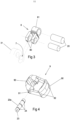
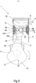
- the combustion engine (1) (see figures 5 to 9 ) of the invention is of the type that comprises at least one hollow cylinder (4) through which a piston (2) travels (also see fig. 2 ) in a linear reciprocating motion, coupled by means of a piston rod (3) (also see fig 1 ) to a crankshaft (10), wherein according to the invention, the piston rod (3) comprises (see fig. 1 ):
- the link rod (8) is in the shape of a fork, the side branches (80) of which are coupled to the third hub (7) of the piston rod (3), the central branch (81) of which is coupled with the piston (2) through the corresponding bolts (20), since in this manner the piston rod (8) can continue to have an essentially flat configuration and the piston (2) can have its traditional shape in order to enable the coupling thereof by means of the bolt (20), although with shorter skirts (22).
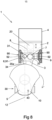
- the guide (9) ideally comprises a body with the general shape of a crown to enable the piston rod (3) to pass through the inside thereof and further surround the walls of the cylinder (4), having at least two curved faces (90) (see fig. 4 ) making contact with the walls of the cylinder (4) (which will then be facing one another, as seen in the figures), comprising a fourth hub (91) for coupling with the second hub (6) through an additional bolt (20a).
- This configuration with two curved faces (90) minimises the contact surfaces with the cylinder (4) as much as possible while maintaining the guide.
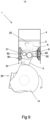
- the guide (9) preferably comprises oilers (92) to supply oil to said curved faces (90).
- These oilers (92) are ideally fed by means of a duct (34) that is made through the inside of the piston rod (3) through which pressurised oil runs and flows out at the second hub (6), to which said oilers (92) have access, the additional bolt (20a) in this case comprising an internal duct (23) with accesses (24) facing the duct (34) and oilers (92) to channel the oil to the same.
- the third hub (7) must be arranged (see fig. 1 ) in an area comprised in an angle from +60 degrees to -60 degrees with respect to a direction (11) that passes through the centre of the second hub (6) perpendicularly to the imaginary line (12) that joins the centre of the first hub (5) of the head (30) of the piston rod (3) and the centre of the second hub (6) of the foot (31) of the piston rod (3).
- said area is comprised between +45 degrees and -45 degrees.
- the head (30) of the piston rod (3) comprises a detachable section (33) in order to be able to detachably fasten it to the crankshaft (10).
Landscapes
- Engineering & Computer Science (AREA)
- Chemical & Material Sciences (AREA)
- Combustion & Propulsion (AREA)
- Mechanical Engineering (AREA)
- General Engineering & Computer Science (AREA)
- Shafts, Cranks, Connecting Bars, And Related Bearings (AREA)
- Pistons, Piston Rings, And Cylinders (AREA)
Claims (6)
- Verbrennungsmotor (1), der eine Kurbelwelle (10) und mindestens eine Zylinderbaugruppe umfasst, wobei jede Zylinderbaugruppe Folgendes umfasst:- einen Hohlzylinder (4),- einen Kolben (2), der sich in dem Zylinder (4) befindet und sich in dem Zylinder (4) in einer linearen Hin- und Herbewegung bewegen kann,- eine Führungseinheit (9), die sich in dem Zylinder (4) zwischen dem Kolben (2) und der Kurbelwelle (10) befindet und sich in dem Zylinder (4) in einer Hin- und Herbewegung bewegen kann,- eine Kolbenstange (3), die mit der Kurbelwelle (10) sowie mit der Führungseinheit (9) und über eine mit dem Kolben (2) gekoppelte Verbindungsstange (8) gekoppelt ist,
wobei die Kolbenstange (3) Folgendes aufweist- eine in ihrem Kopf (30) angeordnete erste Nabe (5) zur Kopplung mit der Kurbelwelle (10),- eine in ihrem Fuß (31) angeordnete zweite Nabe (6) zur Kopplung mit der Führungseinheit (9), und- eine in ihrem Fuß (31) angeordnete dritte Nabe (7) zur Kopplung mit der mit dem Kolben (2) gekoppelten Verbindungsstange (8),dadurch gekennzeichnet, dass die Zylinderbaugruppe so angeordnet ist, dass:- die zweite Nabe (6) der Kolbenstange (3) mit der Führungseinheit (9) an einer Stelle verbunden ist, die von der Mittellinie des Zylinders (4) um einen bestimmten Abstand versetzt ist,- sich die Kurbelwelle (10) versetzt von der Mittellinie des Zylinders (4) in einem Abstand befindet, der dem Abstand entspricht, um den die zweite Nabe (6) von der Mittellinie des Zylinders (4) versetzt ist, sodass, wenn die Kurbelwelle ihren OT erreicht, die erste Nabe (5) und die zweite Nabe (6) eine gedachte Linie parallel zur Mittellinie des Zylinders (4) bilden- die Verbindungsstange (8) mit dem Kolben (2) und der dritten Nabe (7) im Wesentlichen in der Mittellinie des Zylinders (4) verbunden ist, sodass die Verbindungsstange (8) im Wesentlichen mit der Mittellinie des Zylinders (4) ausgerichtet ist, wodurch eine Geometrie geschaffen wird, die Seitenkräfte auf den Kolben (2) vermeidet. - Verbrennungsmotor (1) nach Anspruch 1, wobei die Verbindungsstange (8) die Form einer Gabel hat, deren seitliche Zweige (80) mit der dritten Nabe (7) der Kolbenstange (3) gekoppelt sind und deren mittlerer Zweig (81) über die entsprechenden Bolzen (20) mit dem Kolben (2) gekoppelt ist.
- Verbrennungsmotor (1) nach einem der vorhergehenden Ansprüche, wobei die Führung (9) einen Körper mit der allgemeinen Form einer Krone umfasst, um den Durchgang der Kolbenstange (3) zu ermöglichen, mit mindestens zwei gekrümmten Flächen (90), die mit den Wänden des Zylinders (4) in Kontakt stehen, umfassend eine vierte Nabe (91) zur Kopplung mit der zweiten Nabe (6) über einen zusätzlichen Bolzen (20a).
- Verbrennungsmotor (1) nach einem der vorhergehenden Ansprüche, wobei die Führung (9) Öler (92) umfasst, um die gekrümmten Flächen (90) mit Öl zu versorgen.
- Verbrennungsmotor (1) nach Anspruch 4, wobei die Öler (92) mittels eines Kanals (34) gespeist werden, der durch das Innere der Kolbenstange (3) hindurch ausgeführt ist, durch den unter Druck stehendes Öl läuft und an der zweiten Nabe (6) ausströmt, zu der die Öler (92) Zugang haben; wobei der zusätzliche Bolzen (20a) einen inneren Kanal (23) mit Zugängen (24) umfasst, die dem Kanal (34) und den Ölern (92) gegenüberliegen, um das Öl zu diesen zu leiten.
- Verbrennungsmotor (1) nach einem der vorhergehenden Ansprüche, wobei der Kopf (30) der Kolbenstange (3) einen abnehmbaren Abschnitt (33) umfasst, um ihn abnehmbar an der Kurbelwelle (10) befestigen zu können.
Applications Claiming Priority (2)
| Application Number | Priority Date | Filing Date | Title |
|---|---|---|---|
| ES201830114A ES2722476B2 (es) | 2018-02-09 | 2018-02-09 | Motor de explosion |
| PCT/ES2019/070068 WO2019155108A1 (es) | 2018-02-09 | 2019-02-08 | Motor de explosión |
Publications (4)
| Publication Number | Publication Date |
|---|---|
| EP3751110A1 EP3751110A1 (de) | 2020-12-16 |
| EP3751110A4 EP3751110A4 (de) | 2021-12-01 |
| EP3751110C0 EP3751110C0 (de) | 2025-02-12 |
| EP3751110B1 true EP3751110B1 (de) | 2025-02-12 |
Family
ID=67513761
Family Applications (1)
| Application Number | Title | Priority Date | Filing Date |
|---|---|---|---|
| EP19751880.6A Active EP3751110B1 (de) | 2018-02-09 | 2019-02-08 | Verbrennungsmotor |
Country Status (5)
| Country | Link |
|---|---|
| US (1) | US20200400066A1 (de) |
| EP (1) | EP3751110B1 (de) |
| CN (1) | CN111699308A (de) |
| ES (1) | ES2722476B2 (de) |
| WO (1) | WO2019155108A1 (de) |
Families Citing this family (1)
| Publication number | Priority date | Publication date | Assignee | Title |
|---|---|---|---|---|
| US11885378B2 (en) * | 2021-06-04 | 2024-01-30 | Alfadan, Inc. | Cylinder unit for eliminating secondary forces in inline internal combustion engines |
Family Cites Families (13)
| Publication number | Priority date | Publication date | Assignee | Title |
|---|---|---|---|---|
| US1379115A (en) * | 1919-06-19 | 1921-05-24 | Mallory Marion | Internal-combustion engine |
| US2074581A (en) * | 1934-01-06 | 1937-03-23 | Robert G Frye | Piston for engines |
| FR833509A (fr) * | 1938-02-11 | 1938-10-24 | Piston | |
| US2368412A (en) * | 1943-10-11 | 1945-01-30 | William H Cords | Internal-combustion engine |
| US3034362A (en) * | 1960-07-21 | 1962-05-15 | Alfred M Caddell | Crank actuated means for retaining fluid pressure at top center |
| DE3129630A1 (de) * | 1981-07-28 | 1983-02-17 | Wenzel 3500 Kassel Schubert | Kolbentriebwerk fuer hubkolbenverbrennungskraftmaschine |
| DE3222568A1 (de) * | 1982-06-16 | 1983-12-22 | Josef 6761 Katzenbach Wilhelm | Kolben im kolben |
| US4567866A (en) * | 1984-12-26 | 1986-02-04 | Hans Schubert | Piston crankshaft interface |
| US4974554A (en) * | 1989-08-17 | 1990-12-04 | Emery Lloyd H | Compound rod, sleeve and offset crankshaft assembly |
| US5651304A (en) * | 1993-05-04 | 1997-07-29 | Neville Thomas Allsopp | Piston and connecting rod assembly |
| US5816201A (en) * | 1997-07-07 | 1998-10-06 | Garvin; Edward A. | Offset crankshaft mechanism for an internal combustion engine |
| US8720410B2 (en) * | 2012-10-08 | 2014-05-13 | Hans G. Schubert | Modified crankshaft piston interface for optimized cylinder pressure and torque output |
| DE102015203387A1 (de) * | 2015-02-25 | 2016-08-25 | Fev Gmbh | Doppelt wirkender Kolben eines VCR-Motors |
-
2018
- 2018-02-09 ES ES201830114A patent/ES2722476B2/es active Active
-
2019
- 2019-02-08 US US16/968,410 patent/US20200400066A1/en not_active Abandoned
- 2019-02-08 CN CN201980012532.8A patent/CN111699308A/zh active Pending
- 2019-02-08 EP EP19751880.6A patent/EP3751110B1/de active Active
- 2019-02-08 WO PCT/ES2019/070068 patent/WO2019155108A1/es not_active Ceased
Also Published As
| Publication number | Publication date |
|---|---|
| ES2722476A1 (es) | 2019-08-12 |
| EP3751110C0 (de) | 2025-02-12 |
| WO2019155108A1 (es) | 2019-08-15 |
| CN111699308A (zh) | 2020-09-22 |
| EP3751110A4 (de) | 2021-12-01 |
| ES2722476B2 (es) | 2021-10-07 |
| EP3751110A1 (de) | 2020-12-16 |
| ES2722476A8 (es) | 2020-08-07 |
| US20200400066A1 (en) | 2020-12-24 |
Similar Documents
| Publication | Publication Date | Title |
|---|---|---|
| JP2004536252A (ja) | 分割式4ストロークサイクル内燃機関 | |
| US8967097B2 (en) | Variable stroke mechanism for internal combustion engine | |
| US5544627A (en) | Engine design for gasoline/diesel engines | |
| US11519305B2 (en) | Internal combustion engine system | |
| KR101650818B1 (ko) | 내연 엔진을 위한 가변 행정 메커니즘 | |
| US10267225B2 (en) | Internal combustion engine | |
| EP3751110B1 (de) | Verbrennungsmotor | |
| KR20150132288A (ko) | 개선된 대향 피스톤 엔진 | |
| US10287971B2 (en) | Opposed piston engine | |
| CN103742263B (zh) | 连杆活塞式组合燃烧室无死点往复型内燃机 | |
| CN103850790B (zh) | 无死点往复式内燃机 | |
| US8667948B2 (en) | Dwell cycle crank | |
| NL2018451B1 (en) | Engine with two annular cylinders and two crankshafts | |
| CN203702338U (zh) | 连杆活塞式组合燃烧室无死点往复型内燃机 | |
| CN203730130U (zh) | 无死点往复式内燃机 | |
| AU2008201574B2 (en) | "Martin" cross-flow, 4 stroke side-valve engine | |
| CN1558097A (zh) | 双缸同时作功单曲轴对顶活塞内燃机 | |
| US8904990B2 (en) | Dwell cycle crank with rollers | |
| RU2536640C1 (ru) | Двигатель внутреннего сгорания | |
| CN108049972A (zh) | 一种无连杆式对置活塞二冲程内燃机 | |
| CN105257407A (zh) | 摆轴发动机 | |
| SK752013A3 (sk) | Spôsob riadenia pohybu vratného piesta piestového stroja a zariadenie | |
| JPS63295821A (ja) | 内燃機関 |
Legal Events
| Date | Code | Title | Description |
|---|---|---|---|
| STAA | Information on the status of an ep patent application or granted ep patent |
Free format text: STATUS: THE INTERNATIONAL PUBLICATION HAS BEEN MADE |
|
| PUAI | Public reference made under article 153(3) epc to a published international application that has entered the european phase |
Free format text: ORIGINAL CODE: 0009012 |
|
| STAA | Information on the status of an ep patent application or granted ep patent |
Free format text: STATUS: REQUEST FOR EXAMINATION WAS MADE |
|
| 17P | Request for examination filed |
Effective date: 20200810 |
|
| AK | Designated contracting states |
Kind code of ref document: A1 Designated state(s): AL AT BE BG CH CY CZ DE DK EE ES FI FR GB GR HR HU IE IS IT LI LT LU LV MC MK MT NL NO PL PT RO RS SE SI SK SM TR |
|
| AX | Request for extension of the european patent |
Extension state: BA ME |
|
| DAV | Request for validation of the european patent (deleted) | ||
| DAX | Request for extension of the european patent (deleted) | ||
| A4 | Supplementary search report drawn up and despatched |
Effective date: 20211028 |
|
| RIC1 | Information provided on ipc code assigned before grant |
Ipc: F02B 41/04 20060101ALI20211022BHEP Ipc: F02B 75/32 20060101AFI20211022BHEP |
|
| STAA | Information on the status of an ep patent application or granted ep patent |
Free format text: STATUS: EXAMINATION IS IN PROGRESS |
|
| 17Q | First examination report despatched |
Effective date: 20231110 |
|
| GRAP | Despatch of communication of intention to grant a patent |
Free format text: ORIGINAL CODE: EPIDOSNIGR1 |
|
| STAA | Information on the status of an ep patent application or granted ep patent |
Free format text: STATUS: GRANT OF PATENT IS INTENDED |
|
| INTG | Intention to grant announced |
Effective date: 20241030 |
|
| GRAS | Grant fee paid |
Free format text: ORIGINAL CODE: EPIDOSNIGR3 |
|
| GRAA | (expected) grant |
Free format text: ORIGINAL CODE: 0009210 |
|
| STAA | Information on the status of an ep patent application or granted ep patent |
Free format text: STATUS: THE PATENT HAS BEEN GRANTED |
|
| AK | Designated contracting states |
Kind code of ref document: B1 Designated state(s): AL AT BE BG CH CY CZ DE DK EE ES FI FR GB GR HR HU IE IS IT LI LT LU LV MC MK MT NL NO PL PT RO RS SE SI SK SM TR |
|
| REG | Reference to a national code |
Ref country code: GB Ref legal event code: FG4D |
|
| REG | Reference to a national code |
Ref country code: CH Ref legal event code: EP |
|
| REG | Reference to a national code |
Ref country code: DE Ref legal event code: R096 Ref document number: 602019065785 Country of ref document: DE |
|
| REG | Reference to a national code |
Ref country code: IE Ref legal event code: FG4D |
|
| U01 | Request for unitary effect filed |
Effective date: 20250303 |
|
| U07 | Unitary effect registered |
Designated state(s): AT BE BG DE DK EE FI FR IT LT LU LV MT NL PT RO SE SI Effective date: 20250311 |
|
| PG25 | Lapsed in a contracting state [announced via postgrant information from national office to epo] |
Ref country code: RS Free format text: LAPSE BECAUSE OF FAILURE TO SUBMIT A TRANSLATION OF THE DESCRIPTION OR TO PAY THE FEE WITHIN THE PRESCRIBED TIME-LIMIT Effective date: 20250512 |
|
| PG25 | Lapsed in a contracting state [announced via postgrant information from national office to epo] |
Ref country code: PL Free format text: LAPSE BECAUSE OF FAILURE TO SUBMIT A TRANSLATION OF THE DESCRIPTION OR TO PAY THE FEE WITHIN THE PRESCRIBED TIME-LIMIT Effective date: 20250212 |
|
| PG25 | Lapsed in a contracting state [announced via postgrant information from national office to epo] |
Ref country code: ES Free format text: LAPSE BECAUSE OF FAILURE TO SUBMIT A TRANSLATION OF THE DESCRIPTION OR TO PAY THE FEE WITHIN THE PRESCRIBED TIME-LIMIT Effective date: 20250212 |
|
| PG25 | Lapsed in a contracting state [announced via postgrant information from national office to epo] |
Ref country code: IS Free format text: LAPSE BECAUSE OF FAILURE TO SUBMIT A TRANSLATION OF THE DESCRIPTION OR TO PAY THE FEE WITHIN THE PRESCRIBED TIME-LIMIT Effective date: 20250612 Ref country code: NO Free format text: LAPSE BECAUSE OF FAILURE TO SUBMIT A TRANSLATION OF THE DESCRIPTION OR TO PAY THE FEE WITHIN THE PRESCRIBED TIME-LIMIT Effective date: 20250512 |
|
| PG25 | Lapsed in a contracting state [announced via postgrant information from national office to epo] |
Ref country code: HR Free format text: LAPSE BECAUSE OF FAILURE TO SUBMIT A TRANSLATION OF THE DESCRIPTION OR TO PAY THE FEE WITHIN THE PRESCRIBED TIME-LIMIT Effective date: 20250212 |
|
| PG25 | Lapsed in a contracting state [announced via postgrant information from national office to epo] |
Ref country code: SM Free format text: LAPSE BECAUSE OF FAILURE TO SUBMIT A TRANSLATION OF THE DESCRIPTION OR TO PAY THE FEE WITHIN THE PRESCRIBED TIME-LIMIT Effective date: 20250212 |
|
| PG25 | Lapsed in a contracting state [announced via postgrant information from national office to epo] |
Ref country code: CZ Free format text: LAPSE BECAUSE OF FAILURE TO SUBMIT A TRANSLATION OF THE DESCRIPTION OR TO PAY THE FEE WITHIN THE PRESCRIBED TIME-LIMIT Effective date: 20250212 |
|
| PG25 | Lapsed in a contracting state [announced via postgrant information from national office to epo] |
Ref country code: SK Free format text: LAPSE BECAUSE OF FAILURE TO SUBMIT A TRANSLATION OF THE DESCRIPTION OR TO PAY THE FEE WITHIN THE PRESCRIBED TIME-LIMIT Effective date: 20250212 |