EP3751107B1 - Verbrennungsmotor mit abgaswärmerückgewinnungssystem sowie verfahren zur abgaswärmerückgewinnung - Google Patents
Verbrennungsmotor mit abgaswärmerückgewinnungssystem sowie verfahren zur abgaswärmerückgewinnung Download PDFInfo
- Publication number
- EP3751107B1 EP3751107B1 EP20179402.1A EP20179402A EP3751107B1 EP 3751107 B1 EP3751107 B1 EP 3751107B1 EP 20179402 A EP20179402 A EP 20179402A EP 3751107 B1 EP3751107 B1 EP 3751107B1
- Authority
- EP
- European Patent Office
- Prior art keywords
- combustion engine
- internal combustion
- exhaust gas
- heat recovery
- recovery system
- Prior art date
- Legal status (The legal status is an assumption and is not a legal conclusion. Google has not performed a legal analysis and makes no representation as to the accuracy of the status listed.)
- Active
Links
- 238000002485 combustion reaction Methods 0.000 title claims description 90
- 238000011084 recovery Methods 0.000 title claims description 86
- 238000000034 method Methods 0.000 title claims description 39
- 238000004378 air conditioning Methods 0.000 claims description 62
- 239000007789 gas Substances 0.000 claims description 58
- 239000012530 fluid Substances 0.000 claims description 54
- 239000002826 coolant Substances 0.000 claims description 46
- 239000002918 waste heat Substances 0.000 claims description 43
- 239000003507 refrigerant Substances 0.000 claims description 42
- CURLTUGMZLYLDI-UHFFFAOYSA-N Carbon dioxide Chemical compound O=C=O CURLTUGMZLYLDI-UHFFFAOYSA-N 0.000 claims description 14
- 239000000498 cooling water Substances 0.000 claims description 11
- 238000011144 upstream manufacturing Methods 0.000 claims description 10
- LFQSCWFLJHTTHZ-UHFFFAOYSA-N Ethanol Chemical compound CCO LFQSCWFLJHTTHZ-UHFFFAOYSA-N 0.000 claims description 9
- 229910002092 carbon dioxide Inorganic materials 0.000 claims description 7
- 239000001569 carbon dioxide Substances 0.000 claims description 7
- 238000001816 cooling Methods 0.000 description 13
- 230000006835 compression Effects 0.000 description 7
- 238000007906 compression Methods 0.000 description 7
- 239000007788 liquid Substances 0.000 description 6
- 239000003054 catalyst Substances 0.000 description 5
- 238000010586 diagram Methods 0.000 description 3
- 239000000203 mixture Substances 0.000 description 3
- MWUXSHHQAYIFBG-UHFFFAOYSA-N nitrogen oxide Inorganic materials O=[N] MWUXSHHQAYIFBG-UHFFFAOYSA-N 0.000 description 3
- 238000009833 condensation Methods 0.000 description 2
- 230000005494 condensation Effects 0.000 description 2
- 238000013016 damping Methods 0.000 description 2
- 230000001419 dependent effect Effects 0.000 description 2
- 238000011161 development Methods 0.000 description 2
- 230000018109 developmental process Effects 0.000 description 2
- IDGUHHHQCWSQLU-UHFFFAOYSA-N ethanol;hydrate Chemical compound O.CCO IDGUHHHQCWSQLU-UHFFFAOYSA-N 0.000 description 2
- 238000001704 evaporation Methods 0.000 description 2
- 239000000446 fuel Substances 0.000 description 2
- 238000010438 heat treatment Methods 0.000 description 2
- XLYOFNOQVPJJNP-UHFFFAOYSA-N water Substances O XLYOFNOQVPJJNP-UHFFFAOYSA-N 0.000 description 2
- 230000015572 biosynthetic process Effects 0.000 description 1
- 238000009835 boiling Methods 0.000 description 1
- 230000001914 calming effect Effects 0.000 description 1
- 239000003990 capacitor Substances 0.000 description 1
- 238000010531 catalytic reduction reaction Methods 0.000 description 1
- 238000006243 chemical reaction Methods 0.000 description 1
- 230000008020 evaporation Effects 0.000 description 1
- 231100000252 nontoxic Toxicity 0.000 description 1
- 230000003000 nontoxic effect Effects 0.000 description 1
- 230000003647 oxidation Effects 0.000 description 1
- 238000007254 oxidation reaction Methods 0.000 description 1
- 239000002245 particle Substances 0.000 description 1
- 238000005086 pumping Methods 0.000 description 1
- 230000007704 transition Effects 0.000 description 1
Images

Classifications
-
- F—MECHANICAL ENGINEERING; LIGHTING; HEATING; WEAPONS; BLASTING
- F01—MACHINES OR ENGINES IN GENERAL; ENGINE PLANTS IN GENERAL; STEAM ENGINES
- F01N—GAS-FLOW SILENCERS OR EXHAUST APPARATUS FOR MACHINES OR ENGINES IN GENERAL; GAS-FLOW SILENCERS OR EXHAUST APPARATUS FOR INTERNAL COMBUSTION ENGINES
- F01N3/00—Exhaust or silencing apparatus having means for purifying, rendering innocuous, or otherwise treating exhaust
- F01N3/02—Exhaust or silencing apparatus having means for purifying, rendering innocuous, or otherwise treating exhaust for cooling, or for removing solid constituents of, exhaust
- F01N3/04—Exhaust or silencing apparatus having means for purifying, rendering innocuous, or otherwise treating exhaust for cooling, or for removing solid constituents of, exhaust using liquids
-
- F—MECHANICAL ENGINEERING; LIGHTING; HEATING; WEAPONS; BLASTING
- F01—MACHINES OR ENGINES IN GENERAL; ENGINE PLANTS IN GENERAL; STEAM ENGINES
- F01K—STEAM ENGINE PLANTS; STEAM ACCUMULATORS; ENGINE PLANTS NOT OTHERWISE PROVIDED FOR; ENGINES USING SPECIAL WORKING FLUIDS OR CYCLES
- F01K23/00—Plants characterised by more than one engine delivering power external to the plant, the engines being driven by different fluids
- F01K23/02—Plants characterised by more than one engine delivering power external to the plant, the engines being driven by different fluids the engine cycles being thermally coupled
- F01K23/06—Plants characterised by more than one engine delivering power external to the plant, the engines being driven by different fluids the engine cycles being thermally coupled combustion heat from one cycle heating the fluid in another cycle
- F01K23/10—Plants characterised by more than one engine delivering power external to the plant, the engines being driven by different fluids the engine cycles being thermally coupled combustion heat from one cycle heating the fluid in another cycle with exhaust fluid of one cycle heating the fluid in another cycle
-
- F—MECHANICAL ENGINEERING; LIGHTING; HEATING; WEAPONS; BLASTING
- F01—MACHINES OR ENGINES IN GENERAL; ENGINE PLANTS IN GENERAL; STEAM ENGINES
- F01K—STEAM ENGINE PLANTS; STEAM ACCUMULATORS; ENGINE PLANTS NOT OTHERWISE PROVIDED FOR; ENGINES USING SPECIAL WORKING FLUIDS OR CYCLES
- F01K23/00—Plants characterised by more than one engine delivering power external to the plant, the engines being driven by different fluids
- F01K23/02—Plants characterised by more than one engine delivering power external to the plant, the engines being driven by different fluids the engine cycles being thermally coupled
- F01K23/06—Plants characterised by more than one engine delivering power external to the plant, the engines being driven by different fluids the engine cycles being thermally coupled combustion heat from one cycle heating the fluid in another cycle
- F01K23/065—Plants characterised by more than one engine delivering power external to the plant, the engines being driven by different fluids the engine cycles being thermally coupled combustion heat from one cycle heating the fluid in another cycle the combustion taking place in an internal combustion piston engine, e.g. a diesel engine
-
- F—MECHANICAL ENGINEERING; LIGHTING; HEATING; WEAPONS; BLASTING
- F01—MACHINES OR ENGINES IN GENERAL; ENGINE PLANTS IN GENERAL; STEAM ENGINES
- F01N—GAS-FLOW SILENCERS OR EXHAUST APPARATUS FOR MACHINES OR ENGINES IN GENERAL; GAS-FLOW SILENCERS OR EXHAUST APPARATUS FOR INTERNAL COMBUSTION ENGINES
- F01N3/00—Exhaust or silencing apparatus having means for purifying, rendering innocuous, or otherwise treating exhaust
- F01N3/02—Exhaust or silencing apparatus having means for purifying, rendering innocuous, or otherwise treating exhaust for cooling, or for removing solid constituents of, exhaust
- F01N3/0205—Exhaust or silencing apparatus having means for purifying, rendering innocuous, or otherwise treating exhaust for cooling, or for removing solid constituents of, exhaust using heat exchangers
-
- F—MECHANICAL ENGINEERING; LIGHTING; HEATING; WEAPONS; BLASTING
- F01—MACHINES OR ENGINES IN GENERAL; ENGINE PLANTS IN GENERAL; STEAM ENGINES
- F01N—GAS-FLOW SILENCERS OR EXHAUST APPARATUS FOR MACHINES OR ENGINES IN GENERAL; GAS-FLOW SILENCERS OR EXHAUST APPARATUS FOR INTERNAL COMBUSTION ENGINES
- F01N5/00—Exhaust or silencing apparatus combined or associated with devices profiting from exhaust energy
- F01N5/02—Exhaust or silencing apparatus combined or associated with devices profiting from exhaust energy the devices using heat
-
- F—MECHANICAL ENGINEERING; LIGHTING; HEATING; WEAPONS; BLASTING
- F02—COMBUSTION ENGINES; HOT-GAS OR COMBUSTION-PRODUCT ENGINE PLANTS
- F02G—HOT GAS OR COMBUSTION-PRODUCT POSITIVE-DISPLACEMENT ENGINE PLANTS; USE OF WASTE HEAT OF COMBUSTION ENGINES; NOT OTHERWISE PROVIDED FOR
- F02G1/00—Hot gas positive-displacement engine plants
- F02G1/04—Hot gas positive-displacement engine plants of closed-cycle type
- F02G1/043—Hot gas positive-displacement engine plants of closed-cycle type the engine being operated by expansion and contraction of a mass of working gas which is heated and cooled in one of a plurality of constantly communicating expansible chambers, e.g. Stirling cycle type engines
- F02G1/045—Controlling
- F02G1/047—Controlling by varying the heating or cooling
-
- F—MECHANICAL ENGINEERING; LIGHTING; HEATING; WEAPONS; BLASTING
- F02—COMBUSTION ENGINES; HOT-GAS OR COMBUSTION-PRODUCT ENGINE PLANTS
- F02G—HOT GAS OR COMBUSTION-PRODUCT POSITIVE-DISPLACEMENT ENGINE PLANTS; USE OF WASTE HEAT OF COMBUSTION ENGINES; NOT OTHERWISE PROVIDED FOR
- F02G1/00—Hot gas positive-displacement engine plants
- F02G1/04—Hot gas positive-displacement engine plants of closed-cycle type
- F02G1/043—Hot gas positive-displacement engine plants of closed-cycle type the engine being operated by expansion and contraction of a mass of working gas which is heated and cooled in one of a plurality of constantly communicating expansible chambers, e.g. Stirling cycle type engines
- F02G1/053—Component parts or details
- F02G1/055—Heaters or coolers
-
- F—MECHANICAL ENGINEERING; LIGHTING; HEATING; WEAPONS; BLASTING
- F02—COMBUSTION ENGINES; HOT-GAS OR COMBUSTION-PRODUCT ENGINE PLANTS
- F02G—HOT GAS OR COMBUSTION-PRODUCT POSITIVE-DISPLACEMENT ENGINE PLANTS; USE OF WASTE HEAT OF COMBUSTION ENGINES; NOT OTHERWISE PROVIDED FOR
- F02G5/00—Profiting from waste heat of combustion engines, not otherwise provided for
- F02G5/02—Profiting from waste heat of exhaust gases
- F02G5/04—Profiting from waste heat of exhaust gases in combination with other waste heat from combustion engines
-
- F—MECHANICAL ENGINEERING; LIGHTING; HEATING; WEAPONS; BLASTING
- F01—MACHINES OR ENGINES IN GENERAL; ENGINE PLANTS IN GENERAL; STEAM ENGINES
- F01N—GAS-FLOW SILENCERS OR EXHAUST APPARATUS FOR MACHINES OR ENGINES IN GENERAL; GAS-FLOW SILENCERS OR EXHAUST APPARATUS FOR INTERNAL COMBUSTION ENGINES
- F01N2240/00—Combination or association of two or more different exhaust treating devices, or of at least one such device with an auxiliary device, not covered by indexing codes F01N2230/00 or F01N2250/00, one of the devices being
- F01N2240/02—Combination or association of two or more different exhaust treating devices, or of at least one such device with an auxiliary device, not covered by indexing codes F01N2230/00 or F01N2250/00, one of the devices being a heat exchanger
-
- F—MECHANICAL ENGINEERING; LIGHTING; HEATING; WEAPONS; BLASTING
- F01—MACHINES OR ENGINES IN GENERAL; ENGINE PLANTS IN GENERAL; STEAM ENGINES
- F01N—GAS-FLOW SILENCERS OR EXHAUST APPARATUS FOR MACHINES OR ENGINES IN GENERAL; GAS-FLOW SILENCERS OR EXHAUST APPARATUS FOR INTERNAL COMBUSTION ENGINES
- F01N2260/00—Exhaust treating devices having provisions not otherwise provided for
- F01N2260/02—Exhaust treating devices having provisions not otherwise provided for for cooling the device
- F01N2260/024—Exhaust treating devices having provisions not otherwise provided for for cooling the device using a liquid
-
- Y—GENERAL TAGGING OF NEW TECHNOLOGICAL DEVELOPMENTS; GENERAL TAGGING OF CROSS-SECTIONAL TECHNOLOGIES SPANNING OVER SEVERAL SECTIONS OF THE IPC; TECHNICAL SUBJECTS COVERED BY FORMER USPC CROSS-REFERENCE ART COLLECTIONS [XRACs] AND DIGESTS
- Y02—TECHNOLOGIES OR APPLICATIONS FOR MITIGATION OR ADAPTATION AGAINST CLIMATE CHANGE
- Y02T—CLIMATE CHANGE MITIGATION TECHNOLOGIES RELATED TO TRANSPORTATION
- Y02T10/00—Road transport of goods or passengers
- Y02T10/10—Internal combustion engine [ICE] based vehicles
- Y02T10/12—Improving ICE efficiencies
Definitions
- the invention relates to an internal combustion engine with an exhaust heat recovery system and a method for exhaust heat recovery according to the preamble of the independent patent claims.
- An exhaust heat recovery system usually comprises four main components: a pump, an evaporator, an expander and a condenser.
- the condenser of the exhaust heat recovery system is usually flowed through by cooling water to cool the combustion engine.
- the working medium of the steam circuit of the exhaust heat recovery system is cooled in the condenser.
- the cooling capacity must be high enough to ensure a safe phase transition from vapor to liquid at all times.
- the decisive factor for the efficiency of the Clausius-Rankine process in the exhaust gas recovery system is the largest possible area in the temperature-entropy diagram associated with the process. This area is determined in the upper area by the maximum medium pressure and the maximum temperature. The performance of the expander in the exhaust gas recovery system is therefore dependent on the energy available from the waste heat source. In combustion engines, the main source of waste heat is the exhaust gas from the combustion engine.
- the power output of the steam cycle process in the exhaust heat recovery system can be increased by combining different heat sources and providing the waste heat in addition to the exhaust gas from other waste heat sources, in particular from the coolant circuit of the combustion engine.
- the power output can also be increased if the condensation of the vaporous medium in the steam cycle process in the exhaust heat recovery system is ensured by the highest possible cooling capacity of the condensation process.
- An exhaust heat recovery system which uses the waste heat from two different waste heat sources, in particular the waste heat from the exhaust gas of the combustion engine, the waste heat from an intercooler or the waste heat from the engine cooling system. This waste heat is used to heat a steam cycle process in the exhaust heat recovery.
- the EN 10 2014 016 997 A1 discloses a method and devices for operating a single- or multi-stage working machine for generating mechanical work with at least one working circuit with a heat-supplying heat transfer medium circuit for using two or more heat sources with different temperatures. It is intended that in the heat transfer medium circuit of this working circuit, the heat transfer medium is cooled to below the required return temperature of the heat-supplying system by preheating, evaporating and superheating the working fluid and at least one heat source with a temperature higher than the required return temperature is used to reach the return temperature of the heat circuit in the heat-supplying system again.
- One possible application arises from the use of exhaust gas and engine waste heat from internal combustion engines.
- a waste heat recovery device is proposed for recovering waste heat generated during the operation of an internal combustion engine, wherein the waste heat recovery device comprises a heat engine.
- a first coolant supply device is configured to be connected to a coolant circuit of the cooling arrangement of the internal combustion engine at a position downstream of the internal combustion engine and upstream of a radiator in the cooling arrangement of the internal combustion engine.
- JP 2005 - 282 363 A discloses an exhaust heat recovery system for an internal combustion engine with a first energy recovery device and a low-temperature Rankine cycle for further energy recovery from the waste heat of the exhaust gas flow of the internal combustion engine.
- the low-temperature Rankine cycle is designed to absorb the waste heat of a first condenser and the waste heat of a cooling water circuit of the internal combustion engine.
- a cooling device for an exhaust heat recovery system of an internal combustion engine comprises a first coolant circuit and a second coolant circuit.
- a condenser inlet line conducts coolant from one of the coolant circuits to a condenser of the exhaust heat recovery system in order to regulate the temperature of the working medium in the circuit of the exhaust heat recovery system.
- the WO 2012 / 125 107 A1 an exhaust heat recovery system for an internal combustion engine.
- the exhaust heat recovery system comprises a working circuit in which a working medium evaporates and the steam is expanded by a turbine so that mechanical energy is generated.
- the US 2015 / 0 000 274 A1 describes an exhaust heat recovery system based on a Rankine cycle for an exhaust system of an internal combustion engine.
- the exhaust heat recovery system is coupled to a refrigerant circuit of an air conditioning system of the motor vehicle in such a way that the waste heat of an air conditioning condenser of the air conditioning system can also be used to increase the temperature of a working medium of the exhaust heat recovery system.
- the disadvantage of the known solutions is that heating of the carrier medium for the steam circuit of the exhaust heat recovery system is limited by the maximum cooling water temperature of the combustion engine. This results in a low temperature level compared to the exhaust gas temperature. For mobile applications in motor vehicles, only the waste heat from the exhaust gas flow of the combustion engine is used.
- the object of the invention is to further increase the efficiency of the exhaust gas heat recovery system and to overcome the disadvantages of the systems known from the prior art.
- this object is achieved by an internal combustion engine with at least one combustion chamber, the internal combustion engine being connected to an exhaust system with its outlet.
- a heat exchanger of an exhaust heat recovery system is arranged in the exhaust system, with which the waste heat of the exhaust gas can be transferred to an operating fluid of the exhaust heat recovery system.
- the internal combustion engine can also be coupled to an air conditioning compressor of an air conditioning circuit.
- the exhaust heat recovery system has a further heat exchanger in which the waste heat of a compressed coolant of the air conditioning circuit is transferred to the operating fluid of the exhaust heat recovery system.
- the coolant can heat up to temperatures significantly above the cooling water temperature of the internal combustion engine, which makes it possible to heat the operating fluid more strongly.
- the power requirement of the air conditioning compressor can be reduced or the cooling capacity increased because the compressed refrigerant transfers heat to the operating fluid of the exhaust heat recovery system and thus reaches a lower temperature during expansion than without intermediate cooling.
- the additional heat exchanger is arranged in an operating fluid circuit of the exhaust heat recovery system downstream of a pump for the operating fluid and upstream of the heat exchanger through which the exhaust gas of the combustion engine flows.
- the pump can pump an operating fluid that is still relatively cool, which means that the density of the operating fluid is higher and thus the efficiency of the pump is also higher.
- losses in the pumping capacity or damage to the pump due to the formation of vapor bubbles and the associated cavitation are avoided.
- an expansion engine is arranged in an operating fluid circuit of the exhaust gas heat recovery system, via which an engine and/or generator can be driven.
- an expansion engine In a turbine, in particular, the waste heat from the combustion engine and the waste heat from the air conditioning circuit can be utilized in a simple manner.
- the expansion engine can be used to mechanically drive an auxiliary unit or the combustion engine.
- the expansion engine can drive a generator, which converts the movement of the expansion engine into electrical energy. This electrical energy can be used directly to drive an electrical consumer or fed into the electrical system of a motor vehicle or temporarily stored in a battery.
- the expansion engine can be coupled optionally to the internal combustion engine and/or to an electric drive motor or generator via a power split device.
- This can alternatively be used to transfer power to the internal combustion engine in order to transmit additional drive torque to the crankshaft and thus increase the power of the internal combustion engine or minimize consumption.
- the energy of the expansion engine can be converted into electrical energy by the generator and temporarily stored in a battery in the on-board network. This can reduce the load on the generator and/or accelerate the charging of the battery.
- electrical consumers can be supplied directly, i.e. without temporarily storing the electrical current in the battery, which can reduce the drive power required for the generator. This can increase the efficiency of the internal combustion engine.
- a condenser is arranged in the operating fluid circuit of the exhaust gas heat recovery system downstream of the expansion engine and upstream of a pump for the operating fluid.
- a condenser can ensure that the operating fluid is safely converted back into its liquid state after flowing through the expansion engine.
- the condenser has a coolant inlet and a coolant return, which are connected to a cooling water circuit of the internal combustion engine.
- a cooling water circuit of the internal combustion engine By connecting the condenser to the cooling water system of the internal combustion engine, efficient cooling of the operating fluid can be achieved in a simple manner without an additional coolant circuit, so that a transfer to the liquid state is ensured.
- the condenser is arranged in the cooling water circuit of the internal combustion engine downstream of a radiator or upstream of the internal combustion engine in order to flow through the condenser with the coolest possible cooling water.
- a storage tank for the operating fluid is arranged downstream of the condenser and upstream of the pump.
- a storage tank can provide a calming volume in which the operating fluid can collect and calm down after flowing through the condenser. This enables further cooling of the operating fluid.
- the operating fluid of the exhaust gas heat recovery system is a liquid, organic working medium, in particular an alcohol, particularly preferably an ethanol or an ethanol-water mixture.
- An organic working medium can have a lower boiling point than water.
- the air conditioning circuit has an air conditioning compressor and a refrigerant condenser, with the refrigerant compressed by the air conditioning compressor flowing through the further heat exchanger before the compressed refrigerant enters the refrigerant condenser.
- the heat of the hot, compressed refrigerant is transferred to the operating fluid of the exhaust gas heat recovery system.
- the desired cooling of the refrigerant can be used to avoid emitting this waste heat into the environment, but rather to use it in the exhaust gas heat recovery system.
- the air conditioning circuit has an expansion tank downstream of the refrigerant condenser and upstream of a refrigerant evaporator.
- the refrigerant of the air conditioning circuit is carbon dioxide.
- Carbon dioxide is advantageous as a refrigerant for air conditioning systems because it is non-toxic and non-flammable.
- carbon dioxide requires a higher compression of the refrigerant, which increases the temperatures of the compressed refrigerant. These higher temperatures lead to a higher temperature gradient between the refrigerant and the operating fluid of the exhaust heat recovery system, which increases the heat transfer and thus allows more heat to be transferred into the This means that the waste heat from the air conditioning circuit can be used particularly efficiently, particularly in an air conditioning system that uses carbon dioxide as a coolant.
- the refrigerant in the air conditioning circuit is R1234yf. Even with known refrigerants such as R1234yf, temperatures of more than 120 °C are reached after compression in the air conditioning compressor, which also creates a sufficient temperature gradient with these refrigerants compared to the operating fluid of the exhaust gas heat recovery system.
- a method for exhaust heat recovery of such an internal combustion engine wherein an operating fluid of the exhaust heat recovery system is heated in a first method step by the waste heat of a compressed coolant of the air conditioning circuit and in a second method step by the waste heat of the exhaust gas of the internal combustion engine.
- the waste heat of the air conditioning circuit can be used to feed additional energy into the exhaust heat recovery system. Temperatures are reached in the air conditioning circuit which are above the temperature of the cooling water circuit of the internal combustion engine, which promotes the evaporation of the operating fluid.
- the coolant is compressed to an operating pressure of at least 20 bar, preferably at least 100 bar.
- the greater the compression of the coolant the higher the temperatures that are reached after compression.
- high compression pressures of 100 bar and more are necessary in order to achieve sufficient cooling performance of the air conditioning system.
- the transfer of waste heat to the operating fluid of the exhaust heat recovery system is particularly advantageous for coolants that are compressed so strongly and thus reach very high temperatures.
- the waste heat of the compressed refrigerant is transferred to the operating fluid of the exhaust gas heat recovery system downstream of a pump.
- the refrigerant reaches its highest compression and thus its highest temperature. This is where the greatest potential exists to utilize this waste heat and cool the compressed refrigerant before the refrigerant is passed through the condenser and the evaporator and expanded.
- an air conditioning compressor of the air conditioning circuit is driven by a rotating shaft of the internal combustion engine by means of a traction device, in particular a chain or a belt.
- a traction device enables the air conditioning compressor to be easily driven by the internal combustion engine. No additional conversion of the mechanical energy into electrical energy and back is necessary, which means that the power loss can be minimized.
- the air conditioning compressor can also be driven electrically, whereby the electrical current can be provided in particular by the expansion engine in the exhaust heat recovery system and a generator connected to it.
- a switchable clutch in particular a magnetic clutch, is provided between the belt drive and the air conditioning compressor, wherein the air conditioning compressor is driven by the rotating shaft of the internal combustion engine in a first operating state of the switchable clutch and is uncoupled from the rotating shaft of the internal combustion engine in a second operating state of the switchable clutch. This allows the air conditioning compressor to be decoupled from the drive train and the drive power to be reduced when the air conditioning compressor is switched off.
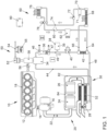
- Figure 1 shows an internal combustion engine 10 with at least one combustion chamber 12, which is intended to drive a motor vehicle.
- the internal combustion engine 10 is designed as a six-cylinder in-line engine. Alternatively, however, other embodiments, preferably with 2 - 12 cylinders, are also possible.
- the internal combustion engine 10 can alternatively be designed as a V-engine or boxer engine.
- the internal combustion engine 10 has a coolant circuit 18, via which the engine block of the internal combustion engine 10 is cooled in order to dissipate the waste heat of the internal combustion engine 10.
- the internal combustion engine 10 is connected with its outlet 14 to an exhaust system 20.
- the exhaust system 20 comprises an exhaust duct 22, in which a turbine of an exhaust gas turbocharger 16 and downstream of the turbine of the exhaust gas turbocharger 16 several exhaust gas aftertreatment components 24, 26 and a heat exchanger 32 of an exhaust gas heat recovery system 30 are arranged.
- the internal combustion engine 10 is designed as a self-igniting diesel engine and the exhaust gas aftertreatment components 24, 26 comprise an oxidation catalyst, a NOx storage catalyst, a particle filter and/or a catalyst for the selective catalytic reduction of nitrogen oxides.
- the exhaust system can also comprise a three-way catalyst or a four-way catalyst.
- an exhaust flap 28 Downstream of the heat exchanger 32, an exhaust flap 28 is provided, with which the exhaust duct 22 can be at least partially closed in order to increase the exhaust back pressure.
- the exhaust aftertreatment components 24, 26 and the heat exchanger 32 can also be arranged as an exhaust heat recovery assembly 84 in a common housing 82 in order to simplify the assembly of the exhaust system 20.
- the exhaust flap 28 can also be integrated into this exhaust heat recovery assembly 84.
- the exhaust heat recovery system 30 comprises, in addition to the heat exchanger 32, which also serves as an evaporator 32 for an operating fluid 39 of the exhaust heat recovery system 30, an expansion engine 34, a condenser 36, a pump 40 and a further heat exchanger 42, which serves to cool a compressed coolant 71 of an air conditioning circuit 60.
- the exhaust heat recovery system 30 further comprises a storage tank 38 for the operating fluid 39, in particular an organic working medium, preferably alcohol or an alcohol-water mixture, particularly preferably ethanol or an ethanol-water mixture.
- the storage tank 38 is connected to the pump 40 via a power line. in which the operating fluid 39 is compressed.
- the compressed operating medium is fed to the further heat exchanger 42, where it absorbs the waste heat of a pressurized coolant 71 and feeds it to the heat exchanger 32 via a feed line 48.
- the waste heat of the exhaust gas flow of the internal combustion engine 10 is transferred to the operating fluid and converts the operating fluid into the gaseous state.
- the steam generated in this process is fed via a steam line 44 to the expansion engine 34, which is operatively connected to a heabride module 50.
- the expansion engine 34 can be connected to a power distribution device 58 either via a mechanical drive shaft 56 to the internal combustion engine 10 or to a motor/generator 52 for generating electrical current.
- the motor/generator 52 is connected to an electrical system 54 of a motor vehicle and can temporarily store the electrical energy in a battery 55.
- a condenser 36 Downstream of the expansion engine 34, a condenser 36 is arranged in the exhaust heat recovery system 30, which has a coolant inlet 46 and a coolant return 47 and is connected to the cooling water circuit 18 of the internal combustion engine 10.
- the operating fluid of the exhaust heat recovery system 30 is converted back into the liquid state before it is fed back to the pump 40 via a return line 49.
- the internal combustion engine 10 can be coupled to an air conditioning compressor 62 of the air conditioning circuit 60 via a traction device, in particular a chain or a belt.
- the air conditioning circuit 60 comprises, in addition to the air conditioning compressor 62, the further heat exchanger 62, a coolant condenser 68, an expansion tank 70 and a coolant evaporator 76.
- the air conditioning compressor 62 is connected to the further heat exchanger 42 via a line 64, where the coolant 71 compressed by the air conditioning compressor 62 transfers its heat to the operating fluid 39 of the exhaust gas heat recovery system 30.
- the further heat exchanger 42 is connected to a coolant condenser 68 of the air conditioning circuit 60 via a further line 66.
- an expansion tank 70 Downstream of the coolant condenser 68, an expansion tank 70 is provided, in which the coolant 71 is stored.
- a high-pressure valve 72 is provided downstream of the expansion tank 70.
- the high-pressure valve 72 is connected via a line 74 to a refrigerant evaporator 76 in which the refrigerant 74 is expanded and evaporated, whereby energy is extracted from the refrigerant 71 so that the refrigerant 71 cools down considerably. This cold is used to air-condition the interior of a motor vehicle.
- the air conditioning circuit contains a Valve 78 and a damping volume 80 are provided to collect the relaxed refrigerant and feed it to the air conditioning compressor 62.
- the air conditioning compressor 62 compresses the coolant 71 to a pressure of at least 20 bar, preferably at least 100 bar, whereby the coolant 71, in particular carbon dioxide, heats up considerably. This heat is transferred via the further heat exchanger 42 to the operating fluid 39 of the exhaust gas heat recovery system 30, whereby the compressed coolant is simultaneously cooled.
- the combustion engine 10 is operatively connected to a control unit 90, via which the air conditioning circuit 60 and the exhaust gas heat recovery system 30 are controlled.
- FIG. 2 A pressure-enthalpy diagram is shown which illustrates the processes in the climate circuit 60.
- FIG. 3 a flow chart for carrying out a method according to the invention for exhaust gas heat recovery is shown.
- the air conditioning compressor 62 is operated and the coolant 71 is compressed.
- the compressed coolant 71 is fed to the further heat exchanger 42 in a method step ⁇ 110>.
- the compressed coolant 71 is cooled by the operating fluid 39 of the exhaust gas heat recovery system 30 and then fed to the coolant condenser 68.
- the coolant 71 is expanded and evaporates in the coolant evaporator 76 in a method step ⁇ 140>.
- the coolant 71 cools down and transfers this cold to an air flow that is fed to the interior of the motor vehicle.
- the expanded coolant is collected again and fed to the air conditioning compressor 62.
- the operating fluid 39 of the exhaust gas heat recovery system 30 is conveyed from the storage tank 38 into the further heat exchanger 42 in a process step ⁇ 200>. There, the hot, compressed coolant 71 transfers its heat to the colder operating fluid 39 in a process step ⁇ 210>, so that energy is supplied to the exhaust gas heat recovery system 30 and removed from the air conditioning circuit 60.
- the process steps ⁇ 120> and ⁇ 210> always run simultaneously.
- the heated operating fluid 39 is fed to the heat exchanger 32, where it is further heated by the exhaust gas flow and evaporates in a process step ⁇ 220>.
- the vaporous operating fluid 39 is fed to the expansion engine 34 via the steam line 44 and drives it in a process step ⁇ 230>.
- the operating fluid 39 is fed to the condenser 36 after flowing through the expansion engine 34, where it is cooled in a process step ⁇ 240> and converted back from the gaseous state to the liquid state.
- the cooled operating fluid is collected in a process step ⁇ 250> and fed back to the pump 40, thus closing the cycle of the exhaust gas heat recovery system.
- the efficiency of the internal combustion engine 10 can be increased, since the dissipated heat can be used and less energy has to be provided to drive the air conditioning compressor through the combustion of fuel.
Description
- Die Erfindung betrifft einen Verbrennungsmotor mit einem Abgaswärmerückgewinnungssystem sowie ein Verfahren zur Abgaswärmerückgewinnung gemäß dem Oberbegriff der unabhängigen Patentansprüche.
- Bei der Entwicklung von Kraftfahrzeugen mit Verbrennungsmotor wird stets nach weiteren Potentialen gesucht, um den Kraftstoffverbrauch zu minimieren und den Wirkungsgrad zu erhöhen. Da bei konventionellen Verbrennungsmotoren ein signifikanter Anteil der Energie ungenutzt über das Abgas in die Umwelt emittiert wird, sind bei Verbrennungsmotoren Systeme zur Abgaswärmerückgewinnung bekannt, mit denen die im Abgasstrom enthaltene Energie zumindest anteilig nutzbar gemacht werden kann. Dazu ist in der Abgasanlage des Verbrennungsmotors ein Wärmetauscher vorgesehen, über welchen die Abwärme des Verbrennungsmotors auf einen Dampfkreislauf übertragen wird, wobei der Dampfkreislauf eine Turbine oder andere Arbeitsmaschinen wie Kolbenexpander oder Scroll-Expander antreibt, über welche diese Energie als mechanische Antriebsleistung und/oder elektrische Energie nutzbar gemacht wird. Ein System zur Abgaswärmerückgewinnung umfasst in der Regel vier Hauptkomponenten: eine Pumpe, einen Verdampfer, einen Expander und einen Kondensator. Der Kondensator des Abgaswärmerückgewinnungssystems wird in der Regel von Kühlwasser zur Kühlung des Verbrennungsmotors durchströmt. In dem Kondensator wird das Arbeitsmedium des Dampfkreislaufs des Abgaswärmerückgewinnungssystems abgekühlt. Dabei muss die Kühlleistung so hoch sein, dass ein sicherer Phasenübergang von dampfförmig zu flüssig stattfindet und zu jeder Zeit gewährleistet ist.
- Entscheidend für den Wirkungsgrad des Clausius-Rankine-Prozesses in dem Abgasrückgewinnungssystem ist eine möglichst große Fläche im zum Prozess gehörigen Temperatur-Entropie-Diagramm. Diese Fläche wird im oberen Bereich über den maximalen Mediendruck und die maximale Temperatur bestimmt. Die Leistung des Expanders in dem Abgasrückgewinnungssystem ist somit abhängig vom Energieangebot der Abwärmequelle. Bei Verbrennungsmotoren ist eine Hauptabwärmequelle das Abgas des Verbrennungsmotors.
- Die Leistungsausbeute des Dampfkreisprozesses in dem Abgaswärmerückgewinnungssystem kann gesteigert werden, indem unterschiedliche Wärmequellen miteinander kombiniert werden und die Abwärme zusätzlich zum Abgas von weiteren Abwärmequellen, insbesondere vom Kühlmittelkreislauf des Verbrennungsmotors zur Verfügung gestellt wird. Die Leistungsausbeute kann ferner gesteigert werden, wenn die Kondensation des dampfförmigen Mediums im Dampfkreisprozess in dem Abgaswärmerückgewinnungssystem durch eine möglichst hohe Kühlleistung des Kondensationsvorgangs gewährleistet wird.
- Aus der
DE 10 2010 023 174 A1 ist ein Abgaswärmerückgewinnungssystem bekannt, welches die Abwärme zweier unterschiedlicher Abwärmequellen, insbesondere die Abwärme des Abgases des Verbrennungsmotors, die Abwärme eines Ladeluftkühlers oder die Abwärme der Motorkühlung nutzt. Diese Abwärme wird zum Erhitzen eines Dampfkreisprozesses in der Abgaswärmerückgewinnung genutzt. - Die
DE 10 2014 016 997 A1 offenbart ein Verfahren und Vorrichtungen zum Betrieb einer einoder mehrstufigen Arbeitsmaschine zur Erzeugung mechanischer Arbeit mit mindestens einem Arbeitskreis mit einem wärmeliefernden Wärmeträgerkreislauf zur Nutzung von zwei und mehr Wärmequellen mit unterschiedlich hohen Temperaturen. Es ist vorgesehen, dass im Wärmeträgerkreislauf dieses Arbeitskreises durch die Vorwärmung, Verdampfung und Überhitzung des Arbeitsfluides das Wärmeträgermedium unter die geforderte Rücklauftemperatur der wärmeliefernden Anlage ausgekühlt wird und mindestens eine Wärmequelle mit einer Temperatur höher als der geforderten Rücklauftemperatur genutzt wird, um die Rücklauftemperatur des Wärmekreislaufes in die wärmeliefernde Anlage wieder zu erreichen. Eine Anwendungsmöglichkeit ergibt sich aus der Nutzung der Abgas- und Motorabwärme von Verbrennungsmotoren. - In der
EP 3 161 275 B1 wird eine Abwärmerückgewinnungsvorrichtung zur Rückgewinnung von Abwärme vorgeschlagen, die während des Betriebs eines Verbrennungsmotors erzeugt wurde, wobei die Abwärmerückgewinnungsvorrichtung eine Wärmekraftmaschine umfasst. - Es ist vorgesehen, dass eine erste Kühlmittelbereitstellungseinrichtung dazu konfiguriert ist, mit einem Kühlmittelkreislauf der Kühlanordnung des Verbrennungsmotors an einer Position stromabwärts von dem Verbrennungsmotor und stromaufwärts von einem Radiator in der Kühlanordnung des Verbrennungsmotors verbunden zu sein.
-
JP 2005 - 282 363 A - Aus der
US 2017 / 0 306 806 A1 ist ein Kühlvorrichtung für ein Abgaswärmerückgewinnungssystem eines Verbrennungsmotors bekannt. Dabei umfasst die Kühlvorrichtung einen ersten Kühlmittelkreislauf und einen zweiten Kühlmittelkreislauf. Eine Kondensatoreinlassleitung leitet Kühlmittel aus einem der Kühlmittelkreisläufe zu einem Kondensator das Abgaswärmerückgewinnungssystems, um die Temperatur des Arbeitsmediums im Kreislauf des Abgaswärmerückgewinnungssystems zu regulieren. - Ferner beschreibt die
WO 2012 / 125 107 A1 ein Abgaswärmerückgewinnungssystem für einen Verbrennungsmotor. Das Abgaswärmerückgewinnungssystem umfasst einen Arbeitskreislauf, in welchem ein Arbeitsmedium verdampft und der Dampf durch eine Turbine entspannt wird, sodass mechanische Energie erzeugt wird. - Die
US 2015 / 0 000 274 A1 beschreibt ein Abgaswärmerückgewinnungssystem nach einem Rankine-Zyklus für ein Abgassystem eines Verbrennungsmotors. Das Abgaswärmerückgewinnungssystem ist mit einem Kältemittelkreislauf einer Klimaanlage des Kraftfahrzeuges gekoppelt, derart, dass zusätzlich die Abwärme eines Klimakondensators der Klimaanlage genutzt werden kann, um die Temperatur eines Arbeitsmittels des Abgaswärmerückgewinnungssystems zu steigern. - Nachteilig an den bekannten Lösungen ist jedoch, dass ein Aufheizen des Trägermediums für den Dampfkreislauf des Abgaswärmerückgewinnungssystems durch die maximale Kühlwassertemperatur des Verbrennungsmotors begrenzt ist. Dadurch ergibt sich ein im Vergleich zur Abgastemperatur geringes Temperaturniveau. Für mobile Anwendungen in Kraftfahrzeugen wird daher ausschließlich die Abwärme des Abgasstroms des Verbrennungsmotors genutzt.
- Aufgabe der Erfindung ist es, den Wirkungsgrad des Abgaswärmerückgewinnungssystems weiter zu erhöhen und die Nachteile der aus dem Stand der Technik bekannten Systeme zu überwinden.
- Erfindungsgemäß wird diese Aufgabe durch einen Verbrennungsmotor mit mindestens einem Brennraum, wobei der Verbrennungsmotor mit seinem Auslass mit einer Abgasanlage verbunden ist, gelöst. In der Abgasanlage ist ein Wärmetauscher eines Abgaswärmerückgewinnungssystems angeordnet, mit welchem die Abwärme des Abgases auf ein Betriebsfluid des Abgaswärmerückgewinnungssystems übertragbar ist. Der Verbrennungsmotor ist ferner mit einem Klimakompressor eines Klimakreislaufs koppelbar. Das Abgaswärmerückgewinnungssystem weist einen weiteren Wärmetauscher auf, in welchem die Abwärme eines verdichteten Kältemittels des Klimakreislaufs auf das Betriebsfluid des Abgaswärmerückgewinnungssystems übertragen wird. Durch die Erwärmung des Betriebsfluids des Abgaswärmerückgewinnungssystems durch die Abwärme des Klimakompressors beziehungsweise des verdichteten Kühlmittels kann zusätzliche Energie in das Abgaswärmerückgewinnungssystem eingebracht werden. Dabei kann sich das Kältemittel in Abhängigkeit von der Verdichtung auf Temperaturen deutlich oberhalb der Kühlwassertemperatur des Verbrennungsmotors erwärmen, wodurch eine stärkere Erwärmung des Betriebsfluids möglich ist. Zudem kann der Leistungsbedarf des Klimakompressors reduziert oder die Kühlleistung erhöht werden, da das verdichtete Kältemittel Wärme auf das Betriebsfluid des Abgaswärmerückgewinnungssystems überträgt und bei der Expansion somit niedrigere Temperatur als ohne Zwischenkühlung erreicht.
- Durch die in den abhängigen Ansprüchen aufgeführten Merkmale sind vorteilhafte Verbesserungen und nicht-triviale Weiterentwicklungen des im unabhängigen Anspruch genannten Verbrennungsmotors möglich.
- In bevorzugter Ausgestaltung der Erfindung ist vorgesehen, dass der weitere Wärmetauscher in einem Betriebsfluidkreislauf des Abgaswärmerückgewinnungssystems stromabwärts einer Pumpe für das Betriebsfluid und stromaufwärts des vom Abgas des Verbrennungsmotors durchströmten Wärmetauscher angeordnet ist. Durch einen Wärmeeintrag stromabwärts der Pumpe kann die Pumpe ein noch verhältnismäßig kühles Betriebsfluid fördern, dadurch ist die Dichte des Betriebsfluids höher und somit auch der Wirkungsgrad der Förderpumpe. Zudem werden Einbußen an der Förderleistung oder Beschädigungen der Pumpe durch Dampfblasenbildung und damit verbundene Kavitation vermieden.
- Erfindungsgemäß ist vorgesehen, dass in einem Betriebsfluidkreislauf des Abgaswärmerückgewinnungssystems eine Expansionskraftmaschine angeordnet ist, über welche ein Motor und/oder Generator antreibbar sind/ist. Durch eine Expansionskraftmaschine, insbesondere eine Turbine, kann die Abwärme des Verbrennungsmotors und die Abwärme des Klimakreislaufs auf einfache Art und Weise nutzbar gemacht werden. Dabei kann die Expansionskraftmaschine zum mechanischen Antrieb eines Nebenaggregats oder des Verbrennungsmotors genutzt werden. Alternativ kann die Expansionskraftmaschine einen Generator antreiben, welcher die Bewegung der Expansionskraftmaschine in elektrische Energie umwandelt. Diese elektrische Energie kann unmittelbar zum Antrieb eines elektrischen Verbrauchers genutzt werden oder in ein Bordnetz eines Kraftfahrzeuges eingespeist beziehungsweise in einer Batterie zwischengespeichert werden.
- Erfindungsgemäß ist dabei vorgesehen, dass die Expansionskraftmaschine über eine Leistungsverzweigungseinrichtung wahlweise mit dem Verbrennungsmotor und/oder mit einem elektrischen Antriebsmotor oder Generator koppelbar ist. Dadurch kann alternativ eine Leistungsübertragung auf den Verbrennungsmotor erfolgen, um ein zusätzliches Antriebsmoment auf die Kurbelwelle zu übertragen und somit die Leistung des Verbrennungsmotors zu erhöhen oder den Verbrauch zu minimieren. In Betriebssituationen, in welchen kein direkter Leistungsbedarf besteht, kann die Energie der Expansionskraftmaschine durch den Generator in elektrische Energie gewandelt und in einer Batterie des Bordnetzes zwischengespeichert werden. Dadurch kann der Generator entlastet werden und/oder das Aufladen der Batterie beschleunigt werden. Zudem können elektrische Verbraucher direkt, also ohne Zwischenspeicherung des elektrischen Stroms in der Batterie, versorgt werden, wodurch die benötigte Antriebsleistung für den Generator reduziert werden kann. Dadurch kann der Wirkungsgrad des Verbrennungsmotors erhöht werden.
- In einer vorteilhaften Ausführungsform der Erfindung ist vorgesehen, dass in dem Betriebsfluidkreislauf des Abgaswärmerückgewinnungssystems stromabwärts der Expansionskraftmaschine und stromaufwärts einer Pumpe für das Betriebsfluid ein Kondensator angeordnet ist. Durch einen Kondensator kann sichergestellt werden, dass das Betriebsfluid nach Durchströmen der Expansionskraftmaschine wieder sicher in seinen flüssigen Aggregatszustand überführt wird.
- In einer vorteilhaften Verbesserung des Abgaswärmerückgewinnungssystems ist vorgesehen, dass der Kondensator einen Kühlmittelzulauf und einen Kühlmittelrücklauf aufweist, welche mit einem Kühlwasserkreislauf des Verbrennungsmotors verbunden sind. Durch einen Anschluss des Kondensators an das Kühlwassersystem des Verbrennungsmotors kann auf einfache Art und Weise ohne zusätzlichen Kühlmittelkreislauf eine effiziente Kühlung des Betriebsfluids erreicht werden, sodass eine Überführung in den flüssigen Aggregatszustand sichergestellt ist. Bevorzugt ist der Kondensator im Kühlwasserkreislauf des Verbrennungsmotors stromabwärts eines Kühlers oder stromaufwärts des Verbrennungsmotors angeordnet, um den Kondensator mit möglichst kühlem Kühlwasser zu durchströmen.
- In einer vorteilhaften Weiterentwicklung der Erfindung ist vorgesehen, dass stromabwärts des Kondensators und stromaufwärts der Pumpe ein Vorratsbehälter für das Betriebsfluid angeordnet ist. Durch einen Vorratsbehälter kann ein Beruhigungsvolumen bereitgestellt werden, in dem sich das Betriebsfluid nach Durchströmen des Kondensators sammeln und beruhigen kann. Dadurch ist eine weitere Abkühlung des Betriebsfluids möglich.
- Gemäß einer bevorzugten Ausführungsform der Erfindung ist vorgesehen, dass das Betriebsfluid des Abgaswärmerückgewinnungssystem ein flüssiges, organisches Arbeitsmedium, insbesondere ein Alkohol, besonders bevorzugt ein Ethanol oder ein Ethanol-Wasser-Gemisch, ist. Ein organisches Arbeitsmedium kann einen niedrigeren Siedepunkt als Wasser aufweisen.
- In weiterer bevorzugter Ausgestaltung der Erfindung ist vorgesehen, dass der Klimakreislauf einen Klimakompressor und einen Kältemittelkondensator aufweist, wobei der weitere Wärmetauscher durch das von dem Klimakompressor verdichtete Kältemittel durchströmt wird, bevor das verdichtete Kältemittel in den Kältemittelkondensator eintritt. Dadurch wird die Wärme des heißen, verdichteten Kältemittels auf das Betriebsfluid des Abgaswärmerückgewinnungssystems übertragen. Dabei kann die gewünschte Abkühlung des Kältemittels dazu genutzt werden, diese Abwärme nicht an die Umwelt zu emittieren, sondern im Abgaswärmerückgewinnungssystem zu nutzen.
- In einer vorteilhaften Ausgestaltung des Klimakreislaufs ist vorgesehen, dass der Klimakreislauf stromabwärts des Kältemittelkondensators und stromaufwärts eines Kältemittelverdampfers einen Ausgleichsbehälter aufweist.
- In einer bevorzugten Ausführungsform der Erfindung ist vorgesehen, dass das Kältemittel des Klimakreislaufs Kohlenstoffdioxid ist. Kohlendioxid ist als Kältemittel für Klimaanlagen vorteilhaft, da es ungiftig und nicht brennbar ist. Allerdings erfordert Kohlenstoffdioxid eine höhere Verdichtung des Kältemittels, wodurch die Temperaturen des komprimierten Kältemittels steigen. Diese höheren Temperaturen führen zu einem höheren Temperaturgradienten zwischen dem Kältemittel und dem Betriebsfluid des Abgaswärmerückgewinnungssystems, was die Wärmeübertragung erhöht und somit ermöglicht, mehr Wärme in das Abgaswärmerückgewinnungssystem einzubringen. Somit kann die Abwärme des Klimakreislaufs insbesondere bei einer Klimaanlage mit Kohlenstoffdioxid als Kältemittel besonders effizient genutzt werden.
- Alternativ ist mit Vorteil vorgesehen, dass das Kältemittel des Klimakreislaufs R1234yf ist. Auch bei bekannten Kältemitteln wie R1234yf werden nach der Kompression im Klimakompressor Temperaturen von mehr als 120 °C erreicht, wodurch auch bei diesen Kältemitteln ein hinreichendes Temperaturgefälle zum Betriebsfluid des Abgaswärmerückgewinnungssystems entsteht.
- Erfindungsgemäß wird ein Verfahren zur Abgaswärmerückgewinnung eines solchen Verbrennungsmotors vorgeschlagen, wobei ein Betriebsfluid des Abgaswärmerückgewinnungssystems in einem ersten Verfahrensschritt durch die Abwärme eines verdichteten Kältemittels des Klimakreislaufs und in einem zweiten Verfahrensschritt durch die Abwärme des Abgases des Verbrennungsmotors erhitzt wird. Durch ein solches Verfahren kann die Abwärme des Klimakreislaufs genutzt werden, um zusätzliche Energie in das Abgaswärmerückgewinnungssystem einzuspeisen. Dabei werden in dem Klimakreislauf Temperaturen erreicht, welche oberhalb der Temperatur des Kühlwasserkreislaufs des Verbrennungsmotors liegen, wodurch das Verdampfen des Betriebsfluids begünstigt wird.
- In einer vorteilhaften Ausführungsvariante des Verfahrens ist vorgesehen, dass das Kältemittel auf einen Betriebsdruck von mindestens 20 bar, vorzugsweise von mindestens 100 bar, verdichtet wird. Je stärker die Kompression des Kältemittels, desto höher sind die Temperaturen, die nach der Kompression erreicht werden. Insbesondere bei Kohlenstoffdioxid als Kältemittel sind hohe Kompressionsdrücke von 100 bar und mehr notwendig, um eine hinreichende Kühlleistung der Klimaanlage zu realisieren. Gerade bei Kältemitteln, welche so stark verdichtet werden und damit sehr hohe Temperaturen erreichen, ist die Übertragung der Abwärme auf das Betriebsfluid des Abgaswärmerückgewinnungssystems vorteilhaft.
- In einer weiteren vorteilhaften Ausgestaltung des Verfahrens ist vorgesehen, dass die Abwärme des verdichteten Kältemittels stromabwärts einer Pumpe auf das Betriebsfluid des Abgaswärmerückgewinnungssystems übertragen wird. Unmittelbar stromabwärts der Pumpe des Klimakreislaufes erreicht das Kältemittel seine höchste Verdichtung und damit verbunden seine höchste Temperatur. Somit besteht hier das größte Potenzial, diese Abwärme nutzbar zu machen und das verdichtete Kältemittel abzukühlen, bevor das Kältemittel durch den Kondensator und den Verdampfer geleitet und entspannt wird.
- In einer bevorzugten Ausgestaltung des Verfahrens ist vorgesehen, dass ein Klimakompressor des Klimakreislaufs mittels eines Zugmittels, insbesondere einer Kette oder eines Riemens, von einer rotierenden Welle des Verbrennungsmotors angetrieben wird. Durch ein Zugmittel ist ein einfacher Antrieb des Klimakompressors durch den Verbrennungsmotor möglich. Dabei ist keine zusätzliche Umwandlung der mechanischen Energie in elektrische Energie und zurück notwendig, wodurch die Verlustleistung minimiert werden kann. Alternativ kann der Klimakompressor auch elektrisch angetrieben werden, wobei der elektrische Strom insbesondere durch die Expansionskraftmaschine in dem Abgaswärmerückgewinnungssystem und einem damit verbundenen Generator bereitgestellt werden kann.
- Besonders bevorzugt ist dabei, wenn eine schaltbare Kupplung, insbesondere eine Magnetkupplung zwischen dem Riementrieb und dem Klimakompressor vorgesehen ist, wobei der Klimakompressor in einem ersten Betriebszustand der schaltbaren Kupplung von der rotierenden Welle des Verbrennungsmotors angetrieben wird und in einem zweiten Betriebszustand der schaltbaren Kupplung von der rotierenden Welle des Verbrennungsmotors abgekuppelt ist. Dadurch kann der Klimakompressor vom Antriebsstrang entkoppelt werden und die Antriebsleistung reduziert werden, wenn der Klimakompressor abgeschaltet ist.
- Die verschiedenen in dieser Anmeldung genannten Ausführungsformen der Erfindung sind, sofern im Einzelfall nicht anders ausgeführt, mit Vorteil miteinander kombinierbar.
- Die Erfindung wird nachfolgend in Ausführungsbeispielen anhand der zugehörigen Zeichnungen erläutert. Gleiche Bauteile oder Bauteile mit gleicher Funktion sind dabei in den unterschiedlichen Figuren mit gleichen Bezugszeichen versehen. Es zeigen:
- Figur 1
- ein bevorzugtes Ausführungsbeispiel eines Verbrennungsmotors mit einer Abgasanlage, einem Abgaswärmerückgewinnungssystem sowie einem Klimakreislauf;
- Figur 2
- ein Diagramm zum Druck in Bezug auf die Enthalpie im Klimakreislauf bei einem erfindungsgemäßen Verbrennungsmotor; und
- Figur 3
- ein Ablaufdiagramm zur Durchführung eines erfindungsgemäßen Verfahrens zur Abgaswärmerückgewinnung eines Verbrennungsmotors.
-
Figur 1 zeigt einen Verbrennungsmotor 10 mit mindestens einem Brennraum 12, welcher zum Antrieb eines Kraftfahrzeuges vorgesehen ist. InFigur 1 ist der Verbrennungsmotor 10 als Sechszylinder-Reihenmotor ausgeführt. Alternativ sind jedoch auch andere Ausführungsformen, vorzugsweise mit 2 - 12 Zylindern, möglich. Der Verbrennungsmotor 10 kann alternativ auch als V-Motor oder Boxermotor ausgeführt werden. Der Verbrennungsmotor 10 weist einen Kühlmittelkreislauf 18 auf, über welchen der Motorblock des Verbrennungsmotors 10 gekühlt wird, um die Abwärme des Verbrennungsmotors 10 abzuführen. Der Verbrennungsmotor 10 ist mit seinem Auslass 14 mit einer Abgasanlage 20 verbunden. Die Abgasanlage 20 umfasst einen Abgaskanal 22, in welchem in Strömungsrichtung eines Abgases des Verbrennungsmotors 10 durch den Abgaskanal 22 eine Turbine eines Abgasturboladers 16 und stromabwärts der Turbine des Abgasturboladers 16 mehrere Abgasnachbehandlungskomponenten 24, 26 sowie ein Wärmetauscher 32 eines Abgaswärmerückgewinnungssystems 30 angeordnet sind. In einer bevorzugten Ausführungsform der Erfindung ist der Verbrennungsmotor 10 als selbstzündender Dieselmotor ausgeführt und die Abgasnachbehandlungskomponenten 24, 26 umfassen einen Oxidationskatalysator, einen NOx-Speicherkatalysator, einen Partikelfilter und/oder einen Katalysator zur selektiven katalytischen Reduktion von Stickoxiden. - Alternativ oder zusätzlich kann die Abgasanlage, insbesondere bei einem Ottomotor, auch einen Drei-Wege-Katalysator oder einen Vier-Wege-Katalysator umfassen. Stromabwärts des Wärmetauschers 32 ist eine Abgasklappe 28 vorgesehen, mit welcher der Abgaskanal 22 zumindest teilweise verschlossen werden kann, um den Abgasgegendruck zu erhöhen. Die Abgasnachbehandlungskomponenten 24, 26 und der Wärmetauscher 32 können als Abgaswärmerückgewinnungsbaugruppe 84 auch in einem gemeinsamen Gehäuse 82 angeordnet werden, um die Montage der Abgasanlage 20 zu vereinfachen. Die Abgasklappe 28 kann ebenfalls in diese Abgaswärmerückgewinnungsbaugruppe 84 integriert werden.
- Das Abgaswärmerückgewinnungssystem 30 umfasst neben dem Wärmetauscher 32, welcher auch als Verdampfer 32 für ein Betriebsfluid 39 des Abgaswärmrückgewinnungssystems 30 dient, eine Expansionskraftmaschine 34, einen Kondensator 36, eine Pumpe 40 sowie einen weiteren Wärmetauscher 42, welcher zur Abkühlung eines verdichteten Kältemittels 71 eines Klimakreislaufs 60 dient. Das Abgaswärmerückgewinnungssystem 30 umfasst ferner einen Vorratsbehälter 38 für das Betriebsfluid 39, insbesondere ein organisches Arbeitsmedium, bevorzugt Alkohol oder ein Alkohol-Wasser-Gemisch, besonders bevorzugt Ethanol oder ein Ethanol-Wasser-Gemisch. Der Vorratsbehälter 38 ist über eine Leistung mit der Pumpe 40 verbunden, in welcher das Betriebsfluid 39 verdichtet wird. Das verdichtete Betriebsmedium wird dem weiteren Wärmetauscher 42 zugeführt, wo es die Abwärme eines unter Druck stehenden Kältemittels 71 aufnimmt und über eine Zuführleitung 48 dem Wärmetauscher 32 zuführt. Im Wärmetauscher 32 wird die Abwärme des Abgasstroms des Verbrennungsmotors 10 auf das Betriebsfluid übertragen und überführt das Betriebsfluid in den gasförmigen Aggregatszustand. Der dabei entstehende Dampf wird über eine Dampfleitung 44 der Expansionskraftmaschine 34 zugeführt, welche mit einem Heabrid-Modul 50 in Wirkverbindung steht. Die Expansionskraftmaschine 34 ist mit einer Leistungsverzweigungseinrichtung 58 wahlweise über eine mechanische Antriebswelle 56 mit dem Verbrennungsmotor 10 oder mit einem Motor/Generator 52 zur Erzeugung von elektrischem Strom verbindbar. Der Motor/Generator 52 ist mit einem elektrischen Bordnetz 54 eines Kraftfahrzeuges verbunden und kann die elektrische Energie in einer Batterie 55 zwischenspeichern.
- Stromabwärts der Expansionskraftmaschine 34 ist in dem Abgaswärmerückgewinnungssystem 30 ein Kondensator 36 angeordnet, welcher einen Kühlmittelzulauf 46 und einen Kühlmittelrücklauf 47 aufweist und an den Kühlwasserkreislauf 18 des Verbrennungsmotors 10 angeschlossen ist. In dem Kondensator 36 wird das Betriebsfluid des Abgaswärmerückgewinnungssystems 30 wieder in den flüssigen Aggregatzustand überführt, bevor es über eine Rücklaufleitung 49 wieder der Pumpe 40 zugeführt wird.
- Der Verbrennungsmotor 10 ist über ein Zugmittel, insbesondere eine Kette oder einen Riemen, mit einem Klimakompressor 62 des Klimakreislaufs 60 koppelbar. Der Klimakreislauf 60 umfasst neben dem Klimakompressor 62 den weiteren Wärmetauscher 62, einen KältemittelKondensator 68, einen Ausgleichsbehälter 70 und einen Kältemittelverdampfer 76. Der Klimakompressor 62 ist über ein Leitung 64 mit dem weiteren Wärmetauscher 42 verbunden, wo das durch den Klimakompressor 62 verdichtete Kältemittel 71 seine Wärme auf das Betriebsfluid 39 des Abgaswärmerückgewinnungssystems 30 überträgt. Der weitere Wärmetauscher 42 ist über eine weitere Leitung 66 mit einem Kältemittel-Kondensator 68 des Klimakreislaufs 60 verbunden. Stromabwärts des Kältemittel-Kondensators 68 ist ein Ausgleichsbehälter 70 vorgesehen, in welchem das Kältemittel 71 bevorratet ist. Stromabwärts des Ausgleichsbehälters 70 ist ein Hochdruck-Ventil 72 vorgesehen. Das Hochdruck-Ventil 72 ist über eine Leitung 74 mit einem Kältemittelverdampfer 76 verbunden, in welchem das Kältemittel 74 entspannt und verdampft wird, wobei dem Kältemittel 71 Energie entzogen wird, sodass sich das Kältemittel 71 stark abkühlt. Diese Kälte wird zur Klimatisierung eines Fahrzeuginnenraums eines Kraftfahrzeuges genutzt. Ferner sind in dem Klimakreislauf ein Ventil 78 sowie ein Dämpfungsvolumen 80 vorgesehen, um das entspannte Kältemittel wieder zu sammeln und dem Klimakompressor 62 zuzuführen.
- Der Klimakompressor 62 verdichtet das Kältemittel 71 auf einen Druck von mindestens 20 bar, vorzugsweise von mindestens 100 bar, wobei sich das Kältemittel 71, insbesondere Kohlenstoffdioxid, stark erwärmt. Diese Wärme wird über den weiteren Wärmetauscher 42 auf das Betriebsfluid 39 des Abgaswärmerückgewinnungssystems 30 übertragen, wobei das verdichtete Kältemittel gleichzeitig abgekühlt wird.
- Der Verbrennungsmotor 10 steht mit einem Steuergerät 90 in Wirkverbindung, über welches der Klimakreislauf 60 sowie das Abgaswärmerückgewinnungssystem 30 gesteuert werden.
- In
Figur 2 ist ein Druck-Enthalpie-Diagramm dargestellt, welches die Vorgänge im Klimakreislauf 60 darstellt. - In
Figur 3 ist ein Ablaufdiagramm zur Durchführung eines erfindungsgemäßen Verfahrens zur Abgaswärmerückgewinnung dargestellt. In einem ersten Verfahrensschritt <100> wird der Klimakompressor 62 betrieben und das Kältemittel 71 verdichtet. Das verdichtete Kältemittel 71 wird in einem Verfahrensschritt <110> dem weiteren Wärmetauscher 42 zugeführt. In einem Verfahrensschritt <120> wird das verdichtete Kältemittel 71 durch das Betriebsfluid 39 des Abgaswärmerückgewinnungssystems 30 abgekühlt und anschließend dem KältemittelKondensator 68 zugeführt. In einem Verfahrensschritt <130> wird das Kältemittel 71 entspannt und verdampft in einem Verfahrensschritt <140> in dem Kältemittelverdampfer 76. Dabei kühlt sich das Kältemittel 71 ab und überträgt diese Kälte auf einen Luftstrom, der dem Fahrzeuginnenraum des Kraftfahrzeuges zugeführt wird. In einem Verfahrensschritt <150> wird das entspannte Kältemittel wieder gesammelt und dem Klimakompressor 62 zugeführt. - Das Betriebsfluid 39 des Abgaswärmerückgewinnungssystems 30 wird in einem Verfahrensschritt <200> aus dem Vorratsbehälter 38 in den weiteren Wärmetauscher 42 gefördert. Dort überträgt das heiße, komprimierte Kältemittel 71 in einem Verfahrensschritt <210> seine Wärme auf das kältere Betriebsfluid 39, sodass dem Abgaswärmerückgewinnungssystem 30 Energie zugeführt und dem Klimakreislauf 60 entzogen wird. Dabei laufen die Verfahrensschritte <120> und <210> stets gleichzeitig ab. Das erwärmte Betriebsfluid 39 wird dem Wärmetauscher 32 zugeführt, wo es durch den Abgasstrom weiter erhitzt wird und in einem Verfahrensschritt <220> verdampft. Das dampfförmige Betriebsfluid 39 wird über die Dampfleitung 44 der Expansionskraftmaschine 34 zugeführt und treibt diese in einem Verfahrensschritt <230> an. Das Betriebsfluid 39 wird nach Durchströmen der Expansionskraftmaschine 34 dem Kondensator 36 zugeführt, wobei es in einem Verfahrensschritt <240> abgekühlt und wieder vom gasförmigen Aggregatszustand in den flüssigen Aggregatszustand überführt wird. Das abgekühlte Betriebsfluid wird in einem Verfahrensschritt <250> gesammelt und wieder der Pumpe 40 zugeführt, womit sich der Kreislauf des Abgaswärmerückgewinnungssystems schließt.
- Durch die zusätzliche Übertragung der Abwärme des verdichteten Kältemittels 71 auf das Betriebsfluid 39 des Abgaswärmerückgewinnungssystems 30 lässt sich der Wirkungsgrad des Verbrennungsmotors 10 steigern, da die abgeführte Wärme genutzt werden kann und weniger Energie zum Antrieb des Klimakompressors durch die Verbrennung von Kraftstoff bereitgestellt werden muss.
-
- 10
- Verbrennungsmotor
- 12
- Brennraum
- 14
- Auslass
- 16
- Abgasturbolader
- 18
- Turbine
- 20
- Abgasanlage
- 22
- Abgaskanal
- 24
- erste Abgasnachbehandlungskomponente
- 26
- zweite Abgasnachbehandlungskomponente
- 28
- Abgasklappe
- 30
- Abgaswärmerückgewinnungssystem
- 32
- Wärmetauscher / Verdampfer
- 34
- Expansionskraftmaschine
- 36
- Kondensator
- 38
- Vorratsbehälter
- 39
- Betriebsfluid WHR (Waste-Heat-Recovery) -System
- 40
- Pumpe
- 42
- Wärmetauscher / Klima-Kondensator
- 44
- Dampfleitung
- 46
- Kühlmittelzulauf
- 47
- Kühlmittelrücklauf
- 48
- Zuführleitung
- 49
- Rücklaufleitung
- 50
- Heabrid-Modul
- 52
- Motor / Generator
- 54
- elektrisches Bordnetz
- 55
- Batterie
- 56
- mechanischer Antrieb
- 58
- Leistungsverzweigungseinrichtung
- 60
- Klimakreislauf
- 62
- Klima-Kompressor
- 64
- Leitung
- 66
- weitere Leitung
- 68
- Kältemittel-Kondensator
- 70
- Ausgleichsbehälter
- 71
- Kältemittel
- 72
- High-Druck-Ventil
- 74
- Leitung
- 76
- Kältemittelverdampfer
- 78
- Ventil
- 80
- Dämpfung
- 82
- Gehäuse
- 84
- AWR-Baugruppe
- 90
- Steuergerät
Claims (13)
- Verbrennungsmotor (10) mit mindestens einem Brennraum (12), wobei der Verbrennungsmotor (10) mit seinem Auslass (14) mit einer Abgasanlage (20) verbunden ist, wobei in der Abgasanlage (20) ein Wärmetauscher (32) eines Abgaswärmerückgewinnungssystems (30) angeordnet ist, mit welchem die Abwärme des Abgases auf ein Betriebsfluid (39) des Abgaswärmerückgewinnungssystems (30) übertragbar ist, wobei das Abgaswärmerückgewinnungssystem (30) einen weiteren Wärmetauscher (42) aufweist, in welchem die Abwärme eines verdichteten Kältemittels (71) eines Klimakreislaufs (60) auf das Betriebsfluid (39) des Abgaswärmerückgewinnungssystems (30) übertragbar ist, und wobei in einem Betriebsfluidkreis des Abgaswärmerückgewinnungssystems (30) eine Expansionskraftmaschine (34) angeordnet ist, über welche ein Motor (10) und/oder ein Generator (52) antreibbar ist, dadurch gekennzeichnet, dass die Expansionskraftmaschine (34) über eine Leistungsverzweigungseinrichtung (58) wahlweise mit dem Verbrennungsmotor (10) und/oder mit einem elektrischen Antriebsmotor (52) oder Generator (52) koppelbar ist.
- Verbrennungsmotor (10) nach Anspruch 1, dadurch gekennzeichnet, dass der weitere Wärmetauscher (42) in einem Betriebsfluidkreislauf des Abgaswärmerückgewinnungssystems (30) stromabwärts einer Pumpe (40) für das Betriebsfluid (39) und stromaufwärts des vom Abgas des Verbrennungsmotors (10) durchströmten Wärmetauschers (32) angeordnet ist.
- Verbrennungsmotor (10) nach Anspruch 1 oder 2, dadurch gekennzeichnet, dass in dem Betriebsfluidkreislauf des Abgaswärmerückgewinnungssystems (30) stromabwärts der Expansionskraftmaschine (34) und stromaufwärts einer Pumpe (40) für das Betriebsfluid (39) ein Kondensator (36) angeordnet ist.
- Verbrennungsmotor (10) nach Anspruch 3, dadurch gekennzeichnet, dass der Kondensator (36) einen Kühlmittelzulauf (46) und einen Kühlmittelrücklauf (47) aufweist, welche mit einem Kühlwasserkreislauf (18) des Verbrennungsmotors (10) verbunden sind.
- Verbrennungsmotor (10) nach Anspruch 3 oder 4, dadurch gekennzeichnet, dass stromabwärts des Kondensators (36) und stromaufwärts der Pumpe (40) ein Vorratsbehälter (38) für das Betriebsfluid (39) angeordnet ist.
- Verbrennungsmotor (10) nach einem der Ansprüche 1 bis 5, dadurch gekennzeichnet, dass das Betriebsfluid (39) des Abgaswärmerückgewinnungssystems (30) ein Alkohol, insbesondere Ethanol, ist.
- Verbrennungsmotor (10) nach einem der Ansprüche 1 bis 6, dadurch gekennzeichnet, dass der Klimakreislauf (60) einen Klimakompressor (62) und einen Kältemittelkondensator (68) aufweist, wobei der weitere Wärmetauscher (42) durch das von dem Klimakompressor (62) verdichtete Kältemittel (71) durchströmt wird, bevor das verdichtete Kältemittel (71) in den Kältemittelkondensator (68) eintritt.
- Verbrennungsmotor (10) nach einem der Ansprüche 1 bis 7, dadurch gekennzeichnet, dass der Klimakreislauf (60) stromabwärts des Kältemittelkondensators (68) und stromaufwärts eines Kältemittelverdampfers (76) einen Ausgleichsbehälter (70) aufweist.
- Verbrennungsmotor (10) nach einem der Ansprüche 1 bis 8, dadurch gekennzeichnet, dass das Kältemittel (71) des Klimakreislaufs (60) Kohlenstoffdioxid ist.
- Verfahren zur Abgaswärmerückgewinnung eines Verbrennungsmotor (10) nach einem der Ansprüche 1 bis 9, dadurch gekennzeichnet, dass ein Betriebsfluid (39) des Abgaswärmerückgewinnungssystems (30) in einem ersten Verfahrensschritt durch die Abwärme eines verdichteten Kältemittels (71) des Klimakreislaufs (60) und in einem zweiten Verfahrensschritt durch die Abwärme des Abgases des Verbrennungsmotors (10) erhitzt wird.
- Verfahren zur Abgaswärmerückgewinnung eines Verbrennungsmotors (10) nach Anspruch 10, dadurch gekennzeichnet, dass das Kältemittel (71) auf einen Betriebsdruck von mindestens 20 bar, vorzugsweise von mindestens 100 bar, verdichtet wird.
- Verfahren zur Abgaswärmerückgewinnung eines Verbrennungsmotors (10) nach Anspruch 10 oder 11, dadurch gekennzeichnet, dass die Abwärme des verdichteten Kältemittels (71) stromabwärts einer Pumpe (40) auf das Betriebsfluid des Abgaswärmerückgewinnungssystems (10) übertragen wird.
- Verfahren zur Abgaswärmerückgewinnung eines Verbrennungsmotors (10) nach einem der Ansprüche 10 bis 12, dadurch gekennzeichnet, dass ein Klimakompressor (62) des Klimakreislaufs (60) mittels eines Zugmittels, insbesondere einer Kette oder eines Riemens, von einer rotierenden Welle des Verbrennungsmotors (10) angetrieben wird.
Applications Claiming Priority (1)
| Application Number | Priority Date | Filing Date | Title |
|---|---|---|---|
| DE102019115909.1A DE102019115909A1 (de) | 2019-06-12 | 2019-06-12 | Verbrennungsmotor mit Abgaswärmerückgewinnungssystem sowie Verfahren zur Abgaswärmerückgewinnung |
Publications (2)
| Publication Number | Publication Date |
|---|---|
| EP3751107A1 EP3751107A1 (de) | 2020-12-16 |
| EP3751107B1 true EP3751107B1 (de) | 2024-04-10 |
Family
ID=71119911
Family Applications (1)
| Application Number | Title | Priority Date | Filing Date |
|---|---|---|---|
| EP20179402.1A Active EP3751107B1 (de) | 2019-06-12 | 2020-06-11 | Verbrennungsmotor mit abgaswärmerückgewinnungssystem sowie verfahren zur abgaswärmerückgewinnung |
Country Status (3)
| Country | Link |
|---|---|
| US (1) | US11035270B2 (de) |
| EP (1) | EP3751107B1 (de) |
| DE (1) | DE102019115909A1 (de) |
Families Citing this family (1)
| Publication number | Priority date | Publication date | Assignee | Title |
|---|---|---|---|---|
| DE102021114792B4 (de) | 2021-06-09 | 2023-02-02 | Audi Aktiengesellschaft | Elektrofahrzeug mit Energierückgewinnungssystem |
Citations (1)
| Publication number | Priority date | Publication date | Assignee | Title |
|---|---|---|---|---|
| US20150000274A1 (en) * | 2013-06-28 | 2015-01-01 | Cummins Inc. | Waste heat recovery system including connection to a vehicle air conditioning system |
Family Cites Families (21)
| Publication number | Priority date | Publication date | Assignee | Title |
|---|---|---|---|---|
| US5351487A (en) * | 1992-05-26 | 1994-10-04 | Abdelmalek Fawzy T | High efficiency natural gas engine driven cooling system |
| WO2001053667A1 (en) * | 2000-01-21 | 2001-07-26 | Honda Giken Kogyo Kabushiki Kaisha | Combustion gas purifier and internal combustion engine |
| JP4140544B2 (ja) | 2004-03-26 | 2008-08-27 | 株式会社デンソー | 廃熱利用装置 |
| DE102005024685A1 (de) | 2004-05-31 | 2005-12-29 | Denso Corp., Kariya | Wärmekreis |
| US20090211253A1 (en) * | 2005-06-16 | 2009-08-27 | Utc Power Corporation | Organic Rankine Cycle Mechanically and Thermally Coupled to an Engine Driving a Common Load |
| JP2009167994A (ja) * | 2008-01-21 | 2009-07-30 | Sanden Corp | 内燃機関の廃熱利用装置 |
| US8393171B2 (en) * | 2010-04-13 | 2013-03-12 | Gerald Allen Alston | Mechanically enhanced ejector HVAC and electric power generation system |
| DE102010023174A1 (de) | 2010-06-09 | 2011-12-15 | Georg Beckmann | Verfahren und Einrichtung zur Nutzung der Abwärmen von Verbrennungskraftmaschinen mittels eines Dampfkreislaufes |
| DE102012000100A1 (de) | 2011-01-06 | 2012-07-12 | Cummins Intellectual Property, Inc. | Rankine-kreisprozess-abwärmenutzungssystem |
| SE535680C2 (sv) * | 2011-03-17 | 2012-11-06 | Scania Cv Ab | Arrangemang för att omvandla värmeenergi till mekanisk energi i ett fordon |
| JP5804879B2 (ja) * | 2011-09-30 | 2015-11-04 | 日産自動車株式会社 | 廃熱利用装置 |
| CH708685A2 (de) * | 2013-10-14 | 2015-04-15 | Weidmann Plastics Tech Ag | Kraftfahrzeug mit einer Klimaanlage. |
| JP6387245B2 (ja) * | 2014-05-15 | 2018-09-05 | 日産自動車株式会社 | エンジンの廃熱利用装置 |
| EP3161275B1 (de) | 2014-06-26 | 2018-12-19 | Volvo Truck Corporation | Abwärmerückgewinnungsvorrichtung |
| US10801372B2 (en) | 2014-10-31 | 2020-10-13 | Modine Manufacturing Company | Cooling module and method for rejecting heat from a coupled engine system and rankine cycle waste heat recovery system |
| DE102014016997A1 (de) | 2014-11-18 | 2016-05-19 | Klaus-Peter Priebe | Mehrstufiges Verfahren zur Nutzung von zwei und mehr Wärmequellen zum Betrieb einer ein- oder mehrstufigen Arbeitsmaschine, Vorwärmung RL-Motorkühlung |
| SE538835C2 (en) * | 2014-12-05 | 2016-12-20 | Scania Cv Ab | A cooling arrangement for a WHR system |
| FR3030702B1 (fr) * | 2014-12-17 | 2019-09-13 | Valeo Systemes Thermiques | Circuit de gestion thermique d'un vehicule automobile et procede de pilotage associe |
| US10914201B2 (en) * | 2015-12-18 | 2021-02-09 | Cummins Inc. | Integrated cooling system for engine and waste heat recovery |
| SE539690C2 (en) * | 2016-02-04 | 2017-10-31 | Scania Cv Ab | A method for controlling a waste heat recovery system and such a waste heat recovery system |
| US11607928B2 (en) * | 2017-03-10 | 2023-03-21 | Mobile Climate Control, Corp. | Method and apparatus for cooling an air conditioning system controller |
-
2019
- 2019-06-12 DE DE102019115909.1A patent/DE102019115909A1/de active Pending
-
2020
- 2020-06-11 EP EP20179402.1A patent/EP3751107B1/de active Active
- 2020-06-11 US US16/899,563 patent/US11035270B2/en active Active
Patent Citations (1)
| Publication number | Priority date | Publication date | Assignee | Title |
|---|---|---|---|---|
| US20150000274A1 (en) * | 2013-06-28 | 2015-01-01 | Cummins Inc. | Waste heat recovery system including connection to a vehicle air conditioning system |
Also Published As
| Publication number | Publication date |
|---|---|
| DE102019115909A1 (de) | 2020-12-17 |
| US11035270B2 (en) | 2021-06-15 |
| EP3751107A1 (de) | 2020-12-16 |
| US20200392883A1 (en) | 2020-12-17 |
Similar Documents
| Publication | Publication Date | Title |
|---|---|---|
| EP1549827B1 (de) | Verfahren und einrichtung zur rückgewinnung von energie | |
| DE102011012584B4 (de) | Fahrzeug-Abwärmerückgewinnungssystem | |
| EP1830046B1 (de) | Antriebseinheit mit wärmerückgewinnung | |
| DE102006043139B4 (de) | Vorrichtung zur Gewinnung von mechanischer oder elektrischer Energie aus der Abwärme eines Verbrennungsmotors eines Kraftfahrzeugs | |
| DE102005049831B4 (de) | Dampfkompressionskühlvorrichtung | |
| EP2686526B1 (de) | Verfahren zum betreiben eines dampfkreisprozesses | |
| EP2196661A2 (de) | Antriebseinheit mit Kühlkreislauf und separatem Wärmerückgewinnungskreislauf | |
| DE102006043835A1 (de) | Wärmetauscheranordnung | |
| DE102010003906A1 (de) | Verbrennungsmotor | |
| DE102010049916A1 (de) | Verfahren und Vorrichtung zur Abwärmenutzung aus einem Abgasstrom einer Verbrennungskraftmaschine | |
| WO2012055555A2 (de) | Brennkraftmaschine | |
| DE102014019097A1 (de) | Vorrichtung zur Ladeluftkühlung und Fahrzeug mit einer solchen Vorrichtung | |
| EP2020316A1 (de) | Speicher zum Kühlen eines zur Motoraufladung vorgesehenen im wesentlichen gasförmigen Fluids | |
| EP3751107B1 (de) | Verbrennungsmotor mit abgaswärmerückgewinnungssystem sowie verfahren zur abgaswärmerückgewinnung | |
| DE102016218764A1 (de) | Brennkraftmaschine eines Kraftfahrzeugs mit einer Abwärmenutzungseinrichtung | |
| DE102010025186A1 (de) | Abwärmenutzungsvorrichtung, Brennkraftmaschine und Kraftfahrzeug | |
| DE102013011521A1 (de) | Antriebseinheit für ein Kraftfahrzeug | |
| DE202017100590U1 (de) | System zur Wärmerückgewinnung und Ladeluftverdichtung | |
| DE102012222082A1 (de) | Vorrichtung und Verfahren zur Abwärmenutzung einer Brennkraftmaschine | |
| DE102017011851A1 (de) | Anordnung zur Umwandlung thermischer Energie aus Verlustwärme einer Verbrennungskraftmaschine | |
| DE102011109384A1 (de) | Brennkraftmaschine mit einer Wärmerückgewinnungsvorrichtung und Verfahren zum Betrieb einer Brennkraftmaschine | |
| DE102008053066A1 (de) | System mit einem Rankine-Kreislauf | |
| DE102018004554A1 (de) | Temperiereinrichtung für ein Hybridfahrzeug | |
| DE102013205239A1 (de) | Fahrzeugantrieb mit einer eine Verlustwärme nutzenden Expansionsmaschine und Verfahren zum Betreiben eines solchen Fahrzeugantriebs | |
| EP2733339B1 (de) | Vorrichtung zur Nutzung der Abwärme einer Brennkraftmaschine |
Legal Events
| Date | Code | Title | Description |
|---|---|---|---|
| PUAI | Public reference made under article 153(3) epc to a published international application that has entered the european phase |
Free format text: ORIGINAL CODE: 0009012 |
|
| STAA | Information on the status of an ep patent application or granted ep patent |
Free format text: STATUS: THE APPLICATION HAS BEEN PUBLISHED |
|
| AK | Designated contracting states |
Kind code of ref document: A1 Designated state(s): AL AT BE BG CH CY CZ DE DK EE ES FI FR GB GR HR HU IE IS IT LI LT LU LV MC MK MT NL NO PL PT RO RS SE SI SK SM TR |
|
| AX | Request for extension of the european patent |
Extension state: BA ME |
|
| STAA | Information on the status of an ep patent application or granted ep patent |
Free format text: STATUS: REQUEST FOR EXAMINATION WAS MADE |
|
| 17P | Request for examination filed |
Effective date: 20210616 |
|
| RBV | Designated contracting states (corrected) |
Designated state(s): AL AT BE BG CH CY CZ DE DK EE ES FI FR GB GR HR HU IE IS IT LI LT LU LV MC MK MT NL NO PL PT RO RS SE SI SK SM TR |
|
| STAA | Information on the status of an ep patent application or granted ep patent |
Free format text: STATUS: EXAMINATION IS IN PROGRESS |
|
| 17Q | First examination report despatched |
Effective date: 20220103 |
|
| GRAP | Despatch of communication of intention to grant a patent |
Free format text: ORIGINAL CODE: EPIDOSNIGR1 |
|
| STAA | Information on the status of an ep patent application or granted ep patent |
Free format text: STATUS: GRANT OF PATENT IS INTENDED |
|
| INTG | Intention to grant announced |
Effective date: 20231108 |
|
| GRAS | Grant fee paid |
Free format text: ORIGINAL CODE: EPIDOSNIGR3 |
|
| GRAA | (expected) grant |
Free format text: ORIGINAL CODE: 0009210 |
|
| STAA | Information on the status of an ep patent application or granted ep patent |
Free format text: STATUS: THE PATENT HAS BEEN GRANTED |
|
| AK | Designated contracting states |
Kind code of ref document: B1 Designated state(s): AL AT BE BG CH CY CZ DE DK EE ES FI FR GB GR HR HU IE IS IT LI LT LU LV MC MK MT NL NO PL PT RO RS SE SI SK SM TR |
|
| REG | Reference to a national code |
Ref country code: GB Ref legal event code: FG4D Free format text: NOT ENGLISH |