EP3751069B1 - Système de fixation pour fixer des panneaux composites à structure en sandwich à une structure de support - Google Patents
Système de fixation pour fixer des panneaux composites à structure en sandwich à une structure de support Download PDFInfo
- Publication number
- EP3751069B1 EP3751069B1 EP19179936.0A EP19179936A EP3751069B1 EP 3751069 B1 EP3751069 B1 EP 3751069B1 EP 19179936 A EP19179936 A EP 19179936A EP 3751069 B1 EP3751069 B1 EP 3751069B1
- Authority
- EP
- European Patent Office
- Prior art keywords
- fastening system
- sleeve
- face skin
- sandwich
- fastening
- Prior art date
- Legal status (The legal status is an assumption and is not a legal conclusion. Google has not performed a legal analysis and makes no representation as to the accuracy of the status listed.)
- Active
Links
Images

Classifications
-
- E—FIXED CONSTRUCTIONS
- E04—BUILDING
- E04F—FINISHING WORK ON BUILDINGS, e.g. STAIRS, FLOORS
- E04F13/00—Coverings or linings, e.g. for walls or ceilings
- E04F13/07—Coverings or linings, e.g. for walls or ceilings composed of covering or lining elements; Sub-structures therefor; Fastening means therefor
- E04F13/08—Coverings or linings, e.g. for walls or ceilings composed of covering or lining elements; Sub-structures therefor; Fastening means therefor composed of a plurality of similar covering or lining elements
- E04F13/0866—Coverings or linings, e.g. for walls or ceilings composed of covering or lining elements; Sub-structures therefor; Fastening means therefor composed of a plurality of similar covering or lining elements composed of several layers, e.g. sandwich panels or layered panels
-
- E—FIXED CONSTRUCTIONS
- E04—BUILDING
- E04F—FINISHING WORK ON BUILDINGS, e.g. STAIRS, FLOORS
- E04F13/00—Coverings or linings, e.g. for walls or ceilings
- E04F13/07—Coverings or linings, e.g. for walls or ceilings composed of covering or lining elements; Sub-structures therefor; Fastening means therefor
- E04F13/08—Coverings or linings, e.g. for walls or ceilings composed of covering or lining elements; Sub-structures therefor; Fastening means therefor composed of a plurality of similar covering or lining elements
- E04F13/0801—Separate fastening elements
- E04F13/0832—Separate fastening elements without load-supporting elongated furring elements between wall and covering elements
- E04F13/0833—Separate fastening elements without load-supporting elongated furring elements between wall and covering elements not adjustable
- E04F13/0846—Separate fastening elements without load-supporting elongated furring elements between wall and covering elements not adjustable the fastening elements engaging holes or grooves in the side faces of the covering elements
-
- E—FIXED CONSTRUCTIONS
- E04—BUILDING
- E04F—FINISHING WORK ON BUILDINGS, e.g. STAIRS, FLOORS
- E04F13/00—Coverings or linings, e.g. for walls or ceilings
- E04F13/07—Coverings or linings, e.g. for walls or ceilings composed of covering or lining elements; Sub-structures therefor; Fastening means therefor
- E04F13/08—Coverings or linings, e.g. for walls or ceilings composed of covering or lining elements; Sub-structures therefor; Fastening means therefor composed of a plurality of similar covering or lining elements
- E04F13/0875—Coverings or linings, e.g. for walls or ceilings composed of covering or lining elements; Sub-structures therefor; Fastening means therefor composed of a plurality of similar covering or lining elements having a basic insulating layer and at least one covering layer
-
- E—FIXED CONSTRUCTIONS
- E04—BUILDING
- E04F—FINISHING WORK ON BUILDINGS, e.g. STAIRS, FLOORS
- E04F13/00—Coverings or linings, e.g. for walls or ceilings
- E04F13/07—Coverings or linings, e.g. for walls or ceilings composed of covering or lining elements; Sub-structures therefor; Fastening means therefor
- E04F13/08—Coverings or linings, e.g. for walls or ceilings composed of covering or lining elements; Sub-structures therefor; Fastening means therefor composed of a plurality of similar covering or lining elements
- E04F13/12—Coverings or linings, e.g. for walls or ceilings composed of covering or lining elements; Sub-structures therefor; Fastening means therefor composed of a plurality of similar covering or lining elements of metal or with an outer layer of metal or enameled metal
Definitions
- the present invention relates to a fastening system for fastening sandwich-structured composite panels to a support structure.
- a fastening system for fastening sandwich-structured composite panels to a support structure.
- Sandwich-structured composite panels are fastened to the support structure by screws.
- thick sandwich-structured composite panels are used as thermally insulated façade cladding panel elements, partition wall panel elements or ceiling panel elements.
- the thickness of the panel may be e.g. 230 mm.
- the length of the screw is usually about 30...40mm longer than the thickness of the panel. Long screws are needed for fastening the panels to the support structure since the screw extends through and beyond the whole thickness of the panel, and when tightened, the screwhead abuts against the outer surface of the panel. Long screws have a drawback that they are costly.
- the objective of the invention is to alleviate the disadvantages mentioned above.
- the present invention provides a fastening system for fastening sandwich-structured composite panels to a support structure.
- the fastening system comprises a sandwich-structured composite panel comprising a first face skin of sheet metal, a second face skin of sheet metal, and a core made of thermally insulating material arranged between the first face skin and the second face skin. The first and second face skins are attached to the core.
- the fastening system further comprises a fastener for fastening the sandwich-structured composite panel to the support structure.
- the fastening system comprises an installation hole formed through the first face skin and the core, and an elongated sleeve insertable into the installation hole.
- the sleeve is made of non-metallic, galvanically isolating and thermally insulating material.
- the sleeve comprises a tubular portion having a first end and a second end.
- the sleeve has a hollow interior defined by a side wall of the tubular portion.
- the sleeve further comprises a bottom wall at a second end and a collar flange encircling an open mouth at the first end.
- the sleeve has a length extending in the installation hole from the first face skin towards the second face skin.
- the sleeve forms an installation guide for the fastener which is insertable into the interior and fastenable through the bottom wall. When the sleeve is in the installation hole, the collar flange abuts against an outer surface of the first face skin. The fastener being fastened to the support structure presses the second face skin against the support structure.
- the technical effect of the invention is that the fastening system enables easy and fast panel installation with short and cheap screws.
- the sandwich-structured composite panel can be provided by factory-made installation holes.
- the sleeve can be installed into the installation hole either in the factory or on the site.
- a short fastener is attached through a pre-manufactured hole in the bottom of the sleeve into the support structure.
- the pre-manufactured hole may be drilled or punched, for example.
- the sleeve is equipped with a collar flange round the outer face skin in order to enable wind suction load transfer to the support structure. Because the length of the sleeve matches exactly with the panel thickness, there is no risk for failures in the outer face skin during fastening.
- the sleeve has a length corresponding to a combined thickness of the core and the first face skin, whereby when the sleeve is in the installation hole, the bottom wall abuts against an inner surface of the second face skin.
- the fastener is at least one of a metal screw, a wood screw, a self-drilling screw, a self-tapping screw, a concrete fastener.
- the sleeve is made of plastic-based material.
- the core comprises foamed polyurethane.
- the core comprises polyisocyanurate (PIR).
- the core comprises mineral wool.
- the core may be a board of foamed polyurethane, polyisocyanurate or mineral wool or any combination thereof.
- the sandwich-structured composite panel is a façade cladding panel element, or a partition wall panel element, or a ceiling panel element.
- the fastening system comprises a flashing to cover a seam between two sandwich-structured composite panels which are adjacently next to each other, the flashing having two parallel longitudinal edges both of the edges having an overbent portion forming a U-shaped groove.
- the flashing is attached by the aid of the collar flanges of the sleeves.
- the collar flange comprises a stepped flange portion insertable to said U-shaped groove for attaching the flashing.
- the fastening system comprises a cap attachable to the mouth of the sleeve.
- the cap has a cap flange portion extending over and beyond the periphery of the collar flange of the sleeve.
- the flashing is attached by the aid of the cap flange portions, the cap flange portions being insertable to said U-shaped groove for attaching the flashing.
- the present invention provides use of the fastening system according to the first aspect for fastening of sandwich-structured composite façade cladding panel elements or partition wall panel elements or ceiling panel elements to a support structure
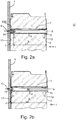
- Figures 1 , and 2b show a fastening system for fastening sandwich-structured composite panels 1 to a support structure 2.
- the sandwich-structured composite panel 1 may be a façade cladding panel element, or a partition wall panel element, or a ceiling panel element.
- the fastening system comprises a sandwich-structured composite panel 1 comprising a first face skin 3 of sheet metal, a second face skin 4 of sheet metal, and a core 5 made of thermally insulating material arranged between the first face skin 3 and the second face skin 4.
- the core 5 may comprise foamed polyurethane or foamed polyisocyanurate (PIR) or mineral wool.
- the core 5 may be a board of foamed polyurethane or foamed polyisocyanurate (PIR) or mineral wool or a combination thereof.
- the first face skin 3 and the second face skin 4 are attached to the core 5.
- the fastening system further comprises a fastener 6 for fastening the sandwich-structured composite panel 1 to the support structure 2.
- the fastener 6 may be a a metal screw, a wood screw, a self-drilling screw, a self-tapping screw or a concrete fastener.
- the type of the fastener is chosen suitably depending on the structure and material of the support structure 2 (e.g. metal, wood or concrete).
- the fastening system comprises an installation hole 7 formed through the first face skin 3 and the core 5.
- An elongated sleeve 8 is insertable into the installation hole 7.
- the sleeve 8 is made of non-metallic, galvanically isolating and thermally insulating material.
- Preferably the sleeve is made of plastic-based material.
- the sleeve 8 comprises a tubular portion 9 having a first end 10 and a second end 11.
- a hollow interior 12 is defined by a side wall 13 of the tubular portion 9.
- a bottom wall 14 is at a second end 11.
- a collar flange 15 encircles an open mouth 16 at the first end 10.
- the sleeve 8 has a length L1 extending in the installation hole 7 from the first face skin 3 towards the second face skin 4 to a shorter distance than the thickness of the panel 1.
- the sleeve 8 forms an installation guide for the fastener 6 which is insertable into the interior 12 of the sleeve 8 and fastenable through the bottom wall 14 of the sleeve 8.
- the collar flange 15 abuts against an outer surface 18 of the first face skin 3 and the fastener 6 being fastened to the support structure 2 pressing the second face skin 4 against the support structure 2.
- there is a member 100 of resilient material installed between the bottom wall 14 of the sleeve and the inner surface 17 of the second face skin 4.
- the sleeve 8 has a length L2 corresponding to a combined thickness of the core 5 and the first face skin 3.
- the sleeve 8 forms an installation guide for the fastener 6 which is insertable into the interior 12 and fastenable through the bottom wall 14.
- the bottom wall 14 abuts against an inner surface 17 of the second face skin 4 and the collar flange 15 abuts against an outer surface 18 of the first face skin 3.
- the fastener 6, in this example self-drilling screw 6 is screwed through the second face skin 4 to the support structure 2, the screwhead of the screw 6 becomes pressed against the wall bottom 14, and the wall bottom 14 presses the second face skin 4 firmly against the support structure 2.
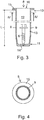
- FIG 3 shows that in one embodiment the sleeve 8 is equipped with a fastener 6 which is pre-installed in the interior 12 of the sleeve 8, so that the fastener 6 is readily fastenable after the sleeve 8 has been installed into the installation hole 7 of the panel 1 at the building site.
- the sleeve 8 may be either factory installed in the installation hole 7, or the sleeve 8 can be installed therein at the building site.
- the installation holes 7 are factory made in the panel 1.
- the diameter of the installation hole 7 is of the order 20 ... 25 mm, for example.
- the outer diameter of the tubular portion 9 of the sleeve 8 is 20 ... 25 mm, for example.
- the first face skin and the second face skin may be made of aluminum or steel.
- the thickness of the first face skin and the second face skin is less than 1 mm, preferably 0,5 ... 0,6 mm.
- the thickness of the panel 1 may be e.g. 100 ... 230 mm.
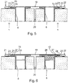
- the fastening system may comprise a flashing 19 to cover a seam 20 between two sandwich-structured composite panels 1 which are adjacently next to each other.
- the flashing 19 has two parallel longitudinal edges 21, 22 both of the edges having an overbent portion 23 forming a U-shaped groove 24.
- the flashing 19 is attached by the aid of the collar flanges 15 of the sleeves 8.
- the collar flange 15 comprises a stepped flange portion 25 insertable to said U-shaped groove 24 for attaching the flashing 19.
- the fastening system comprises a cap 26 attachable to the mouth 16 of the sleeve 8.
- the cap 26 has a cap flange portion 27 extending over and beyond the periphery of the collar flange 15 of the sleeve 8.
- the flashing 19 is attached by the aid of the cap flange portions 27 which are insertable to the U-shaped groove 24 for attaching the flashing 19.
- Figure 6 on the left-hand side, shows an example wherein the cap 16 may be attached onto the mouth 16 of the sleeve 8 by an annular snap-fit joint.
- Figure 6 on the right-hand side shows another example wherein the cap 16 may be attached onto the mouth 16 of the sleeve 8 by a threaded joint.
- the fastening system has at least the following benefits:
Landscapes
- Engineering & Computer Science (AREA)
- Architecture (AREA)
- Civil Engineering (AREA)
- Structural Engineering (AREA)
- Finishing Walls (AREA)
Claims (13)
- Système de fixation pour fixer des panneaux composites à structure sandwich (1) à une structure de support (2), le système de fixation comprenant- un panneau composite à structure sandwich (1) comprenant une première peau de parement (3) en tôle, une deuxième peau de parement (4) en tôle et une âme (5) en matériau thermiquement isolant disposée entre la première peau de parement et la deuxième peau de parement, les première et deuxième peaux de parement étant assemblées à l'âme, et- un élément de fixation (6) pour fixer le panneau composite à structure sandwich (1) à la structure de support (2), le système de fixation comprenant un trou d'installation (7) formé à travers la première peau de parement (3) et l'âme (5), et un manchon allongé (8) apte à être inséré dans le trou d'installation (7), le manchon (8) étant en matériau non métallique, galvaniquement isolant et thermiquement isolant, le manchon (8) comprenant une partie tubulaire (9) ayant une première extrémité (10), une deuxième extrémité (11), un intérieur creux (12) défini par une paroi latérale (13) de la partie tubulaire (9), une paroi inférieure (14) au niveau d'une deuxième extrémité (11) et une collerette (15) encerclant une embouchure ouverte (16) au niveau de la première extrémité (10), le manchon (8) ayant une longueur (L1, L2) s'étendant dans le trou d'installation (7) depuis la première peau de parement (3) vers la deuxième peau de parement (4), selon lequel le manchon (8) forme un guide d'installation pour l'élément de fixation (6) qui est apte à être inséré dans l'intérieur (12) et apte à être fixé à travers la paroi inférieure (14), selon lequel, lorsque le manchon (8) est dans le trou d'installation (7), la collerette (15) vient en butée contre une surface externe (18) de la première peau de parement (3) et l'élément de fixation (6) étant fixé à la structure de support (2) presse la deuxième peau de parement (4) contre la structure de support (2), caractérisé en ce que le manchon (8) a une longueur (L) correspondant à une épaisseur combinée de l'âme (5) et de la première peau de parement (3), selon lequel lorsque le manchon (8) est dans le trou d'installation (7), la paroi inférieure (14) vient en butée contre une surface interne (17) de la deuxième peau de parement (4).
- Système de fixation selon la revendication 1, caractérisé en ce que l'élément de fixation (6) est au moins l'un parmi une vis à métaux, une vis à bois, une vis autoforeuse, une vis autotaraudeuse, un élément de fixation béton.
- Système de fixation selon l'une quelconque des revendications 1 à 2, caractérisé en ce que le manchon (8) est en matériau à base de plastique.
- Système de fixation selon l'une quelconque des revendications 1 à 3, caractérisé en ce que l'âme (5) comprend de la mousse de polyuréthane.
- Système de fixation selon l'une quelconque des revendications 1 à 4, caractérisé en ce que l'âme (5) comprend du polyisocyanurate (PIR).
- Système de fixation selon l'une quelconque des revendications 1 à 5, caractérisé en ce que l'âme (5) comprend de la laine minérale.
- Système de fixation selon l'une quelconque des revendications 1 à 6, caractérisé en ce que l'âme (5) est une plaque de mousse de polyuréthane ou une plaque de polyisocyanurate ou une plaque de laine minérale ou toute combinaison de ceux-ci.
- Système de fixation selon l'une quelconque des revendications 1 à 7, caractérisé en ce que le panneau composite à structure sandwich (1) est un élément de panneau de revêtement de façade, ou un élément de panneau de paroi de séparation, ou un élément de panneau de plafond.
- Système de fixation selon l'une quelconque des revendications 1 à 8, caractérisé en ce que le système de fixation comprend une bande d'étanchéité (19) pour recouvrir un joint (20) entre deux panneaux composites à structure sandwich (1) qui sont adjacents l'un de l'autre, la bande d'étanchéité (19) ayant deux bords longitudinaux parallèles (21, 22), les deux bords ayant une partie repliée (23) formant une rainure en forme de U (24).
- Système de fixation selon la revendication 9, caractérisé en ce que la bande d'étanchéité (19) est assemblée à l'aide des collerettes (15) des manchons (8).
- Système de fixation selon la revendication 10, caractérisé en ce que la collerette (15) comprend une partie d'épaulement (25) apte à être insérée dans ladite rainure en forme de U (24) pour assembler la bande d'étanchéité (19).
- Système de fixation selon la revendication 9, caractérisé en ce que le système de fixation comprend un capuchon (26) apte à être assemblé à l'embouchure (16) du manchon (8) ; le capuchon (26) ayant une partie de bride de capuchon (27) s'étendant sur et au-delà de la périphérie de la collerette (15) du manchon (8) ; et en ce que la bande d'étanchéité (19) est assemblée à l'aide des parties de bride de capuchon (27), les parties de bride de capuchon pouvant être insérées dans ladite rainure en forme de U (24) pour assembler la bande d'étanchéité (19).
- Utilisation du système de fixation selon l'une quelconque des revendications 1 à 12 pour fixer des éléments de panneau de revêtement de façade ou des éléments de panneau de paroi de séparation ou des éléments de panneau de plafond, de type composite à structure sandwich, à une structure de support.
Priority Applications (3)
| Application Number | Priority Date | Filing Date | Title |
|---|---|---|---|
| PL19179936T PL3751069T3 (pl) | 2019-06-13 | 2019-06-13 | System mocowania do zamocowania paneli kompozytowych o strukturze warstwowej do konstrukcji podporowej |
| LTEP19179936.0T LT3751069T (lt) | 2019-06-13 | 2019-06-13 | Tvirtinimo sistema, skirta daugiasluoksnės struktūros kompozitinėms plokštėms prie laikančiosios konstrukcijos tvirtinti |
| EP19179936.0A EP3751069B1 (fr) | 2019-06-13 | 2019-06-13 | Système de fixation pour fixer des panneaux composites à structure en sandwich à une structure de support |
Applications Claiming Priority (1)
| Application Number | Priority Date | Filing Date | Title |
|---|---|---|---|
| EP19179936.0A EP3751069B1 (fr) | 2019-06-13 | 2019-06-13 | Système de fixation pour fixer des panneaux composites à structure en sandwich à une structure de support |
Publications (2)
| Publication Number | Publication Date |
|---|---|
| EP3751069A1 EP3751069A1 (fr) | 2020-12-16 |
| EP3751069B1 true EP3751069B1 (fr) | 2021-11-10 |
Family
ID=67180490
Family Applications (1)
| Application Number | Title | Priority Date | Filing Date |
|---|---|---|---|
| EP19179936.0A Active EP3751069B1 (fr) | 2019-06-13 | 2019-06-13 | Système de fixation pour fixer des panneaux composites à structure en sandwich à une structure de support |
Country Status (3)
| Country | Link |
|---|---|
| EP (1) | EP3751069B1 (fr) |
| LT (1) | LT3751069T (fr) |
| PL (1) | PL3751069T3 (fr) |
Citations (1)
| Publication number | Priority date | Publication date | Assignee | Title |
|---|---|---|---|---|
| US4653246A (en) * | 1984-01-05 | 1987-03-31 | Hepler Jacque P | Insulation board for attachment to walls |
Family Cites Families (4)
| Publication number | Priority date | Publication date | Assignee | Title |
|---|---|---|---|---|
| IT1028941B (it) * | 1975-04-11 | 1979-02-10 | Scanalpina Spa | Pannelli isolanti e procedimento di costruzione e montaggio degli stessi |
| DE3931833A1 (de) * | 1989-09-23 | 1991-04-04 | Hilti Ag | Befestigungselement zum befestigen von isolationsplatten |
| ES1065136Y (es) * | 2007-03-28 | 2007-09-16 | Curbiperfil S A | Dispositivo de cerramiento decorativo plano para cubiertas y fachadas de grandes longitudes |
| PL68194Y1 (pl) * | 2008-06-26 | 2016-01-29 | Żebrowski Tomasz Swal | Element do mocowania płyt izolacyjnych |
-
2019
- 2019-06-13 LT LTEP19179936.0T patent/LT3751069T/lt unknown
- 2019-06-13 PL PL19179936T patent/PL3751069T3/pl unknown
- 2019-06-13 EP EP19179936.0A patent/EP3751069B1/fr active Active
Patent Citations (1)
| Publication number | Priority date | Publication date | Assignee | Title |
|---|---|---|---|---|
| US4653246A (en) * | 1984-01-05 | 1987-03-31 | Hepler Jacque P | Insulation board for attachment to walls |
Also Published As
| Publication number | Publication date |
|---|---|
| PL3751069T3 (pl) | 2022-03-07 |
| EP3751069A1 (fr) | 2020-12-16 |
| LT3751069T (lt) | 2021-12-27 |
Similar Documents
| Publication | Publication Date | Title |
|---|---|---|
| US6131360A (en) | Plastic anchor system for use with masonry over steel stud back-up walls | |
| CN108678294B (zh) | 一种装配式金属屋面屋脊节点及其安装方法 | |
| US11035121B2 (en) | Thermal and acoustic insulating and sealing system for a safing slot in a curtain wall | |
| US3302350A (en) | Molding construction | |
| US9869086B2 (en) | Thermal insulating and sealing means for a safing slot in a curtain wall | |
| EP3458653B1 (fr) | Construction de bâtiment ayant un mur-rideau comprenant un système d'isolation thermique et acoustique et d'étanchéité d'une fente de sécurité | |
| EP1179645B2 (fr) | Mur d'une façade de bâtiment | |
| US5694724A (en) | Vent pipe cover | |
| CN109139657B (zh) | 带有多线的头部下方螺纹的螺钉和为此的固定系统 | |
| US7107732B2 (en) | Purlin clip for an insulated ceiling of a metal building | |
| KR20150094366A (ko) | 외단열 시스템과 이를 이용한 외벽 설치방법 | |
| EP3751069B1 (fr) | Système de fixation pour fixer des panneaux composites à structure en sandwich à une structure de support | |
| GB2187408A (en) | Self-tapping screw | |
| EP2759656A1 (fr) | Panneau protecteur d'isolation à la chaleur extérieure | |
| ATE215158T1 (de) | Isolationselement für klemmende befestigung zwischen dachsparren oder balken anderer holzkonstruktionen | |
| JP6108578B2 (ja) | 建築用パネルの接続構造 | |
| JP2016148243A (ja) | 建築用パネルの接続構造 | |
| KR20160089650A (ko) | 건축용 외장 패널 시스템 및 이의 설치 방법 | |
| EP2703574A2 (fr) | Élément isolant | |
| US20250327309A1 (en) | Isolator pad for a bracket for a façade cladding system | |
| RU2533463C1 (ru) | Способ соединения фальцевой кровли со стропилами и утеплителем | |
| KR20060026237A (ko) | 시공성 및 내화성능이 우수한 강재기둥 | |
| US5060429A (en) | Ceiling-wall attachment | |
| JP6599141B2 (ja) | 圧潰防止具及び複合パネル | |
| RU2123564C1 (ru) | Ограждающая конструкция |
Legal Events
| Date | Code | Title | Description |
|---|---|---|---|
| PUAI | Public reference made under article 153(3) epc to a published international application that has entered the european phase |
Free format text: ORIGINAL CODE: 0009012 |
|
| STAA | Information on the status of an ep patent application or granted ep patent |
Free format text: STATUS: THE APPLICATION HAS BEEN PUBLISHED |
|
| AK | Designated contracting states |
Kind code of ref document: A1 Designated state(s): AL AT BE BG CH CY CZ DE DK EE ES FI FR GB GR HR HU IE IS IT LI LT LU LV MC MK MT NL NO PL PT RO RS SE SI SK SM TR |
|
| AX | Request for extension of the european patent |
Extension state: BA ME |
|
| STAA | Information on the status of an ep patent application or granted ep patent |
Free format text: STATUS: REQUEST FOR EXAMINATION WAS MADE |
|
| 17P | Request for examination filed |
Effective date: 20210125 |
|
| RBV | Designated contracting states (corrected) |
Designated state(s): AL AT BE BG CH CY CZ DE DK EE ES FI FR GB GR HR HU IE IS IT LI LT LU LV MC MK MT NL NO PL PT RO RS SE SI SK SM TR |
|
| RIN1 | Information on inventor provided before grant (corrected) |
Inventor name: KESTI, JYRKI Inventor name: HONKAKOSKI, ERKKI |
|
| GRAP | Despatch of communication of intention to grant a patent |
Free format text: ORIGINAL CODE: EPIDOSNIGR1 |
|
| STAA | Information on the status of an ep patent application or granted ep patent |
Free format text: STATUS: GRANT OF PATENT IS INTENDED |
|
| INTG | Intention to grant announced |
Effective date: 20210705 |
|
| GRAS | Grant fee paid |
Free format text: ORIGINAL CODE: EPIDOSNIGR3 |
|
| GRAA | (expected) grant |
Free format text: ORIGINAL CODE: 0009210 |
|
| STAA | Information on the status of an ep patent application or granted ep patent |
Free format text: STATUS: THE PATENT HAS BEEN GRANTED |
|
| AK | Designated contracting states |
Kind code of ref document: B1 Designated state(s): AL AT BE BG CH CY CZ DE DK EE ES FI FR GB GR HR HU IE IS IT LI LT LU LV MC MK MT NL NO PL PT RO RS SE SI SK SM TR |
|
| REG | Reference to a national code |
Ref country code: GB Ref legal event code: FG4D |
|
| REG | Reference to a national code |
Ref country code: AT Ref legal event code: REF Ref document number: 1446230 Country of ref document: AT Kind code of ref document: T Effective date: 20211115 Ref country code: CH Ref legal event code: EP |
|
| REG | Reference to a national code |
Ref country code: DE Ref legal event code: R096 Ref document number: 602019009094 Country of ref document: DE |
|
| REG | Reference to a national code |
Ref country code: SE Ref legal event code: TRGR |
|
| REG | Reference to a national code |
Ref country code: IE Ref legal event code: FG4D |
|
| REG | Reference to a national code |
Ref country code: FI Ref legal event code: FGE |
|
| REG | Reference to a national code |
Ref country code: NO Ref legal event code: T2 Effective date: 20211110 |
|
| REG | Reference to a national code |
Ref country code: EE Ref legal event code: FG4A Ref document number: E021933 Country of ref document: EE Effective date: 20220128 |
|
| REG | Reference to a national code |
Ref country code: NL Ref legal event code: MP Effective date: 20211110 |
|
| REG | Reference to a national code |
Ref country code: AT Ref legal event code: MK05 Ref document number: 1446230 Country of ref document: AT Kind code of ref document: T Effective date: 20211110 |
|
| PG25 | Lapsed in a contracting state [announced via postgrant information from national office to epo] |
Ref country code: RS Free format text: LAPSE BECAUSE OF FAILURE TO SUBMIT A TRANSLATION OF THE DESCRIPTION OR TO PAY THE FEE WITHIN THE PRESCRIBED TIME-LIMIT Effective date: 20211110 Ref country code: BG Free format text: LAPSE BECAUSE OF FAILURE TO SUBMIT A TRANSLATION OF THE DESCRIPTION OR TO PAY THE FEE WITHIN THE PRESCRIBED TIME-LIMIT Effective date: 20220210 Ref country code: AT Free format text: LAPSE BECAUSE OF FAILURE TO SUBMIT A TRANSLATION OF THE DESCRIPTION OR TO PAY THE FEE WITHIN THE PRESCRIBED TIME-LIMIT Effective date: 20211110 |
|
| PG25 | Lapsed in a contracting state [announced via postgrant information from national office to epo] |
Ref country code: IS Free format text: LAPSE BECAUSE OF FAILURE TO SUBMIT A TRANSLATION OF THE DESCRIPTION OR TO PAY THE FEE WITHIN THE PRESCRIBED TIME-LIMIT Effective date: 20220310 Ref country code: PT Free format text: LAPSE BECAUSE OF FAILURE TO SUBMIT A TRANSLATION OF THE DESCRIPTION OR TO PAY THE FEE WITHIN THE PRESCRIBED TIME-LIMIT Effective date: 20220310 Ref country code: NL Free format text: LAPSE BECAUSE OF FAILURE TO SUBMIT A TRANSLATION OF THE DESCRIPTION OR TO PAY THE FEE WITHIN THE PRESCRIBED TIME-LIMIT Effective date: 20211110 Ref country code: HR Free format text: LAPSE BECAUSE OF FAILURE TO SUBMIT A TRANSLATION OF THE DESCRIPTION OR TO PAY THE FEE WITHIN THE PRESCRIBED TIME-LIMIT Effective date: 20211110 Ref country code: GR Free format text: LAPSE BECAUSE OF FAILURE TO SUBMIT A TRANSLATION OF THE DESCRIPTION OR TO PAY THE FEE WITHIN THE PRESCRIBED TIME-LIMIT Effective date: 20220211 |
|
| PG25 | Lapsed in a contracting state [announced via postgrant information from national office to epo] |
Ref country code: SM Free format text: LAPSE BECAUSE OF FAILURE TO SUBMIT A TRANSLATION OF THE DESCRIPTION OR TO PAY THE FEE WITHIN THE PRESCRIBED TIME-LIMIT Effective date: 20211110 Ref country code: SK Free format text: LAPSE BECAUSE OF FAILURE TO SUBMIT A TRANSLATION OF THE DESCRIPTION OR TO PAY THE FEE WITHIN THE PRESCRIBED TIME-LIMIT Effective date: 20211110 Ref country code: RO Free format text: LAPSE BECAUSE OF FAILURE TO SUBMIT A TRANSLATION OF THE DESCRIPTION OR TO PAY THE FEE WITHIN THE PRESCRIBED TIME-LIMIT Effective date: 20211110 Ref country code: ES Free format text: LAPSE BECAUSE OF FAILURE TO SUBMIT A TRANSLATION OF THE DESCRIPTION OR TO PAY THE FEE WITHIN THE PRESCRIBED TIME-LIMIT Effective date: 20211110 Ref country code: DK Free format text: LAPSE BECAUSE OF FAILURE TO SUBMIT A TRANSLATION OF THE DESCRIPTION OR TO PAY THE FEE WITHIN THE PRESCRIBED TIME-LIMIT Effective date: 20211110 Ref country code: CZ Free format text: LAPSE BECAUSE OF FAILURE TO SUBMIT A TRANSLATION OF THE DESCRIPTION OR TO PAY THE FEE WITHIN THE PRESCRIBED TIME-LIMIT Effective date: 20211110 |
|
| REG | Reference to a national code |
Ref country code: DE Ref legal event code: R097 Ref document number: 602019009094 Country of ref document: DE |
|
| PLBE | No opposition filed within time limit |
Free format text: ORIGINAL CODE: 0009261 |
|
| STAA | Information on the status of an ep patent application or granted ep patent |
Free format text: STATUS: NO OPPOSITION FILED WITHIN TIME LIMIT |
|
| 26N | No opposition filed |
Effective date: 20220811 |
|
| PG25 | Lapsed in a contracting state [announced via postgrant information from national office to epo] |
Ref country code: AL Free format text: LAPSE BECAUSE OF FAILURE TO SUBMIT A TRANSLATION OF THE DESCRIPTION OR TO PAY THE FEE WITHIN THE PRESCRIBED TIME-LIMIT Effective date: 20211110 |
|
| PG25 | Lapsed in a contracting state [announced via postgrant information from national office to epo] |
Ref country code: SI Free format text: LAPSE BECAUSE OF FAILURE TO SUBMIT A TRANSLATION OF THE DESCRIPTION OR TO PAY THE FEE WITHIN THE PRESCRIBED TIME-LIMIT Effective date: 20211110 |
|
| PG25 | Lapsed in a contracting state [announced via postgrant information from national office to epo] |
Ref country code: MC Free format text: LAPSE BECAUSE OF FAILURE TO SUBMIT A TRANSLATION OF THE DESCRIPTION OR TO PAY THE FEE WITHIN THE PRESCRIBED TIME-LIMIT Effective date: 20211110 |
|
| REG | Reference to a national code |
Ref country code: CH Ref legal event code: PL |
|
| REG | Reference to a national code |
Ref country code: BE Ref legal event code: MM Effective date: 20220630 |
|
| PG25 | Lapsed in a contracting state [announced via postgrant information from national office to epo] |
Ref country code: LU Free format text: LAPSE BECAUSE OF NON-PAYMENT OF DUE FEES Effective date: 20220613 Ref country code: LI Free format text: LAPSE BECAUSE OF NON-PAYMENT OF DUE FEES Effective date: 20220630 Ref country code: IE Free format text: LAPSE BECAUSE OF NON-PAYMENT OF DUE FEES Effective date: 20220613 Ref country code: FR Free format text: LAPSE BECAUSE OF NON-PAYMENT OF DUE FEES Effective date: 20220630 Ref country code: CH Free format text: LAPSE BECAUSE OF NON-PAYMENT OF DUE FEES Effective date: 20220630 |
|
| PG25 | Lapsed in a contracting state [announced via postgrant information from national office to epo] |
Ref country code: IT Free format text: LAPSE BECAUSE OF FAILURE TO SUBMIT A TRANSLATION OF THE DESCRIPTION OR TO PAY THE FEE WITHIN THE PRESCRIBED TIME-LIMIT Effective date: 20211110 Ref country code: BE Free format text: LAPSE BECAUSE OF NON-PAYMENT OF DUE FEES Effective date: 20220630 |
|
| GBPC | Gb: european patent ceased through non-payment of renewal fee |
Effective date: 20230613 |
|
| PG25 | Lapsed in a contracting state [announced via postgrant information from national office to epo] |
Ref country code: MK Free format text: LAPSE BECAUSE OF FAILURE TO SUBMIT A TRANSLATION OF THE DESCRIPTION OR TO PAY THE FEE WITHIN THE PRESCRIBED TIME-LIMIT Effective date: 20211110 Ref country code: CY Free format text: LAPSE BECAUSE OF FAILURE TO SUBMIT A TRANSLATION OF THE DESCRIPTION OR TO PAY THE FEE WITHIN THE PRESCRIBED TIME-LIMIT Effective date: 20211110 Ref country code: GB Free format text: LAPSE BECAUSE OF NON-PAYMENT OF DUE FEES Effective date: 20230613 |
|
| PG25 | Lapsed in a contracting state [announced via postgrant information from national office to epo] |
Ref country code: HU Free format text: LAPSE BECAUSE OF FAILURE TO SUBMIT A TRANSLATION OF THE DESCRIPTION OR TO PAY THE FEE WITHIN THE PRESCRIBED TIME-LIMIT; INVALID AB INITIO Effective date: 20190613 |
|
| PG25 | Lapsed in a contracting state [announced via postgrant information from national office to epo] |
Ref country code: MT Free format text: LAPSE BECAUSE OF FAILURE TO SUBMIT A TRANSLATION OF THE DESCRIPTION OR TO PAY THE FEE WITHIN THE PRESCRIBED TIME-LIMIT Effective date: 20211110 |
|
| PGFP | Annual fee paid to national office [announced via postgrant information from national office to epo] |
Ref country code: FI Payment date: 20250616 Year of fee payment: 7 |
|
| PGFP | Annual fee paid to national office [announced via postgrant information from national office to epo] |
Ref country code: DE Payment date: 20250618 Year of fee payment: 7 Ref country code: PL Payment date: 20250529 Year of fee payment: 7 |
|
| PGFP | Annual fee paid to national office [announced via postgrant information from national office to epo] |
Ref country code: LT Payment date: 20250530 Year of fee payment: 7 |
|
| PGFP | Annual fee paid to national office [announced via postgrant information from national office to epo] |
Ref country code: NO Payment date: 20250618 Year of fee payment: 7 |
|
| PGFP | Annual fee paid to national office [announced via postgrant information from national office to epo] |
Ref country code: LV Payment date: 20250618 Year of fee payment: 7 |
|
| PGFP | Annual fee paid to national office [announced via postgrant information from national office to epo] |
Ref country code: EE Payment date: 20250629 Year of fee payment: 7 |
|
| PGFP | Annual fee paid to national office [announced via postgrant information from national office to epo] |
Ref country code: SE Payment date: 20250618 Year of fee payment: 7 |
|
| PG25 | Lapsed in a contracting state [announced via postgrant information from national office to epo] |
Ref country code: TR Free format text: LAPSE BECAUSE OF FAILURE TO SUBMIT A TRANSLATION OF THE DESCRIPTION OR TO PAY THE FEE WITHIN THE PRESCRIBED TIME-LIMIT Effective date: 20211110 |