EP3751069B1 - Fastening system for fastening sandwich-structured composite panels to a support structure - Google Patents
Fastening system for fastening sandwich-structured composite panels to a support structure Download PDFInfo
- Publication number
- EP3751069B1 EP3751069B1 EP19179936.0A EP19179936A EP3751069B1 EP 3751069 B1 EP3751069 B1 EP 3751069B1 EP 19179936 A EP19179936 A EP 19179936A EP 3751069 B1 EP3751069 B1 EP 3751069B1
- Authority
- EP
- European Patent Office
- Prior art keywords
- fastening system
- sleeve
- face skin
- sandwich
- fastening
- Prior art date
- Legal status (The legal status is an assumption and is not a legal conclusion. Google has not performed a legal analysis and makes no representation as to the accuracy of the status listed.)
- Active
Links
Images

Classifications
-
- E—FIXED CONSTRUCTIONS
- E04—BUILDING
- E04F—FINISHING WORK ON BUILDINGS, e.g. STAIRS, FLOORS
- E04F13/00—Coverings or linings, e.g. for walls or ceilings
- E04F13/07—Coverings or linings, e.g. for walls or ceilings composed of covering or lining elements; Sub-structures therefor; Fastening means therefor
- E04F13/08—Coverings or linings, e.g. for walls or ceilings composed of covering or lining elements; Sub-structures therefor; Fastening means therefor composed of a plurality of similar covering or lining elements
- E04F13/0866—Coverings or linings, e.g. for walls or ceilings composed of covering or lining elements; Sub-structures therefor; Fastening means therefor composed of a plurality of similar covering or lining elements composed of several layers, e.g. sandwich panels or layered panels
-
- E—FIXED CONSTRUCTIONS
- E04—BUILDING
- E04F—FINISHING WORK ON BUILDINGS, e.g. STAIRS, FLOORS
- E04F13/00—Coverings or linings, e.g. for walls or ceilings
- E04F13/07—Coverings or linings, e.g. for walls or ceilings composed of covering or lining elements; Sub-structures therefor; Fastening means therefor
- E04F13/08—Coverings or linings, e.g. for walls or ceilings composed of covering or lining elements; Sub-structures therefor; Fastening means therefor composed of a plurality of similar covering or lining elements
- E04F13/0801—Separate fastening elements
- E04F13/0832—Separate fastening elements without load-supporting elongated furring elements between wall and covering elements
- E04F13/0833—Separate fastening elements without load-supporting elongated furring elements between wall and covering elements not adjustable
- E04F13/0846—Separate fastening elements without load-supporting elongated furring elements between wall and covering elements not adjustable the fastening elements engaging holes or grooves in the side faces of the covering elements
-
- E—FIXED CONSTRUCTIONS
- E04—BUILDING
- E04F—FINISHING WORK ON BUILDINGS, e.g. STAIRS, FLOORS
- E04F13/00—Coverings or linings, e.g. for walls or ceilings
- E04F13/07—Coverings or linings, e.g. for walls or ceilings composed of covering or lining elements; Sub-structures therefor; Fastening means therefor
- E04F13/08—Coverings or linings, e.g. for walls or ceilings composed of covering or lining elements; Sub-structures therefor; Fastening means therefor composed of a plurality of similar covering or lining elements
- E04F13/0875—Coverings or linings, e.g. for walls or ceilings composed of covering or lining elements; Sub-structures therefor; Fastening means therefor composed of a plurality of similar covering or lining elements having a basic insulating layer and at least one covering layer
-
- E—FIXED CONSTRUCTIONS
- E04—BUILDING
- E04F—FINISHING WORK ON BUILDINGS, e.g. STAIRS, FLOORS
- E04F13/00—Coverings or linings, e.g. for walls or ceilings
- E04F13/07—Coverings or linings, e.g. for walls or ceilings composed of covering or lining elements; Sub-structures therefor; Fastening means therefor
- E04F13/08—Coverings or linings, e.g. for walls or ceilings composed of covering or lining elements; Sub-structures therefor; Fastening means therefor composed of a plurality of similar covering or lining elements
- E04F13/12—Coverings or linings, e.g. for walls or ceilings composed of covering or lining elements; Sub-structures therefor; Fastening means therefor composed of a plurality of similar covering or lining elements of metal or with an outer layer of metal or enameled metal
Definitions
- the present invention relates to a fastening system for fastening sandwich-structured composite panels to a support structure.
- a fastening system for fastening sandwich-structured composite panels to a support structure.
- Sandwich-structured composite panels are fastened to the support structure by screws.
- thick sandwich-structured composite panels are used as thermally insulated façade cladding panel elements, partition wall panel elements or ceiling panel elements.
- the thickness of the panel may be e.g. 230 mm.
- the length of the screw is usually about 30...40mm longer than the thickness of the panel. Long screws are needed for fastening the panels to the support structure since the screw extends through and beyond the whole thickness of the panel, and when tightened, the screwhead abuts against the outer surface of the panel. Long screws have a drawback that they are costly.
- the objective of the invention is to alleviate the disadvantages mentioned above.
- the present invention provides a fastening system for fastening sandwich-structured composite panels to a support structure.
- the fastening system comprises a sandwich-structured composite panel comprising a first face skin of sheet metal, a second face skin of sheet metal, and a core made of thermally insulating material arranged between the first face skin and the second face skin. The first and second face skins are attached to the core.
- the fastening system further comprises a fastener for fastening the sandwich-structured composite panel to the support structure.
- the fastening system comprises an installation hole formed through the first face skin and the core, and an elongated sleeve insertable into the installation hole.
- the sleeve is made of non-metallic, galvanically isolating and thermally insulating material.
- the sleeve comprises a tubular portion having a first end and a second end.
- the sleeve has a hollow interior defined by a side wall of the tubular portion.
- the sleeve further comprises a bottom wall at a second end and a collar flange encircling an open mouth at the first end.
- the sleeve has a length extending in the installation hole from the first face skin towards the second face skin.
- the sleeve forms an installation guide for the fastener which is insertable into the interior and fastenable through the bottom wall. When the sleeve is in the installation hole, the collar flange abuts against an outer surface of the first face skin. The fastener being fastened to the support structure presses the second face skin against the support structure.
- the technical effect of the invention is that the fastening system enables easy and fast panel installation with short and cheap screws.
- the sandwich-structured composite panel can be provided by factory-made installation holes.
- the sleeve can be installed into the installation hole either in the factory or on the site.
- a short fastener is attached through a pre-manufactured hole in the bottom of the sleeve into the support structure.
- the pre-manufactured hole may be drilled or punched, for example.
- the sleeve is equipped with a collar flange round the outer face skin in order to enable wind suction load transfer to the support structure. Because the length of the sleeve matches exactly with the panel thickness, there is no risk for failures in the outer face skin during fastening.
- the sleeve has a length corresponding to a combined thickness of the core and the first face skin, whereby when the sleeve is in the installation hole, the bottom wall abuts against an inner surface of the second face skin.
- the fastener is at least one of a metal screw, a wood screw, a self-drilling screw, a self-tapping screw, a concrete fastener.
- the sleeve is made of plastic-based material.
- the core comprises foamed polyurethane.
- the core comprises polyisocyanurate (PIR).
- the core comprises mineral wool.
- the core may be a board of foamed polyurethane, polyisocyanurate or mineral wool or any combination thereof.
- the sandwich-structured composite panel is a façade cladding panel element, or a partition wall panel element, or a ceiling panel element.
- the fastening system comprises a flashing to cover a seam between two sandwich-structured composite panels which are adjacently next to each other, the flashing having two parallel longitudinal edges both of the edges having an overbent portion forming a U-shaped groove.
- the flashing is attached by the aid of the collar flanges of the sleeves.
- the collar flange comprises a stepped flange portion insertable to said U-shaped groove for attaching the flashing.
- the fastening system comprises a cap attachable to the mouth of the sleeve.
- the cap has a cap flange portion extending over and beyond the periphery of the collar flange of the sleeve.
- the flashing is attached by the aid of the cap flange portions, the cap flange portions being insertable to said U-shaped groove for attaching the flashing.
- the present invention provides use of the fastening system according to the first aspect for fastening of sandwich-structured composite façade cladding panel elements or partition wall panel elements or ceiling panel elements to a support structure
- Figures 1 , and 2b show a fastening system for fastening sandwich-structured composite panels 1 to a support structure 2.
- the sandwich-structured composite panel 1 may be a façade cladding panel element, or a partition wall panel element, or a ceiling panel element.
- the fastening system comprises a sandwich-structured composite panel 1 comprising a first face skin 3 of sheet metal, a second face skin 4 of sheet metal, and a core 5 made of thermally insulating material arranged between the first face skin 3 and the second face skin 4.
- the core 5 may comprise foamed polyurethane or foamed polyisocyanurate (PIR) or mineral wool.
- the core 5 may be a board of foamed polyurethane or foamed polyisocyanurate (PIR) or mineral wool or a combination thereof.
- the first face skin 3 and the second face skin 4 are attached to the core 5.
- the fastening system further comprises a fastener 6 for fastening the sandwich-structured composite panel 1 to the support structure 2.
- the fastener 6 may be a a metal screw, a wood screw, a self-drilling screw, a self-tapping screw or a concrete fastener.
- the type of the fastener is chosen suitably depending on the structure and material of the support structure 2 (e.g. metal, wood or concrete).
- the fastening system comprises an installation hole 7 formed through the first face skin 3 and the core 5.
- An elongated sleeve 8 is insertable into the installation hole 7.
- the sleeve 8 is made of non-metallic, galvanically isolating and thermally insulating material.
- Preferably the sleeve is made of plastic-based material.
- the sleeve 8 comprises a tubular portion 9 having a first end 10 and a second end 11.
- a hollow interior 12 is defined by a side wall 13 of the tubular portion 9.
- a bottom wall 14 is at a second end 11.
- a collar flange 15 encircles an open mouth 16 at the first end 10.
- the sleeve 8 has a length L1 extending in the installation hole 7 from the first face skin 3 towards the second face skin 4 to a shorter distance than the thickness of the panel 1.
- the sleeve 8 forms an installation guide for the fastener 6 which is insertable into the interior 12 of the sleeve 8 and fastenable through the bottom wall 14 of the sleeve 8.
- the collar flange 15 abuts against an outer surface 18 of the first face skin 3 and the fastener 6 being fastened to the support structure 2 pressing the second face skin 4 against the support structure 2.
- there is a member 100 of resilient material installed between the bottom wall 14 of the sleeve and the inner surface 17 of the second face skin 4.
- the sleeve 8 has a length L2 corresponding to a combined thickness of the core 5 and the first face skin 3.
- the sleeve 8 forms an installation guide for the fastener 6 which is insertable into the interior 12 and fastenable through the bottom wall 14.
- the bottom wall 14 abuts against an inner surface 17 of the second face skin 4 and the collar flange 15 abuts against an outer surface 18 of the first face skin 3.
- the fastener 6, in this example self-drilling screw 6 is screwed through the second face skin 4 to the support structure 2, the screwhead of the screw 6 becomes pressed against the wall bottom 14, and the wall bottom 14 presses the second face skin 4 firmly against the support structure 2.
- FIG 3 shows that in one embodiment the sleeve 8 is equipped with a fastener 6 which is pre-installed in the interior 12 of the sleeve 8, so that the fastener 6 is readily fastenable after the sleeve 8 has been installed into the installation hole 7 of the panel 1 at the building site.
- the sleeve 8 may be either factory installed in the installation hole 7, or the sleeve 8 can be installed therein at the building site.
- the installation holes 7 are factory made in the panel 1.
- the diameter of the installation hole 7 is of the order 20 ... 25 mm, for example.
- the outer diameter of the tubular portion 9 of the sleeve 8 is 20 ... 25 mm, for example.
- the first face skin and the second face skin may be made of aluminum or steel.
- the thickness of the first face skin and the second face skin is less than 1 mm, preferably 0,5 ... 0,6 mm.
- the thickness of the panel 1 may be e.g. 100 ... 230 mm.
- the fastening system may comprise a flashing 19 to cover a seam 20 between two sandwich-structured composite panels 1 which are adjacently next to each other.
- the flashing 19 has two parallel longitudinal edges 21, 22 both of the edges having an overbent portion 23 forming a U-shaped groove 24.
- the flashing 19 is attached by the aid of the collar flanges 15 of the sleeves 8.
- the collar flange 15 comprises a stepped flange portion 25 insertable to said U-shaped groove 24 for attaching the flashing 19.
- the fastening system comprises a cap 26 attachable to the mouth 16 of the sleeve 8.
- the cap 26 has a cap flange portion 27 extending over and beyond the periphery of the collar flange 15 of the sleeve 8.
- the flashing 19 is attached by the aid of the cap flange portions 27 which are insertable to the U-shaped groove 24 for attaching the flashing 19.
- Figure 6 on the left-hand side, shows an example wherein the cap 16 may be attached onto the mouth 16 of the sleeve 8 by an annular snap-fit joint.
- Figure 6 on the right-hand side shows another example wherein the cap 16 may be attached onto the mouth 16 of the sleeve 8 by a threaded joint.
- the fastening system has at least the following benefits:
Landscapes
- Engineering & Computer Science (AREA)
- Architecture (AREA)
- Civil Engineering (AREA)
- Structural Engineering (AREA)
- Finishing Walls (AREA)
Description
- The present invention relates to a fastening system for fastening sandwich-structured composite panels to a support structure.
- In prior art is known a fastening system for fastening sandwich-structured composite panels to a support structure. Sandwich-structured composite panels are fastened to the support structure by screws. Typically, thick sandwich-structured composite panels are used as thermally insulated façade cladding panel elements, partition wall panel elements or ceiling panel elements. In some examples, the thickness of the panel may be e.g. 230 mm. The length of the screw is usually about 30...40mm longer than the thickness of the panel. Long screws are needed for fastening the panels to the support structure since the screw extends through and beyond the whole thickness of the panel, and when tightened, the screwhead abuts against the outer surface of the panel. Long screws have a drawback that they are costly. Also very often careless screwing with overtightening causes local buckling failures to the outer face skin of the sandwich panel and thus limits re-usability of the panels. Also very broad flashings are needed to hide possible failures. Current system of installing flashings may require several working phases and needs several installation parts and connectors. Re-usability is also limited due to many screw holes from flashing connectors. Long panel screws also cause local thermal bridges to the building envelope. The documents
PL 68194 Y1 US 4653246 A disclose such fastening systems. - The objective of the invention is to alleviate the disadvantages mentioned above.
- According to a first aspect, the present invention provides a fastening system for fastening sandwich-structured composite panels to a support structure. The fastening system comprises a sandwich-structured composite panel comprising a first face skin of sheet metal, a second face skin of sheet metal, and a core made of thermally insulating material arranged between the first face skin and the second face skin. The first and second face skins are attached to the core. The fastening system further comprises a fastener for fastening the sandwich-structured composite panel to the support structure. According to the invention the fastening system comprises an installation hole formed through the first face skin and the core, and an elongated sleeve insertable into the installation hole. The sleeve is made of non-metallic, galvanically isolating and thermally insulating material. The sleeve comprises a tubular portion having a first end and a second end. The sleeve has a hollow interior defined by a side wall of the tubular portion. The sleeve further comprises a bottom wall at a second end and a collar flange encircling an open mouth at the first end. The sleeve has a length extending in the installation hole from the first face skin towards the second face skin. The sleeve forms an installation guide for the fastener which is insertable into the interior and fastenable through the bottom wall. When the sleeve is in the installation hole, the collar flange abuts against an outer surface of the first face skin. The fastener being fastened to the support structure presses the second face skin against the support structure.
- The technical effect of the invention is that the fastening system enables easy and fast panel installation with short and cheap screws. The sandwich-structured composite panel can be provided by factory-made installation holes. The sleeve can be installed into the installation hole either in the factory or on the site. A short fastener is attached through a pre-manufactured hole in the bottom of the sleeve into the support structure. The pre-manufactured hole may be drilled or punched, for example. The sleeve is equipped with a collar flange round the outer face skin in order to enable wind suction load transfer to the support structure. Because the length of the sleeve matches exactly with the panel thickness, there is no risk for failures in the outer face skin during fastening.
- Hence the sleeve has a length corresponding to a combined thickness of the core and the first face skin, whereby when the sleeve is in the installation hole, the bottom wall abuts against an inner surface of the second face skin.
- In an embodiment of the fastening system, the fastener is at least one of a metal screw, a wood screw, a self-drilling screw, a self-tapping screw, a concrete fastener.
- In an embodiment of the fastening system, the sleeve is made of plastic-based material.
- In an embodiment of the fastening system, the core comprises foamed polyurethane.
- In an embodiment of the fastening system, the core comprises polyisocyanurate (PIR).
- In an embodiment of the fastening system, the core comprises mineral wool.
- In an embodiment of the fastening system, the core may be a board of foamed polyurethane, polyisocyanurate or mineral wool or any combination thereof.
- In an embodiment of the fastening system, the sandwich-structured composite panel is a façade cladding panel element, or a partition wall panel element, or a ceiling panel element.
- In an embodiment of the fastening system, the fastening system comprises a flashing to cover a seam between two sandwich-structured composite panels which are adjacently next to each other, the flashing having two parallel longitudinal edges both of the edges having an overbent portion forming a U-shaped groove.
- In an embodiment of the fastening system, the flashing is attached by the aid of the collar flanges of the sleeves.
- In an embodiment of the fastening system, the collar flange comprises a stepped flange portion insertable to said U-shaped groove for attaching the flashing.
- In an embodiment of the fastening system, the fastening system comprises a cap attachable to the mouth of the sleeve. The cap has a cap flange portion extending over and beyond the periphery of the collar flange of the sleeve. The flashing is attached by the aid of the cap flange portions, the cap flange portions being insertable to said U-shaped groove for attaching the flashing.
- According to a second aspect, the present invention provides use of the fastening system according to the first aspect for fastening of sandwich-structured composite façade cladding panel elements or partition wall panel elements or ceiling panel elements to a support structure
- It is to be understood that the aspects and embodiments of the invention described above may be used in any combination with each other. Several of the aspects and embodiments may be combined together to form a further embodiment Z as long as they fall within the scope of the invention.
- The accompanying drawings, which are included to provide a further understanding of the invention and constitute a part of this specification, illustrate embodiments of the invention and together with the description help to explain the principles of the invention. In the drawings:
-
Figure 1 schematically shows an elevation plan view of a plurality of sandwich-structured panels fastened to a support structure by a fastening system according to an embodiment of the invention, -
Figure 2a shows an alternative section II-II fromFigure Z 1 which is not part of the present invention, -
Figure 2b shows II-II fromFigure 1 , -
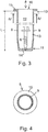
Figure 3 shows a longitudinal section of the sleeve, -
Figure 4 shows section IV-IV fromFigure 3 , -
Figure 5 shows section V-V fromFigure 1 , and -
Figure 6 shows an alternative for the attachment of the flashing ofFigure 5 . -
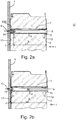
Figures 1 , and2b show a fastening system for fastening sandwich-structuredcomposite panels 1 to asupport structure 2. The sandwich-structuredcomposite panel 1 may be a façade cladding panel element, or a partition wall panel element, or a ceiling panel element. The fastening system comprises a sandwich-structuredcomposite panel 1 comprising afirst face skin 3 of sheet metal, asecond face skin 4 of sheet metal, and acore 5 made of thermally insulating material arranged between thefirst face skin 3 and thesecond face skin 4. Thecore 5 may comprise foamed polyurethane or foamed polyisocyanurate (PIR) or mineral wool. Thecore 5 may be a board of foamed polyurethane or foamed polyisocyanurate (PIR) or mineral wool or a combination thereof. Thefirst face skin 3 and thesecond face skin 4 are attached to thecore 5. As shown inFigure 2b , the fastening system further comprises a fastener 6 for fastening the sandwich-structuredcomposite panel 1 to thesupport structure 2. The fastener 6 may be a a metal screw, a wood screw, a self-drilling screw, a self-tapping screw or a concrete fastener. The type of the fastener is chosen suitably depending on the structure and material of the support structure 2 (e.g. metal, wood or concrete). The fastening system comprises aninstallation hole 7 formed through thefirst face skin 3 and thecore 5. Anelongated sleeve 8 is insertable into theinstallation hole 7. Thesleeve 8 is made of non-metallic, galvanically isolating and thermally insulating material. Preferably the sleeve is made of plastic-based material. Thesleeve 8 comprises atubular portion 9 having afirst end 10 and asecond end 11. Ahollow interior 12 is defined by aside wall 13 of thetubular portion 9. Abottom wall 14 is at asecond end 11. Acollar flange 15 encircles anopen mouth 16 at thefirst end 10. - In the embodiment of
Figure 2a not part of the present invention, thesleeve 8 has a length L1 extending in theinstallation hole 7 from thefirst face skin 3 towards thesecond face skin 4 to a shorter distance than the thickness of thepanel 1. Thesleeve 8 forms an installation guide for the fastener 6 which is insertable into the interior 12 of thesleeve 8 and fastenable through thebottom wall 14 of thesleeve 8. When thesleeve 8 is in theinstallation hole 7, thecollar flange 15 abuts against anouter surface 18 of thefirst face skin 3 and the fastener 6 being fastened to thesupport structure 2 pressing thesecond face skin 4 against thesupport structure 2. InFigure 2a there is amember 100 of resilient material installed between thebottom wall 14 of the sleeve and theinner surface 17 of thesecond face skin 4. - In the
Figure 2b thesleeve 8 has a length L2 corresponding to a combined thickness of thecore 5 and thefirst face skin 3. Thesleeve 8 forms an installation guide for the fastener 6 which is insertable into the interior 12 and fastenable through thebottom wall 14. When thesleeve 8 is in theinstallation hole 7, thebottom wall 14 abuts against aninner surface 17 of thesecond face skin 4 and thecollar flange 15 abuts against anouter surface 18 of thefirst face skin 3. When the fastener 6, in this example self-drilling screw 6, is screwed through thesecond face skin 4 to thesupport structure 2, the screwhead of the screw 6 becomes pressed against the wall bottom 14, and the wall bottom 14 presses thesecond face skin 4 firmly against thesupport structure 2. -
Figure 3 shows that in one embodiment thesleeve 8 is equipped with a fastener 6 which is pre-installed in theinterior 12 of thesleeve 8, so that the fastener 6 is readily fastenable after thesleeve 8 has been installed into theinstallation hole 7 of thepanel 1 at the building site. Thesleeve 8 may be either factory installed in theinstallation hole 7, or thesleeve 8 can be installed therein at the building site. The installation holes 7 are factory made in thepanel 1. The diameter of theinstallation hole 7 is of theorder 20 ... 25 mm, for example. Respectively, the outer diameter of thetubular portion 9 of thesleeve 8 is 20 ... 25 mm, for example. The first face skin and the second face skin may be made of aluminum or steel. The thickness of the first face skin and the second face skin is less than 1 mm, preferably 0,5 ... 0,6 mm. The thickness of thepanel 1 may be e.g. 100 ... 230 mm. - As shown in
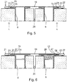
Figure 1 , right-hand side, the fastening system may comprise a flashing 19 to cover aseam 20 between two sandwich-structuredcomposite panels 1 which are adjacently next to each other. Reference is also made toFigures 5 and 6 . The flashing 19 has two parallellongitudinal edges overbent portion 23 forming aU-shaped groove 24. - In the embodiment of
Figure 5 the flashing 19 is attached by the aid of thecollar flanges 15 of thesleeves 8. Thecollar flange 15 comprises a steppedflange portion 25 insertable to saidU-shaped groove 24 for attaching the flashing 19. - In another embodiment shown in
Figure 6 , the fastening system comprises acap 26 attachable to themouth 16 of thesleeve 8. Thecap 26 has acap flange portion 27 extending over and beyond the periphery of thecollar flange 15 of thesleeve 8. The flashing 19 is attached by the aid of thecap flange portions 27 which are insertable to theU-shaped groove 24 for attaching the flashing 19. -
Figure 6 , on the left-hand side, shows an example wherein thecap 16 may be attached onto themouth 16 of thesleeve 8 by an annular snap-fit joint.Figure 6 , on the right-hand side shows another example wherein thecap 16 may be attached onto themouth 16 of thesleeve 8 by a threaded joint. - The attachment of the flashing with the aid of the sleeves or caps enables that no screw holes need to be made to the panels. Thus, re-usability of the panel is not limited.
- The fastening system has at least the following benefits:
- Easier, faster and cheaper installation of sandwich panels & flashings
- Less handling of screws on building site
- No more bucking failures in outer face due to overtightening of screws
- Savings in screws (shorter screws, no or less screws for flashings)
- Usually no need for stainless steel screws because no contact to outdoor conditions
- No thermal bridges due to screws
- Better shear resistance of screw connection because the screw contacts with internal sheet, also easier to use thicker screws if needed
- No extra screw holes needed for panels causing better re-usability
- Galvanic contact between external and internal sheeting is prevented. The interior of the sleeve provides a space, for example, for condition monitoring sensors which can be installed into the interior
- screw self-drilling and tapping waste metal is found less on the panel outer surface. This is likely to improve the outlook of assembly in some cases (possible rusting stains caused from water and drilled metal waste which is sometimes visible at least with white or light color surfaces). While the present inventions have been described in connection with a number of exemplary embodiments, and implementations, the present inventions are not so limited, but rather cover various modifications, and equivalent arrangements, which fall within the scope of the claims.
Claims (13)
- A fastening system for fastening sandwich-structured composite panels (1) to a support structure (2), the fastening system comprising- a sandwich-structured composite panel (1) comprising a first face skin (3) of sheet metal, a second face skin (4) of sheet metal, and a core (5) made of thermally insulating material arranged between the first face skin and the second face skin, the first and second face skins being attached to the core, and- a fastener (6) for fastening the sandwich-structured composite panel (1) to the support structure (2), the fastening system comprising an installation hole (7) formed through the first face skin (3) and the core (5), and an elongated sleeve (8) insertable into the installation hole (7), the sleeve (8) being made of non-metallic, galvanically isolating and thermally insulating material, the sleeve (8) comprising a tubular portion (9) having a first end (10), a second end (11), a hollow interior (12) defined by a side wall (13) of the tubular portion (9), a bottom wall (14) at a second end (11) and a collar flange (15) encircling an open mouth (16) at the first end (10), the sleeve (8) having a length (L1, L2) extending in the installation hole (7) from the first face skin (3) towards the second face skin (4), whereby the sleeve (8) forms an installation guide for the fastener (6) which is insertable into the interior (12) and fastenable through the bottom wall (14) whereby, when the sleeve (8) is in the installation hole (7), the collar flange (15) abuts against an outer surface (18) of the first face skin (3) and the fastener (6) being fastened to the support structure (2) pressing the second face skin (4) against the support structure (2), characterized in that the sleeve (8) has a length (L) corresponding to a combined thickness of the core (5) and the first face skin (3), whereby when the sleeve (8) is in the installation hole (7), the bottom wall (14) abuts against an inner surface (17) of the second face skin (4).
- The fastening system according to claim 1, characterized in that the fastener (6) is at least one of a metal screw, a wood screw, a self-drilling screw, a self-tapping screw, a concrete fastener.
- The fastening system according to any one of the claims 1 to 2, characterized in that the sleeve (8) is made of plastic-based material.
- The fastening system according to any one of the claims 1 to 3, characterized in that the core (5) comprises foamed polyurethane.
- The fastening system according to any one of the claims 1 to 4, characterized in that the core (5) comprises polyisocyanurate (PIR).
- The fastening system according to any one of the claims 1 to 5, characterized in that the core (5) comprises mineral wool.
- The fastening system according to any one of the claims 1 to 6, characterized in that the core (5) is a board of foamed polyurethane or a board of polyisocyanurate or a board of mineral wool or any combination thereof.
- The fastening system according to any one of the claims 1 to 7, characterized in that the sandwich-structured composite panel (1) is a façade cladding panel element, or a partition wall panel element, or a ceiling panel element.
- The fastening system according to any one of the claims 1 to 8, characterized in that the fastening system comprises a flashing (19) to cover a seam (20) between two sandwich-structured composite panels (1) which are adjacently next to each other, the flashing (19) having two parallel longitudinal edges (21, 22) both of the edges having an overbent portion (23) forming a U-shaped groove (24).
- The fastening system according to claim 9, c h a racterized in that the flashing (19) is attached by the aid of the collar flanges (15) of the sleeves (8) .
- The fastening system according to claim 10, c h a racterized in that the collar flange (15) comprises a stepped flange portion (25) insertable to said U-shaped groove (24) for attaching the flashing (19).
- The fastening system a according to claim 9, characterized in that the fastening system comprises a cap (26) attachable to the mouth (16) of the sleeve (8); the cap (26) having a cap flange portion (27) extending over and beyond the periphery of the collar flange (15) of the sleeve (8); and that the flashing (19) is attached by the aid of the cap flange portions (27), the cap flange portions being insertable to said U-shaped groove (24) for attaching the flashing (19) .
- Use of the fastening system according to any one of the claims 1 to 12 for fastening of sandwich-structured composite façade cladding panel elements or partition wall panel elements or ceiling panel elements to a support structure.
Priority Applications (3)
| Application Number | Priority Date | Filing Date | Title |
|---|---|---|---|
| PL19179936T PL3751069T3 (en) | 2019-06-13 | 2019-06-13 | Fastening system for fastening sandwich-structured composite panels to a support structure |
| LTEP19179936.0T LT3751069T (en) | 2019-06-13 | 2019-06-13 | Fastening system for fastening sandwich-structured composite panels to a support structure |
| EP19179936.0A EP3751069B1 (en) | 2019-06-13 | 2019-06-13 | Fastening system for fastening sandwich-structured composite panels to a support structure |
Applications Claiming Priority (1)
| Application Number | Priority Date | Filing Date | Title |
|---|---|---|---|
| EP19179936.0A EP3751069B1 (en) | 2019-06-13 | 2019-06-13 | Fastening system for fastening sandwich-structured composite panels to a support structure |
Publications (2)
| Publication Number | Publication Date |
|---|---|
| EP3751069A1 EP3751069A1 (en) | 2020-12-16 |
| EP3751069B1 true EP3751069B1 (en) | 2021-11-10 |
Family
ID=67180490
Family Applications (1)
| Application Number | Title | Priority Date | Filing Date |
|---|---|---|---|
| EP19179936.0A Active EP3751069B1 (en) | 2019-06-13 | 2019-06-13 | Fastening system for fastening sandwich-structured composite panels to a support structure |
Country Status (3)
| Country | Link |
|---|---|
| EP (1) | EP3751069B1 (en) |
| LT (1) | LT3751069T (en) |
| PL (1) | PL3751069T3 (en) |
Citations (1)
| Publication number | Priority date | Publication date | Assignee | Title |
|---|---|---|---|---|
| US4653246A (en) * | 1984-01-05 | 1987-03-31 | Hepler Jacque P | Insulation board for attachment to walls |
Family Cites Families (4)
| Publication number | Priority date | Publication date | Assignee | Title |
|---|---|---|---|---|
| IT1028941B (en) * | 1975-04-11 | 1979-02-10 | Scanalpina Spa | INSULATING PANELS AND CONSTRUCTION AND ASSEMBLY PROCEDURE OF THE SAME |
| DE3931833A1 (en) * | 1989-09-23 | 1991-04-04 | Hilti Ag | FASTENING ELEMENT FOR FASTENING INSULATION PANELS |
| ES1065136Y (en) * | 2007-03-28 | 2007-09-16 | Curbiperfil S A | FLAT DECORATIVE CLOSURE DEVICE FOR COVERS AND FACADES OF LARGE LENGTHS |
| PL68194Y1 (en) * | 2008-06-26 | 2016-01-29 | Żebrowski Tomasz Swal | Element for fixing insulation boards |
-
2019
- 2019-06-13 LT LTEP19179936.0T patent/LT3751069T/en unknown
- 2019-06-13 PL PL19179936T patent/PL3751069T3/en unknown
- 2019-06-13 EP EP19179936.0A patent/EP3751069B1/en active Active
Patent Citations (1)
| Publication number | Priority date | Publication date | Assignee | Title |
|---|---|---|---|---|
| US4653246A (en) * | 1984-01-05 | 1987-03-31 | Hepler Jacque P | Insulation board for attachment to walls |
Also Published As
| Publication number | Publication date |
|---|---|
| PL3751069T3 (en) | 2022-03-07 |
| EP3751069A1 (en) | 2020-12-16 |
| LT3751069T (en) | 2021-12-27 |
Similar Documents
| Publication | Publication Date | Title |
|---|---|---|
| US6131360A (en) | Plastic anchor system for use with masonry over steel stud back-up walls | |
| CN108678294B (en) | Assembled metal roof ridge node and installation method thereof | |
| US11035121B2 (en) | Thermal and acoustic insulating and sealing system for a safing slot in a curtain wall | |
| US3302350A (en) | Molding construction | |
| US9869086B2 (en) | Thermal insulating and sealing means for a safing slot in a curtain wall | |
| EP3458653B1 (en) | Building construction having a curtain wall comprising a thermal and acoustic insulating and sealing system of a safing slot | |
| EP1179645B2 (en) | Wall for a building facade | |
| US5694724A (en) | Vent pipe cover | |
| CN109139657B (en) | Screw with a multiple-start underhead thread and fastening system therefor | |
| US7107732B2 (en) | Purlin clip for an insulated ceiling of a metal building | |
| KR20150094366A (en) | Outer insulation system and installation method of outer wall using it | |
| EP3751069B1 (en) | Fastening system for fastening sandwich-structured composite panels to a support structure | |
| GB2187408A (en) | Self-tapping screw | |
| EP2759656A1 (en) | Exterior heat insulation cover panel | |
| ATE215158T1 (en) | INSULATION ELEMENT FOR CLAMPING FASTENING BETWEEN ROOF RAFTERS OR BEAMS OF OTHER WOODEN CONSTRUCTIONS | |
| JP6108578B2 (en) | Construction panel connection structure | |
| JP2016148243A (en) | Connection structure for construction panel | |
| KR20160089650A (en) | Exterior panel system for building and install method thereof | |
| EP2703574A2 (en) | Insulating element | |
| US20250327309A1 (en) | Isolator pad for a bracket for a façade cladding system | |
| RU2533463C1 (en) | Method to join folded roof with timbers and insulant | |
| KR20060026237A (en) | Steel column with excellent workability and fire resistance | |
| US5060429A (en) | Ceiling-wall attachment | |
| JP6599141B2 (en) | Crush prevention device and composite panel | |
| RU2123564C1 (en) | Guarding structure |
Legal Events
| Date | Code | Title | Description |
|---|---|---|---|
| PUAI | Public reference made under article 153(3) epc to a published international application that has entered the european phase |
Free format text: ORIGINAL CODE: 0009012 |
|
| STAA | Information on the status of an ep patent application or granted ep patent |
Free format text: STATUS: THE APPLICATION HAS BEEN PUBLISHED |
|
| AK | Designated contracting states |
Kind code of ref document: A1 Designated state(s): AL AT BE BG CH CY CZ DE DK EE ES FI FR GB GR HR HU IE IS IT LI LT LU LV MC MK MT NL NO PL PT RO RS SE SI SK SM TR |
|
| AX | Request for extension of the european patent |
Extension state: BA ME |
|
| STAA | Information on the status of an ep patent application or granted ep patent |
Free format text: STATUS: REQUEST FOR EXAMINATION WAS MADE |
|
| 17P | Request for examination filed |
Effective date: 20210125 |
|
| RBV | Designated contracting states (corrected) |
Designated state(s): AL AT BE BG CH CY CZ DE DK EE ES FI FR GB GR HR HU IE IS IT LI LT LU LV MC MK MT NL NO PL PT RO RS SE SI SK SM TR |
|
| RIN1 | Information on inventor provided before grant (corrected) |
Inventor name: KESTI, JYRKI Inventor name: HONKAKOSKI, ERKKI |
|
| GRAP | Despatch of communication of intention to grant a patent |
Free format text: ORIGINAL CODE: EPIDOSNIGR1 |
|
| STAA | Information on the status of an ep patent application or granted ep patent |
Free format text: STATUS: GRANT OF PATENT IS INTENDED |
|
| INTG | Intention to grant announced |
Effective date: 20210705 |
|
| GRAS | Grant fee paid |
Free format text: ORIGINAL CODE: EPIDOSNIGR3 |
|
| GRAA | (expected) grant |
Free format text: ORIGINAL CODE: 0009210 |
|
| STAA | Information on the status of an ep patent application or granted ep patent |
Free format text: STATUS: THE PATENT HAS BEEN GRANTED |
|
| AK | Designated contracting states |
Kind code of ref document: B1 Designated state(s): AL AT BE BG CH CY CZ DE DK EE ES FI FR GB GR HR HU IE IS IT LI LT LU LV MC MK MT NL NO PL PT RO RS SE SI SK SM TR |
|
| REG | Reference to a national code |
Ref country code: GB Ref legal event code: FG4D |
|
| REG | Reference to a national code |
Ref country code: AT Ref legal event code: REF Ref document number: 1446230 Country of ref document: AT Kind code of ref document: T Effective date: 20211115 Ref country code: CH Ref legal event code: EP |
|
| REG | Reference to a national code |
Ref country code: DE Ref legal event code: R096 Ref document number: 602019009094 Country of ref document: DE |
|
| REG | Reference to a national code |
Ref country code: SE Ref legal event code: TRGR |
|
| REG | Reference to a national code |
Ref country code: IE Ref legal event code: FG4D |
|
| REG | Reference to a national code |
Ref country code: FI Ref legal event code: FGE |
|
| REG | Reference to a national code |
Ref country code: NO Ref legal event code: T2 Effective date: 20211110 |
|
| REG | Reference to a national code |
Ref country code: EE Ref legal event code: FG4A Ref document number: E021933 Country of ref document: EE Effective date: 20220128 |
|
| REG | Reference to a national code |
Ref country code: NL Ref legal event code: MP Effective date: 20211110 |
|
| REG | Reference to a national code |
Ref country code: AT Ref legal event code: MK05 Ref document number: 1446230 Country of ref document: AT Kind code of ref document: T Effective date: 20211110 |
|
| PG25 | Lapsed in a contracting state [announced via postgrant information from national office to epo] |
Ref country code: RS Free format text: LAPSE BECAUSE OF FAILURE TO SUBMIT A TRANSLATION OF THE DESCRIPTION OR TO PAY THE FEE WITHIN THE PRESCRIBED TIME-LIMIT Effective date: 20211110 Ref country code: BG Free format text: LAPSE BECAUSE OF FAILURE TO SUBMIT A TRANSLATION OF THE DESCRIPTION OR TO PAY THE FEE WITHIN THE PRESCRIBED TIME-LIMIT Effective date: 20220210 Ref country code: AT Free format text: LAPSE BECAUSE OF FAILURE TO SUBMIT A TRANSLATION OF THE DESCRIPTION OR TO PAY THE FEE WITHIN THE PRESCRIBED TIME-LIMIT Effective date: 20211110 |
|
| PG25 | Lapsed in a contracting state [announced via postgrant information from national office to epo] |
Ref country code: IS Free format text: LAPSE BECAUSE OF FAILURE TO SUBMIT A TRANSLATION OF THE DESCRIPTION OR TO PAY THE FEE WITHIN THE PRESCRIBED TIME-LIMIT Effective date: 20220310 Ref country code: PT Free format text: LAPSE BECAUSE OF FAILURE TO SUBMIT A TRANSLATION OF THE DESCRIPTION OR TO PAY THE FEE WITHIN THE PRESCRIBED TIME-LIMIT Effective date: 20220310 Ref country code: NL Free format text: LAPSE BECAUSE OF FAILURE TO SUBMIT A TRANSLATION OF THE DESCRIPTION OR TO PAY THE FEE WITHIN THE PRESCRIBED TIME-LIMIT Effective date: 20211110 Ref country code: HR Free format text: LAPSE BECAUSE OF FAILURE TO SUBMIT A TRANSLATION OF THE DESCRIPTION OR TO PAY THE FEE WITHIN THE PRESCRIBED TIME-LIMIT Effective date: 20211110 Ref country code: GR Free format text: LAPSE BECAUSE OF FAILURE TO SUBMIT A TRANSLATION OF THE DESCRIPTION OR TO PAY THE FEE WITHIN THE PRESCRIBED TIME-LIMIT Effective date: 20220211 |
|
| PG25 | Lapsed in a contracting state [announced via postgrant information from national office to epo] |
Ref country code: SM Free format text: LAPSE BECAUSE OF FAILURE TO SUBMIT A TRANSLATION OF THE DESCRIPTION OR TO PAY THE FEE WITHIN THE PRESCRIBED TIME-LIMIT Effective date: 20211110 Ref country code: SK Free format text: LAPSE BECAUSE OF FAILURE TO SUBMIT A TRANSLATION OF THE DESCRIPTION OR TO PAY THE FEE WITHIN THE PRESCRIBED TIME-LIMIT Effective date: 20211110 Ref country code: RO Free format text: LAPSE BECAUSE OF FAILURE TO SUBMIT A TRANSLATION OF THE DESCRIPTION OR TO PAY THE FEE WITHIN THE PRESCRIBED TIME-LIMIT Effective date: 20211110 Ref country code: ES Free format text: LAPSE BECAUSE OF FAILURE TO SUBMIT A TRANSLATION OF THE DESCRIPTION OR TO PAY THE FEE WITHIN THE PRESCRIBED TIME-LIMIT Effective date: 20211110 Ref country code: DK Free format text: LAPSE BECAUSE OF FAILURE TO SUBMIT A TRANSLATION OF THE DESCRIPTION OR TO PAY THE FEE WITHIN THE PRESCRIBED TIME-LIMIT Effective date: 20211110 Ref country code: CZ Free format text: LAPSE BECAUSE OF FAILURE TO SUBMIT A TRANSLATION OF THE DESCRIPTION OR TO PAY THE FEE WITHIN THE PRESCRIBED TIME-LIMIT Effective date: 20211110 |
|
| REG | Reference to a national code |
Ref country code: DE Ref legal event code: R097 Ref document number: 602019009094 Country of ref document: DE |
|
| PLBE | No opposition filed within time limit |
Free format text: ORIGINAL CODE: 0009261 |
|
| STAA | Information on the status of an ep patent application or granted ep patent |
Free format text: STATUS: NO OPPOSITION FILED WITHIN TIME LIMIT |
|
| 26N | No opposition filed |
Effective date: 20220811 |
|
| PG25 | Lapsed in a contracting state [announced via postgrant information from national office to epo] |
Ref country code: AL Free format text: LAPSE BECAUSE OF FAILURE TO SUBMIT A TRANSLATION OF THE DESCRIPTION OR TO PAY THE FEE WITHIN THE PRESCRIBED TIME-LIMIT Effective date: 20211110 |
|
| PG25 | Lapsed in a contracting state [announced via postgrant information from national office to epo] |
Ref country code: SI Free format text: LAPSE BECAUSE OF FAILURE TO SUBMIT A TRANSLATION OF THE DESCRIPTION OR TO PAY THE FEE WITHIN THE PRESCRIBED TIME-LIMIT Effective date: 20211110 |
|
| PG25 | Lapsed in a contracting state [announced via postgrant information from national office to epo] |
Ref country code: MC Free format text: LAPSE BECAUSE OF FAILURE TO SUBMIT A TRANSLATION OF THE DESCRIPTION OR TO PAY THE FEE WITHIN THE PRESCRIBED TIME-LIMIT Effective date: 20211110 |
|
| REG | Reference to a national code |
Ref country code: CH Ref legal event code: PL |
|
| REG | Reference to a national code |
Ref country code: BE Ref legal event code: MM Effective date: 20220630 |
|
| PG25 | Lapsed in a contracting state [announced via postgrant information from national office to epo] |
Ref country code: LU Free format text: LAPSE BECAUSE OF NON-PAYMENT OF DUE FEES Effective date: 20220613 Ref country code: LI Free format text: LAPSE BECAUSE OF NON-PAYMENT OF DUE FEES Effective date: 20220630 Ref country code: IE Free format text: LAPSE BECAUSE OF NON-PAYMENT OF DUE FEES Effective date: 20220613 Ref country code: FR Free format text: LAPSE BECAUSE OF NON-PAYMENT OF DUE FEES Effective date: 20220630 Ref country code: CH Free format text: LAPSE BECAUSE OF NON-PAYMENT OF DUE FEES Effective date: 20220630 |
|
| PG25 | Lapsed in a contracting state [announced via postgrant information from national office to epo] |
Ref country code: IT Free format text: LAPSE BECAUSE OF FAILURE TO SUBMIT A TRANSLATION OF THE DESCRIPTION OR TO PAY THE FEE WITHIN THE PRESCRIBED TIME-LIMIT Effective date: 20211110 Ref country code: BE Free format text: LAPSE BECAUSE OF NON-PAYMENT OF DUE FEES Effective date: 20220630 |
|
| GBPC | Gb: european patent ceased through non-payment of renewal fee |
Effective date: 20230613 |
|
| PG25 | Lapsed in a contracting state [announced via postgrant information from national office to epo] |
Ref country code: MK Free format text: LAPSE BECAUSE OF FAILURE TO SUBMIT A TRANSLATION OF THE DESCRIPTION OR TO PAY THE FEE WITHIN THE PRESCRIBED TIME-LIMIT Effective date: 20211110 Ref country code: CY Free format text: LAPSE BECAUSE OF FAILURE TO SUBMIT A TRANSLATION OF THE DESCRIPTION OR TO PAY THE FEE WITHIN THE PRESCRIBED TIME-LIMIT Effective date: 20211110 Ref country code: GB Free format text: LAPSE BECAUSE OF NON-PAYMENT OF DUE FEES Effective date: 20230613 |
|
| PG25 | Lapsed in a contracting state [announced via postgrant information from national office to epo] |
Ref country code: HU Free format text: LAPSE BECAUSE OF FAILURE TO SUBMIT A TRANSLATION OF THE DESCRIPTION OR TO PAY THE FEE WITHIN THE PRESCRIBED TIME-LIMIT; INVALID AB INITIO Effective date: 20190613 |
|
| PG25 | Lapsed in a contracting state [announced via postgrant information from national office to epo] |
Ref country code: MT Free format text: LAPSE BECAUSE OF FAILURE TO SUBMIT A TRANSLATION OF THE DESCRIPTION OR TO PAY THE FEE WITHIN THE PRESCRIBED TIME-LIMIT Effective date: 20211110 |
|
| PGFP | Annual fee paid to national office [announced via postgrant information from national office to epo] |
Ref country code: FI Payment date: 20250616 Year of fee payment: 7 |
|
| PGFP | Annual fee paid to national office [announced via postgrant information from national office to epo] |
Ref country code: DE Payment date: 20250618 Year of fee payment: 7 Ref country code: PL Payment date: 20250529 Year of fee payment: 7 |
|
| PGFP | Annual fee paid to national office [announced via postgrant information from national office to epo] |
Ref country code: LT Payment date: 20250530 Year of fee payment: 7 |
|
| PGFP | Annual fee paid to national office [announced via postgrant information from national office to epo] |
Ref country code: NO Payment date: 20250618 Year of fee payment: 7 |
|
| PGFP | Annual fee paid to national office [announced via postgrant information from national office to epo] |
Ref country code: LV Payment date: 20250618 Year of fee payment: 7 |
|
| PGFP | Annual fee paid to national office [announced via postgrant information from national office to epo] |
Ref country code: EE Payment date: 20250629 Year of fee payment: 7 |
|
| PGFP | Annual fee paid to national office [announced via postgrant information from national office to epo] |
Ref country code: SE Payment date: 20250618 Year of fee payment: 7 |
|
| PG25 | Lapsed in a contracting state [announced via postgrant information from national office to epo] |
Ref country code: TR Free format text: LAPSE BECAUSE OF FAILURE TO SUBMIT A TRANSLATION OF THE DESCRIPTION OR TO PAY THE FEE WITHIN THE PRESCRIBED TIME-LIMIT Effective date: 20211110 |