EP3750795B1 - Aerodynamischer oberflächennahtspleiss - Google Patents
Aerodynamischer oberflächennahtspleiss Download PDFInfo
- Publication number
- EP3750795B1 EP3750795B1 EP20173092.6A EP20173092A EP3750795B1 EP 3750795 B1 EP3750795 B1 EP 3750795B1 EP 20173092 A EP20173092 A EP 20173092A EP 3750795 B1 EP3750795 B1 EP 3750795B1
- Authority
- EP
- European Patent Office
- Prior art keywords
- edge panel
- skin
- edge
- plies
- tapered
- Prior art date
- Legal status (The legal status is an assumption and is not a legal conclusion. Google has not performed a legal analysis and makes no representation as to the accuracy of the status listed.)
- Active
Links
Images


Classifications
-
- B—PERFORMING OPERATIONS; TRANSPORTING
- B64—AIRCRAFT; AVIATION; COSMONAUTICS
- B64C—AEROPLANES; HELICOPTERS
- B64C1/00—Fuselages; Constructional features common to fuselages, wings, stabilising surfaces or the like
- B64C1/06—Frames; Stringers; Longerons ; Fuselage sections
- B64C1/12—Construction or attachment of skin panels
-
- B—PERFORMING OPERATIONS; TRANSPORTING
- B64—AIRCRAFT; AVIATION; COSMONAUTICS
- B64C—AEROPLANES; HELICOPTERS
- B64C3/00—Wings
- B64C3/26—Construction, shape, or attachment of separate skins, e.g. panels
-
- B—PERFORMING OPERATIONS; TRANSPORTING
- B64—AIRCRAFT; AVIATION; COSMONAUTICS
- B64C—AEROPLANES; HELICOPTERS
- B64C3/00—Wings
- B64C3/28—Leading or trailing edges attached to primary structures, e.g. forming fixed slots
-
- B—PERFORMING OPERATIONS; TRANSPORTING
- B64—AIRCRAFT; AVIATION; COSMONAUTICS
- B64F—GROUND OR AIRCRAFT-CARRIER-DECK INSTALLATIONS SPECIALLY ADAPTED FOR USE IN CONNECTION WITH AIRCRAFT; DESIGNING, MANUFACTURING, ASSEMBLING, CLEANING, MAINTAINING OR REPAIRING AIRCRAFT, NOT OTHERWISE PROVIDED FOR; HANDLING, TRANSPORTING, TESTING OR INSPECTING AIRCRAFT COMPONENTS, NOT OTHERWISE PROVIDED FOR
- B64F5/00—Designing, manufacturing, assembling, cleaning, maintaining or repairing aircraft, not otherwise provided for; Handling, transporting, testing or inspecting aircraft components, not otherwise provided for
- B64F5/10—Manufacturing or assembling aircraft, e.g. jigs therefor
-
- B—PERFORMING OPERATIONS; TRANSPORTING
- B29—WORKING OF PLASTICS; WORKING OF SUBSTANCES IN A PLASTIC STATE IN GENERAL
- B29C—SHAPING OR JOINING OF PLASTICS; SHAPING OF MATERIAL IN A PLASTIC STATE, NOT OTHERWISE PROVIDED FOR; AFTER-TREATMENT OF THE SHAPED PRODUCTS, e.g. REPAIRING
- B29C70/00—Shaping composites, i.e. plastics material comprising reinforcements, fillers or preformed parts, e.g. inserts
- B29C70/04—Shaping composites, i.e. plastics material comprising reinforcements, fillers or preformed parts, e.g. inserts comprising reinforcements only, e.g. self-reinforcing plastics
- B29C70/28—Shaping operations therefor
- B29C70/30—Shaping by lay-up, i.e. applying fibres, tape or broadsheet on a mould, former or core; Shaping by spray-up, i.e. spraying of fibres on a mould, former or core
- B29C70/38—Automated lay-up, e.g. using robots, laying filaments according to predetermined patterns
-
- B—PERFORMING OPERATIONS; TRANSPORTING
- B29—WORKING OF PLASTICS; WORKING OF SUBSTANCES IN A PLASTIC STATE IN GENERAL
- B29C—SHAPING OR JOINING OF PLASTICS; SHAPING OF MATERIAL IN A PLASTIC STATE, NOT OTHERWISE PROVIDED FOR; AFTER-TREATMENT OF THE SHAPED PRODUCTS, e.g. REPAIRING
- B29C70/00—Shaping composites, i.e. plastics material comprising reinforcements, fillers or preformed parts, e.g. inserts
- B29C70/04—Shaping composites, i.e. plastics material comprising reinforcements, fillers or preformed parts, e.g. inserts comprising reinforcements only, e.g. self-reinforcing plastics
- B29C70/28—Shaping operations therefor
- B29C70/54—Component parts, details or accessories; Auxiliary operations, e.g. feeding or storage of prepregs or SMC after impregnation or during ageing
- B29C70/545—Perforating, cutting or machining during or after moulding
-
- B—PERFORMING OPERATIONS; TRANSPORTING
- B29—WORKING OF PLASTICS; WORKING OF SUBSTANCES IN A PLASTIC STATE IN GENERAL
- B29L—INDEXING SCHEME ASSOCIATED WITH SUBCLASS B29C, RELATING TO PARTICULAR ARTICLES
- B29L2031/00—Other particular articles
- B29L2031/30—Vehicles, e.g. ships or aircraft, or body parts thereof
- B29L2031/3076—Aircrafts
- B29L2031/3085—Wings
-
- B—PERFORMING OPERATIONS; TRANSPORTING
- B64—AIRCRAFT; AVIATION; COSMONAUTICS
- B64C—AEROPLANES; HELICOPTERS
- B64C1/00—Fuselages; Constructional features common to fuselages, wings, stabilising surfaces or the like
- B64C2001/0054—Fuselage structures substantially made from particular materials
- B64C2001/0072—Fuselage structures substantially made from particular materials from composite materials
Definitions
- the disclosure relates generally to aircraft aerodynamic surfaces and more particularly to structures of such aerodynamic surfaces.
- the exterior surfaces of aircraft and other vehicles are often formed by a plurality of panels. Such panels typically need to be mechanically coupled to each other and/or to underlying aircraft structures. Gaps may form due to such coupling. Such gaps can lead to increased aerodynamic disturbance, increasing drag and decreasing generated lift. Reducing or eliminating such gaps can thus improve aircraft performance.
- splice straps are additional parts and generally require extra fasteners, shimming, sealing, or erosion shields. Fillers need to be applied as an additional step and typically require shimming or bonding.
- the laminar composite cover comprises a stack of layers, substantially all of the layers being shaped to form a joggle, each joggle comprising a first portion, a second portion where the layer extends substantially parallel with the first portion, and a ramp between the first and second portions where the layer extends at an angle to the first and second portions, the number of layers being substantially the same on both sides of the ramp.
- the second cover partially overlaps with the composite cover, and a clamp or fastener holds the covers together where they overlap.
- the covers have external sides which are substantially aligned with each other so as to form a smooth aerodynamic surface.
- Document US 2012/0132754 A1 states a second component of an aircraft structure having an aerodynamic contour, such as a wing skin and a wing leading edge panel, the first component having a joggle so that it includes a first area which surface belongs to the aircraft aerodynamic contour and a second area where the joint with the second component takes place, the second component having a surface belonging to the aircraft aerodynamic contour, in which the second component includes a chamfer-shaped ending that extends beyond the overlapping area where the joint with the first component takes place so that the gaps between the first component and the second component are minimized.
- an aerodynamic contour such as a wing skin and a wing leading edge panel
- Document US 2011/0233338 A1 states a joint between an aircraft wing box cover and a leading/trailing edge structure, the cover and the structure having flush aerodynamic outer surfaces, wherein the structure has an integrally formed land that extends over an inner surface of the cover, and the land of the structure is fastened to the cover, and also a method of forming the joint.
- Document US 2010/0247903 A1 states a part of composite material having a wedge between two zones, the second zone being shorter than the first zone, whose structure comprises from its outer surface to its inner surface: a first section formed from at least two continuous sheets extending parallel to its outer surface, the gradient of the wedge being between 20% and 50%; a wedge in the shape of a triangular prism with its larger surface dimensioned in such a way that it forms a wedge having a gradient of less than 20%; a second section formed by a plurality of continuous sheets extending parallel to the surface bounded by the said first section with the said wedge placed upon it; and a process for manufacture of the part.
- the aircraft structure includes an edge panel and a skin.
- the edge panel includes a first edge panel portion and a tapered second edge panel portion, where the first edge panel portion is a constant first thickness, where the tapered second edge panel portion includes a first end proximal to the first edge panel portion and a second end distal to the first edge panel portion, and where the tapered second edge panel portion decreases in thickness from a first end to a second end.
- the skin includes a first portion, a second portion, and a first bend disposed between the first portion and the second portion.
- the first portion and the second portion are of a substantially constant second thickness, where at least a part of the second portion is disposed below at least a part of the tapered second edge panel portion, and where the second thickness is greater than the first thickness.
- the skin further comprises a third portion and a second bend disposed between the second portion and the third portion, wherein the first portion is substantially parallel to the third portion, and wherein the third portion is disposed below the first edge panel portion; wherein the aircraft structure further includes a fastener coupling together the third portion and the first edge panel portion; wherein the tapered second edge panel portion is a multi-ply composite, and wherein the tapered second edge panel portion decreases in thickness by decreasing an amount of plies, wherein a ply drop offset proximate to the first end is greater than a ply drop offset proximate to the second end, and wherein the second bend is disposed proximate to the first end.
- aerodynamic surface lap splices can be utilized in aerodynamic structures.
- aerodynamic structures can include, for example, wings, empennages, tails, engine inlets or outlets, fuselages, or other surfaces of an aircraft.
- the aircraft structure can include an edge panel and a skin portion.
- the edge panel can include a first edge panel portion and a tapered second edge panel portion decreasing in thickness from a first end to a second end.
- the skin portion can include a first portion, a second portion, and a first bend disposed between the first portion and the second portion.
- aerodynamic lap splices described herein allows for two adjacent surface aerodynamic components to maintain a smooth aerodynamic contour between their interfaces. Furthermore, such aerodynamic surface lap splices allows for simplified installation of components, reducing or eliminating any need for fillers and reducing parts count and weight, while maintaining structure strength.
- Fig. 1 illustrates an aircraft in accordance with an the claimed invention.
- the aircraft 100 of Fig. 1 includes fuselage 170, wings 172, horizontal stabilizers 174, aircraft engines 176, and vertical stabilizer 178. Additionally, aircraft 100 can include communications electronics 110, controller 108, and communications channel 112.
- Aircraft 100 described in Fig. 1 is exemplary and it is appreciated that in other examples, aircraft 100 can include more or less components or include alternate configurations. Additionally, concepts described herein can be extended to other aircraft such as helicopters, drones, missiles, etc.
- Communications electronics 110 can be electronics for communication between aircraft 100 and other mobile or immobile structures (e.g., other aircrafts, vehicles, buildings, satellites, or other such structures). Communications electronics 110 can be disposed within fuselage 170, wings 172, horizontal stabilizers 174, vertical stabilizer 178, and/or another portion of aircraft 100. Communications electronics 110 can include an antenna for sending and receiving signals. Examples of various antenna configurations are described herein.
- Communications channel 112 can allow for communications between controller 108 and various other systems of aircraft 100. Accordingly, communications channel 112 can link various components of aircraft 100 to the controller 108. Communications channel 112 can, for example, be either a wired or a wireless communications system.
- Controller 108 can include, for example, a microprocessor, a microcontroller, a signal processing device, a memory storage device, and/or any additional devices to perform any of the various operations described herein.
- controller 108 and/or its associated operations can be implemented as a single device or multiple connected devices (e.g., communicatively linked through wired or wireless connections such as communications channel 112) to collectively constitute controller 108.
- Controller 108 can include one or more memory components or devices to store data and information.
- the memory can include volatile and non-volatile memory. Examples of such memory include RAM (Random Access Memory), ROM (Read-Only Memory), EEPROM (Electrically-Erasable Read-Only Memory), flash memory, or other types of memory.
- controller 108 can be adapted to execute instructions stored within the memory to perform various methods and processes described herein, including implementation and execution of control algorithms responsive to sensor and/or operator (e.g., flight crew) inputs.
- Aerodynamic surfaces can be surfaces that generate lift, downforce, and/or otherwise affect the stability or flight of the aircraft 100.
- aerodynamic surfaces utilizing the aerodynamic surface lap splices can be disposed at or near the leading or trailing edges of the wings 172, horizontal stabilizers 174, vertical stabilizers 178, aircraft engines 176, and/or fuselage 170.
- Fig. 2 illustrates an aircraft wing in accordance with an the claimed invention.
- Fig. 2 shows an aircraft wing 200 that includes a wing body 202 and a leading edge 210.
- the wing 200 can be divided into portions 204, 206, and 208.
- Portion 204 can be a leading portion.
- Portion 206 can be a middle portion.
- Portion 208 can be a trailing portion.
- the leading edge 210 of the aircraft wing 200 can be disposed within the portion 204.
- the aerodynamic surface lap splices described herein are disposed within the portion 204 (e.g., within the leading edge 210), but other examples can dispose the aerodynamic surface lap splices within portions 206 or 208.
- Figs. 3-4 illustrate side cutaway views of portions of aerodynamic structures utilizing aerodynamic surface lap splices in accordance with the claimed invention.
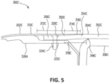
- Figs. 5-6 illustrate side cutaway views of portions of aerodynamic structures utilizing aerodynamic surface lap splices not belonging to the claimed invention.
- aerodynamic structure refers to any structure or component that interacts with airflow around the aircraft 100. That is, during operation of the aircraft 100, air can flow along at least a portion of such an aerodynamic structure. Examples of such aerodynamic structures can include wings, empennages, engine inlets and outlets, fuselages, tails, and other portions of the aircraft 100.
- the aerodynamic structure can be defined by one or more aerodynamic surfaces (e.g., surfaces subjected to airflow).
- Fig. 3 illustrates aerodynamic structure 300A that includes a lap splice that includes an edge panel 302A and a skin 304A.
- skin 304A is coupled to structural member 306A.
- Structural member 306A can provide structure support for the skin 304A and, hence, the edge panel 302A.
- the edge panel 302A can be an aerodynamic surface of the aircraft 100.
- the edge panel 302A includes a first edge panel portion 308A and a second edge panel portion 310A.
- the first edge panel portion 308A can, in certain examples, be the same thickness or thicker than the second edge panel portion 310A.
- the leading edge of the aerodynamic structure 300A can be a part of the first edge panel portion 308A.
- the first edge panel portion 308A can include a honeycomb disposed between composite layers such as carbon fiber, fiberglass, Kevlar ® , or other composites to increase the strength of the edge panel 302A. As such, the first edge panel portion 308A can be thicker than the second edge panel portion 310A.
- the second edge panel portion 310A can overhang the skin 304A.
- the second edge panel portion 310A can form at least a portion of a lap splice that couples together the edge panel 302A and the skin 304A.
- the second edge panel portion 310A includes a constant thickness portion 312A and a tapered portion 314A.
- the constant thickness portion 312A includes a first end of the second edge panel portion 310A. The first end can be disposed proximal (e.g., adjacent or next to) to the first edge panel portion 308A.
- the tapered portion 314A includes a second edge of the second edge panel portion 310A. The second end is disposed distal (e.g., away from) the first edge panel portion 308A. In certain examples, the second end can be, for example, the rightmost point of the edge panel 302A as shown in Fig. 3 .
- the constant thickness portion 312A is of a single constant thickness through the entire portion. Thus, where the first end is at a first edge of the constant thickness portion 312A, the constant thickness portion 312A is a single constant thickness from the first end to the other edge of the constant thickness portion 312A.
- the thickness of the skin 304A is greater than that of the thickness of the constant thickness portion 312A.
- the skin 304A can be thicker by three times or greater than that of the constant thickness portion 312A.
- the tapered portion 314A is disposed proximate to the constant thickness portion 312A.
- the tapered portion 312A decreases in thickness from the end proximate to the constant thickness portion 312A to the second end opposite that of the constant thickness portion 312A.
- the tapered portion 312A can be configured to disposed proximate to a jog of the skin 304A to form the lap splice or a portion thereof. Accordingly, the tapered portion 312A can include a ramp surface 316A disposed proximate to the skin 304A.
- the skin 304A can be disposed rearward of the edge panel 302A. That is, during operation of the aircraft 100, airflow can first pass over the edge panel 302A before flowing over the skin 304A. At least a portion of the skin 304A can be an aerodynamic surface of the aerodynamic structure 300A.
- the skin 304A includes a first portion 352A, a second portion 354A, and a third portion 356A.
- the second portion 354A is disposed at an angle to the first portion 352A due to a bend 348A.
- the third portion 356A is disposed at an angle to the second portion 354A due to a bend 350A.
- the first portion 352A, the second portion 354A, and the third portion 354C can form a joggle.
- the edge panel 302A is coupled to the skin 304A via one or more fasteners, such as fastener 322A.
- the edge panel 302A can be held relative to the skin 304A through bolt 324A.
- Fastener 322A can have a flush head 320A.
- the edge panel 302A and the skin 304A can include appropriate through holes to accommodate such fasteners.
- the flush head 320A does not substantially protrude (e.g., within +/-2 inches) from the surface of the edge panel 302A and so does not substantially disturb airflow over the surface of the edge panel 302A.
- the profile of the outer surface of the second portion 354A and/or the third portion 356A can substantially match that of the profile of the inner surface of the tapered portion 312A.
- the tapered portion 312A can be snugly positioned proximate to the skin 304A.
- the outer surface of the first portion 352A can be positioned to be substantially (e.g., within +/- 2 inches) planar with the outer surface of the edge panel 302A when end panel 302A is coupled to the skin 304A.
- the outer surface of the aerodynamic structure 300A can be relatively smooth when assembled, improving airflow over the surface of the aerodynamic structure 300A.
- the skin 304A or the portion of the skin 304A coupled to the edge panel 302A is of a substantially (e.g., +/- 10%) constant thickness. Fabricating the skin 304A as a substantially constant thickness can lower the production time or cost of the aircraft 100. As such, examples of the lap splice described herein can be produced in a cost effective and timely manner.
- the thickness of the tapered portion 314A and/or the second edge panel portion 310A can be significantly thinner than that of the skin 304A while the skin 304A is a constant thickness.
- the skin 304A can be a load bearing panel, the constant thickness of the skin 304A allows for a stronger component.
- the skin 304A can be coupled to structural member 306A through adhesives, welding, mechanical fasteners (e.g., bolts, rivets, and other fasteners), and/or through other techniques.
- the edge panel 302A can be a leading panel of the aerodynamic structure 300A. That is, the edge panel 302A can include a leading edge of the aerodynamic structure 300A. In certain such examples, the edge panel 302A can receive lower loads than that of other portions of the aerodynamic structure 300A. As such, the thin tapered section of the lap splice described herein can be a portion of the edge panel 302A (e.g., as part of tapered portion 314A) to minimize wasted weight and any needed structural strengthening.
- Figs. 4-6 illustrate additional examples of the aerodynamic structure, such as aerodynamic structures 300B-D, respectively.
- the examples shown in Figs. 4-6 as well as in Figs. 7 and 8 , are similar to that of Fig. 3 .
- the description of Fig. 3 can apply.
- Figs. 3 and 5 illustrate examples of lap splices for upper surfaces of the aerodynamic devices 300A and 300C, respectively.
- Figs. 4 and 6 illustrate examples of lap splices for lower surfaces of the aerodynamic devices 300B and 300D, respectively.
- Figs. 3 and 4 illustrate examples of lap splices for components between ribs of the respective aerodynamic devices.
- Figs. 5 and 6 illustrate examples lap splices for components on support fitting locations of the respective aerodynamic devices.
- Fig. 5 further illustrates aerodynamic device 300C with support structure 526A coupled to edge panel 302C, skin 304C, and structural member 306C through any of the techniques described herein (e.g., through adhesives, welding, mechanical fasteners such as fastener 322C, and/or other techniques).
- Fig. 6 illustrates aerodynamic device 300D with similar features to that of Fig. 5 , but for a lap splice used on a lower surface of the aerodynamic device 300D.
- fastener 322C can be disposed below edge panel 302C to further improve airflow over edge panel 302C.
- edge panel 302C cannot include a honeycomb as shown in Figs. 3 and 4 due to the support structure 526A being coupled to the edge panel 302C. Coupling the support structure 526A to the edge panel 302C can eliminate the need for the honeycomb.
- support structure 526B can be coupled to the edge panel 302D through one or more pins 530 with flush head 528 in addition to bolt 322D.
- the support structure 526B and the edge panel 302D can include appropriate through holes to accommodate the fasteners.
- Fig. 7 illustrates a side cutaway view of a portion of another aerodynamic structure utilizing an aerodynamic surface lap splice not belonging to the claimed invention.
- aerodynamic device 300E includes edge panel 302E and skin 304E.
- Edge panel 302E includes a constant thickness portion 312E and a tapered portion 314E.
- the skin 304E includes a first portion 352E, a second portion 354E, and a third portion 356E.
- the location of inner radius 730 of bend 350E between the second portion 354E and the third portion 356E can substantially (e.g., be within a foot) match the location of the bend at the transition between the constant thickness portion 312E and the tapered portion 314E.
- the radius of the bend at the transition between the constant thickness portion 312E and the tapered portion 314E can be less than inner radius 730.
- the skin 304E can be trimmed at edge 736. That is, for examples where the skin 304E is a composite skin, multiple layers of composites can be laid up during the manufacturing process. The layers can then be trimmed along edge 736 to form the skin 304E.
- the skin 304E can be a substantially constant thickness throughout and can be a multi-ply composite. The edges of the skin 304E can be trimmed.
- having the entire skin be a constant thickness can allow for easier manufacturing of the skin 304E as the plies can be laid and then trimmed with no need to form tapers.
- the composite plies can be laid with a tape laying machine or through another automated technique. Forming tapers in such automated processes can be difficult and, thus, forming skin 304E without a tapered section can allow for a simplified automated process.
- the vertical offset from the top of the first portion 352E to the top of the third portion 356E is referred to as the edge panel offset.
- the edge panel offset can substantially match that of the thickness of the second edge panel portion 310E. In certain examples, the edge panel offset can be in the range of 0.06 to 0.2 inches.
- Second portion 354E or portions thereof can be referred to as the joggle ramp.
- Such a joggle ramp can be the length of distance 318E.
- Distance 318E can be defined as running from the centerpoint of radius 730 to the centerpoint of the radius of bend 348E.
- the ratio of the distance 318E to the edge panel offset can be defined as the ramp ratio.
- a ramp ratio of 5:1 denotes that distance 318E is five times that of the edge panel offset.
- the ramp ratio of the aerodynamic devices described herein can be from 5:1 to 15:1.
- Fig. 8 illustrates a side cutaway view of a portion of a composite aerodynamic structure with an aerodynamic surface lap splice in accordance with the claimed invention.
- Fig. 8 illustrates a composite edge panel 302F.
- At least the second edge panel portion 310F of the edge panel 302F can be formed from a plurality of composite plies.
- the second edge panel portion 310F can include a constant thickness portion 312F and a tapered portion 314F.
- the number of plies within all of the constant thickness portion 312F can be the same, while the tapered portion 314F can have a decreasing number of plies to form the taper of the ramp surface 316F.
- the second edge panel portion 310F can be made from a plurality of plies 838A-E as well as additional plies.
- the plies 838A-E can each have different lengths and, thus, allow for the number of plies to decrease to form the taper of the ramp surface 316F.
- the distance between a first point where the number of plies decreases and a subsequent point where the number of plies decreases is called a ply drop.
- the ply drop of different portions is varied.
- the ply drop 842A between where ply 838A ends and where ply 838B ends is a longer distance (e.g., about 25% to 200% longer distance) than the ply drop 842B between where ply 838B ends and where ply 838C ends.
- the ply drop 842A is closer to the first end than the second end.
- the longer distance of the ply drop 842A can prevent the tapered portion 316F from interfering with the radius 730 of the skin 304E shown in Fig. 7 .
- the end of the edge panel 302F can additionally include a region 840 with a curl offset.
- the edge panel 302F can bend down slightly at the curl offset of the region 840 (e.g., bend downward by a distance of 20% or less of the thickness of the edge panel 302F). Such a curl offset can allow for a more flush fitment of the edge panel 302F to the corresponding skin.
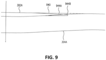
- Fig. 9 illustrates details of side cutaway views of portions of aerodynamic structures utilizing aerodynamic surface lap splices in accordance with the claimed invention.
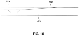
- Fig. 10 illustrates details of side cutaway views of portions of aerodynamic structures utilizing aerodynamic surface lap splices not belonging to the claimed invention.
- position 944A illustrates the position of the region 840 (shown in Fig. 8 ) with a curl offset when not coupled to the skin 304A.
- Position 944B illustrates the position of the region 840 when the edge panel 302A is coupled to the skin 304A. As shown, the region 840 has been pushed upward by the skin 304A and is now flush with the top of the surface of the skin 304A.
- a gap can still be present rearward of the edge panel 302A.
- Fig. 10 illustrates an example with filler 1046 disposed within the gap. Filler 1046 can allow for a smoother airflow transition between edge panel 302A and skin 304A.
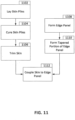
- Fig. 11 is a flowchart detailing a technique for forming a portion of an aircraft with an aerodynamic surface lap splice in accordance with an example of the disclosure. As shown in Fig. 11 , blocks 1102-1106 describe steps for forming a skin while blocks 1108 and 1110 describes steps for forming an edge panel.
- the plies of the skin are laid.
- the plies can be laid by a machine. Each ply can be laid on top of previously laid plies.
- the plies can be laid by, for example, an automated tape laying machine or another such automated system.
- the plies can be laid so that the skin is a constant thickness throughout.
- the plies can be preimpregnated with a resin or other filler, but other examples can apply the resin or other filler in a separate step.
- the skin plies are cured.
- the plies can be formed into a solid component in block 1104.
- the skin plies can be cured with one or more bends within the ply, forming different portions of the skin. One or more of those portions can be configured to be disposed underneath a portion of an edge panel.
- the skin can be trimmed to form the final shape of the desired skin.
- a portion of the edge panel can be formed.
- a honeycomb can be held in a first position and plies of composites disposed around the outside of the composite.
- the tapered portion of the edge panel can be formed. Certain examples can form the tapered portion while plies are laid (e.g., through laying of plies of different dimensions) while other examples can form the tapered portion after the plies are laid (e.g., through machining). Further examples of the edge panel can be made from a metallic material, and the tapered portion in such examples can be formed through machining, stamping, forging, or other techniques.
- the skin can be coupled to the edge panel in block 1112.
- the skin and the edge panel can be coupled to form an aerodynamic device.
- the edge panel and the skin can be coupled through any technique disclosed herein.
Landscapes
- Engineering & Computer Science (AREA)
- Aviation & Aerospace Engineering (AREA)
- Mechanical Engineering (AREA)
- Manufacturing & Machinery (AREA)
- Transportation (AREA)
- Laminated Bodies (AREA)
Claims (12)
- Luftfahrzeugstruktur aufweisend:ein Randpaneel (302A) aufweisend einen ersten Randpaneelabschnitt (312A) und einen verjüngten zweiten Randpaneelabschnitt (314A), wobei der erste Randpaneelabschnitt eine konstante erste Dicke aufweist, wobei der verjüngte zweite Randpaneelabschnitt (314A) ein erstes Ende proximal zu dem ersten Randpaneelabschnitt (312A) und ein zweites Ende distal zu dem ersten Randpaneelabschnitt (312A) aufweist, und wobei der verjüngte zweite Randpaneelabschnitt (314A) in der Dicke vom ersten Ende zu dem zweiten Ende abnimmt; undeine Haut (304A) aufweisend:einen ersten Abschnitt (352A);einen zweiten Abschnitt (354A); undeine erste Biegung (348A) angeordnet zwischen dem ersten Abschnitt (352A) und dem zweiten Abschnitt (354A), wobei der erste Abschnitt (352A) und der zweite Abschnitt (352A) eine im Wesentlichen konstante zweite Dicke aufweisen, wobei mindestens ein Teil des zweiten Abschnitts (354A) unterhalb mindestens eines Teils des verjüngten zweiten Randpaneelabschnitts (314A) angeordnet ist, und wobei die zweite Dicke größer ist als die erste Dicke;wobei die Haut des Weiteren einen dritten Abschnitt (356A) und eine zweite Biegung (350A) angeordnet zwischen dem zweiten Abschnitt (354A) und dem dritten Abschnitt (356A) aufweist, wobei der erste Abschnitt (352A) im Wesentlichen parallel zu dem dritten Abschnitt (356A) ist, und wobei der dritte Abschnitt (356A) unterhalb des erstenRandpaneelabschnitts (312A) angeordnet ist;wobei die Luftfahrzeugstruktur des Weiteren ein Befestigungselement (322A) aufweist, welches den dritten Abschnitt (356A) und den ersten Randpaneelabschnitt (312A) miteinander verbindet;wobei der verjüngte zweite Randpaneelabschnitt (314A) ein mehrlagiger Verbundwerkstoff ist, und wobei der verjüngte zweite Randpaneelabschnitt (314A) in der Dicke durch Verringerung der Anzahl der Lagen abnimmt,wobei ein Lagenabsatzversatz proximal zu dem ersten Ende größer ist als ein Lagenabsatzversatz proximal zu dem zweiten Ende, und wobei die zweite Biegung (350A) proximal zu dem ersten Ende angeordnet ist.
- Luftfahrzeugstruktur nach Anspruch 1, wobei das Randpaneel (302A) des Weiteren einen Wabenteil aufweist, der dicker ist als der erste Randpaneelabschnitt (312A) und der verjüngte zweite Randpaneelabschnitt (314A), und wobei der Wabenteil eine Wabe aufweist, die zwischen einer Vielzahl von Lagen angeordnet ist.
- Luftfahrzeugstruktur nach einem der vorhergehenden Ansprüche, wobei die Haut (304A) ein mehrlagiger Verbundwerkstoff ist, und wobei die Anzahl der Lagen in der gesamten Haut (304A) gleichbleibend ist.
- Luftfahrzeugstruktur nach einem der vorhergehenden Ansprüche, wobei das Randpaneel (302A) eine Vorder- oder Hinterkante eines Flügels oder eines Leitwerks aufweist.
- Luftfahrzeugstruktur nach einem der vorhergehenden Ansprüche, des Weiteren aufweisend: einen Luftfahrzeugstrukturteil (306A) gekoppelt an die Haut (304A); und ein mechanisches Befestigungselement, welches die Haut (304A) und den Luftfahrzeugstrukturteil (306A) miteinander verbindet.
- Luftfahrzeugstruktur nach einem der vorhergehenden Ansprüche, wobei das zweite Ende eine Kantenkrümmung aufweist.
- Luftfahrzeugstruktur nach einem der vorhergehenden Ansprüche, wobei die zweite Dicke mindestens dreimal so groß ist wie die erste Dicke.
- Luftfahrzeug aufweisend die Luftfahrzeugstruktur nach einem der Ansprüche 1 bis 7, das Luftfahrzeug aufweisend: einen Rumpf (170); und einen Flügel (172), wobei die Luftfahrzeugstruktur zumindest teilweise innerhalb des Flügels angeordnet ist.
- Verfahren zur Herstellung der Luftfahrzeugstruktur nach einem der Ansprüche 1 bis 8, das Verfahren aufweisend:Bilden der Haut (304A) durch:Auflegen einer Vielzahl von Verbundhautlagen; undAushärten der Vielzahl von Verbundhautlagen, wobei die Anzahl der Hautlagen in der gesamten Haut (304A) gleichbleibend ist;Bilden des Randpaneels (302A) durch:Auflegen einer Vielzahl von Verbundrandlagen, wobei der verjüngte zweite Randpaneelabschnitt (314A) durch Verringerung der Anzahl der Randlagen entlang des verjüngten zweiten Randpaneelabschnitts (314A) gebildet wird, wobei ein Lagenabsatzversatz proximal zu dem ersten Ende größer ist als ein Lagenabsatzversatz proximal zu dem zweiten Ende, und wobei die zweite Biegung (350A) proximal zu dem ersten Ende angeordnet ist; undAushärten der Vielzahl von Verbundrandlagen; undwobei das Verfahren des Weiteren aufweisend das Koppeln der Haut (304A) an das Randpaneel (302A) mittels eines Befestigungselements (322A).
- Verfahren nach Anspruch 9, wobei ein automatisiertes Gerät das Auflegen der Vielzahl von Verbundhautlagen ausführt, und wobei das Bilden der Haut des Weiteren das Trimmen einer Kante der Haut (304A) aufweist.
- Verfahren nach Anspruch 9 oder 10, wobei das Bilden des Randpaneels (302A) des Weiteren das Anordnen eines Wabenteils zwischen mindestens zwei der Verbundrandlagen umfasst.
- Verfahren nach einem der vorhergehenden Ansprüche, des Weiteren aufweisend: bilden mindestens des verjüngten zweiten Randpaneelabschnitts (314A) des Randpaneels (302A) durch das Bearbeiten eines Metallrohlings.
Applications Claiming Priority (1)
| Application Number | Priority Date | Filing Date | Title |
|---|---|---|---|
| US16/438,369 US11383820B2 (en) | 2019-06-11 | 2019-06-11 | Aerodynamic surface lap splice |
Publications (2)
| Publication Number | Publication Date |
|---|---|
| EP3750795A1 EP3750795A1 (de) | 2020-12-16 |
| EP3750795B1 true EP3750795B1 (de) | 2024-08-14 |
Family
ID=70553954
Family Applications (1)
| Application Number | Title | Priority Date | Filing Date |
|---|---|---|---|
| EP20173092.6A Active EP3750795B1 (de) | 2019-06-11 | 2020-05-06 | Aerodynamischer oberflächennahtspleiss |
Country Status (4)
| Country | Link |
|---|---|
| US (1) | US11383820B2 (de) |
| EP (1) | EP3750795B1 (de) |
| JP (1) | JP7448410B2 (de) |
| CN (1) | CN112061370B (de) |
Families Citing this family (2)
| Publication number | Priority date | Publication date | Assignee | Title |
|---|---|---|---|---|
| DE102019117627B4 (de) * | 2019-06-30 | 2026-01-15 | Airbus Operations Gmbh | Elektronikanordnung für ein Flugzeug und Verfahren zum Bereitstellen einer solchen Elektronikanordnung |
| GB2599161A (en) * | 2020-09-29 | 2022-03-30 | Airbus Operations Ltd | A cover panel |
Family Cites Families (22)
| Publication number | Priority date | Publication date | Assignee | Title |
|---|---|---|---|---|
| US4888451A (en) * | 1988-11-29 | 1989-12-19 | United Technologies Corporation | Electrical continuity means for composite joints |
| FR2866626B1 (fr) * | 2004-02-20 | 2006-05-19 | Airbus France | Arret de raidisseur a pentes decalees et panneau muni d'un tel arret |
| US20060251496A1 (en) * | 2004-07-09 | 2006-11-09 | Bae Systems Plc | Fastener arrangement for fastening a detachable panel |
| GB0525896D0 (en) * | 2005-12-20 | 2006-02-01 | Airbus Uk Ltd | A joint for use in aircraft construction |
| JP4657194B2 (ja) * | 2006-11-20 | 2011-03-23 | 本田技研工業株式会社 | 前縁スキンの段差調整構造および前縁スキンの組付方法 |
| GB0624208D0 (en) * | 2006-12-04 | 2007-01-10 | Airbus Uk Ltd | Composite structure |
| US8398027B2 (en) * | 2007-09-17 | 2013-03-19 | The Boeing Company | Method and apparatus for reinforcing composite structures |
| US8016237B2 (en) | 2007-12-12 | 2011-09-13 | The Boeing Company | Methods and apparatus for an integrated aerodynamic panel |
| GB0802938D0 (en) * | 2008-02-19 | 2008-03-26 | Airbus Uk Ltd | Clamped friction joint |
| GB0805268D0 (en) * | 2008-03-25 | 2008-04-30 | Airbus Uk Ltd | Composite joint protection |
| ES2384920B1 (es) * | 2009-03-31 | 2013-05-21 | Airbus Operations, S.L. | Pieza de material con una rampa entre dos zonas. |
| FR2947523B1 (fr) * | 2009-07-03 | 2011-07-22 | Airbus Operations Sas | Element de fuselage comportant un troncon de fuselage et des moyens de jonction |
| GB201004757D0 (en) * | 2010-03-23 | 2010-05-05 | Airbus Operations Ltd | Joint |
| ES2396882B1 (es) * | 2010-11-30 | 2014-01-29 | Airbus Operations, S.L. | Disposición de interfaz entre dos componentes de una estructura de una aeronave. |
| ES2396843B1 (es) | 2010-11-30 | 2014-01-29 | Airbus Operations, S.L. | Disposición de interfaz entre dos componentes de una estructura de una aeronave usando una pieza intermedia. |
| ES2426111B1 (es) | 2012-04-17 | 2015-03-24 | Airbus Operations S.L. | Interfaz para superficie de sustentación de aeronave |
| US10329009B2 (en) * | 2014-09-17 | 2019-06-25 | The Boeing Company | Composite wing edge attachment and method |
| EP3243744B1 (de) * | 2016-05-11 | 2019-05-01 | Airbus Operations Limited | Flugzeugverbindung |
| JP6949474B2 (ja) | 2016-11-24 | 2021-10-13 | 三菱重工業株式会社 | 複合材及び複合材の成形方法 |
| US11046029B2 (en) | 2017-06-02 | 2021-06-29 | Jamco Corporation | Method for producing composite material component and device for producing composite material component |
| US10773789B2 (en) * | 2017-07-07 | 2020-09-15 | The Boeing Company | Skin-panel interface of an aircraft |
| JP6980454B2 (ja) * | 2017-08-17 | 2021-12-15 | 三菱重工業株式会社 | 複合材の設計方法、複合材の評価方法及び複合材 |
-
2019
- 2019-06-11 US US16/438,369 patent/US11383820B2/en active Active
-
2020
- 2020-04-21 JP JP2020075370A patent/JP7448410B2/ja active Active
- 2020-05-06 EP EP20173092.6A patent/EP3750795B1/de active Active
- 2020-05-29 CN CN202010478596.1A patent/CN112061370B/zh active Active
Also Published As
| Publication number | Publication date |
|---|---|
| US20200391842A1 (en) | 2020-12-17 |
| EP3750795A1 (de) | 2020-12-16 |
| JP2020200021A (ja) | 2020-12-17 |
| CN112061370A (zh) | 2020-12-11 |
| JP7448410B2 (ja) | 2024-03-12 |
| US11383820B2 (en) | 2022-07-12 |
| CN112061370B (zh) | 2024-09-24 |
Similar Documents
| Publication | Publication Date | Title |
|---|---|---|
| EP3138769B1 (de) | Radiusfüllstoffhaltige vertikallagenstapel und dünnlagen | |
| US6190484B1 (en) | Monolithic composite wing manufacturing process | |
| EP3030413B1 (de) | Versteifte verbundplatten und verfahren zu deren herstellung | |
| EP2153979B1 (de) | Aus verbundwerkstoff hergestellter torsionskasten mit mehreren holmen | |
| EP2766258B1 (de) | Faserverbundpanel aufweisend verjüngte und gebogene stringers | |
| EP3287361B1 (de) | Mit planken belegte stringer, die eine strukturstütze für einen flugzeugflügel bieten | |
| CN102241275B (zh) | 弯曲的复合框架及其制造方法 | |
| US9862479B1 (en) | Methods of making and structures containing stiffeners having transition portions | |
| US20110024562A1 (en) | Method for manufacturing a fibre-composite component, fibre-composite component and fibre-composite fuselage component of an aircraft | |
| US10207789B2 (en) | Aircraft composite wingbox integration | |
| US20120009372A1 (en) | Structural panel with integrated stiffening | |
| EP3750795B1 (de) | Aerodynamischer oberflächennahtspleiss | |
| CN107107485A (zh) | 制造复合结构的垫片的方法以及包含垫片的复合结构 | |
| CN108622434B (zh) | 制造航空航天结构的方法和系统及损伤容限型格栅翼肋结构 | |
| US8708279B2 (en) | Composite structural member with progressive rigidity | |
| JP2011240925A5 (de) | ||
| US11577816B2 (en) | Composite laminate for an airframe lifting surface and method for manufacturing thereof | |
| EP2982598A2 (de) | Seitliches lagen-layup eines verbundholms | |
| US20160039513A1 (en) | Longitudinal ply layup of composite spar | |
| US20250135744A1 (en) | Composite structure with steered fibres | |
| US20240140588A1 (en) | Aircraft wing structure | |
| US20230321928A1 (en) | Composite part with crossbeam supports and methods of forming composite parts | |
| EP3401207B1 (de) | Systeme und verfahren für in ein flugzeug integrierte verbundrahmen |
Legal Events
| Date | Code | Title | Description |
|---|---|---|---|
| PUAI | Public reference made under article 153(3) epc to a published international application that has entered the european phase |
Free format text: ORIGINAL CODE: 0009012 |
|
| STAA | Information on the status of an ep patent application or granted ep patent |
Free format text: STATUS: THE APPLICATION HAS BEEN PUBLISHED |
|
| AK | Designated contracting states |
Kind code of ref document: A1 Designated state(s): AL AT BE BG CH CY CZ DE DK EE ES FI FR GB GR HR HU IE IS IT LI LT LU LV MC MK MT NL NO PL PT RO RS SE SI SK SM TR |
|
| AX | Request for extension of the european patent |
Extension state: BA ME |
|
| STAA | Information on the status of an ep patent application or granted ep patent |
Free format text: STATUS: REQUEST FOR EXAMINATION WAS MADE |
|
| 17P | Request for examination filed |
Effective date: 20210610 |
|
| RBV | Designated contracting states (corrected) |
Designated state(s): AL AT BE BG CH CY CZ DE DK EE ES FI FR GB GR HR HU IE IS IT LI LT LU LV MC MK MT NL NO PL PT RO RS SE SI SK SM TR |
|
| STAA | Information on the status of an ep patent application or granted ep patent |
Free format text: STATUS: EXAMINATION IS IN PROGRESS |
|
| 17Q | First examination report despatched |
Effective date: 20220525 |
|
| RAP3 | Party data changed (applicant data changed or rights of an application transferred) |
Owner name: THE BOEING COMPANY |
|
| GRAP | Despatch of communication of intention to grant a patent |
Free format text: ORIGINAL CODE: EPIDOSNIGR1 |
|
| STAA | Information on the status of an ep patent application or granted ep patent |
Free format text: STATUS: GRANT OF PATENT IS INTENDED |
|
| INTG | Intention to grant announced |
Effective date: 20240419 |
|
| P01 | Opt-out of the competence of the unified patent court (upc) registered |
Effective date: 20240429 |
|
| GRAS | Grant fee paid |
Free format text: ORIGINAL CODE: EPIDOSNIGR3 |
|
| GRAA | (expected) grant |
Free format text: ORIGINAL CODE: 0009210 |
|
| STAA | Information on the status of an ep patent application or granted ep patent |
Free format text: STATUS: THE PATENT HAS BEEN GRANTED |
|
| AK | Designated contracting states |
Kind code of ref document: B1 Designated state(s): AL AT BE BG CH CY CZ DE DK EE ES FI FR GB GR HR HU IE IS IT LI LT LU LV MC MK MT NL NO PL PT RO RS SE SI SK SM TR |
|
| REG | Reference to a national code |
Ref country code: GB Ref legal event code: FG4D |
|
| REG | Reference to a national code |
Ref country code: CH Ref legal event code: EP |
|
| REG | Reference to a national code |
Ref country code: DE Ref legal event code: R096 Ref document number: 602020035619 Country of ref document: DE |
|
| REG | Reference to a national code |
Ref country code: IE Ref legal event code: FG4D |
|
| REG | Reference to a national code |
Ref country code: LT Ref legal event code: MG9D |
|
| REG | Reference to a national code |
Ref country code: NL Ref legal event code: MP Effective date: 20240814 |
|
| PG25 | Lapsed in a contracting state [announced via postgrant information from national office to epo] |
Ref country code: NO Free format text: LAPSE BECAUSE OF FAILURE TO SUBMIT A TRANSLATION OF THE DESCRIPTION OR TO PAY THE FEE WITHIN THE PRESCRIBED TIME-LIMIT Effective date: 20241114 |
|
| REG | Reference to a national code |
Ref country code: AT Ref legal event code: MK05 Ref document number: 1713086 Country of ref document: AT Kind code of ref document: T Effective date: 20240814 |
|
| PG25 | Lapsed in a contracting state [announced via postgrant information from national office to epo] |
Ref country code: FI Free format text: LAPSE BECAUSE OF FAILURE TO SUBMIT A TRANSLATION OF THE DESCRIPTION OR TO PAY THE FEE WITHIN THE PRESCRIBED TIME-LIMIT Effective date: 20240814 Ref country code: NL Free format text: LAPSE BECAUSE OF FAILURE TO SUBMIT A TRANSLATION OF THE DESCRIPTION OR TO PAY THE FEE WITHIN THE PRESCRIBED TIME-LIMIT Effective date: 20240814 Ref country code: PT Free format text: LAPSE BECAUSE OF FAILURE TO SUBMIT A TRANSLATION OF THE DESCRIPTION OR TO PAY THE FEE WITHIN THE PRESCRIBED TIME-LIMIT Effective date: 20241216 Ref country code: GR Free format text: LAPSE BECAUSE OF FAILURE TO SUBMIT A TRANSLATION OF THE DESCRIPTION OR TO PAY THE FEE WITHIN THE PRESCRIBED TIME-LIMIT Effective date: 20241115 Ref country code: PL Free format text: LAPSE BECAUSE OF FAILURE TO SUBMIT A TRANSLATION OF THE DESCRIPTION OR TO PAY THE FEE WITHIN THE PRESCRIBED TIME-LIMIT Effective date: 20240814 |
|
| PG25 | Lapsed in a contracting state [announced via postgrant information from national office to epo] |
Ref country code: BG Free format text: LAPSE BECAUSE OF FAILURE TO SUBMIT A TRANSLATION OF THE DESCRIPTION OR TO PAY THE FEE WITHIN THE PRESCRIBED TIME-LIMIT Effective date: 20240814 |
|
| PG25 | Lapsed in a contracting state [announced via postgrant information from national office to epo] |
Ref country code: LV Free format text: LAPSE BECAUSE OF FAILURE TO SUBMIT A TRANSLATION OF THE DESCRIPTION OR TO PAY THE FEE WITHIN THE PRESCRIBED TIME-LIMIT Effective date: 20240814 |
|
| PG25 | Lapsed in a contracting state [announced via postgrant information from national office to epo] |
Ref country code: AT Free format text: LAPSE BECAUSE OF FAILURE TO SUBMIT A TRANSLATION OF THE DESCRIPTION OR TO PAY THE FEE WITHIN THE PRESCRIBED TIME-LIMIT Effective date: 20240814 Ref country code: IS Free format text: LAPSE BECAUSE OF FAILURE TO SUBMIT A TRANSLATION OF THE DESCRIPTION OR TO PAY THE FEE WITHIN THE PRESCRIBED TIME-LIMIT Effective date: 20241214 |
|
| PG25 | Lapsed in a contracting state [announced via postgrant information from national office to epo] |
Ref country code: HR Free format text: LAPSE BECAUSE OF FAILURE TO SUBMIT A TRANSLATION OF THE DESCRIPTION OR TO PAY THE FEE WITHIN THE PRESCRIBED TIME-LIMIT Effective date: 20240814 |
|
| PG25 | Lapsed in a contracting state [announced via postgrant information from national office to epo] |
Ref country code: ES Free format text: LAPSE BECAUSE OF FAILURE TO SUBMIT A TRANSLATION OF THE DESCRIPTION OR TO PAY THE FEE WITHIN THE PRESCRIBED TIME-LIMIT Effective date: 20240814 Ref country code: RS Free format text: LAPSE BECAUSE OF FAILURE TO SUBMIT A TRANSLATION OF THE DESCRIPTION OR TO PAY THE FEE WITHIN THE PRESCRIBED TIME-LIMIT Effective date: 20241114 |
|
| PG25 | Lapsed in a contracting state [announced via postgrant information from national office to epo] |
Ref country code: RS Free format text: LAPSE BECAUSE OF FAILURE TO SUBMIT A TRANSLATION OF THE DESCRIPTION OR TO PAY THE FEE WITHIN THE PRESCRIBED TIME-LIMIT Effective date: 20241114 Ref country code: PT Free format text: LAPSE BECAUSE OF FAILURE TO SUBMIT A TRANSLATION OF THE DESCRIPTION OR TO PAY THE FEE WITHIN THE PRESCRIBED TIME-LIMIT Effective date: 20241216 Ref country code: PL Free format text: LAPSE BECAUSE OF FAILURE TO SUBMIT A TRANSLATION OF THE DESCRIPTION OR TO PAY THE FEE WITHIN THE PRESCRIBED TIME-LIMIT Effective date: 20240814 Ref country code: NO Free format text: LAPSE BECAUSE OF FAILURE TO SUBMIT A TRANSLATION OF THE DESCRIPTION OR TO PAY THE FEE WITHIN THE PRESCRIBED TIME-LIMIT Effective date: 20241114 Ref country code: NL Free format text: LAPSE BECAUSE OF FAILURE TO SUBMIT A TRANSLATION OF THE DESCRIPTION OR TO PAY THE FEE WITHIN THE PRESCRIBED TIME-LIMIT Effective date: 20240814 Ref country code: LV Free format text: LAPSE BECAUSE OF FAILURE TO SUBMIT A TRANSLATION OF THE DESCRIPTION OR TO PAY THE FEE WITHIN THE PRESCRIBED TIME-LIMIT Effective date: 20240814 Ref country code: IS Free format text: LAPSE BECAUSE OF FAILURE TO SUBMIT A TRANSLATION OF THE DESCRIPTION OR TO PAY THE FEE WITHIN THE PRESCRIBED TIME-LIMIT Effective date: 20241214 Ref country code: HR Free format text: LAPSE BECAUSE OF FAILURE TO SUBMIT A TRANSLATION OF THE DESCRIPTION OR TO PAY THE FEE WITHIN THE PRESCRIBED TIME-LIMIT Effective date: 20240814 Ref country code: GR Free format text: LAPSE BECAUSE OF FAILURE TO SUBMIT A TRANSLATION OF THE DESCRIPTION OR TO PAY THE FEE WITHIN THE PRESCRIBED TIME-LIMIT Effective date: 20241115 Ref country code: FI Free format text: LAPSE BECAUSE OF FAILURE TO SUBMIT A TRANSLATION OF THE DESCRIPTION OR TO PAY THE FEE WITHIN THE PRESCRIBED TIME-LIMIT Effective date: 20240814 Ref country code: ES Free format text: LAPSE BECAUSE OF FAILURE TO SUBMIT A TRANSLATION OF THE DESCRIPTION OR TO PAY THE FEE WITHIN THE PRESCRIBED TIME-LIMIT Effective date: 20240814 Ref country code: BG Free format text: LAPSE BECAUSE OF FAILURE TO SUBMIT A TRANSLATION OF THE DESCRIPTION OR TO PAY THE FEE WITHIN THE PRESCRIBED TIME-LIMIT Effective date: 20240814 Ref country code: AT Free format text: LAPSE BECAUSE OF FAILURE TO SUBMIT A TRANSLATION OF THE DESCRIPTION OR TO PAY THE FEE WITHIN THE PRESCRIBED TIME-LIMIT Effective date: 20240814 |
|
| PG25 | Lapsed in a contracting state [announced via postgrant information from national office to epo] |
Ref country code: DK Free format text: LAPSE BECAUSE OF FAILURE TO SUBMIT A TRANSLATION OF THE DESCRIPTION OR TO PAY THE FEE WITHIN THE PRESCRIBED TIME-LIMIT Effective date: 20240814 Ref country code: RO Free format text: LAPSE BECAUSE OF FAILURE TO SUBMIT A TRANSLATION OF THE DESCRIPTION OR TO PAY THE FEE WITHIN THE PRESCRIBED TIME-LIMIT Effective date: 20240814 Ref country code: SM Free format text: LAPSE BECAUSE OF FAILURE TO SUBMIT A TRANSLATION OF THE DESCRIPTION OR TO PAY THE FEE WITHIN THE PRESCRIBED TIME-LIMIT Effective date: 20240814 |
|
| PG25 | Lapsed in a contracting state [announced via postgrant information from national office to epo] |
Ref country code: EE Free format text: LAPSE BECAUSE OF FAILURE TO SUBMIT A TRANSLATION OF THE DESCRIPTION OR TO PAY THE FEE WITHIN THE PRESCRIBED TIME-LIMIT Effective date: 20240814 |
|
| PG25 | Lapsed in a contracting state [announced via postgrant information from national office to epo] |
Ref country code: CZ Free format text: LAPSE BECAUSE OF FAILURE TO SUBMIT A TRANSLATION OF THE DESCRIPTION OR TO PAY THE FEE WITHIN THE PRESCRIBED TIME-LIMIT Effective date: 20240814 |
|
| PG25 | Lapsed in a contracting state [announced via postgrant information from national office to epo] |
Ref country code: IT Free format text: LAPSE BECAUSE OF FAILURE TO SUBMIT A TRANSLATION OF THE DESCRIPTION OR TO PAY THE FEE WITHIN THE PRESCRIBED TIME-LIMIT Effective date: 20240814 Ref country code: SK Free format text: LAPSE BECAUSE OF FAILURE TO SUBMIT A TRANSLATION OF THE DESCRIPTION OR TO PAY THE FEE WITHIN THE PRESCRIBED TIME-LIMIT Effective date: 20240814 |
|
| REG | Reference to a national code |
Ref country code: DE Ref legal event code: R097 Ref document number: 602020035619 Country of ref document: DE |
|
| PLBE | No opposition filed within time limit |
Free format text: ORIGINAL CODE: 0009261 |
|
| STAA | Information on the status of an ep patent application or granted ep patent |
Free format text: STATUS: NO OPPOSITION FILED WITHIN TIME LIMIT |
|
| PGFP | Annual fee paid to national office [announced via postgrant information from national office to epo] |
Ref country code: DE Payment date: 20250529 Year of fee payment: 6 |
|
| PGFP | Annual fee paid to national office [announced via postgrant information from national office to epo] |
Ref country code: GB Payment date: 20250527 Year of fee payment: 6 |
|
| PGFP | Annual fee paid to national office [announced via postgrant information from national office to epo] |
Ref country code: FR Payment date: 20250526 Year of fee payment: 6 |
|
| 26N | No opposition filed |
Effective date: 20250515 |
|
| PG25 | Lapsed in a contracting state [announced via postgrant information from national office to epo] |
Ref country code: SE Free format text: LAPSE BECAUSE OF FAILURE TO SUBMIT A TRANSLATION OF THE DESCRIPTION OR TO PAY THE FEE WITHIN THE PRESCRIBED TIME-LIMIT Effective date: 20240814 |
|
| REG | Reference to a national code |
Ref country code: CH Ref legal event code: H13 Free format text: ST27 STATUS EVENT CODE: U-0-0-H10-H13 (AS PROVIDED BY THE NATIONAL OFFICE) Effective date: 20251223 |
|
| PG25 | Lapsed in a contracting state [announced via postgrant information from national office to epo] |
Ref country code: LU Free format text: LAPSE BECAUSE OF NON-PAYMENT OF DUE FEES Effective date: 20250506 |
|
| PG25 | Lapsed in a contracting state [announced via postgrant information from national office to epo] |
Ref country code: CH Free format text: LAPSE BECAUSE OF NON-PAYMENT OF DUE FEES Effective date: 20250531 |
|
| REG | Reference to a national code |
Ref country code: BE Ref legal event code: MM Effective date: 20250531 |
|
| PG25 | Lapsed in a contracting state [announced via postgrant information from national office to epo] |
Ref country code: MC Free format text: LAPSE BECAUSE OF FAILURE TO SUBMIT A TRANSLATION OF THE DESCRIPTION OR TO PAY THE FEE WITHIN THE PRESCRIBED TIME-LIMIT Effective date: 20240814 |
|
| PG25 | Lapsed in a contracting state [announced via postgrant information from national office to epo] |
Ref country code: IE Free format text: LAPSE BECAUSE OF NON-PAYMENT OF DUE FEES Effective date: 20250506 |
|
| PG25 | Lapsed in a contracting state [announced via postgrant information from national office to epo] |
Ref country code: BE Free format text: LAPSE BECAUSE OF NON-PAYMENT OF DUE FEES Effective date: 20250531 |