EP3750762A1 - Working vehicle - Google Patents
Working vehicle Download PDFInfo
- Publication number
- EP3750762A1 EP3750762A1 EP20179046.6A EP20179046A EP3750762A1 EP 3750762 A1 EP3750762 A1 EP 3750762A1 EP 20179046 A EP20179046 A EP 20179046A EP 3750762 A1 EP3750762 A1 EP 3750762A1
- Authority
- EP
- European Patent Office
- Prior art keywords
- braking
- clutch
- traveling
- state
- processing
- Prior art date
- Legal status (The legal status is an assumption and is not a legal conclusion. Google has not performed a legal analysis and makes no representation as to the accuracy of the status listed.)
- Granted
Links
Images




Classifications
-
- B—PERFORMING OPERATIONS; TRANSPORTING
- B60—VEHICLES IN GENERAL
- B60T—VEHICLE BRAKE CONTROL SYSTEMS OR PARTS THEREOF; BRAKE CONTROL SYSTEMS OR PARTS THEREOF, IN GENERAL; ARRANGEMENT OF BRAKING ELEMENTS ON VEHICLES IN GENERAL; PORTABLE DEVICES FOR PREVENTING UNWANTED MOVEMENT OF VEHICLES; VEHICLE MODIFICATIONS TO FACILITATE COOLING OF BRAKES
- B60T1/00—Arrangements of braking elements, i.e. of those parts where braking effect occurs specially for vehicles
- B60T1/02—Arrangements of braking elements, i.e. of those parts where braking effect occurs specially for vehicles acting by retarding wheels
- B60T1/06—Arrangements of braking elements, i.e. of those parts where braking effect occurs specially for vehicles acting by retarding wheels acting otherwise than on tread, e.g. employing rim, drum, disc, or transmission or on double wheels
-
- F—MECHANICAL ENGINEERING; LIGHTING; HEATING; WEAPONS; BLASTING
- F16—ENGINEERING ELEMENTS AND UNITS; GENERAL MEASURES FOR PRODUCING AND MAINTAINING EFFECTIVE FUNCTIONING OF MACHINES OR INSTALLATIONS; THERMAL INSULATION IN GENERAL
- F16H—GEARING
- F16H61/00—Control functions within control units of change-speed- or reversing-gearings for conveying rotary motion ; Control of exclusively fluid gearing, friction gearing, gearings with endless flexible members or other particular types of gearing
- F16H61/16—Inhibiting or initiating shift during unfavourable conditions , e.g. preventing forward-reverse shift at high vehicle speed, preventing engine overspeed
-
- B—PERFORMING OPERATIONS; TRANSPORTING
- B60—VEHICLES IN GENERAL
- B60K—ARRANGEMENT OR MOUNTING OF PROPULSION UNITS OR OF TRANSMISSIONS IN VEHICLES; ARRANGEMENT OR MOUNTING OF PLURAL DIVERSE PRIME-MOVERS IN VEHICLES; AUXILIARY DRIVES FOR VEHICLES; INSTRUMENTATION OR DASHBOARDS FOR VEHICLES; ARRANGEMENTS IN CONNECTION WITH COOLING, AIR INTAKE, GAS EXHAUST OR FUEL SUPPLY OF PROPULSION UNITS IN VEHICLES
- B60K17/00—Arrangement or mounting of transmissions in vehicles
- B60K17/02—Arrangement or mounting of transmissions in vehicles characterised by arrangement, location, or kind of clutch
-
- B—PERFORMING OPERATIONS; TRANSPORTING
- B60—VEHICLES IN GENERAL
- B60T—VEHICLE BRAKE CONTROL SYSTEMS OR PARTS THEREOF; BRAKE CONTROL SYSTEMS OR PARTS THEREOF, IN GENERAL; ARRANGEMENT OF BRAKING ELEMENTS ON VEHICLES IN GENERAL; PORTABLE DEVICES FOR PREVENTING UNWANTED MOVEMENT OF VEHICLES; VEHICLE MODIFICATIONS TO FACILITATE COOLING OF BRAKES
- B60T1/00—Arrangements of braking elements, i.e. of those parts where braking effect occurs specially for vehicles
- B60T1/02—Arrangements of braking elements, i.e. of those parts where braking effect occurs specially for vehicles acting by retarding wheels
- B60T1/06—Arrangements of braking elements, i.e. of those parts where braking effect occurs specially for vehicles acting by retarding wheels acting otherwise than on tread, e.g. employing rim, drum, disc, or transmission or on double wheels
- B60T1/062—Arrangements of braking elements, i.e. of those parts where braking effect occurs specially for vehicles acting by retarding wheels acting otherwise than on tread, e.g. employing rim, drum, disc, or transmission or on double wheels acting on transmission parts
-
- B—PERFORMING OPERATIONS; TRANSPORTING
- B60—VEHICLES IN GENERAL
- B60T—VEHICLE BRAKE CONTROL SYSTEMS OR PARTS THEREOF; BRAKE CONTROL SYSTEMS OR PARTS THEREOF, IN GENERAL; ARRANGEMENT OF BRAKING ELEMENTS ON VEHICLES IN GENERAL; PORTABLE DEVICES FOR PREVENTING UNWANTED MOVEMENT OF VEHICLES; VEHICLE MODIFICATIONS TO FACILITATE COOLING OF BRAKES
- B60T7/00—Brake-action initiating means
- B60T7/02—Brake-action initiating means for personal initiation
- B60T7/04—Brake-action initiating means for personal initiation foot actuated
- B60T7/042—Brake-action initiating means for personal initiation foot actuated by electrical means, e.g. using travel or force sensors
-
- B—PERFORMING OPERATIONS; TRANSPORTING
- B60—VEHICLES IN GENERAL
- B60T—VEHICLE BRAKE CONTROL SYSTEMS OR PARTS THEREOF; BRAKE CONTROL SYSTEMS OR PARTS THEREOF, IN GENERAL; ARRANGEMENT OF BRAKING ELEMENTS ON VEHICLES IN GENERAL; PORTABLE DEVICES FOR PREVENTING UNWANTED MOVEMENT OF VEHICLES; VEHICLE MODIFICATIONS TO FACILITATE COOLING OF BRAKES
- B60T7/00—Brake-action initiating means
- B60T7/12—Brake-action initiating means for automatic initiation; for initiation not subject to will of driver or passenger
- B60T7/14—Brake-action initiating means for automatic initiation; for initiation not subject to will of driver or passenger operated upon collapse of driver
-
- B—PERFORMING OPERATIONS; TRANSPORTING
- B60—VEHICLES IN GENERAL
- B60T—VEHICLE BRAKE CONTROL SYSTEMS OR PARTS THEREOF; BRAKE CONTROL SYSTEMS OR PARTS THEREOF, IN GENERAL; ARRANGEMENT OF BRAKING ELEMENTS ON VEHICLES IN GENERAL; PORTABLE DEVICES FOR PREVENTING UNWANTED MOVEMENT OF VEHICLES; VEHICLE MODIFICATIONS TO FACILITATE COOLING OF BRAKES
- B60T8/00—Arrangements for adjusting wheel-braking force to meet varying vehicular or ground-surface conditions, e.g. limiting or varying distribution of braking force
- B60T8/32—Arrangements for adjusting wheel-braking force to meet varying vehicular or ground-surface conditions, e.g. limiting or varying distribution of braking force responsive to a speed condition, e.g. acceleration or deceleration
-
- B—PERFORMING OPERATIONS; TRANSPORTING
- B60—VEHICLES IN GENERAL
- B60T—VEHICLE BRAKE CONTROL SYSTEMS OR PARTS THEREOF; BRAKE CONTROL SYSTEMS OR PARTS THEREOF, IN GENERAL; ARRANGEMENT OF BRAKING ELEMENTS ON VEHICLES IN GENERAL; PORTABLE DEVICES FOR PREVENTING UNWANTED MOVEMENT OF VEHICLES; VEHICLE MODIFICATIONS TO FACILITATE COOLING OF BRAKES
- B60T8/00—Arrangements for adjusting wheel-braking force to meet varying vehicular or ground-surface conditions, e.g. limiting or varying distribution of braking force
- B60T8/32—Arrangements for adjusting wheel-braking force to meet varying vehicular or ground-surface conditions, e.g. limiting or varying distribution of braking force responsive to a speed condition, e.g. acceleration or deceleration
- B60T8/321—Arrangements for adjusting wheel-braking force to meet varying vehicular or ground-surface conditions, e.g. limiting or varying distribution of braking force responsive to a speed condition, e.g. acceleration or deceleration deceleration
- B60T8/3215—Systems characterised by having means acting on components of the drive line, e.g. retarder, clutch or differential gear
-
- B—PERFORMING OPERATIONS; TRANSPORTING
- B60—VEHICLES IN GENERAL
- B60T—VEHICLE BRAKE CONTROL SYSTEMS OR PARTS THEREOF; BRAKE CONTROL SYSTEMS OR PARTS THEREOF, IN GENERAL; ARRANGEMENT OF BRAKING ELEMENTS ON VEHICLES IN GENERAL; PORTABLE DEVICES FOR PREVENTING UNWANTED MOVEMENT OF VEHICLES; VEHICLE MODIFICATIONS TO FACILITATE COOLING OF BRAKES
- B60T8/00—Arrangements for adjusting wheel-braking force to meet varying vehicular or ground-surface conditions, e.g. limiting or varying distribution of braking force
- B60T8/32—Arrangements for adjusting wheel-braking force to meet varying vehicular or ground-surface conditions, e.g. limiting or varying distribution of braking force responsive to a speed condition, e.g. acceleration or deceleration
- B60T8/58—Arrangements for adjusting wheel-braking force to meet varying vehicular or ground-surface conditions, e.g. limiting or varying distribution of braking force responsive to a speed condition, e.g. acceleration or deceleration responsive to speed and another condition or to plural speed conditions
-
- B—PERFORMING OPERATIONS; TRANSPORTING
- B60—VEHICLES IN GENERAL
- B60T—VEHICLE BRAKE CONTROL SYSTEMS OR PARTS THEREOF; BRAKE CONTROL SYSTEMS OR PARTS THEREOF, IN GENERAL; ARRANGEMENT OF BRAKING ELEMENTS ON VEHICLES IN GENERAL; PORTABLE DEVICES FOR PREVENTING UNWANTED MOVEMENT OF VEHICLES; VEHICLE MODIFICATIONS TO FACILITATE COOLING OF BRAKES
- B60T8/00—Arrangements for adjusting wheel-braking force to meet varying vehicular or ground-surface conditions, e.g. limiting or varying distribution of braking force
- B60T8/32—Arrangements for adjusting wheel-braking force to meet varying vehicular or ground-surface conditions, e.g. limiting or varying distribution of braking force responsive to a speed condition, e.g. acceleration or deceleration
- B60T8/72—Arrangements for adjusting wheel-braking force to meet varying vehicular or ground-surface conditions, e.g. limiting or varying distribution of braking force responsive to a speed condition, e.g. acceleration or deceleration responsive to a difference between a speed condition, e.g. deceleration, and a fixed reference
-
- F—MECHANICAL ENGINEERING; LIGHTING; HEATING; WEAPONS; BLASTING
- F16—ENGINEERING ELEMENTS AND UNITS; GENERAL MEASURES FOR PRODUCING AND MAINTAINING EFFECTIVE FUNCTIONING OF MACHINES OR INSTALLATIONS; THERMAL INSULATION IN GENERAL
- F16H—GEARING
- F16H59/00—Control inputs to control units of change-speed- or reversing-gearings for conveying rotary motion
- F16H59/50—Inputs being a function of the status of the machine, e.g. position of doors or safety belts
- F16H59/54—Inputs being a function of the status of the machine, e.g. position of doors or safety belts dependent on signals from the brakes, e.g. parking brakes
-
- F—MECHANICAL ENGINEERING; LIGHTING; HEATING; WEAPONS; BLASTING
- F16—ENGINEERING ELEMENTS AND UNITS; GENERAL MEASURES FOR PRODUCING AND MAINTAINING EFFECTIVE FUNCTIONING OF MACHINES OR INSTALLATIONS; THERMAL INSULATION IN GENERAL
- F16H—GEARING
- F16H61/00—Control functions within control units of change-speed- or reversing-gearings for conveying rotary motion ; Control of exclusively fluid gearing, friction gearing, gearings with endless flexible members or other particular types of gearing
- F16H61/21—Providing engine brake control
-
- B—PERFORMING OPERATIONS; TRANSPORTING
- B60—VEHICLES IN GENERAL
- B60Y—INDEXING SCHEME RELATING TO ASPECTS CROSS-CUTTING VEHICLE TECHNOLOGY
- B60Y2200/00—Type of vehicle
- B60Y2200/20—Off-Road Vehicles
- B60Y2200/22—Agricultural vehicles
- B60Y2200/221—Tractors
-
- F—MECHANICAL ENGINEERING; LIGHTING; HEATING; WEAPONS; BLASTING
- F16—ENGINEERING ELEMENTS AND UNITS; GENERAL MEASURES FOR PRODUCING AND MAINTAINING EFFECTIVE FUNCTIONING OF MACHINES OR INSTALLATIONS; THERMAL INSULATION IN GENERAL
- F16H—GEARING
- F16H61/00—Control functions within control units of change-speed- or reversing-gearings for conveying rotary motion ; Control of exclusively fluid gearing, friction gearing, gearings with endless flexible members or other particular types of gearing
- F16H61/16—Inhibiting or initiating shift during unfavourable conditions , e.g. preventing forward-reverse shift at high vehicle speed, preventing engine overspeed
- F16H2061/165—Preventing reverse gear shifts if vehicle speed is too high for safe shifting
-
- F—MECHANICAL ENGINEERING; LIGHTING; HEATING; WEAPONS; BLASTING
- F16—ENGINEERING ELEMENTS AND UNITS; GENERAL MEASURES FOR PRODUCING AND MAINTAINING EFFECTIVE FUNCTIONING OF MACHINES OR INSTALLATIONS; THERMAL INSULATION IN GENERAL
- F16H—GEARING
- F16H61/00—Control functions within control units of change-speed- or reversing-gearings for conveying rotary motion ; Control of exclusively fluid gearing, friction gearing, gearings with endless flexible members or other particular types of gearing
- F16H61/16—Inhibiting or initiating shift during unfavourable conditions , e.g. preventing forward-reverse shift at high vehicle speed, preventing engine overspeed
- F16H2061/168—Forced shifts into neutral for safety reasons, e.g. in case of transmission failure or emergency braking
-
- F—MECHANICAL ENGINEERING; LIGHTING; HEATING; WEAPONS; BLASTING
- F16—ENGINEERING ELEMENTS AND UNITS; GENERAL MEASURES FOR PRODUCING AND MAINTAINING EFFECTIVE FUNCTIONING OF MACHINES OR INSTALLATIONS; THERMAL INSULATION IN GENERAL
- F16H—GEARING
- F16H2710/00—Control devices for speed-change mechanisms, the speed change control is dependent on function parameters of the gearing
- F16H2710/04—Control dependent on speed
- F16H2710/06—Control dependent on speed only the toothed wheels remain engaged
- F16H2710/10—Control dependent on speed only the toothed wheels remain engaged the control being hydraulic or pneumatic
Definitions
- the present invention relates to a working vehicle.
- Patent Documents 1 and 2 are known as techniques for disengaging a clutch for transmitting power to a traveling device when braking to a vehicle is operated.
- the clutch for transmitting power to a crawler is disengaged by pressing down the brake.
- a brake force sensor configured to detect an operation force of the brake is provided in a tractor employing a hydraulic clutch as a main clutch of a traveling-driving system, and an operating pressure of the main clutch is controlled based on the operation force of the brake.
- Patent Documents 1 and 2 since the clutch is disengaged when the brake is operated, the vehicle can be stopped only by operating the brake without operating the clutch in operating the vehicle. However, when the brake is operated under the state where the speed of the vehicle is high, the clutch is automatically disengaged, so that there causes a problem that the engine brake cannot be applied. That is, there causes a problem that the braking distance becomes long when the vehicle is at high speed.
- the present invention intends to provide a working vehicle configured to stably stop regardless of a vehicle speed (a traveling speed).
- the present invention employs the following technical means.
- a working vehicle includes: a traveling clutch to be switched between: an engaging state allowing power to be transmitted to a traveling device; and a disengaging state cutting the power to be transmitted to a traveling device; a braking device to brake the traveling device according to operation of a braking-operation member; a controller device to perform: a braking control to perform the braking according to the operation of the braking-operation member; and an auto-switching control to switch the traveling clutch from the engaging state to the disengaging state according to the operation of the braking-operation member; and a switching member to switch the auto-switching control between to be valid and to be invalid, wherein the controller device performs: a first processing to switch the traveling clutch from the engaging state to the disengaging state when the braking-operation member is operated in a case where the auto-switching control is valid and a vehicle sped of the traveling device is less than a threshold; and a second processing to prevent the traveling clutch from being switched from the engaging state to the disengaging state even when the braking-
- the working vehicle includes: an operator seat; and a sitting detector sensor to detect whether to be sitting on the operator seat.
- the controller device holds the traveling clutch in the disengaging state when the sitting detector sensor does not detect the sitting on the operator seat after the first processing.
- the working vehicle includes a notifier device to notify that the first processing has been performed.
- the braking-operation member includes: a plurality of operating portions to perform the operation of the braking-operation member, and wherein the controller device performs the first processing when the plurality of operating portions perform the operation of the braking-operation member.
- the switching member includes a clutch-switching member to switch the traveling clutch from the engaging state to the disengaging state, and wherein the controller device switches the auto-switching control from being valid to being invalid when the clutch-switching member is operated under a state where the auto-switching control is valid.
- the controller device switches the auto-switching control from being valid to being invalid when the clutch-switching member and the braking-operation member are operated under the state where the auto-switching control.
- the controller device judges whether to perform the first processing according to an operation extent of the braking-operation member.
- the working vehicle includes a display device to set the operation extent for determining to perform the first processing.
- the working vehicle includes a display device to set a threshold of the vehicle speed.
- the working vehicle includes a display device to display that the auto-switching control is valid or invalid and to display the first processing.
- FIG. 7 is a side view showing an embodiment of a working vehicle 1, and FIG. 7 is a plan view showing the embodiment of the working vehicle 1.
- the working vehicle 1 is a tractor.
- the working vehicle 1 is not limited to the tractor, and may be an agricultural machine (an agricultural vehicle) such as a combine and a transplanter, or a construction machine (a construction vehicle) such as a loader working machine.
- the front side of the operator sitting on a operator seat 10 of the tractor (the working vehicle) 1 (a direction indicated by an arrowed line A1 in FIG. 7 ) is referred to as the front
- the rear side of the operator (a direction indicated by an arrowed line A2 in FIG. 7 ) is referred to as the rear
- the left side of the operator is referred to as the left
- the right side of the operator is referred to as the right.
- a horizontal direction which is a direction orthogonal to the front-rear direction of the working vehicle 1, will be described as a vehicle width direction.
- the tractor 1 includes a vehicle body 3, a prime mover 4, and a transmission device 5.
- the vehicle body 3 has a traveling device 7 and is configured to travel.
- the traveling device 7 is a device having front wheels 7F and rear wheels 7R.
- the front wheels 7F may be a tire type or a crawler type.
- the rear wheels 7R may also be a tire type or a crawler type.
- the prime mover 4 is a diesel engine, an electric motor, or the like, and is constituted of a diesel engine in this embodiment.
- the speed change device 5 is configured to switch the propulsive force of the traveling device 7 through speed changing, and is also configured to switch the traveling device 7 between forward traveling and reverse traveling.
- the vehicle body 3 is provided with an operator seat 10.
- a connecting portion is provided on the rear portion of the vehicle body 3.
- a working device can be attached to and detached from the connecting portion. By connecting the working device to the connecting portion, the working device can be pulled by the vehicle body 3.
- the working device is a tiller device for the tilling, a fertilizer sprayer device for spraying fertilizer, a pesticide sprayer device for spraying pesticides, a harvester device for the harvesting, a mower device for mowing grass and the like, a tedder device for tedding grass and the like, a raking device for raking grass and the like, a baler device for baling grass and the like, or the like.
- a steering wheel 30 for steering the vehicle body 3, a braking-operation member 31, and a clutch-switching member 32 are provided around the operator seat 10.
- the braking-operation member 31 includes a plurality of operating portions, for example, a brake pedal 31L provided on the left side and a brake pedal 31R provided on the right side.
- the brake pedal 31L and the brake pedal 31R are swingably supported by the vehicle body 3, and are configured to be operated by an operator sitting on the operator seat 10.
- the clutch-switching member 32 includes a clutch pedal 32A and a clutch lever 32B.
- the clutch pedal 32A is swingably supported by the vehicle body 3, and is configured to be operated by the operator sitting on the operator seat 10 in the manner same as those of the brake pedal 31L and the brake pedal 31R.
- the clutch lever 32B is swingably supported in the vicinity of the steering wheel 30, and is configured to be switched between a forward-traveling position (F), a reverse-traveling position (R), and a neutral position (N).
- the transmission device 5 includes a main shaft (a propulsion shaft) 5a, a main transmission portion 5b, an sub-transmission portion 5c, a traveling clutch 5d, and a PTO power transmission portion 5e.
- the propulsion shaft 5a is rotatably supported by the housing case (a mission case) of the transmission device 5, and the power from the crankshaft of the prime mover 4 is transmitted to the propulsion shaft 5a.
- the main transmission portion 5b has a plurality of gears and a shifter configured to change the engaging of the gears. The main transmission portion 5b appropriately changes the engaging (meshing) of the plurality of gears with the shifter, and thereby changes and outputs (shifts) the revolving inputted from the propulsion shaft 5a.
- the sub-transmission portion 5c has a plurality of gears and a shifter configured to change the engaging of the gears.
- the sub-transmission portion 5c appropriately changes the engaging (meshing) of the plurality of gears with the shifter, and thereby changes and outputs (shifts) the revolving inputted from the main transmission device 5b.
- the traveling clutch 5d is a clutch configured to be switched between an engaging state for transmitting the power to the traveling device 7 (the front wheels 7F and the rear wheels 7R) and a disengaging state for disengaging the transmission of power to the traveling device 7.
- the traveling clutch 5d has a shuttle shaft 12 and a clutch-switching portion 13.
- the power outputted from the prime mover 4 is transmitted to the shuttle shaft 12.
- the clutch-switching portion 13 is a hydraulic clutch configured to be switched between a forward-traveling side, a reverse-traveling side, and a neutral side.
- the clutch-switching portion 13 is connected to a forward-traveling switching valve 26 and a reverse-traveling switching valve 27 that are connected through a fluid tube (not shown in the drawings) or the like.
- the forward-traveling switching valve 26 and the reverse-traveling switching valve 27 are constituted of, for example, two-position electromagnetic switching valves.
- the clutch-switching member 32 is capable of switching the clutch-switching portion 13.
- the clutch lever 32B is in the forward-traveling position (F)
- the solenoid of the forward-traveling switching valve 26 is magnetized, while the solenoid of the reverse-traveling switching valve 27 remains demagnetized, and the clutch-switching portion 13 is switched to the forward-traveling side.
- the clutch lever 32B is in the reverse position (R)
- the solenoid of the reverse-traveling switching valve 27 is magnetized, while the solenoid of the forward-traveling switching valve 26 is kept being demagnetized, and the clutch-switching portion 13 is switched to the reverse-traveling side.
- the clutch lever 32B is in the neutral position (N)
- the demagnetization of the solenoids of the forward-traveling switching valve 26 and the reverse-traveling switching valve 27 is maintained, and the clutch-switching portion 13 is switched to the neutral side.
- the shuttle shaft 12 is connected to the propulsion shaft 5a.
- the power of the propulsion shaft 5a is transmitted to the main transmission portion 5b and the sub transmission portion 5c, and the power outputted from the sub transmission portion 5c is transmitted to the rear-wheel differential device 20R.
- the rear-wheel differential device 20R rotatably supports a rear axle 21R to which the rear wheel 7R is attached. That is, the traveling clutch 5d is in the engaging state, and transmits the power to the traveling device 7 (the front wheels 7F and the rear wheels 7R) when the clutch-switching portion 13 is switched to either the forward-traveling side or the reverse-traveling side. When the clutch-switching portion 13 is switched to the neutral side, the traveling clutch 5d is in the disengaged state, and cuts the transmission of power to the traveling device 7.
- the PTO power transmission portion 5e has a PTO propulsion shaft 14 and a PTO clutch 15.
- the PTO propulsion shaft 14 is rotatably supported and is configured to transmit the power supplied from the propulsion shaft 5a.
- the PTO propulsion shaft 14 is connected to the PTO shaft 16 through the gears or the like.
- the PTO clutch 15 is, for example, constituted of a hydraulic clutch or the like, and when engaged or disengaged, the hydraulic clutch switches between a state where the power of the propulsion shaft 5a is transmitted to the PTO propulsion shaft 14 and a state where the power of the propulsion shaft 5a is not transmitted to the PTO propulsion shaft 14.
- the tractor 1 includes a braking device.
- the braking device has a left braking device 46a and a right braking device 46b.
- the left braking device 46a and the right braking device 46b are disc-type braking devices, and are configured to be switched between a braking state for performing the braking and a releasing state for releasing the braking.
- the left braking device 46a is provided on the left side of the rear axle 21R
- the right braking device 46b is provided on the right side of the rear axle 21R.
- the left connecting member 47a connected to the brake pedal 31L is moved in a direction for the braking, and the left braking device 46a can be brought into the braking state.
- the right connecting member 47b connected to the brake pedal 31R is moved in a direction for the braking, and the right braking device 46b can be brought into the braking state.
- the left hydraulic operating portion 48a which is operated by the operation fluid, is connected to the left connecting member 47a.
- a left brake valve 49a is connected to the left hydraulic operating portion 48a through a fluid tube.
- the left connecting member 47a can be moved in a direction for the braking when the left hydraulic operating portion 48a is operated with the left braking valve 49a.
- the right hydraulic operating portion 48b which is operated by the operation fluid, is connected to the right connecting member 47b.
- a right brake valve 49b is connected to the right hydraulic operating portion 48b through a fluid tube. The right connecting member 47b can be moved in a direction for the braking when the right hydraulic operating portion 48b is operated with the right braking valve 49b.
- the left braking device 46a and the right braking device 46b can independently bring the left rear wheel 7R and the right rear wheel 7R into the braking state through the operation of the brake pedal 31L and the brake pedal 31R.
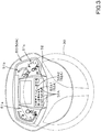
- a plurality of display devices 50 are provided around the operator seat 10.
- the plurality of display devices 50 include a first display device 50A provided in front of the operator seat 10 (the steering wheel 30) and include a second display device 50B provided on the side of the operator seat 10 (the steering wheel 30).
- the first display device 50A is a meter panel or the like configured to mainly display various information regarding the operation, and includes a prime mover tachometer 51a configured to display a revolving speed of the prime mover 4, a water temperature meter 51b, and a fuel gauge 51c.
- the first display device 50A has a notifier device 52 including a display lamp 52A that notifies various information by turning on / off the light.
- the first display device 50A shown in FIG. 3 is just an example, and is not limited to the configuration described above.
- the second display device 50B is a device configured to mainly display information regarding various operations, and is constituted of a touch panel or the like.
- Various types of menus are displayed on the second display device 50B, and the setting screen M1 is displayed by performing a predetermined operation as shown in FIG. 4 , and various types of settings of the tractor 1 can be performed on the setting screen M1.
- the tractor 1 includes a controller device 40.
- the controller device 40 performs various types of controls of the tractor 1.
- the controller device 40 is connected to an accelerator sensor 42a configured to detect an operation extent of an accelerator 41a, an ignition switch 42b, a one-touch switch 42c, a vehicle-speed detector sensor 42d configured to detect a vehicle speed (a speed), a braking-operation detector sensor 42e configured to detect the operation extent of a braking-operation member 31 (a brake pedal 31L and a brake pedal 31R), a clutch lever sensor 42f configured to detect the position of the clutch lever 32B, a clutch-operation detector sensor 42g configured to detect the operation extent of the clutch pedal 32A, a sitting detector sensor 42m, and the like.
- the sitting detector sensor 42m is a sensor configured to detect whether or not the operator is sitting on the operator seat 10.
- the controller device 40 changes the revolving speed of the prime mover 4 (referred to as a prime mover revolving speed) according to the operation extent.
- the controller 40 starts the prime mover 4 through a predetermined process when the ignition switch 42b is turned on, and stops the driving of the prime mover 4 when the ignition switch 42b is turned off.
- the controller device 40 controls the control valve to stretch the lift cylinder and thereby moves the working device upward.
- the controller device 40 shortens the lift cylinder and moves the working device downward.
- the controller device 40 performs the braking control based on values outputted from the braking-operation detector sensor 42e.
- the controller device 40 operates the left hydraulic operating portion 48a to perform the braking by the left braking device 46a.
- the controller device 40 operates the right hydraulic operating portion 48b to perform the braking by the right braking device 46b.
- the controller device 40 activates the left hydraulic operating portion 48a and the left hydraulic operating portion 48a, so that the left braking device 46a and the right braking device 46b perform the braking operation.
- the controller device 40 magnetizes the solenoid of the forward-traveling switching valve 26 to switch the traveling clutch 5d to the forward-traveling side.
- the controller device 40 magnetizes the solenoid of the reverse-traveling switching valve 27 to switch the traveling clutch 5d to the reverse-traveling side.
- the controller device 40 demagnetizes the solenoids of the forward-traveling switching valve 26 and the reverse-traveling switching valve 27, and thereby the traveling clutch 5d is in the disengaging state.
- the controller device 40 is capable of performing the auto switching control.
- the auto switching control is a control to switch the traveling clutch 5d from the engaging state to the disengaging state according to the operation of the braking-operation member 31 (the brake pedal 31L and the brake pedal 31R). That is, the auto switching control is for switching the traveling clutch 5d to the disengaged state with use of the braking-operation member 31 configured to perform the braking under the situation where the traveling clutch 5d is switched between the forward-traveling side and the reverse-traveling side.
- a switching member 43 for switching the auto switching control between being valid and being invalid is connected to the controller device 40.
- the switching member 43 includes a switch 44.
- the switch 44 is installed around the operator seat 10 and is capable of being turned ON / OFF. At least when the auto switching control is invalid, the switch 44 switches the auto switching control from being invalid to being valid by being turned from OFF to ON.
- the clutch pedal 32A is one of the switching members 43, and when at least the auto switching control is valid, the clutch pedal 32A is operated to switch the auto switching control from being valid to being invalid.
- Either one of the first display device 50A and the second display device 50B is capable of displaying whether the auto switching control is valid or invalid.
- the first indicator light 52A1 corresponding to the auto switching control is turned on when the auto switching control is valid, and the first indicator light 52A1 is turned off when the auto switching control is invalid.
- the display portion corresponding to the auto switching control is turned on when the auto switching control is valid, and is turned off when the auto switching control is invalid.
- the controller device 40 performs the first processing and the second processing as the auto switching control.
- the controller device 40 refers to the vehicle-speed detector sensor 42d when the braking-operation member 31 is operated, and the traveling clutch 5d is switched from the engaging state to the disengaging state when the vehicle speed of the traveling device detected by the vehicle-speed detector sensor 42d is less than the threshold value E1 (km/h).
- the braking-operation member 31 since the braking-operation member 31 is being operated, the braking by the left braking device 46a and the right braking device 46b is performed.
- the traveling clutch 5d is disengaged in accordance with the operation of the braking-operation member 31 and the braking is performed.
- the controller device 40 refers to the vehicle-speed detector sensor 42d when the braking-operation member 31 is operated, and does not switch the traveling clutch 5d from the engaging state to the disengaging state when the vehicle speed of the traveling device detected by the vehicle-speed detector sensor 42d is the threshold value E1 (km/h) or more. Also in the second processing, since the braking-operation member 31 is operated, the braking by the left braking device 46a and the right braking device 46b is performed.
- the traveling clutch 5d is held in the engaging state even when the braking-operation member 31 is operated, and the braking is performed.
- the threshold value E1 (km/h) is a relatively high speed and can be set to 15 km/h, for example.
- the traveling clutch 5d when the vehicle speed of the traveling device is high, the traveling clutch 5d is held in the engaging state to perform the braking even when the braking-operation member 31 is operated, and when the vehicle speed of the traveling device is low, the traveling clutch 5d is held in the disengaging state to perform the braking when the braking-operation member 31 is operated.
- the notifier device 52 When the first processing is performed, the notifier device 52 notifies that the first processing has been performed. For example, of the plurality of indicator lights 52A of the notifier device 52, the second indicator light 52A2 corresponding to the auto switching control is turned on when the first processing is performed, and is turned off when the first processing is not performed. Thus, since the first display device 50A has the first display lamp 52A1 and the second display lamp 52A2, it is possible to display the valid and the invalid of the auto switching control and to perform the display of the first processing.
- the controller device 40 judges whether or not to execute the first processing on the basis of the operation states of both of the brake pedal 31L and the brake pedal 31R. For example, the controller device 40 does not perform the first processing when any one of the brake pedal 31L and the brake pedal 31R is operated, and performs the first processing when both of the brake pedal 31L and the brake pedal 31R are operated.
- the controller device 40 may judge whether or not to execute the first processing on the basis of the operation extent W1 of each of the brake pedal 31L and the brake pedal 31R.
- the controller device 40 performs the first processing when the operation extent W1 of each of the brake pedal 31L and the brake pedal 31R, that is, the depression amount W1 of each of the brake pedal 31L and the brake pedal 31R is equal to or more than a threshold value E2 preliminarily determined.
- the controller device 40 does not execute the first processing when the operation extent (the depression amount) W1 is less than the threshold value E2.
- the second display device 50B is capable of setting the threshold value E1 of vehicle speed and setting the threshold value E2 of operation extent. As shown in FIG. 4 , when a predetermined operation is performed, the setting screen M1 is displayed on the second display device 50B.
- the second display device 50B displays the vehicle-speed input portion 100 on the setting screen M1.
- the vehicle-speed input portion 100 is a portion for inputting the threshold value E1 of vehicle speed (km/h), and has a button input portion 101, a slide input portion 102, and a numerical-value display portion 103.
- the button input portion 101 is a portion for inputting the threshold value E1 of vehicle speed through a pressing operation, and includes an increasing input portion 101a for increasing the threshold value E1 and includes a decreasing input portion 101b for decreasing the threshold value E1.
- the slide input portion 102 is a portion for inputting the threshold value E1 through a sliding operation, and includes a scale portion 102a and an index portion 102b.
- the scale portion 102a is a scale indicating the magnitude of the threshold value E1 (a vehicle speed), and is constituted of a plurality of vertical bars (gauges) arranged parallel in the lateral direction, for example.
- E1 a vehicle speed
- the index portion 102b is a portion that indicates the threshold value E1 with respect to the scale portion 102a, and is configured to move in the parallel direction of the vertical bars.
- the index portion 102b is configured to be moved along the scale portion 102a through a touching operation or the like.
- the index portion 102b moves in the scale portion 102a in association with the threshold value E1 inputted through the button input portion 101.
- the index portion 102b moves in the direction to increase along the scale portion 102a.
- the index portion 102b moves in the direction to decrease along the scale 102a.
- the numerical-value display portion 103 displays, as a numeric number, the threshold value E1 set through the button input portion 101 and the slide input portion 102.
- the lower limit value of the threshold value E1 is preliminarily set, and the threshold value E1 is not allowed to be lower than the lower limit value preliminarily determined.
- the lower limit value of the threshold value E1 is set to a value larger than an ultralow speed value such as 1 km/h.
- the second display device 50B displays the operation-extent input portion 110 on the setting screen M1.
- the operation-extent input portion 110 has a button input portion 111, a slide input portion 112, and a numerical-value display portion 113.
- the button input portion 111 is a portion for inputting the threshold value E2 through a pressing operation, and includes an increasing input portion 111a for increasing the threshold value E2 and a decreasing input portion 111b for decreasing the threshold value E2.
- the slide input portion 112 is a portion for inputting the threshold value E2 through a slide operation, and includes a scale portion 112a and an index portion 112b.
- the scale portion 112a is a scale indicating the magnitude of the threshold value E2 (a vehicle speed), and is constituted of a plurality of vertical bars (gauges) arranged parallel in the lateral direction, for example.
- E2 a vehicle speed
- the index portion 112b is a portion that indicates the threshold value E2 with respect to the scale portion 112a, and is configured to move in the parallel direction of the vertical bars.
- the index portion 112b is configured to be moved along the scale portion 112a through a touching operation or the like.
- the index portion 112b moves in the scale portion 112a in association with the threshold value E2 inputted through the button input portion 111.
- the index portion 112b moves in the direction to increase along the scale portion 112a.
- the threshold value E1 is decreased through the decreasing input portion 111b
- the index portion 112b moves in the direction to decrease along the scale 112a.
- the numerical-value display portion 113 displays, as a numeric number, the threshold value E2 set through the button input portion 111 and the slide input portion 112.
- FIG. 5A to FIG. 5C are views showing a flow of the auto switching control and the like executed by the controller device 40.
- the controller device 40 judges whether the auto switching control is valid under a situation where the clutch pedal 32A is not operated and the clutch lever 32B is switched to either the forward-traveling position (F) or the reverse-traveling position (R) (step S1).
- the controller device 40 judges whether the operation extent W1 of the brake pedal (the brake pedal 31L and the brake pedal 31R) is equal to or greater than the threshold value E2 (step S2).
- the controller device 40 judges whether the vehicle speed of the traveling device is less than the threshold value E1 (km/h) (step S3).
- step S3 Yes When the vehicle speed of the traveling device is less than the threshold value E1 (km/h) (step S3, Yes), the controller device 40 switches the traveling clutch 5d from the engaging state to the released state (step S4).
- step S3 the controller device 40 performs the first processing to switch the traveling clutch 5d from the forward traveling side or the reverse traveling side to the neutral state (step S4: the first processing).
- step S4 the first processing.
- the controller device 40 temporarily holds the position of the clutch lever 32B before performing the first processing (a position holding processing).
- the controller device 40 performs the second processing that does not perform the switching of the traveling clutch 5d (step S5).
- the controller device 40 After performing the first processing, the controller device 40 progresses to the post-disengaging processing shown in FIG. 5B to FIG. 5C . As shown in FIG. 5B , in the post-disengaging processing, the controller device 40 judges whether or not the operation extent W1 of the brake pedal has become less than the threshold value E2 (step S10: a brake pedal judgement). At the brake pedal judgment S 10, for example, after the first processing is executed under the state where the brake pedal is depressed (after step S4), the controller device 40 judges whether the depressing of the brake pedal is released, that is, whether the brake pedal is released.
- step S10 When the operation extent W1 of the brake pedal becomes less than the threshold value E2 due to the releasing of the brake pedal or the like (step S10, Yes), the controller device 40 performs a return processing S11 to return the traveling clutch 5d before performing the first processing.
- the controller device 40 In the return processing S11, when the clutch lever 32B is held at the forward-traveling position (F) in the position holding processing, the controller device 40 returns the traveling clutch 5d to the forward-traveling side, and when the clutch lever 32B is held at the reverse-traveling position (R) in the position holding processing, the controller device 40 returns the traveling clutch 5d to the reverse-traveling side.
- step S15 a clutch pedal judgment.
- the controller device 40 judges whether or not the clutch pedal 32A has been operated (step S15: a clutch pedal judgment).
- step S15 the controller device 40 judges whether or not the clutch pedal 32A is depressed after the first processing is executed under the state where the clutch pedal 32A is not depressed (after step S4).
- step S15 when the clutch pedal 32A changes from the releasing state to the depressing state (step S15, Yes), the controller device 40 holds the disengaging state of the traveling clutch 5d (step S16), and switches the auto switching control from being valid to being invalid. (step S17).
- FIG. 6A and FIG. 6B are views summarizing a relation between the validation/invalidation of auto switching control, the position of the clutch lever, the vehicle speed, the operation of the clutch pedal, the operation of the brake pedal, and the like.
- the state in which the clutch lever 32B is switched to either the forward-traveling position (F) or the reverse-traveling position (R) is referred to as a forward/reverse switching state.
- the OFF state of the clutch pedal represents that the operation extent of the clutch pedal 32A is less than a predetermined extent (less than a threshold value), and represents, for example, the releasing state.
- the ON state of the clutch pedal represents that the operation extent of the clutch pedal 32A is the predetermined amount or more (the threshold value or more), and represents, for example, the depressing state.
- the OFF state of the brake pedal represents that the operation extent W1 of the brake pedal is less than the threshold value E2, and represents, for example, the releasing state.
- the ON state of the brake pedal represents the operation where the operation extent W1 of the brake pedal is equal to or more than the threshold value E2, and represents, for example, the depressing state.
- the pre-status shows the state where the operation is first performed
- the post-status shows the state where the clutch pedal 32A, the brake pedal, and the like are operated after the pre-status.
- the "engaging” represents that the traveling clutch 5d is in the engaging state
- the “disengaging” represents that the traveling clutch 5d is in the disengaging state
- the “Hold disengaging” represents that the disengaging state is maintained even in the post-status when at least the traveling clutch 5d is in the disengaging state in the pre-status.
- “Hold engaging” represents that the traveling clutch 5d is held in the engaging state even in the post-status at least when the traveling clutch 5d is in the engaging state in the pre-state.
- “Hold valid” represents that the valid is maintained even in the post-status when the auto switching control is valid at least in the pre-status.
- Switch invalid represents that the auto switching control is switched from being valid to being invalid in the post-status when the auto switching control is valid at least in the pre-status.
- the ON state of the sitting detector sensor 42m represents that the sitting is detected.
- the OFF state represents that the sitting is not detected.
- the traveling clutch 5d is in the disengaging state.
- the first processing is performed in the case where the vehicle speed detected when the brake pedal is operated is less than the threshold value E1, and then the traveling clutch 5d can be disengaged.
- the controller device 40 After the first processing is performed, under the state where the sitting detector sensor 42m detects the sitting (ON) and then the sitting is no longer detected (OFF), the controller device 40 holds the traveling clutch 5d in the disengaged state (hold disengaging), resets of the position of the clutch lever 32B in the position holding process (initializing), and sets the traveling clutch to the neutral position (N). On the other hand, even when the brake pedal is operated and the sitting is detected by the sitting detector sensor 42m (ON) after the first processing is performed, the controller device 40 holds the traveling clutch 5d in the disengaging state (hold disengaging), resets the position of the clutch lever 32B in the position holding processing (initializing), and sets the traveling clutch to the neutral position (N).
- the traveling clutch 5d when the traveling clutch 5d is operated after the first processing (after the pre-status), the auto switching control is switched from being valid to being invalid (switch invalid).
- the traveling clutch 5d when a changeover switch (the switch SW) is turned off after the first processing, the traveling clutch 5d is held in the disengaging state (hold disengaging), resets the position of the clutch lever 32B in the position holding processing (initializing), and sets the traveling clutch to the neutral position (N).
- the working vehicle 1 includes: the traveling clutch 5d configured to be switched between: the engaging state allowing the power to be transmitted to the traveling device; and the disengaging state cutting the power to be transmitted to the traveling device; the braking devices to brake the traveling device according to the operation of the braking-operation member 31; the controller device 40 to perform: the braking control to perform the braking according to the operation of the braking-operation member 31; and the auto-switching control to switch the traveling clutch 5d from the engaging state to the disengaging state according to the operation of the braking-operation member 31; and the switching member 43 to switch the auto-switching control between to be valid and to be invalid.
- the traveling clutch 5d configured to be switched between: the engaging state allowing the power to be transmitted to the traveling device; and the disengaging state cutting the power to be transmitted to the traveling device
- the braking devices to brake the traveling device according to the operation of the braking-operation member 31
- the controller device 40 to perform: the braking control to perform the braking according to the operation of the braking
- the controller device 40 performs: the first processing to switch the traveling clutch 5d from the engaging state to the disengaging state when the braking-operation member 31 is operated in a case where the auto-switching control is valid and a vehicle sped of the traveling device is less than a threshold; and the second processing to prevent the traveling clutch 5d from being switched from the engaging state to the disengaging state even when the braking-operation member 31 is operated in a case where the vehicle speed of the traveling device is equal to or higher than the threshold. According to this, when the vehicle speed of the traveling device is less than the threshold value and the vehicle speed is relatively low, the traveling clutch 5d can be switched from being in the engaging state to being in the disengaged state by operating the braking-operation member 31.
- the traveling clutch 5d is engaged without being disengaged, so that, for example, the working vehicle 1 is capable of stopping smoothly due to the braking by mechanical resistance of the prime mover or the like and to the braking by the braking-operation member 31.
- the working vehicle 1 includes: the operator seat 10; and the sitting detector sensor 42m to detect whether to be sitting on the operator seat 10.
- the controller device 40 holds the traveling clutch 5d in the disengaging state when the sitting detector sensor 42m does not detect the sitting on the operator seat 10 after the first processing. According to this configuration, even when the operator leaves the operator seat 10, the disengaging state of the clutch device 5d can be maintained (held).
- the working vehicle 1 includes the notifier device 52 to notify that the first processing has been performed. According to this configuration, the operator can easily recognize that the traveling clutch 5d is automatically disengaged.
- the braking-operation member 31 includes: the plurality of operating portions to perform the operation of the braking-operation member 31.
- the controller device 40 performs the first processing when the plurality of operating portions perform the operation of the braking-operation member 31.
- the braking when the braking is performed through the operation of at least the plurality of operating portions, it is possible to perform the braking while setting the traveling clutch 5d to the disengaged state.
- the plurality of operation portions are the brake pedal 31L and the brake pedal 31R
- the braking can be performed while setting the traveling clutch 5d to the disengaged state only when both the brake pedal 31L and the brake pedal 31R are operated.
- the switching member 43 includes the clutch-switching member 32 to switch the traveling clutch 5d from the engaging state to the disengaging state.
- the controller device 40 switches the auto-switching control from being valid to being invalid when the clutch-switching member 32 is operated under the state where the auto-switching control is valid. According to this configuration, under the state where the traveling clutch 5d can be disengaged through the operation of the braking-operation member 31, it is possible to invalidate the auto switching control for disengaging the clutch 5d through the operation of the braking-operation member 31, only by operating the clutch-switching member 32 configured to disengage the traveling clutch 5d.
- the controller device 40 switches the auto-switching control from being valid to being invalid when the clutch-switching member 32 and the braking-operation member 31 are operated under the state where the auto-switching control is valid. According to this configuration, it is possible to easily invalidate the auto switching control through the operation of the clutch-switching member 32 while operating the braking-operation member 31.
- the controller device 40 judges whether to perform the first processing according to the operation extent of the braking-operation member 31.
- the first processing is not performed when the operation extent of the braking-operation member 31 is small, while the first processing can be operated when the operation extent of the braking-operation member 31 is large.
- the first processing can be performed or not performed depending on the state of working in the working vehicle 1.
- the working vehicle 1 includes the display device 50 to set the operation extent for determining to perform the first processing. According to this configuration, for example, the operator can easily set the operation extent for performing the first processing while watching the display device 50.
- the working vehicle 1 includes the display device 50 to set a threshold of the vehicle speed. According to this configuration, for example, the operator can easily set the threshold value of the vehicle speed as to whether or not to perform the first processing while watching the display device 50.
- the working vehicle 1 includes the display device 50 to display that the auto-switching control is valid or invalid and to display the first processing. According to this configuration, for example, the operator can easily recognize whether the auto switching control is valid or invalid, or whether the first processing is performed, by watching the state displayed on the display device 50.
Landscapes
- Engineering & Computer Science (AREA)
- Mechanical Engineering (AREA)
- Transportation (AREA)
- General Engineering & Computer Science (AREA)
- Chemical & Material Sciences (AREA)
- Combustion & Propulsion (AREA)
- Braking Elements And Transmission Devices (AREA)
- Hydraulic Clutches, Magnetic Clutches, Fluid Clutches, And Fluid Joints (AREA)
- Control Of Transmission Device (AREA)
Abstract
Description
- The present invention relates to a working vehicle.
-
Patent Documents Patent Document 1, the clutch for transmitting power to a crawler is disengaged by pressing down the brake. - In
Patent Document 2, a brake force sensor configured to detect an operation force of the brake is provided in a tractor employing a hydraulic clutch as a main clutch of a traveling-driving system, and an operating pressure of the main clutch is controlled based on the operation force of the brake. -
- [Patent Document 1]
US Patent Publication No. 5048655 - [Patent Document 2] Japanese Unexamined Patent Publication No.
2003-172379 - In
Patent Documents - Thus, in view of the above problems, the present invention intends to provide a working vehicle configured to stably stop regardless of a vehicle speed (a traveling speed).
- To solve the problem mentioned above, the present invention employs the following technical means.
- A working vehicle includes: a traveling clutch to be switched between: an engaging state allowing power to be transmitted to a traveling device; and a disengaging state cutting the power to be transmitted to a traveling device; a braking device to brake the traveling device according to operation of a braking-operation member; a controller device to perform: a braking control to perform the braking according to the operation of the braking-operation member; and an auto-switching control to switch the traveling clutch from the engaging state to the disengaging state according to the operation of the braking-operation member; and a switching member to switch the auto-switching control between to be valid and to be invalid, wherein the controller device performs: a first processing to switch the traveling clutch from the engaging state to the disengaging state when the braking-operation member is operated in a case where the auto-switching control is valid and a vehicle sped of the traveling device is less than a threshold; and a second processing to prevent the traveling clutch from being switched from the engaging state to the disengaging state even when the braking-operation member is operated in a case where the vehicle speed of the traveling device is equal to or higher than the threshold.
- The working vehicle includes: an operator seat; and a sitting detector sensor to detect whether to be sitting on the operator seat. The controller device holds the traveling clutch in the disengaging state when the sitting detector sensor does not detect the sitting on the operator seat after the first processing.
- The working vehicle includes a notifier device to notify that the first processing has been performed.
- The braking-operation member includes: a plurality of operating portions to perform the operation of the braking-operation member, and wherein the controller device performs the first processing when the plurality of operating portions perform the operation of the braking-operation member.
- The switching member includes a clutch-switching member to switch the traveling clutch from the engaging state to the disengaging state, and wherein the controller device switches the auto-switching control from being valid to being invalid when the clutch-switching member is operated under a state where the auto-switching control is valid.
- The controller device switches the auto-switching control from being valid to being invalid when the clutch-switching member and the braking-operation member are operated under the state where the auto-switching control.
- The controller device judges whether to perform the first processing according to an operation extent of the braking-operation member.
- The working vehicle includes a display device to set the operation extent for determining to perform the first processing.
- The working vehicle includes a display device to set a threshold of the vehicle speed.
- The working vehicle includes a display device to display that the auto-switching control is valid or invalid and to display the first processing.
- According to the present invention, it is possible to stop a working vehicle regardless of a vehicle speed (a traveling speed).
-
-
FIG. 1 is a view illustrating a configuration of a tractor and illustrating a control block diagram according to an embodiment of the present invention. -
FIG. 2 is a view illustrating a periphery of an operator seat according to the embodiment. -
FIG. 3 is a view illustrating a first display device according to the embodiment. -
FIG. 4 is a view illustrating an example of a setting screen according to the embodiment. -
FIG. 5A is a view illustrating a flow to perform a first processing and a second processing in an auto-switching control according to the embodiment. -
FIG. 5B is a view illustrating a flow provided when the brake pedal is operated after the first processing according to the embodiment. -
FIG. 5C is a view illustrating a flow provided when the clutch pedal is operated after the first processing according to the embodiment. -
FIG. 6A is a view illustrating a relation between a position of a clutch lever, a vehicle speed, an operation of the clutch pedal, an operation of the brake pedal, and the like under a state where the auto-switching control is invalid according to the embodiment. -
FIG. 6B is a view illustrating a relation between a position of a clutch lever, a vehicle speed, an operation of the clutch pedal, an operation of the brake pedal, and the like under a state where the auto-switching control is valid according to the embodiment. -
FIG. 7 is a whole view illustrating a tractor according to the embodiments. - Hereinafter, an embodiment of the present invention will be described with appropriate reference to the drawings.
-
FIG. 7 is a side view showing an embodiment of a workingvehicle 1, andFIG. 7 is a plan view showing the embodiment of theworking vehicle 1. In the embodiment, theworking vehicle 1 is a tractor. However, the workingvehicle 1 is not limited to the tractor, and may be an agricultural machine (an agricultural vehicle) such as a combine and a transplanter, or a construction machine (a construction vehicle) such as a loader working machine. - Hereinafter, in the following description, the front side of the operator sitting on a
operator seat 10 of the tractor (the working vehicle) 1 (a direction indicated by an arrowed line A1 inFIG. 7 ) is referred to as the front, the rear side of the operator (a direction indicated by an arrowed line A2 inFIG. 7 ) is referred to as the rear, the left side of the operator is referred to as the left, and the right side of the operator is referred to as the right. In addition, a horizontal direction, which is a direction orthogonal to the front-rear direction of theworking vehicle 1, will be described as a vehicle width direction. - As shown in
FIG. 7 , thetractor 1 includes avehicle body 3, aprime mover 4, and atransmission device 5. Thevehicle body 3 has atraveling device 7 and is configured to travel. Thetraveling device 7 is a device havingfront wheels 7F andrear wheels 7R. Thefront wheels 7F may be a tire type or a crawler type. In addition, therear wheels 7R may also be a tire type or a crawler type. - The
prime mover 4 is a diesel engine, an electric motor, or the like, and is constituted of a diesel engine in this embodiment. Thespeed change device 5 is configured to switch the propulsive force of thetraveling device 7 through speed changing, and is also configured to switch thetraveling device 7 between forward traveling and reverse traveling. Thevehicle body 3 is provided with anoperator seat 10. - A connecting portion is provided on the rear portion of the
vehicle body 3. A working device can be attached to and detached from the connecting portion. By connecting the working device to the connecting portion, the working device can be pulled by thevehicle body 3. The working device is a tiller device for the tilling, a fertilizer sprayer device for spraying fertilizer, a pesticide sprayer device for spraying pesticides, a harvester device for the harvesting, a mower device for mowing grass and the like, a tedder device for tedding grass and the like, a raking device for raking grass and the like, a baler device for baling grass and the like, or the like. - As shown in
FIG. 2 , asteering wheel 30 for steering thevehicle body 3, a braking-operation member 31, and a clutch-switchingmember 32 are provided around theoperator seat 10. The braking-operation member 31 includes a plurality of operating portions, for example, abrake pedal 31L provided on the left side and abrake pedal 31R provided on the right side. Thebrake pedal 31L and thebrake pedal 31R are swingably supported by thevehicle body 3, and are configured to be operated by an operator sitting on theoperator seat 10. - The clutch-switching
member 32 includes aclutch pedal 32A and aclutch lever 32B. Theclutch pedal 32A is swingably supported by thevehicle body 3, and is configured to be operated by the operator sitting on theoperator seat 10 in the manner same as those of thebrake pedal 31L and thebrake pedal 31R. Theclutch lever 32B is swingably supported in the vicinity of thesteering wheel 30, and is configured to be switched between a forward-traveling position (F), a reverse-traveling position (R), and a neutral position (N). - As shown in
FIG. 1 , thetransmission device 5 includes a main shaft (a propulsion shaft) 5a, amain transmission portion 5b, ansub-transmission portion 5c, a traveling clutch 5d, and a PTOpower transmission portion 5e. Thepropulsion shaft 5a is rotatably supported by the housing case (a mission case) of thetransmission device 5, and the power from the crankshaft of theprime mover 4 is transmitted to thepropulsion shaft 5a. Themain transmission portion 5b has a plurality of gears and a shifter configured to change the engaging of the gears. Themain transmission portion 5b appropriately changes the engaging (meshing) of the plurality of gears with the shifter, and thereby changes and outputs (shifts) the revolving inputted from thepropulsion shaft 5a. - The
sub-transmission portion 5c has a plurality of gears and a shifter configured to change the engaging of the gears. Thesub-transmission portion 5c appropriately changes the engaging (meshing) of the plurality of gears with the shifter, and thereby changes and outputs (shifts) the revolving inputted from themain transmission device 5b. - The traveling clutch 5d is a clutch configured to be switched between an engaging state for transmitting the power to the traveling device 7 (the
front wheels 7F and therear wheels 7R) and a disengaging state for disengaging the transmission of power to the travelingdevice 7. The traveling clutch 5d has ashuttle shaft 12 and a clutch-switchingportion 13. The power outputted from theprime mover 4 is transmitted to theshuttle shaft 12. The clutch-switchingportion 13 is a hydraulic clutch configured to be switched between a forward-traveling side, a reverse-traveling side, and a neutral side. - The clutch-switching
portion 13 is connected to a forward-travelingswitching valve 26 and a reverse-travelingswitching valve 27 that are connected through a fluid tube (not shown in the drawings) or the like. The forward-travelingswitching valve 26 and the reverse-travelingswitching valve 27 are constituted of, for example, two-position electromagnetic switching valves. When the solenoid of the forward-travelingswitching valve 26 is magnetized, the clutch-switchingportion 13 switches to the forward-traveling side, and when the solenoid of the reverse-travelingswitching valve 27 is magnetized, the clutch-switchingportion 13 switches to the reverse-traveling side. When each of the solenoids of the forward-travelingswitching valve 26 and the reverse-travelingswitching valve 27 is demagnetized, the clutch-switchingportion 13 switches to the neutral side. - The clutch-switching
member 32 is capable of switching the clutch-switchingportion 13. When theclutch lever 32B is in the forward-traveling position (F), the solenoid of the forward-travelingswitching valve 26 is magnetized, while the solenoid of the reverse-travelingswitching valve 27 remains demagnetized, and the clutch-switchingportion 13 is switched to the forward-traveling side. When theclutch lever 32B is in the reverse position (R), the solenoid of the reverse-travelingswitching valve 27 is magnetized, while the solenoid of the forward-travelingswitching valve 26 is kept being demagnetized, and the clutch-switchingportion 13 is switched to the reverse-traveling side. When theclutch lever 32B is in the neutral position (N), the demagnetization of the solenoids of the forward-travelingswitching valve 26 and the reverse-travelingswitching valve 27 is maintained, and the clutch-switchingportion 13 is switched to the neutral side. - When the
clutch pedal 32A is operated under the state where theclutch lever 32B is in the forward-traveling position (F) and the reverse-traveling position (R), one of the solenoids of the forward-travelingswitching valve 26 and the reverse-travelingswitching valve 27 is magnetized, and thus theclutch switching portion 13 is switched, to the neutral side, from the forward-traveling side or the reverse-traveling side. - The
shuttle shaft 12 is connected to thepropulsion shaft 5a. The power of thepropulsion shaft 5a is transmitted to themain transmission portion 5b and thesub transmission portion 5c, and the power outputted from thesub transmission portion 5c is transmitted to the rear-wheel differential device 20R. The rear-wheel differential device 20R rotatably supports arear axle 21R to which therear wheel 7R is attached. That is, the traveling clutch 5d is in the engaging state, and transmits the power to the traveling device 7 (thefront wheels 7F and therear wheels 7R) when the clutch-switchingportion 13 is switched to either the forward-traveling side or the reverse-traveling side. When the clutch-switchingportion 13 is switched to the neutral side, the traveling clutch 5d is in the disengaged state, and cuts the transmission of power to the travelingdevice 7. - The PTO
power transmission portion 5e has aPTO propulsion shaft 14 and a PTO clutch 15. ThePTO propulsion shaft 14 is rotatably supported and is configured to transmit the power supplied from thepropulsion shaft 5a. ThePTO propulsion shaft 14 is connected to thePTO shaft 16 through the gears or the like. The PTO clutch 15 is, for example, constituted of a hydraulic clutch or the like, and when engaged or disengaged, the hydraulic clutch switches between a state where the power of thepropulsion shaft 5a is transmitted to thePTO propulsion shaft 14 and a state where the power of thepropulsion shaft 5a is not transmitted to thePTO propulsion shaft 14. - As shown in
FIG. 1 , thetractor 1 includes a braking device. The braking device has aleft braking device 46a and aright braking device 46b. Theleft braking device 46a and theright braking device 46b are disc-type braking devices, and are configured to be switched between a braking state for performing the braking and a releasing state for releasing the braking. Theleft braking device 46a is provided on the left side of therear axle 21R, and theright braking device 46b is provided on the right side of therear axle 21R. When the operator who drives thetractor 1 operates (steps on) thebrake pedal 31L, theleft connecting member 47a connected to thebrake pedal 31L is moved in a direction for the braking, and theleft braking device 46a can be brought into the braking state. When the operator operates (steps on) thebrake pedal 31R, theright connecting member 47b connected to thebrake pedal 31R is moved in a direction for the braking, and theright braking device 46b can be brought into the braking state. - In addition, the left
hydraulic operating portion 48a, which is operated by the operation fluid, is connected to theleft connecting member 47a. Aleft brake valve 49a is connected to the lefthydraulic operating portion 48a through a fluid tube. Theleft connecting member 47a can be moved in a direction for the braking when the lefthydraulic operating portion 48a is operated with theleft braking valve 49a. In addition, the righthydraulic operating portion 48b, which is operated by the operation fluid, is connected to theright connecting member 47b. Aright brake valve 49b is connected to the righthydraulic operating portion 48b through a fluid tube. Theright connecting member 47b can be moved in a direction for the braking when the righthydraulic operating portion 48b is operated with theright braking valve 49b. - As described above, the
left braking device 46a and theright braking device 46b can independently bring the leftrear wheel 7R and the rightrear wheel 7R into the braking state through the operation of thebrake pedal 31L and thebrake pedal 31R. - As shown in
FIG. 1 , a plurality ofdisplay devices 50 are provided around theoperator seat 10. The plurality ofdisplay devices 50 include afirst display device 50A provided in front of the operator seat 10 (the steering wheel 30) and include a second display device 50B provided on the side of the operator seat 10 (the steering wheel 30). - As shown in
FIG. 3 , thefirst display device 50A is a meter panel or the like configured to mainly display various information regarding the operation, and includes aprime mover tachometer 51a configured to display a revolving speed of theprime mover 4, awater temperature meter 51b, and afuel gauge 51c. In addition, thefirst display device 50A has anotifier device 52 including adisplay lamp 52A that notifies various information by turning on / off the light. Thefirst display device 50A shown inFIG. 3 is just an example, and is not limited to the configuration described above. - Similar to the
first display device 50A, the second display device 50B is a device configured to mainly display information regarding various operations, and is constituted of a touch panel or the like. Various types of menus are displayed on the second display device 50B, and the setting screen M1 is displayed by performing a predetermined operation as shown inFIG. 4 , and various types of settings of thetractor 1 can be performed on the setting screen M1. - As shown in
FIG. 1 , thetractor 1 includes acontroller device 40. Thecontroller device 40 performs various types of controls of thetractor 1. Thecontroller device 40 is connected to anaccelerator sensor 42a configured to detect an operation extent of anaccelerator 41a, anignition switch 42b, a one-touch switch 42c, a vehicle-speed detector sensor 42d configured to detect a vehicle speed (a speed), a braking-operation detector sensor 42e configured to detect the operation extent of a braking-operation member 31 (abrake pedal 31L and abrake pedal 31R), aclutch lever sensor 42f configured to detect the position of theclutch lever 32B, a clutch-operation detector sensor 42g configured to detect the operation extent of theclutch pedal 32A, a sittingdetector sensor 42m, and the like. The sittingdetector sensor 42m is a sensor configured to detect whether or not the operator is sitting on theoperator seat 10. - When the operation extent of the
accelerator 41a is detected by theaccelerator sensor 42a, thecontroller device 40 changes the revolving speed of the prime mover 4 (referred to as a prime mover revolving speed) according to the operation extent. Thecontroller 40 starts theprime mover 4 through a predetermined process when theignition switch 42b is turned on, and stops the driving of theprime mover 4 when theignition switch 42b is turned off. - When the one-
touch switch 42c is operated in a direction of rising (the upward-moving side), thecontroller device 40 controls the control valve to stretch the lift cylinder and thereby moves the working device upward. In addition, when the one-touch switch 42c is operated in a direction of lowering (the downward-moving side), thecontroller device 40 shortens the lift cylinder and moves the working device downward. - The
controller device 40 performs the braking control based on values outputted from the braking-operation detector sensor 42e. In the braking control, when the operation of thebrake pedal 31L is detected by the braking-operation detector sensor 42e, thecontroller device 40 operates the lefthydraulic operating portion 48a to perform the braking by theleft braking device 46a. In addition, in the braking control, when the operation of thebrake pedal 31R is detected by the braking-operation detector sensor 42e, thecontroller device 40 operates the righthydraulic operating portion 48b to perform the braking by theright braking device 46b. In addition, in the braking control, when the operations of thebrake pedal 31L and thebrake pedal 31R are detected by the braking-operation detector sensor 42e, thecontroller device 40 activates the lefthydraulic operating portion 48a and the lefthydraulic operating portion 48a, so that theleft braking device 46a and theright braking device 46b perform the braking operation. - When the
clutch lever sensor 42f detects that theclutch lever 32B has been switched to the forward-traveling position (F), thecontroller device 40 magnetizes the solenoid of the forward-travelingswitching valve 26 to switch the traveling clutch 5d to the forward-traveling side. When theclutch lever sensor 42f detects that theclutch lever 32B has been switched to the reverse position (R), thecontroller device 40 magnetizes the solenoid of the reverse-travelingswitching valve 27 to switch the traveling clutch 5d to the reverse-traveling side. When theclutch lever sensor 42f detects that theclutch lever 32B has been switched to the neutral position (N), thecontroller device 40 demagnetizes the solenoids of the forward-travelingswitching valve 26 and the reverse-travelingswitching valve 27, and thereby the traveling clutch 5d is in the disengaging state. - The
controller device 40 is capable of performing the auto switching control. The auto switching control is a control to switch the traveling clutch 5d from the engaging state to the disengaging state according to the operation of the braking-operation member 31 (thebrake pedal 31L and thebrake pedal 31R). That is, the auto switching control is for switching the traveling clutch 5d to the disengaged state with use of the braking-operation member 31 configured to perform the braking under the situation where the traveling clutch 5d is switched between the forward-traveling side and the reverse-traveling side. - A switching
member 43 for switching the auto switching control between being valid and being invalid is connected to thecontroller device 40. The switchingmember 43 includes aswitch 44. Theswitch 44 is installed around theoperator seat 10 and is capable of being turned ON / OFF. At least when the auto switching control is invalid, theswitch 44 switches the auto switching control from being invalid to being valid by being turned from OFF to ON. Theclutch pedal 32A is one of the switchingmembers 43, and when at least the auto switching control is valid, theclutch pedal 32A is operated to switch the auto switching control from being valid to being invalid. - Either one of the
first display device 50A and the second display device 50B is capable of displaying whether the auto switching control is valid or invalid. For example as shown inFIG. 3 , of the plurality ofindicator lights 52A of thenotifier device 52, the first indicator light 52A1 corresponding to the auto switching control is turned on when the auto switching control is valid, and the first indicator light 52A1 is turned off when the auto switching control is invalid. Alternatively, on a predetermined screen of the second display device 50B, the display portion corresponding to the auto switching control is turned on when the auto switching control is valid, and is turned off when the auto switching control is invalid. - The
controller device 40 performs the first processing and the second processing as the auto switching control. In the first processing, thecontroller device 40 refers to the vehicle-speed detector sensor 42d when the braking-operation member 31 is operated, and the traveling clutch 5d is switched from the engaging state to the disengaging state when the vehicle speed of the traveling device detected by the vehicle-speed detector sensor 42d is less than the threshold value E1 (km/h). In addition, in the first processing, since the braking-operation member 31 is being operated, the braking by theleft braking device 46a and theright braking device 46b is performed. That is, in the first processing, when the vehicle speed detected when the braking-operation member 31 is operated is less than the threshold value E1 (km/h), the traveling clutch 5d is disengaged in accordance with the operation of the braking-operation member 31 and the braking is performed. - On the other hand, in the second processing, the
controller device 40 refers to the vehicle-speed detector sensor 42d when the braking-operation member 31 is operated, and does not switch the traveling clutch 5d from the engaging state to the disengaging state when the vehicle speed of the traveling device detected by the vehicle-speed detector sensor 42d is the threshold value E1 (km/h) or more. Also in the second processing, since the braking-operation member 31 is operated, the braking by theleft braking device 46a and theright braking device 46b is performed. That is, in the second processing, when the vehicle speed detected when the braking-operation member 31 is operated is equal to or higher than the threshold value E1 (km/h), the traveling clutch 5d is held in the engaging state even when the braking-operation member 31 is operated, and the braking is performed. The threshold value E1 (km/h) is a relatively high speed and can be set to 15 km/h, for example. - As described above, in the auto switching control, when the vehicle speed of the traveling device is high, the traveling clutch 5d is held in the engaging state to perform the braking even when the braking-
operation member 31 is operated, and when the vehicle speed of the traveling device is low, the traveling clutch 5d is held in the disengaging state to perform the braking when the braking-operation member 31 is operated. - When the first processing is performed, the
notifier device 52 notifies that the first processing has been performed. For example, of the plurality ofindicator lights 52A of thenotifier device 52, the second indicator light 52A2 corresponding to the auto switching control is turned on when the first processing is performed, and is turned off when the first processing is not performed. Thus, since thefirst display device 50A has the first display lamp 52A1 and the second display lamp 52A2, it is possible to display the valid and the invalid of the auto switching control and to perform the display of the first processing. - In addition, the
controller device 40 judges whether or not to execute the first processing on the basis of the operation states of both of thebrake pedal 31L and thebrake pedal 31R. For example, thecontroller device 40 does not perform the first processing when any one of thebrake pedal 31L and thebrake pedal 31R is operated, and performs the first processing when both of thebrake pedal 31L and thebrake pedal 31R are operated. - In addition, the
controller device 40 may judge whether or not to execute the first processing on the basis of the operation extent W1 of each of thebrake pedal 31L and thebrake pedal 31R. Thecontroller device 40 performs the first processing when the operation extent W1 of each of thebrake pedal 31L and thebrake pedal 31R, that is, the depression amount W1 of each of thebrake pedal 31L and thebrake pedal 31R is equal to or more than a threshold value E2 preliminarily determined. Thecontroller device 40 does not execute the first processing when the operation extent (the depression amount) W1 is less than the threshold value E2. - Now, the second display device 50B is capable of setting the threshold value E1 of vehicle speed and setting the threshold value E2 of operation extent. As shown in
FIG. 4 , when a predetermined operation is performed, the setting screen M1 is displayed on the second display device 50B. - The second display device 50B displays the vehicle-
speed input portion 100 on the setting screen M1. The vehicle-speed input portion 100 is a portion for inputting the threshold value E1 of vehicle speed (km/h), and has abutton input portion 101, a slide input portion 102, and a numerical-value display portion 103. Thebutton input portion 101 is a portion for inputting the threshold value E1 of vehicle speed through a pressing operation, and includes an increasinginput portion 101a for increasing the threshold value E1 and includes a decreasing input portion 101b for decreasing the threshold value E1. The slide input portion 102 is a portion for inputting the threshold value E1 through a sliding operation, and includes ascale portion 102a and an index portion 102b. - The
scale portion 102a is a scale indicating the magnitude of the threshold value E1 (a vehicle speed), and is constituted of a plurality of vertical bars (gauges) arranged parallel in the lateral direction, for example. In thescale portion 102a, one side of the vertical bars in the parallel direction, for example, the left side has the minimum value, and the other side in the parallel direction, for example, the right side has the maximum value. The index portion 102b is a portion that indicates the threshold value E1 with respect to thescale portion 102a, and is configured to move in the parallel direction of the vertical bars. The index portion 102b is configured to be moved along thescale portion 102a through a touching operation or the like. In addition, the index portion 102b moves in thescale portion 102a in association with the threshold value E1 inputted through thebutton input portion 101. For example, when the threshold value E1 is increased through the increasinginput portion 101a, the index portion 102b moves in the direction to increase along thescale portion 102a. In addition, when the threshold value E1 is decreased through the decreasing input portion 101b, the index portion 102b moves in the direction to decrease along thescale 102a. The numerical-value display portion 103 displays, as a numeric number, the threshold value E1 set through thebutton input portion 101 and the slide input portion 102. - In the vehicle-
speed input portion 100, the lower limit value of the threshold value E1 is preliminarily set, and the threshold value E1 is not allowed to be lower than the lower limit value preliminarily determined. For example, the lower limit value of the threshold value E1 is set to a value larger than an ultralow speed value such as 1 km/h. - The second display device 50B displays the operation-
extent input portion 110 on the setting screen M1. The operation-extent input portion 110 has abutton input portion 111, aslide input portion 112, and a numerical-value display portion 113. Thebutton input portion 111 is a portion for inputting the threshold value E2 through a pressing operation, and includes an increasing input portion 111a for increasing the threshold value E2 and a decreasinginput portion 111b for decreasing the threshold value E2. Theslide input portion 112 is a portion for inputting the threshold value E2 through a slide operation, and includes ascale portion 112a and anindex portion 112b. - The
scale portion 112a is a scale indicating the magnitude of the threshold value E2 (a vehicle speed), and is constituted of a plurality of vertical bars (gauges) arranged parallel in the lateral direction, for example. In thescale portion 112a, one side of the vertical bars in the parallel direction, for example, the left side has the minimum value, and the other side in the parallel direction, for example, the right side has the maximum value. Theindex portion 112b is a portion that indicates the threshold value E2 with respect to thescale portion 112a, and is configured to move in the parallel direction of the vertical bars. Theindex portion 112b is configured to be moved along thescale portion 112a through a touching operation or the like. In addition, theindex portion 112b moves in thescale portion 112a in association with the threshold value E2 inputted through thebutton input portion 111. For example, when the threshold value E2 is increased through the increasing input portion 111a, theindex portion 112b moves in the direction to increase along thescale portion 112a. In addition, when the threshold value E1 is decreased through the decreasinginput portion 111b, theindex portion 112b moves in the direction to decrease along thescale 112a. The numerical-value display portion 113 displays, as a numeric number, the threshold value E2 set through thebutton input portion 111 and theslide input portion 112. -
FIG. 5A to FIG. 5C are views showing a flow of the auto switching control and the like executed by thecontroller device 40. - As shown in
FIG. 5A , thecontroller device 40 judges whether the auto switching control is valid under a situation where theclutch pedal 32A is not operated and theclutch lever 32B is switched to either the forward-traveling position (F) or the reverse-traveling position (R) (step S1). When the auto switching control is valid (step S1, Yes), thecontroller device 40 judges whether the operation extent W1 of the brake pedal (thebrake pedal 31L and thebrake pedal 31R) is equal to or greater than the threshold value E2 (step S2). When the operation extent W1 is equal to or greater than the threshold value E2 (step S2, Yes), thecontroller device 40 judges whether the vehicle speed of the traveling device is less than the threshold value E1 (km/h) (step S3). When the vehicle speed of the traveling device is less than the threshold value E1 (km/h) (step S3, Yes), thecontroller device 40 switches the traveling clutch 5d from the engaging state to the released state (step S4). When the vehicle speed of the traveling device is less than the threshold value E1 (km/h) (step S3, Yes), thecontroller device 40 performs the first processing to switch the traveling clutch 5d from the forward traveling side or the reverse traveling side to the neutral state (step S4: the first processing). When the first processing is performed, thecontroller device 40 temporarily holds the position of theclutch lever 32B before performing the first processing (a position holding processing). When the vehicle speed of the traveling device is not less than the threshold value E1 (km/h) (step S3, No), thecontroller device 40 performs the second processing that does not perform the switching of the traveling clutch 5d (step S5). - After performing the first processing, the
controller device 40 progresses to the post-disengaging processing shown inFIG. 5B to FIG. 5C . As shown inFIG. 5B , in the post-disengaging processing, thecontroller device 40 judges whether or not the operation extent W1 of the brake pedal has become less than the threshold value E2 (step S10: a brake pedal judgement). At the brakepedal judgment S 10, for example, after the first processing is executed under the state where the brake pedal is depressed (after step S4), thecontroller device 40 judges whether the depressing of the brake pedal is released, that is, whether the brake pedal is released. When the operation extent W1 of the brake pedal becomes less than the threshold value E2 due to the releasing of the brake pedal or the like (step S10, Yes), thecontroller device 40 performs a return processing S11 to return the traveling clutch 5d before performing the first processing. In the return processing S11, when theclutch lever 32B is held at the forward-traveling position (F) in the position holding processing, thecontroller device 40 returns the traveling clutch 5d to the forward-traveling side, and when theclutch lever 32B is held at the reverse-traveling position (R) in the position holding processing, thecontroller device 40 returns the traveling clutch 5d to the reverse-traveling side. - As shown in
FIG. 5C , thecontroller device 40 judges whether or not theclutch pedal 32A has been operated (step S15: a clutch pedal judgment). In the clutch pedal judgment S15, for example, thecontroller device 40 judges whether or not theclutch pedal 32A is depressed after the first processing is executed under the state where theclutch pedal 32A is not depressed (after step S4). - In the clutch
pedal judgment S 15, when theclutch pedal 32A changes from the releasing state to the depressing state (step S15, Yes), thecontroller device 40 holds the disengaging state of the traveling clutch 5d (step S16), and switches the auto switching control from being valid to being invalid. (step S17). -
FIG. 6A andFIG. 6B are views summarizing a relation between the validation/invalidation of auto switching control, the position of the clutch lever, the vehicle speed, the operation of the clutch pedal, the operation of the brake pedal, and the like. - For convenience of the explanation, the state in which the
clutch lever 32B is switched to either the forward-traveling position (F) or the reverse-traveling position (R) is referred to as a forward/reverse switching state. In addition, the OFF state of the clutch pedal represents that the operation extent of theclutch pedal 32A is less than a predetermined extent (less than a threshold value), and represents, for example, the releasing state. The ON state of the clutch pedal represents that the operation extent of theclutch pedal 32A is the predetermined amount or more (the threshold value or more), and represents, for example, the depressing state. The OFF state of the brake pedal represents that the operation extent W1 of the brake pedal is less than the threshold value E2, and represents, for example, the releasing state. The ON state of the brake pedal represents the operation where the operation extent W1 of the brake pedal is equal to or more than the threshold value E2, and represents, for example, the depressing state. InFIG. 6B , the pre-status shows the state where the operation is first performed, and the post-status shows the state where theclutch pedal 32A, the brake pedal, and the like are operated after the pre-status. - In addition, in
FIGS. 6A and6B , the "engaging" represents that the traveling clutch 5d is in the engaging state, and the "disengaging" represents that the traveling clutch 5d is in the disengaging state. In addition, the "Hold disengaging" represents that the disengaging state is maintained even in the post-status when at least the traveling clutch 5d is in the disengaging state in the pre-status. In addition, "Hold engaging" represents that the traveling clutch 5d is held in the engaging state even in the post-status at least when the traveling clutch 5d is in the engaging state in the pre-state. "Hold valid" represents that the valid is maintained even in the post-status when the auto switching control is valid at least in the pre-status. "Switch invalid" represents that the auto switching control is switched from being valid to being invalid in the post-status when the auto switching control is valid at least in the pre-status. In addition, inFIG. 6B , the ON state of the sittingdetector sensor 42m represents that the sitting is detected. The OFF state represents that the sitting is not detected. - As shown in No. 1 to No. 8 of
FIG. 6A , when theclutch pedal 32A is operated during the forward/reverse switching state when the auto switching control is invalid, the traveling clutch 5d is switched to either the engaging state or the disengaging state regardless of the brake pedal. - As shown in No. 9 to No. 16 in
FIG. 6A , even when theclutch pedal 32A is operated under the state where the auto switching control is invalid and theclutch lever 32B is in the neutral position (N), the traveling clutch 5d is disengaged. - As shown in No. 17 of
FIG. 6B , when theclutch pedal 32A and the brake pedal are not operated during the forward/reverse switching state when the auto switching control is valid, the traveling clutch 5d is in the disengaging state. After that, as shown in No. 18, when the brake pedal is operated under the state where theclutch pedal 32A is not operated, the first processing is performed in the case where the vehicle speed detected when the brake pedal is operated is less than the threshold value E1, and then the traveling clutch 5d can be disengaged. After the first processing is performed, under the state where the sittingdetector sensor 42m detects the sitting (ON) and then the sitting is no longer detected (OFF), thecontroller device 40 holds the traveling clutch 5d in the disengaged state (hold disengaging), resets of the position of theclutch lever 32B in the position holding process (initializing), and sets the traveling clutch to the neutral position (N). On the other hand, even when the brake pedal is operated and the sitting is detected by the sittingdetector sensor 42m (ON) after the first processing is performed, thecontroller device 40 holds the traveling clutch 5d in the disengaging state (hold disengaging), resets the position of theclutch lever 32B in the position holding processing (initializing), and sets the traveling clutch to the neutral position (N). - In addition, as shown in No. 18, when the traveling clutch 5d is operated after the first processing (after the pre-status), the auto switching control is switched from being valid to being invalid (switch invalid). In addition, as shown in No. 18, when a changeover switch (the switch SW) is turned off after the first processing, the traveling clutch 5d is held in the disengaging state (hold disengaging), resets the position of the
clutch lever 32B in the position holding processing (initializing), and sets the traveling clutch to the neutral position (N). - As shown in No. 19, when the
clutch pedal 32A is operated without operating the brake pedal during the forward/reverse switching state under the state where the auto switching control is valid, the traveling clutch 5d is in the disengaging state. Then, as shown in No. 19, when both of theclutch pedal 32A and the brake pedal are operated, the auto switching control is switched from being valid to being invalid (switch invalid). - As shown in No. 21, when the
clutch pedal 32A and the brake pedal are not operated during the forward/reverse switching state under the state where the auto switching control is valid, the traveling clutch 5d is in the engaging state. Then, as shown in No. 21, when the brake pedal is operated under the state where theclutch pedal 32A is not operated, the second processing is executed under the auto switching control is switched from being valid to being invalid (switch invalid). - As shown in No. 22, when the vehicle speed detected when the brake pedal is operated is equal to or higher than the threshold value E1 during the forward/reverse switching state under the state where the auto switching control is valid, the second processing is performed, and thus the traveling clutch 5d is in the engaging state. In addition, as shown in No22, when the
clutch pedal 32A is operated after the second processing, the auto switching control is switched from being valid to being invalid (switch invalid). - As shown in No. 23, when the brake pedal is operated during the forward/reverse switching state under the state where the auto switching control is valid, the traveling clutch 5d is in the disengaging state. Then, as shown in No. 23, when the brake pedal is operated, the auto switching control is switched from being valid to being invalid (switch invalid).
- As shown in No. 25 to No. 32, under the state where the auto switching control is valid and the
clutch lever 32B is in the neutral position (N), the traveling clutch 5d is maintained in the disengaging state regardless of the operation of theclutch pedal 32A. Under the situation, as shown in No. 26 and No. 30, when theclutch pedal 32A is started to be operated under the state where theclutch pedal 32A is not operated, the auto switching control is switched from being valid to being invalid (switch invalid). In addition, as shown in No. 26 and No. 30, when the brake pedal is started to be operated under the state where theclutch pedal 32A is not operated, the auto switching control is switched from being valid to being invalid (switch invalid). - The working
vehicle 1 includes: the traveling clutch 5d configured to be switched between: the engaging state allowing the power to be transmitted to the traveling device; and the disengaging state cutting the power to be transmitted to the traveling device; the braking devices to brake the traveling device according to the operation of the braking-operation member 31; thecontroller device 40 to perform: the braking control to perform the braking according to the operation of the braking-operation member 31; and the auto-switching control to switch the traveling clutch 5d from the engaging state to the disengaging state according to the operation of the braking-operation member 31; and the switchingmember 43 to switch the auto-switching control between to be valid and to be invalid. Thecontroller device 40 performs: the first processing to switch the traveling clutch 5d from the engaging state to the disengaging state when the braking-operation member 31 is operated in a case where the auto-switching control is valid and a vehicle sped of the traveling device is less than a threshold; and the second processing to prevent the traveling clutch 5d from being switched from the engaging state to the disengaging state even when the braking-operation member 31 is operated in a case where the vehicle speed of the traveling device is equal to or higher than the threshold. According to this, when the vehicle speed of the traveling device is less than the threshold value and the vehicle speed is relatively low, the traveling clutch 5d can be switched from being in the engaging state to being in the disengaged state by operating the braking-operation member 31. In this manner, even when the traveling clutch 5d is not manually switched, the workingvehicle 1 can be stopped smoothly. In addition to this configuration, when the vehicle speed of the traveling device is equal to or higher than the threshold value and the vehicle speed is relatively high, the traveling clutch 5d is engaged without being disengaged, so that, for example, the workingvehicle 1 is capable of stopping smoothly due to the braking by mechanical resistance of the prime mover or the like and to the braking by the braking-operation member 31. - The working
vehicle 1 includes: theoperator seat 10; and the sittingdetector sensor 42m to detect whether to be sitting on theoperator seat 10. Thecontroller device 40 holds the traveling clutch 5d in the disengaging state when the sittingdetector sensor 42m does not detect the sitting on theoperator seat 10 after the first processing. According to this configuration, even when the operator leaves theoperator seat 10, the disengaging state of theclutch device 5d can be maintained (held). - The working
vehicle 1 includes thenotifier device 52 to notify that the first processing has been performed. According to this configuration, the operator can easily recognize that the traveling clutch 5d is automatically disengaged. - The braking-
operation member 31 includes: the plurality of operating portions to perform the operation of the braking-operation member 31. Thecontroller device 40 performs the first processing when the plurality of operating portions perform the operation of the braking-operation member 31. According to this configuration, when the braking is performed through the operation of at least the plurality of operating portions, it is possible to perform the braking while setting the traveling clutch 5d to the disengaged state. For example, when the plurality of operation portions are thebrake pedal 31L and thebrake pedal 31R, the braking can be performed while setting the traveling clutch 5d to the disengaged state only when both thebrake pedal 31L and thebrake pedal 31R are operated. - The switching
member 43 includes the clutch-switchingmember 32 to switch the traveling clutch 5d from the engaging state to the disengaging state. Thecontroller device 40 switches the auto-switching control from being valid to being invalid when the clutch-switchingmember 32 is operated under the state where the auto-switching control is valid. According to this configuration, under the state where the traveling clutch 5d can be disengaged through the operation of the braking-operation member 31, it is possible to invalidate the auto switching control for disengaging the clutch 5d through the operation of the braking-operation member 31, only by operating the clutch-switchingmember 32 configured to disengage the traveling clutch 5d. - The
controller device 40 switches the auto-switching control from being valid to being invalid when the clutch-switchingmember 32 and the braking-operation member 31 are operated under the state where the auto-switching control is valid. According to this configuration, it is possible to easily invalidate the auto switching control through the operation of the clutch-switchingmember 32 while operating the braking-operation member 31. - The
controller device 40 judges whether to perform the first processing according to the operation extent of the braking-operation member 31. According to this configuration, for example, the first processing is not performed when the operation extent of the braking-operation member 31 is small, while the first processing can be operated when the operation extent of the braking-operation member 31 is large. For example, the first processing can be performed or not performed depending on the state of working in the workingvehicle 1. - The working
vehicle 1 includes thedisplay device 50 to set the operation extent for determining to perform the first processing. According to this configuration, for example, the operator can easily set the operation extent for performing the first processing while watching thedisplay device 50. - The working
vehicle 1 includes thedisplay device 50 to set a threshold of the vehicle speed. According to this configuration, for example, the operator can easily set the threshold value of the vehicle speed as to whether or not to perform the first processing while watching thedisplay device 50. - The working
vehicle 1 includes thedisplay device 50 to display that the auto-switching control is valid or invalid and to display the first processing. According to this configuration, for example, the operator can easily recognize whether the auto switching control is valid or invalid, or whether the first processing is performed, by watching the state displayed on thedisplay device 50. - In the above description, the embodiment of the present invention has been explained. However, all the features of the embodiment disclosed in this application should be considered just as examples, and the embodiment does not restrict the present invention accordingly. A scope of the present invention is shown not in the above-described embodiment but in claims, and is intended to include all modifications within and equivalent to a scope of the claims.
-
- 1
- Working vehicle (Tractor)
- 2
- Working device
- 5d
- Traveling clutch
- 10
- Operator seat
- 31
- Braking-operation member
- 31L
- Brake pedal
- 31R
- Brake pedal
- 40
- Controller device
- 42m
- Sitting detector sensor
- 43
- Switching member
- 46a, 46b
- Braking device
- 50
- Display device
- 52
- Notifier device
Claims (10)
- A working vehicle comprising:a traveling clutch (5d) configured to be switched between:an engaging state allowing power to be transmitted to a traveling device (7); anda disengaging state cutting the power to be transmitted to the traveling device (7);a braking device (46a, 46b) configured to brake the traveling device (7) according to operation of a braking-operation member (31);a controller device (40) configured to perform:a braking control to perform the braking according to the operation of the braking-operation member (31); andan auto-switching control to switch the traveling clutch (5d) from the engaging state to the disengaging state according to the operation of the braking-operation member (31); anda switching member (43) configured to switch the auto-switching control between to be valid and to be invalid,wherein the controller device (40) is configured to perform:a first processing to switch the traveling clutch (5d) from the engaging state to the disengaging state when the braking-operation member (31) is operated in a case where the auto-switching control is valid and a vehicle sped of the traveling device (7) is less than a threshold; anda second processing to prevent the traveling clutch (5d) from being switched from the engaging state to the disengaging state even when the braking-operation member (31) is operated in a case where the vehicle speed of the traveling device (7) is equal to or higher than the threshold.
- The working vehicle according to claim 1, comprising:an operator seat (10); anda sitting detector sensor (42m) configured to detect whether an operator is sitting on the operator seat (10),wherein the controller device (40) is configured to hold the traveling clutch (5d) in the disengaging state when the sitting detector sensor (42m) does not detect that the operator is sitting on the operator seat (10) after the first processing.
- The working vehicle according to claim 1 or 2, comprising
a notifier device (52) configured to notify that the first processing has been performed. - The working vehicle according to any one of claims 1 to 3,
wherein the braking-operation member (31) includes:
a plurality of operating portions (31L, 31R) configured to perform the operation of the braking-operation member (31), and
wherein the controller device (40) is configured to perform the first processing when the plurality of operating portions (31L, 31R) perform the operation of the braking-operation member (31). - The working vehicle according to any one of claims 1 to 4,
wherein the switching member (43) includes
a clutch-switching member (32) configured to switch the traveling clutch (5d) from the engaging state to the disengaging state, and
wherein the controller device (40) is configured to switch the auto-switching control from being valid to being invalid when the clutch-switching member (32) is operated under a state where the auto-switching control is valid. - The working vehicle according to claim 5,
wherein the controller device (40) is configured to switch the auto-switching control from being valid to being invalid when the clutch-switching member (32) and the braking-operation member (31) are operated under the state where the auto-switching control is valid. - The working vehicle according to any one of claims 1 to 5,
wherein the controller device (40) is configured to judge whether to perform the first processing according to an operation extent of the braking-operation member (31). - The working vehicle according to claim 7, comprising
a display device (50) configured to set the operation extent for determining whether to perform the first processing. - The working vehicle according to any one of claims 1 to 8, comprising
a display device (50) configured to set a threshold of the vehicle speed. - The working vehicle according to any one of claims 1 to 9, comprising
a display device (50) configured to display that the auto-switching control is valid or invalid and to display the first processing.
Applications Claiming Priority (1)
| Application Number | Priority Date | Filing Date | Title |
|---|---|---|---|
| JP2019109100A JP7242435B2 (en) | 2019-06-11 | 2019-06-11 | work vehicle |
Publications (2)
| Publication Number | Publication Date |
|---|---|
| EP3750762A1 true EP3750762A1 (en) | 2020-12-16 |
| EP3750762B1 EP3750762B1 (en) | 2023-01-04 |
Family
ID=71096493
Family Applications (1)
| Application Number | Title | Priority Date | Filing Date |
|---|---|---|---|
| EP20179046.6A Active EP3750762B1 (en) | 2019-06-11 | 2020-06-09 | Working vehicle |
Country Status (3)
| Country | Link |
|---|---|
| US (1) | US11268614B2 (en) |
| EP (1) | EP3750762B1 (en) |
| JP (1) | JP7242435B2 (en) |
Families Citing this family (1)
| Publication number | Priority date | Publication date | Assignee | Title |
|---|---|---|---|---|
| EP4242495B1 (en) * | 2022-03-10 | 2025-03-26 | Kubota Corporation | Driving assistance system and method |
Citations (10)
| Publication number | Priority date | Publication date | Assignee | Title |
|---|---|---|---|---|
| US5048655A (en) | 1990-05-22 | 1991-09-17 | Deere & Company | Electric declutch mechanism for direct drive crawler |
| US5626536A (en) * | 1994-07-19 | 1997-05-06 | Toyota Jidosha Kabushiki Kaisha | Lock-up clutch slip control apparatus and engine fuel-cut control apparatus for motor vehicle |
| JP2003172379A (en) | 2001-12-10 | 2003-06-20 | Yanmar Agricult Equip Co Ltd | Tractor |
| JP2005299732A (en) * | 2004-04-07 | 2005-10-27 | Hitachi Constr Mach Co Ltd | Clutch control unit for working vehicle |
| EP1764253A1 (en) * | 2004-03-16 | 2007-03-21 | Yanmar Co., Ltd. | Transmission of work vehicle |
| EP2815938A1 (en) * | 2013-06-19 | 2014-12-24 | Iseki & Co., Ltd. | Tractor brake control apparatus |
| WO2015184132A1 (en) * | 2014-05-28 | 2015-12-03 | Cummins Inc. | Systems and methods for idle coasting management |
| JP2016070465A (en) * | 2014-10-01 | 2016-05-09 | マツダ株式会社 | Control device for vehicle drive unit |
| JP2016200274A (en) * | 2015-10-30 | 2016-12-01 | 井関農機株式会社 | Tractor |
| US9540004B2 (en) * | 2012-06-20 | 2017-01-10 | Toyota Jidosha Kabushiki Kaisha | Vehicle control system |
Family Cites Families (5)
| Publication number | Priority date | Publication date | Assignee | Title |
|---|---|---|---|---|
| JP4617996B2 (en) | 2005-05-13 | 2011-01-26 | 株式会社豊田自動織機 | Industrial vehicle |
| JP5705755B2 (en) * | 2012-01-19 | 2015-04-22 | 日立建機株式会社 | Hydraulic control device for work machine |
| DE112014006308T5 (en) * | 2014-01-31 | 2016-11-17 | Hitachi Automotive Systems, Ltd. | braking system |
| US9746070B2 (en) * | 2014-11-26 | 2017-08-29 | Polaris Industries Inc. | Electronic control of a transmission |
| JP6044668B2 (en) | 2015-04-09 | 2016-12-14 | 井関農機株式会社 | Tractor |
-
2019
- 2019-06-11 JP JP2019109100A patent/JP7242435B2/en active Active
-
2020
- 2020-06-05 US US16/893,491 patent/US11268614B2/en active Active
- 2020-06-09 EP EP20179046.6A patent/EP3750762B1/en active Active
Patent Citations (10)
| Publication number | Priority date | Publication date | Assignee | Title |
|---|---|---|---|---|
| US5048655A (en) | 1990-05-22 | 1991-09-17 | Deere & Company | Electric declutch mechanism for direct drive crawler |
| US5626536A (en) * | 1994-07-19 | 1997-05-06 | Toyota Jidosha Kabushiki Kaisha | Lock-up clutch slip control apparatus and engine fuel-cut control apparatus for motor vehicle |
| JP2003172379A (en) | 2001-12-10 | 2003-06-20 | Yanmar Agricult Equip Co Ltd | Tractor |
| EP1764253A1 (en) * | 2004-03-16 | 2007-03-21 | Yanmar Co., Ltd. | Transmission of work vehicle |
| JP2005299732A (en) * | 2004-04-07 | 2005-10-27 | Hitachi Constr Mach Co Ltd | Clutch control unit for working vehicle |
| US9540004B2 (en) * | 2012-06-20 | 2017-01-10 | Toyota Jidosha Kabushiki Kaisha | Vehicle control system |
| EP2815938A1 (en) * | 2013-06-19 | 2014-12-24 | Iseki & Co., Ltd. | Tractor brake control apparatus |
| WO2015184132A1 (en) * | 2014-05-28 | 2015-12-03 | Cummins Inc. | Systems and methods for idle coasting management |
| JP2016070465A (en) * | 2014-10-01 | 2016-05-09 | マツダ株式会社 | Control device for vehicle drive unit |
| JP2016200274A (en) * | 2015-10-30 | 2016-12-01 | 井関農機株式会社 | Tractor |
Also Published As
| Publication number | Publication date |
|---|---|
| JP7242435B2 (en) | 2023-03-20 |
| JP2020200903A (en) | 2020-12-17 |
| US11268614B2 (en) | 2022-03-08 |
| US20200393041A1 (en) | 2020-12-17 |
| EP3750762B1 (en) | 2023-01-04 |
Similar Documents
| Publication | Publication Date | Title |
|---|---|---|
| CN106414142B (en) | Working truck | |
| KR101032826B1 (en) | Powertrain | |
| US7458917B2 (en) | Work vehicle with a speed change device | |
| JP3783630B2 (en) | Work vehicle | |
| EP3750739B1 (en) | Working vehicle | |
| EP3375680B1 (en) | Work vehicle | |
| EP3750762B1 (en) | Working vehicle | |
| JP2005343187A (en) | Multipurpose work vehicle | |
| JP5742688B2 (en) | Work vehicle | |
| JP2019199952A (en) | Work vehicle | |
| JP2018071676A (en) | Work vehicle | |
| JP4479325B2 (en) | PTO control device for tractor | |
| JP4653725B2 (en) | Work vehicle | |
| EP4108950B1 (en) | Working vehicle and tractor | |
| JP2013014150A (en) | Working vehicle | |
| JP7527861B2 (en) | Work vehicles | |
| JP7001499B2 (en) | Work vehicle | |
| JP3680451B2 (en) | Automatic transmission control device for work vehicle | |
| JP4087994B2 (en) | Tractor | |
| JP7388515B2 (en) | work vehicle | |
| JP2021024330A (en) | Work vehicle | |
| JP6184359B2 (en) | Tractor | |
| JP2021008825A (en) | Work vehicle | |
| JP6985959B2 (en) | Work vehicle | |
| JP2008273311A (en) | Work vehicle |
Legal Events
| Date | Code | Title | Description |
|---|---|---|---|
| PUAI | Public reference made under article 153(3) epc to a published international application that has entered the european phase |
Free format text: ORIGINAL CODE: 0009012 |
|
| STAA | Information on the status of an ep patent application or granted ep patent |
Free format text: STATUS: REQUEST FOR EXAMINATION WAS MADE |
|
| 17P | Request for examination filed |
Effective date: 20200609 |
|
| AK | Designated contracting states |
Kind code of ref document: A1 Designated state(s): AL AT BE BG CH CY CZ DE DK EE ES FI FR GB GR HR HU IE IS IT LI LT LU LV MC MK MT NL NO PL PT RO RS SE SI SK SM TR |
|
| AX | Request for extension of the european patent |
Extension state: BA ME |
|
| GRAP | Despatch of communication of intention to grant a patent |
Free format text: ORIGINAL CODE: EPIDOSNIGR1 |
|
| STAA | Information on the status of an ep patent application or granted ep patent |
Free format text: STATUS: GRANT OF PATENT IS INTENDED |
|
| INTG | Intention to grant announced |
Effective date: 20220908 |
|
| GRAS | Grant fee paid |
Free format text: ORIGINAL CODE: EPIDOSNIGR3 |
|
| GRAA | (expected) grant |
Free format text: ORIGINAL CODE: 0009210 |
|
| STAA | Information on the status of an ep patent application or granted ep patent |
Free format text: STATUS: THE PATENT HAS BEEN GRANTED |
|
| AK | Designated contracting states |
Kind code of ref document: B1 Designated state(s): AL AT BE BG CH CY CZ DE DK EE ES FI FR GB GR HR HU IE IS IT LI LT LU LV MC MK MT NL NO PL PT RO RS SE SI SK SM TR |
|
| REG | Reference to a national code |
Ref country code: GB Ref legal event code: FG4D |
|
| REG | Reference to a national code |
Ref country code: CH Ref legal event code: EP |
|
| REG | Reference to a national code |
Ref country code: AT Ref legal event code: REF Ref document number: 1541735 Country of ref document: AT Kind code of ref document: T Effective date: 20230115 |
|
| REG | Reference to a national code |
Ref country code: DE Ref legal event code: R096 Ref document number: 602020007297 Country of ref document: DE |
|
| REG | Reference to a national code |
Ref country code: IE Ref legal event code: FG4D |
|
| REG | Reference to a national code |
Ref country code: LT Ref legal event code: MG9D |
|
| REG | Reference to a national code |
Ref country code: NL Ref legal event code: MP Effective date: 20230104 |
|
| REG | Reference to a national code |
Ref country code: AT Ref legal event code: MK05 Ref document number: 1541735 Country of ref document: AT Kind code of ref document: T Effective date: 20230104 |
|
| PG25 | Lapsed in a contracting state [announced via postgrant information from national office to epo] |
Ref country code: NL Free format text: LAPSE BECAUSE OF FAILURE TO SUBMIT A TRANSLATION OF THE DESCRIPTION OR TO PAY THE FEE WITHIN THE PRESCRIBED TIME-LIMIT Effective date: 20230104 |
|
| PG25 | Lapsed in a contracting state [announced via postgrant information from national office to epo] |
Ref country code: RS Free format text: LAPSE BECAUSE OF FAILURE TO SUBMIT A TRANSLATION OF THE DESCRIPTION OR TO PAY THE FEE WITHIN THE PRESCRIBED TIME-LIMIT Effective date: 20230104 Ref country code: PT Free format text: LAPSE BECAUSE OF FAILURE TO SUBMIT A TRANSLATION OF THE DESCRIPTION OR TO PAY THE FEE WITHIN THE PRESCRIBED TIME-LIMIT Effective date: 20230504 Ref country code: NO Free format text: LAPSE BECAUSE OF FAILURE TO SUBMIT A TRANSLATION OF THE DESCRIPTION OR TO PAY THE FEE WITHIN THE PRESCRIBED TIME-LIMIT Effective date: 20230404 Ref country code: LV Free format text: LAPSE BECAUSE OF FAILURE TO SUBMIT A TRANSLATION OF THE DESCRIPTION OR TO PAY THE FEE WITHIN THE PRESCRIBED TIME-LIMIT Effective date: 20230104 Ref country code: LT Free format text: LAPSE BECAUSE OF FAILURE TO SUBMIT A TRANSLATION OF THE DESCRIPTION OR TO PAY THE FEE WITHIN THE PRESCRIBED TIME-LIMIT Effective date: 20230104 Ref country code: HR Free format text: LAPSE BECAUSE OF FAILURE TO SUBMIT A TRANSLATION OF THE DESCRIPTION OR TO PAY THE FEE WITHIN THE PRESCRIBED TIME-LIMIT Effective date: 20230104 Ref country code: ES Free format text: LAPSE BECAUSE OF FAILURE TO SUBMIT A TRANSLATION OF THE DESCRIPTION OR TO PAY THE FEE WITHIN THE PRESCRIBED TIME-LIMIT Effective date: 20230104 Ref country code: AT Free format text: LAPSE BECAUSE OF FAILURE TO SUBMIT A TRANSLATION OF THE DESCRIPTION OR TO PAY THE FEE WITHIN THE PRESCRIBED TIME-LIMIT Effective date: 20230104 |
|
| PG25 | Lapsed in a contracting state [announced via postgrant information from national office to epo] |
Ref country code: SE Free format text: LAPSE BECAUSE OF FAILURE TO SUBMIT A TRANSLATION OF THE DESCRIPTION OR TO PAY THE FEE WITHIN THE PRESCRIBED TIME-LIMIT Effective date: 20230104 Ref country code: PL Free format text: LAPSE BECAUSE OF FAILURE TO SUBMIT A TRANSLATION OF THE DESCRIPTION OR TO PAY THE FEE WITHIN THE PRESCRIBED TIME-LIMIT Effective date: 20230104 Ref country code: IS Free format text: LAPSE BECAUSE OF FAILURE TO SUBMIT A TRANSLATION OF THE DESCRIPTION OR TO PAY THE FEE WITHIN THE PRESCRIBED TIME-LIMIT Effective date: 20230504 Ref country code: GR Free format text: LAPSE BECAUSE OF FAILURE TO SUBMIT A TRANSLATION OF THE DESCRIPTION OR TO PAY THE FEE WITHIN THE PRESCRIBED TIME-LIMIT Effective date: 20230405 Ref country code: FI Free format text: LAPSE BECAUSE OF FAILURE TO SUBMIT A TRANSLATION OF THE DESCRIPTION OR TO PAY THE FEE WITHIN THE PRESCRIBED TIME-LIMIT Effective date: 20230104 |
|
| REG | Reference to a national code |
Ref country code: DE Ref legal event code: R097 Ref document number: 602020007297 Country of ref document: DE |
|
| PG25 | Lapsed in a contracting state [announced via postgrant information from national office to epo] |
Ref country code: SM Free format text: LAPSE BECAUSE OF FAILURE TO SUBMIT A TRANSLATION OF THE DESCRIPTION OR TO PAY THE FEE WITHIN THE PRESCRIBED TIME-LIMIT Effective date: 20230104 Ref country code: RO Free format text: LAPSE BECAUSE OF FAILURE TO SUBMIT A TRANSLATION OF THE DESCRIPTION OR TO PAY THE FEE WITHIN THE PRESCRIBED TIME-LIMIT Effective date: 20230104 Ref country code: EE Free format text: LAPSE BECAUSE OF FAILURE TO SUBMIT A TRANSLATION OF THE DESCRIPTION OR TO PAY THE FEE WITHIN THE PRESCRIBED TIME-LIMIT Effective date: 20230104 Ref country code: DK Free format text: LAPSE BECAUSE OF FAILURE TO SUBMIT A TRANSLATION OF THE DESCRIPTION OR TO PAY THE FEE WITHIN THE PRESCRIBED TIME-LIMIT Effective date: 20230104 Ref country code: CZ Free format text: LAPSE BECAUSE OF FAILURE TO SUBMIT A TRANSLATION OF THE DESCRIPTION OR TO PAY THE FEE WITHIN THE PRESCRIBED TIME-LIMIT Effective date: 20230104 |
|
| PLBE | No opposition filed within time limit |
Free format text: ORIGINAL CODE: 0009261 |
|
| STAA | Information on the status of an ep patent application or granted ep patent |
Free format text: STATUS: NO OPPOSITION FILED WITHIN TIME LIMIT |
|
| PG25 | Lapsed in a contracting state [announced via postgrant information from national office to epo] |
Ref country code: SK Free format text: LAPSE BECAUSE OF FAILURE TO SUBMIT A TRANSLATION OF THE DESCRIPTION OR TO PAY THE FEE WITHIN THE PRESCRIBED TIME-LIMIT Effective date: 20230104 |
|
| 26N | No opposition filed |
Effective date: 20231005 |
|
| PG25 | Lapsed in a contracting state [announced via postgrant information from national office to epo] |
Ref country code: MC Free format text: LAPSE BECAUSE OF FAILURE TO SUBMIT A TRANSLATION OF THE DESCRIPTION OR TO PAY THE FEE WITHIN THE PRESCRIBED TIME-LIMIT Effective date: 20230104 |
|
| PG25 | Lapsed in a contracting state [announced via postgrant information from national office to epo] |
Ref country code: SI Free format text: LAPSE BECAUSE OF FAILURE TO SUBMIT A TRANSLATION OF THE DESCRIPTION OR TO PAY THE FEE WITHIN THE PRESCRIBED TIME-LIMIT Effective date: 20230104 Ref country code: MC Free format text: LAPSE BECAUSE OF FAILURE TO SUBMIT A TRANSLATION OF THE DESCRIPTION OR TO PAY THE FEE WITHIN THE PRESCRIBED TIME-LIMIT Effective date: 20230104 |
|
| REG | Reference to a national code |
Ref country code: CH Ref legal event code: PL |
|
| REG | Reference to a national code |
Ref country code: BE Ref legal event code: MM Effective date: 20230630 |
|
| PG25 | Lapsed in a contracting state [announced via postgrant information from national office to epo] |
Ref country code: LU Free format text: LAPSE BECAUSE OF NON-PAYMENT OF DUE FEES Effective date: 20230609 |
|
| REG | Reference to a national code |
Ref country code: IE Ref legal event code: MM4A |
|
| PG25 | Lapsed in a contracting state [announced via postgrant information from national office to epo] |
Ref country code: LU Free format text: LAPSE BECAUSE OF NON-PAYMENT OF DUE FEES Effective date: 20230609 |
|
| PG25 | Lapsed in a contracting state [announced via postgrant information from national office to epo] |
Ref country code: IE Free format text: LAPSE BECAUSE OF NON-PAYMENT OF DUE FEES Effective date: 20230609 |
|
| PG25 | Lapsed in a contracting state [announced via postgrant information from national office to epo] |
Ref country code: IE Free format text: LAPSE BECAUSE OF NON-PAYMENT OF DUE FEES Effective date: 20230609 Ref country code: CH Free format text: LAPSE BECAUSE OF NON-PAYMENT OF DUE FEES Effective date: 20230630 |
|
| PG25 | Lapsed in a contracting state [announced via postgrant information from national office to epo] |
Ref country code: IT Free format text: LAPSE BECAUSE OF FAILURE TO SUBMIT A TRANSLATION OF THE DESCRIPTION OR TO PAY THE FEE WITHIN THE PRESCRIBED TIME-LIMIT Effective date: 20230104 Ref country code: BE Free format text: LAPSE BECAUSE OF NON-PAYMENT OF DUE FEES Effective date: 20230630 |
|
| PG25 | Lapsed in a contracting state [announced via postgrant information from national office to epo] |
Ref country code: BG Free format text: LAPSE BECAUSE OF FAILURE TO SUBMIT A TRANSLATION OF THE DESCRIPTION OR TO PAY THE FEE WITHIN THE PRESCRIBED TIME-LIMIT Effective date: 20230104 |
|
| PG25 | Lapsed in a contracting state [announced via postgrant information from national office to epo] |
Ref country code: BG Free format text: LAPSE BECAUSE OF FAILURE TO SUBMIT A TRANSLATION OF THE DESCRIPTION OR TO PAY THE FEE WITHIN THE PRESCRIBED TIME-LIMIT Effective date: 20230104 |
|
| GBPC | Gb: european patent ceased through non-payment of renewal fee |
Effective date: 20240609 |
|
| PG25 | Lapsed in a contracting state [announced via postgrant information from national office to epo] |
Ref country code: GB Free format text: LAPSE BECAUSE OF NON-PAYMENT OF DUE FEES Effective date: 20240609 |
|
| PGFP | Annual fee paid to national office [announced via postgrant information from national office to epo] |
Ref country code: DE Payment date: 20250429 Year of fee payment: 6 |
|
| PGFP | Annual fee paid to national office [announced via postgrant information from national office to epo] |
Ref country code: FR Payment date: 20250508 Year of fee payment: 6 |
|
| PG25 | Lapsed in a contracting state [announced via postgrant information from national office to epo] |
Ref country code: CY Free format text: LAPSE BECAUSE OF FAILURE TO SUBMIT A TRANSLATION OF THE DESCRIPTION OR TO PAY THE FEE WITHIN THE PRESCRIBED TIME-LIMIT; INVALID AB INITIO Effective date: 20200609 |
|
| PG25 | Lapsed in a contracting state [announced via postgrant information from national office to epo] |
Ref country code: HU Free format text: LAPSE BECAUSE OF FAILURE TO SUBMIT A TRANSLATION OF THE DESCRIPTION OR TO PAY THE FEE WITHIN THE PRESCRIBED TIME-LIMIT; INVALID AB INITIO Effective date: 20200609 |
|
| PG25 | Lapsed in a contracting state [announced via postgrant information from national office to epo] |
Ref country code: TR Free format text: LAPSE BECAUSE OF FAILURE TO SUBMIT A TRANSLATION OF THE DESCRIPTION OR TO PAY THE FEE WITHIN THE PRESCRIBED TIME-LIMIT Effective date: 20230104 |