EP3750749A1 - Automated driving display system and vehicle communication system - Google Patents
Automated driving display system and vehicle communication system Download PDFInfo
- Publication number
- EP3750749A1 EP3750749A1 EP19751645.3A EP19751645A EP3750749A1 EP 3750749 A1 EP3750749 A1 EP 3750749A1 EP 19751645 A EP19751645 A EP 19751645A EP 3750749 A1 EP3750749 A1 EP 3750749A1
- Authority
- EP
- European Patent Office
- Prior art keywords
- vehicle
- lamp
- pedestrian
- light emitting
- probability
- Prior art date
- Legal status (The legal status is an assumption and is not a legal conclusion. Google has not performed a legal analysis and makes no representation as to the accuracy of the status listed.)
- Withdrawn
Links
Images





Classifications
-
- B—PERFORMING OPERATIONS; TRANSPORTING
- B60—VEHICLES IN GENERAL
- B60Q—ARRANGEMENT OF SIGNALLING OR LIGHTING DEVICES, THE MOUNTING OR SUPPORTING THEREOF OR CIRCUITS THEREFOR, FOR VEHICLES IN GENERAL
- B60Q1/00—Arrangement of optical signalling or lighting devices, the mounting or supporting thereof or circuits therefor
- B60Q1/02—Arrangement of optical signalling or lighting devices, the mounting or supporting thereof or circuits therefor the devices being primarily intended to illuminate the way ahead or to illuminate other areas of way or environments
- B60Q1/04—Arrangement of optical signalling or lighting devices, the mounting or supporting thereof or circuits therefor the devices being primarily intended to illuminate the way ahead or to illuminate other areas of way or environments the devices being headlights
- B60Q1/18—Arrangement of optical signalling or lighting devices, the mounting or supporting thereof or circuits therefor the devices being primarily intended to illuminate the way ahead or to illuminate other areas of way or environments the devices being headlights being additional front lights
-
- B—PERFORMING OPERATIONS; TRANSPORTING
- B60—VEHICLES IN GENERAL
- B60Q—ARRANGEMENT OF SIGNALLING OR LIGHTING DEVICES, THE MOUNTING OR SUPPORTING THEREOF OR CIRCUITS THEREFOR, FOR VEHICLES IN GENERAL
- B60Q1/00—Arrangement of optical signalling or lighting devices, the mounting or supporting thereof or circuits therefor
- B60Q1/26—Arrangement of optical signalling or lighting devices, the mounting or supporting thereof or circuits therefor the devices being primarily intended to indicate the vehicle, or parts thereof, or to give signals, to other traffic
- B60Q1/46—Arrangement of optical signalling or lighting devices, the mounting or supporting thereof or circuits therefor the devices being primarily intended to indicate the vehicle, or parts thereof, or to give signals, to other traffic for giving flashing caution signals during drive, other than signalling change of direction, e.g. flashing the headlights or hazard lights
-
- B—PERFORMING OPERATIONS; TRANSPORTING
- B60—VEHICLES IN GENERAL
- B60Q—ARRANGEMENT OF SIGNALLING OR LIGHTING DEVICES, THE MOUNTING OR SUPPORTING THEREOF OR CIRCUITS THEREFOR, FOR VEHICLES IN GENERAL
- B60Q1/00—Arrangement of optical signalling or lighting devices, the mounting or supporting thereof or circuits therefor
- B60Q1/26—Arrangement of optical signalling or lighting devices, the mounting or supporting thereof or circuits therefor the devices being primarily intended to indicate the vehicle, or parts thereof, or to give signals, to other traffic
- B60Q1/50—Arrangement of optical signalling or lighting devices, the mounting or supporting thereof or circuits therefor the devices being primarily intended to indicate the vehicle, or parts thereof, or to give signals, to other traffic for indicating other intentions or conditions, e.g. request for waiting or overtaking
- B60Q1/507—Arrangement of optical signalling or lighting devices, the mounting or supporting thereof or circuits therefor the devices being primarily intended to indicate the vehicle, or parts thereof, or to give signals, to other traffic for indicating other intentions or conditions, e.g. request for waiting or overtaking specific to autonomous vehicles
-
- B—PERFORMING OPERATIONS; TRANSPORTING
- B60—VEHICLES IN GENERAL
- B60Q—ARRANGEMENT OF SIGNALLING OR LIGHTING DEVICES, THE MOUNTING OR SUPPORTING THEREOF OR CIRCUITS THEREFOR, FOR VEHICLES IN GENERAL
- B60Q1/00—Arrangement of optical signalling or lighting devices, the mounting or supporting thereof or circuits therefor
- B60Q1/26—Arrangement of optical signalling or lighting devices, the mounting or supporting thereof or circuits therefor the devices being primarily intended to indicate the vehicle, or parts thereof, or to give signals, to other traffic
- B60Q1/50—Arrangement of optical signalling or lighting devices, the mounting or supporting thereof or circuits therefor the devices being primarily intended to indicate the vehicle, or parts thereof, or to give signals, to other traffic for indicating other intentions or conditions, e.g. request for waiting or overtaking
- B60Q1/543—Arrangement of optical signalling or lighting devices, the mounting or supporting thereof or circuits therefor the devices being primarily intended to indicate the vehicle, or parts thereof, or to give signals, to other traffic for indicating other intentions or conditions, e.g. request for waiting or overtaking for indicating other states or conditions of the vehicle
-
- F—MECHANICAL ENGINEERING; LIGHTING; HEATING; WEAPONS; BLASTING
- F21—LIGHTING
- F21V—FUNCTIONAL FEATURES OR DETAILS OF LIGHTING DEVICES OR SYSTEMS THEREOF; STRUCTURAL COMBINATIONS OF LIGHTING DEVICES WITH OTHER ARTICLES, NOT OTHERWISE PROVIDED FOR
- F21V23/00—Arrangement of electric circuit elements in or on lighting devices
-
- G—PHYSICS
- G07—CHECKING-DEVICES
- G07C—TIME OR ATTENDANCE REGISTERS; REGISTERING OR INDICATING THE WORKING OF MACHINES; GENERATING RANDOM NUMBERS; VOTING OR LOTTERY APPARATUS; ARRANGEMENTS, SYSTEMS OR APPARATUS FOR CHECKING NOT PROVIDED FOR ELSEWHERE
- G07C5/00—Registering or indicating the working of vehicles
- G07C5/02—Registering or indicating driving, working, idle, or waiting time only
- G07C5/06—Registering or indicating driving, working, idle, or waiting time only in graphical form
-
- G—PHYSICS
- G07—CHECKING-DEVICES
- G07C—TIME OR ATTENDANCE REGISTERS; REGISTERING OR INDICATING THE WORKING OF MACHINES; GENERATING RANDOM NUMBERS; VOTING OR LOTTERY APPARATUS; ARRANGEMENTS, SYSTEMS OR APPARATUS FOR CHECKING NOT PROVIDED FOR ELSEWHERE
- G07C5/00—Registering or indicating the working of vehicles
- G07C5/08—Registering or indicating performance data other than driving, working, idle, or waiting time, with or without registering driving, working, idle or waiting time
- G07C5/0816—Indicating performance data, e.g. occurrence of a malfunction
- G07C5/0825—Indicating performance data, e.g. occurrence of a malfunction using optical means
-
- H—ELECTRICITY
- H05—ELECTRIC TECHNIQUES NOT OTHERWISE PROVIDED FOR
- H05B—ELECTRIC HEATING; ELECTRIC LIGHT SOURCES NOT OTHERWISE PROVIDED FOR; CIRCUIT ARRANGEMENTS FOR ELECTRIC LIGHT SOURCES, IN GENERAL
- H05B47/00—Circuit arrangements for operating light sources in general, i.e. where the type of light source is not relevant
- H05B47/10—Controlling the light source
- H05B47/17—Operational modes, e.g. switching from manual to automatic mode or prohibiting specific operations
-
- B—PERFORMING OPERATIONS; TRANSPORTING
- B60—VEHICLES IN GENERAL
- B60Q—ARRANGEMENT OF SIGNALLING OR LIGHTING DEVICES, THE MOUNTING OR SUPPORTING THEREOF OR CIRCUITS THEREFOR, FOR VEHICLES IN GENERAL
- B60Q2300/00—Indexing codes for automatically adjustable headlamps or automatically dimmable headlamps
- B60Q2300/40—Indexing codes relating to other road users or special conditions
- B60Q2300/45—Special conditions, e.g. pedestrians, road signs or potential dangers
Definitions
- the present invention relates to an autonomous driving indication system for letting a pedestrian or another vehicle (hereinafter referred to as a pedestrian, etc.) clearly know that a vehicle is autonomously driven, and to a vehicle communication system for allowing a pedestrian who is about to cross a road to know that a vehicle being autonomously driven has detected the pedestrian.
- Challenging problems of autonomous driving under development include communication between a vehicle and a pedestrian, etc.
- technologies have been proposed to facilitate communication between an autonomous driving vehicle and a pedestrian, etc., by changing the flashing cycle, the light emitting area, the color of emitted light, the luminance, etc., of lamps depending on the driving state of the vehicle.
- Patent Literature 1 describes a technology wherein movable devices are mounted in vehicle lights, a pedestrian in the vicinity of a vehicle is detected with sensors, and the movable devices are turned to the pedestrian when the pedestrian comes close to the vehicle. This allows the pedestrian to know that the pedestrian has been detected by the vehicle, thus making the pedestrian in the vicinity of the autonomous driving vehicle feel safe.
- Patent Literature 2 proposes a technology for gradually changing the control voltages of the lamps with the passage of time so as to slowly flash the lamps.
- one object of the present invention is to provide an autonomous driving indication system that allows a pedestrian, etc., to clearly discriminate driving states of an autonomous driving vehicle and provide a vehicle communication system capable of predicting the behavior of a pedestrian and sending a more appropriate message to the pedestrian from the vehicle.
- an autonomous driving indication system of the present invention is characterized by comprising a lamp for indicating that a vehicle is autonomously driven, and a lamp ECU for flashing the lamp, wherein during flashing, the lamp ECU instantaneously changes the brightness of the lamp when the vehicle is driving and performs control to gradually change the brightness of the lamp with the passage of time while the vehicle is stationary.
- the lamp for indicating autonomous driving is not limited to any particular models or configurations, it is desirable that the lamp is composed of a plurality of light emitting segments from the viewpoint of enhancing its ability to communicate with a pedestrian, etc.
- the lamp ECU individually controls the flashing of the light emitting segments.
- the lamp ECU controls the flashing of the light emitting segments in unison as it is possible to more clearly indicate the stationary state.
- the lamp ECU performs control to cause the light emitting segments to flash in a different sequence during acceleration of the vehicle from during its deceleration. It should be noted that where the lamp is disposed may not be limited to any specific location; they may, for example, be disposed in a headlamp.
- a vehicle communication system of the present invention is characterized by comprising a lamp for indicating that a vehicle is autonomously driven, and a computing means for calculating the probability of a pedestrian in the vicinity of the vehicle crossing a road, and a control means for controlling light output of the lamp according to the calculated probability.
- the computing means can calculate the probability of the pedestrian crossing the road based on the information about behavior of the pedestrian received from sensors on board of the vehicle and a communication terminal carried by the pedestrian. Alternatively, it can also calculate the probability of the pedestrian crossing the road based on the information about the road conditions in the vicinity of the vehicle received from communication equipment provided in the road infrastructure.
- the lamp for indicating autonomous driving is not limited to any particular models or configurations, it is preferred that they are composed of a plurality of light emitting segments from the viewpoint of enhancing the ability to communicate with a pedestrian, etc., and that the control means is configured to individually control the flashing of the light emitting segments. More preferably, the lamp is disposed in a headlamp.
- the autonomous driving system of the present invention during flashing of the lamp, instantaneously changes the brightness of the lamp while the vehicle is driving, and performs control to gradually change the brightness of the lamp while the vehicle is stationary, a beneficial effect is provided that a pedestrian, etc., can clearly discriminate between driving state and stationary state of the autonomous driving vehicle. Moreover, as the autonomous driving system of the present invention controls the light output of the lamp according to the probability of a pedestrian crossing the road, a beneficial effect is provided that an appropriate message can be sent to the pedestrian from the vehicle.
- the vehicle 1 shown in FIG. 1 is provided with a pair of left and right headlamps 3 in the front of a vehicle body 2.
- a low beam lamp 4, a high beam lamp 5, a first communication lamp 6, and a second communication lamp 7 are provided in the housing (not shown) of each of the headlamps 3.
- the first and second communication lamps 6 and 7 function as lamps to indicate its driving state to a pedestrian, etc., by flashing.
- the first communication lamps 6 are each composed of three light emitting segments 6a-6c in a vertical configuration
- the second communication lamps 7 are each composed of six light emitting segments 7a-7f in a horizontal configuration.
- the first communication lamps 6 function as daytime running lamps and the second communication lamps 7 function as turn-signal lamps.
- a lamp ECU 8 for flashing four types of lamps 4, 5, 6, and 7 is disposed in the housing of the headlamp 3.
- the lamp ECU 8 comprises an autonomous driving indication system 21 together with the two types of communication lamps 6 and 7 and, when the autonomous driving mode is set for the vehicle 1, controls each light emitting segment of the communication lamps 6 and 7 in response to a command from a vehicle ECU 9.
- the lamp ECU 8 determines whether or not the autonomous driving mode is set (S31). If the autonomous driving mode is not set, manual drive lighting control is performed to flash the four types of lamps 4-7 in the same manner as during manual driving (S32). If the autonomous driving mode is set, it is determined whether or not the vehicle 1 is driving (S33) or stationary (S34) based on a command from the vehicle ECU 9.
- the lamp ECU 8 instantaneously changes the brightness (i.e., the driving voltages) of the light emitting segments as the first and/or second communication lamps 6, 7 flash (S35).
- gradual change control is performed to gradually change the brightness of the light emitting segments with the passage of time, as the first and/or second communication lamps 6, 7 flash (S36).
- FIGS. 5 and 6 show examples of control performed when the vehicle is driving.
- the three light emitting segments 6a-6c of the first communication lamps 6 are individually flashed with all the six light emitting segments 7a-7f of the second communication lamps 7 turned on.
- the acceleration/deceleration of the vehicle in autonomous driving is easily indicated to a pedestrian, etc., by performing gradual-change control on the brightness of the light emitting segments 6a-6c of the first communication lamps 6.
- the light emitting segments 6a, 6b, and 6c of each of the first communication lamps 6 in a fully turned-on condition are sequentially turned off from the top to the bottom to gradually reduce the light emitting area, and this gradual change operation is repeated to express the deceleration of the vehicle 1.
- the light emitting segments 6a, 6b, and 6c in a fully turned-off condition are sequentially turned on from the bottom to the top to gradually increase the light emitting area, and this gradual change control is repeated to express the acceleration of the vehicle 1.
- the light emitting segments 6a-6c of each of the first communication lamps 6 are sequentially flashed, one at a time, so as to slowly move the location of the segment turned on from the top to the bottom, and this gradual change control is repeated to express the deceleration of the vehicle 1.
- the location of the single segment turned on is slowly moved from the bottom to the top to express the acceleration of the vehicle 1.
- FIGS. 7 , 8 , and 9 show examples of control performed while the vehicle is stationary.
- the three light emitting segments of each first communication lamp 6 and the six light emitting segments of each second communication lamp 7 are all flashed in unison.
- the stationary state of the vehicle in autonomous driving is easily indicated to a pedestrian, etc., by changing the brightness of each light emitting segment with the passage of time.
- each light emitting segment of the second communication lamps 7 is flashed in unison while each light emitting segment of the first communication lamps 6 remains off.
- each light emitting segment of the second communication lamps 7 is flashed in unison while each light emitting segment of the first communication lamps 6 remains on. In both cases, while the second communication lamps 7 are flashed, the brightness of the light emitting segments thereof is controlled to gradually change.
- a lamp ECU 8 for causing the lamps 4, 5, 6, and 7 to flash is disposed in each headlamp 3.
- the lamp ECU 8 is electrically connected with the vehicle ECU 9 on the vehicle 2, and the vehicle ECU 9 is provided with a communication unit 10 and a probability computing unit 11. It should be noted that the communication unit 10 and the probability computing unit 11 may alternatively be disposed in the lamp ECU 8.
- the communication unit 10 obtains information about the behavior of a pedestrian and information about the road condition from the sensors on board of the own vehicle, communication equipment of the road infrastructure, GPS's, mobile radio terminals (none shown) of the pedestrian, etc.
- the probability computing unit 11 calculates, based on the information obtained by the communication unit 10, the probability that a pedestrian in the vicinity of the vehicle will cross the road. Further, the communication unit 10, the probability computing unit 11, and the lamp ECU 8 comprise the vehicle communication system 22.
- FIG. 11 shows the operation of the vehicle communication system 22.
- the vehicle ECU 8 determines whether or not the autonomous driving mode is set for the vehicle 1 (S31). If the autonomous driving mode is not set, manual drive lighting control is performed to flash each lamp 4-7 of the headlamps 3 in the same manner as during manual driving (S32). Once the autonomous driving mode is set, the communications lamps 6 and 7 are turned on to indicate that the vehicle 1 is autonomously driven (S33).
- the vehicle ECU 9 calculates, at the probability computing unit 11, the probability that the pedestrian will cross the road based on the information on the behavior of the pedestrian and the road condition (S35), and transmits the result of calculation to the lamp ECU 8. Then, serving as a means of control, the lamp ECU 8 controls the light output of the light emitting segments 6a-6c and 7a-7f of the communication lamps 6 and 7 individually or in unison according to the calculated probability (S36).
- the probability of the pedestrian crossing the road is evaluated comprehensively based on a plurality of factors and expressed in a numerical value.
- FIG. 12 illustrates several factors related to the behavior of a pedestrian and several factors related to the condition of the road.
- the former factors may include the orientation of the pedestrian, the direction in which the pedestrian is looking, an adult or child, and route information, etc.
- the latter factors may include a crosswalk, the time slot, the traffic volume, and the driving area, etc.
- the probability of the pedestrian crossing the road can be expressed in a high numerical value if the pedestrian is oriented toward the inside of the road; the probability of his/her crossing can be expressed in a low numerical value if the pedestrian is oriented toward the outside of the road; and the probability of his/her crossing can be expressed in an intermediate numerical value if the pedestrian is oriented toward or away from the vehicle.
- the probability can be expressed in a high numerical value if it is a signalized crosswalk; the probability of the pedestrian crossing the road can be expressed in a low numerical value if it is an unsignalized crosswalk; and the probability of the pedestrian crossing the road can be expressed in an intermediate numerical value if there is no crosswalk on the road.
- the probability of his/her crossing is evaluated as high if the destination information obtained from the pedestrian's wearable device includes a crossing route, and the probability is evaluated as low if the destination information does not include a route crossing the road.
- the time slot by considering the levels of difficulty of detecting the pedestrian with a vehicle-mounted sensor, the probability of his/her crossing is evaluated as high during the daytime, during which detection accuracy is high, and the probability is evaluated as low during the nighttime.
- the probability that the pedestrian will cross the road can be estimated more accurately by appropriately combining the evaluations of these plurality of factors expressed in numerical values.
- Examples of controlling the light output from the communication lamps 6 and 7 according to the probability of his/her crossing include a method shown in FIG. 13 .
- the brightness, frequency of flashing, flash timing, and number of segments turned on (light emitting area) are listed as the light output of the lamps 6 and 7, the luminescent color may also be included in addition to these.
- the lamps 6 and 7 may be controlled to be brighter as the probability becomes higher to more strongly call attention of the pedestrian, and the lamps 6 and 7 may be controlled to be dimmer as the probability becomes lower to call attention of the pedestrian less strongly.
- FIGS. 14-19 show more specific examples 1-6 of the control method.
- Example 1 As shown in FIG. 14(a) , if there is no pedestrian ahead of the vehicle 1, the light emitting segments of the communication lamps 6 and 7 of the left and right headlamps 3L and 3R are all turned on in unison to indicate that the vehicle 1 is autonomously driven. As shown in FIG. 14(b) , if there is a pedestrian P ahead of the vehicle 1 and to the left of the road, all the light emitting segments of the left headlamp 3L, which is on the side of the pedestrian, flash in a frequency corresponding to the probability that the pedestrian P will make a crossing, while all the light emitting segments of the right headlamp 3R are turned on.
- Example 2 as shown in FIG. 15(a) , if there is no pedestrian, the light emitting segments of the communication lamps 6 and 7 of the left and right headlamps 3L and 3R are all turned on to indicate that the vehicle 1 is autonomously driven. As shown in FIG. 15(b) , if there is a pedestrian P to the left of the road, the light emitting segments of the right headlamp 3R are all turned on while one or two of the light emitting segments of the left headlamp 3L, which are on the side of the pedestrian, flash in a frequency corresponding to the probability of his/her crossing and the location of the flashing segment(s) moves according to the change in the position of the pedestrian P as seen from the own vehicle 1.
- Example 3 as shown in FIG. 16(a) , if there is no pedestrian, the light emitting segments of the communication lamps 6 and 7 of the left and right headlamps 3L and 3R are all turned on to indicate that the vehicle 1 is autonomously driven. As shown in FIG. 16(b) , if there is a pedestrian P to the left of the road, all of the light emitting segments of the right headlamp 3R are turned on while one or two of the light emitting segments of the left headlamp 3L flash in a different color from that of the other segments and in a frequency corresponding to the probability of his/her crossing and the location of the segment(s) flashing in the different color than that of the other segments moves according to the change in the position of the pedestrian P.
- Example 4 as shown in FIG. 17(a) , if there is no pedestrian, the light emitting segments of the communication lamps 6 and 7 of the left and right headlamps 3L and 3R are all turned on to indicate that the vehicle 1 is autonomously driven. As shown in FIG. 17(b) , if there is a pedestrian P to the left of the road, all the light emitting segments of the right headlamp 3R are turned on while one or two of the light emitting segments of the left headlamp 3L turn on in a different color from the color indicative of the autonomous driving and in a frequency corresponding to the probability of his/her crossing and the location of the segment(s) turned on in the different color moves according to the change in the position of the pedestrian P.
- Example 5 as shown in FIG. 18(a) , if there is no pedestrian, the light emitting segments of the communication lamps 6 and 7 of the left and right headlamps 3L and 3R are all turned on to indicate that the vehicle 1 is autonomously driven. As shown in FIG. 18(b) , if there is a pedestrian P to the left of the road, all the light emitting segments of the right headlamp 3R are turned on while one, then two, and then three light emitting segments of the left headlamp 3L turn on at a cyclic speed corresponding to the probability of his/her crossing and the location of the segment(s) turned on moves according to the change in the position of the pedestrian P.
- Example 6 as shown in FIG. 19(a) , if there is no pedestrian, the light emitting segments of the communication lamps 6 and 7 of the left and right headlamps 3L and 3R are all turned on to indicate that the vehicle 1 is autonomously driven. As shown in FIG. 19(b) , if there is a pedestrian P to the left of the road, all the light emitting segments of the right headlamp 3R are turned on while one, then two, and then three light-emitting segments of the left headlamp 3L flash at a cyclic speed corresponding to the probability of his/her crossing, and the location of the flashing segment(s) moves according to the change in the position of the pedestrian P.
- the communication lamps 6 and 7 may be used to make that indication.
- the locations where the communication lamps are disposed are not limited to the headlamps 3; they may be disposed in side mirrors or in rear combination lamps. Alternatively, the communication lamps may be disposed on the vehicle as dedicated lamps.
- the present invention is not limited to the foregoing embodiments and can be carried out with the configuration of each part altered as required without departing from the spirit of the present invention.
- Vehicle body 3 Headlamp 6 First communication lamp, 6a-6c: light emitting segments 7 Second communication lamp, 7a-7f: light emitting segments 8 Lamp ECU 9 Vehicle ECU 10 Communication unit 11 Probability computing unit 21 Autonomous driving indication system 22 Vehicle communication system
Landscapes
- Engineering & Computer Science (AREA)
- Mechanical Engineering (AREA)
- Automation & Control Theory (AREA)
- Transportation (AREA)
- Physics & Mathematics (AREA)
- General Physics & Mathematics (AREA)
- General Engineering & Computer Science (AREA)
- Lighting Device Outwards From Vehicle And Optical Signal (AREA)
Abstract
Description
- The present invention relates to an autonomous driving indication system for letting a pedestrian or another vehicle (hereinafter referred to as a pedestrian, etc.) clearly know that a vehicle is autonomously driven, and to a vehicle communication system for allowing a pedestrian who is about to cross a road to know that a vehicle being autonomously driven has detected the pedestrian.
- Challenging problems of autonomous driving under development include communication between a vehicle and a pedestrian, etc. As such, conventionally, technologies have been proposed to facilitate communication between an autonomous driving vehicle and a pedestrian, etc., by changing the flashing cycle, the light emitting area, the color of emitted light, the luminance, etc., of lamps depending on the driving state of the vehicle.
- For example,
Patent Literature 1 describes a technology wherein movable devices are mounted in vehicle lights, a pedestrian in the vicinity of a vehicle is detected with sensors, and the movable devices are turned to the pedestrian when the pedestrian comes close to the vehicle. This allows the pedestrian to know that the pedestrian has been detected by the vehicle, thus making the pedestrian in the vicinity of the autonomous driving vehicle feel safe. Furthermore, in order to facilitate communication by means of light emitted from lamps, for example,Patent Literature 2 proposes a technology for gradually changing the control voltages of the lamps with the passage of time so as to slowly flash the lamps. -
- Patent Literature 1: Japanese Published Unexamined Patent Application No.
2015-174541 - Patent Literature 2: Japanese Published Unexamined Patent Application No.
2016-68707 - Indeed, a technique to slowly flash lamps easily catches a person's attention. However, if the lamps always flash in the same manner during autonomous driving, a pedestrian, etc., will not be able to determine the driving state of the vehicle based on the flashing of the lamps. As such, there is a problem that a pedestrian, etc., located away from and forward of the vehicle, for example, may not be able to tell from the flashing of the lamps whether the autonomous driving vehicle is driving or stationary.
- Moreover, it is difficult to accurately predict the behavior of a pedestrian standing on the roadside by using sensors. For example, it is not possible to accurately tell by using sensors whether the pedestrian is about to cross the road, continuing to move on along the sidewalk, or waiting there for another vehicle to arrive. As such, according to the prior art, there has been a problem that pedestrians not planning to make a crossing are irradiated and annoyed with the light from the movable lamps.
- Therefore, one object of the present invention is to provide an autonomous driving indication system that allows a pedestrian, etc., to clearly discriminate driving states of an autonomous driving vehicle and provide a vehicle communication system capable of predicting the behavior of a pedestrian and sending a more appropriate message to the pedestrian from the vehicle.
- In order to solve the above-described problem, an autonomous driving indication system of the present invention is characterized by comprising a lamp for indicating that a vehicle is autonomously driven, and a lamp ECU for flashing the lamp, wherein during flashing, the lamp ECU instantaneously changes the brightness of the lamp when the vehicle is driving and performs control to gradually change the brightness of the lamp with the passage of time while the vehicle is stationary.
- While the lamp for indicating autonomous driving is not limited to any particular models or configurations, it is desirable that the lamp is composed of a plurality of light emitting segments from the viewpoint of enhancing its ability to communicate with a pedestrian, etc.
- In this case, in order to let a pedestrian, etc., know of a change in the driving state, it is preferred that while the vehicle is driving, the lamp ECU individually controls the flashing of the light emitting segments. On the other hand, while the vehicle is stationary, it is preferred that the lamp ECU controls the flashing of the light emitting segments in unison as it is possible to more clearly indicate the stationary state.
- In particular, to allow a pedestrian, etc., to distinguish between acceleration and deceleration of the driving vehicle, it is preferred that the lamp ECU performs control to cause the light emitting segments to flash in a different sequence during acceleration of the vehicle from during its deceleration. It should be noted that where the lamp is disposed may not be limited to any specific location; they may, for example, be disposed in a headlamp.
- Furthermore, in order to solve the above-described problem, a vehicle communication system of the present invention is characterized by comprising a lamp for indicating that a vehicle is autonomously driven, and a computing means for calculating the probability of a pedestrian in the vicinity of the vehicle crossing a road, and a control means for controlling light output of the lamp according to the calculated probability.
- In this case, the computing means can calculate the probability of the pedestrian crossing the road based on the information about behavior of the pedestrian received from sensors on board of the vehicle and a communication terminal carried by the pedestrian. Alternatively, it can also calculate the probability of the pedestrian crossing the road based on the information about the road conditions in the vicinity of the vehicle received from communication equipment provided in the road infrastructure.
- Additionally, while the lamp for indicating autonomous driving is not limited to any particular models or configurations, it is preferred that they are composed of a plurality of light emitting segments from the viewpoint of enhancing the ability to communicate with a pedestrian, etc., and that the control means is configured to individually control the flashing of the light emitting segments. More preferably, the lamp is disposed in a headlamp.
- As the autonomous driving system of the present invention, during flashing of the lamp, instantaneously changes the brightness of the lamp while the vehicle is driving, and performs control to gradually change the brightness of the lamp while the vehicle is stationary, a beneficial effect is provided that a pedestrian, etc., can clearly discriminate between driving state and stationary state of the autonomous driving vehicle. Moreover, as the autonomous driving system of the present invention controls the light output of the lamp according to the probability of a pedestrian crossing the road, a beneficial effect is provided that an appropriate message can be sent to the pedestrian from the vehicle.
-
-
FIG. 1 is a front view of a vehicle showing one embodiment of the present invention. -
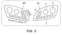
FIG. 2 is a front view of the headlamps showing the light emitting segments of the lamps. -
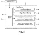
FIG. 3 is a block diagram showing an autonomous driving indication system. -
FIG. 4 is a flowchart showing the operation of the autonomous driving indication system. -
FIG. 5 is a front view of the headlamps, showing an example of a method for controlling the lamps during driving. -
FIG. 6 is a front view of the headlamps, showing another example of a method for controlling the lamps during driving. -
FIG. 7 is a front view of the headlamps, showing an example of a method for controlling the lamps while the vehicle is stationary. -
FIG. 8 is a front view of the headlamps, showing another example of a method for controlling the lamps while the vehicle is stationary. -
FIG. 9 is a front view of the headlamps, showing yet another example of a method for controlling the lamps while the vehicle is stationary. -
FIG. 10 is a block diagram showing the configuration of a vehicle communication system. -
FIG. 11 is a flowchart showing the operation of the communication system. -
FIG. 12 is an explanatory diagram showing how to determine the probability of a pedestrian crossing a road. -
FIG. 13 is an explanatory diagram showing a method of controlling the communication lamps. -
FIG. 14 is a schematic diagram showing pedestrian-vehicle communication of Example 1. -
FIG. 15 is a schematic diagram showing pedestrian-vehicle communication of Example 2. -
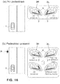
FIG. 16 is a schematic diagram showing pedestrian-vehicle communication of Example 3. -
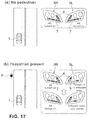
FIG. 17 is a schematic diagram showing pedestrian-vehicle communication of Example 4. -
FIG. 18 is a schematic diagram showing pedestrian-vehicle communication of Example 5. -
FIG. 19 is a schematic diagram showing pedestrian-vehicle communication of Example 6. - An embodiment of the present invention will be described hereinafter based on the drawings. The
vehicle 1 shown inFIG. 1 is provided with a pair of left andright headlamps 3 in the front of avehicle body 2. Alow beam lamp 4, ahigh beam lamp 5, afirst communication lamp 6, and asecond communication lamp 7 are provided in the housing (not shown) of each of theheadlamps 3. - When an autonomous driving mode is set for the
vehicle 1, the first andsecond communication lamps FIG. 2 , thefirst communication lamps 6 are each composed of threelight emitting segments 6a-6c in a vertical configuration, and thesecond communication lamps 7 are each composed of sixlight emitting segments 7a-7f in a horizontal configuration. - It should be noted that when a manual driving mode is set for the
vehicle 1, thefirst communication lamps 6 function as daytime running lamps and thesecond communication lamps 7 function as turn-signal lamps. - As shown in
FIG. 3 , alamp ECU 8 for flashing four types oflamps headlamp 3. Thelamp ECU 8 comprises an autonomous driving indication system 21 together with the two types ofcommunication lamps vehicle 1, controls each light emitting segment of thecommunication lamps vehicle ECU 9. - As shown in
FIG. 4 , initially, thelamp ECU 8 determines whether or not the autonomous driving mode is set (S31). If the autonomous driving mode is not set, manual drive lighting control is performed to flash the four types of lamps 4-7 in the same manner as during manual driving (S32). If the autonomous driving mode is set, it is determined whether or not thevehicle 1 is driving (S33) or stationary (S34) based on a command from thevehicle ECU 9. - If the
vehicle 1 is driving, thelamp ECU 8 instantaneously changes the brightness (i.e., the driving voltages) of the light emitting segments as the first and/orsecond communication lamps vehicle 1 is stationary, gradual change control is performed to gradually change the brightness of the light emitting segments with the passage of time, as the first and/orsecond communication lamps -
FIGS. 5 and6 show examples of control performed when the vehicle is driving. When the vehicle is driving, the three light emittingsegments 6a-6c of thefirst communication lamps 6 are individually flashed with all the six light emittingsegments 7a-7f of thesecond communication lamps 7 turned on. In particular, during flashing, the acceleration/deceleration of the vehicle in autonomous driving is easily indicated to a pedestrian, etc., by performing gradual-change control on the brightness of thelight emitting segments 6a-6c of thefirst communication lamps 6. - In the example of control shown in
FIG. 5 , during deceleration, thelight emitting segments first communication lamps 6 in a fully turned-on condition are sequentially turned off from the top to the bottom to gradually reduce the light emitting area, and this gradual change operation is repeated to express the deceleration of thevehicle 1. During acceleration, conversely, thelight emitting segments vehicle 1. - In the example of control shown in
FIG. 6 , during deceleration, thelight emitting segments 6a-6c of each of thefirst communication lamps 6 are sequentially flashed, one at a time, so as to slowly move the location of the segment turned on from the top to the bottom, and this gradual change control is repeated to express the deceleration of thevehicle 1. During acceleration, conversely, the location of the single segment turned on is slowly moved from the bottom to the top to express the acceleration of thevehicle 1. -
FIGS. 7 ,8 , and9 show examples of control performed while the vehicle is stationary. In the example of control shown inFIG. 7 , the three light emitting segments of eachfirst communication lamp 6 and the six light emitting segments of eachsecond communication lamp 7 are all flashed in unison. In particular, during flashing, the stationary state of the vehicle in autonomous driving is easily indicated to a pedestrian, etc., by changing the brightness of each light emitting segment with the passage of time. - In the example of control shown in
FIG. 8 , each light emitting segment of thesecond communication lamps 7 is flashed in unison while each light emitting segment of thefirst communication lamps 6 remains off. In the example of control shown inFIG. 9 , each light emitting segment of thesecond communication lamps 7 is flashed in unison while each light emitting segment of thefirst communication lamps 6 remains on. In both cases, while thesecond communication lamps 7 are flashed, the brightness of the light emitting segments thereof is controlled to gradually change. - The following describes a
vehicle communication system 22. As shown inFIG. 10 , alamp ECU 8 for causing thelamps headlamp 3. Thelamp ECU 8 is electrically connected with thevehicle ECU 9 on thevehicle 2, and thevehicle ECU 9 is provided with acommunication unit 10 and aprobability computing unit 11. It should be noted that thecommunication unit 10 and theprobability computing unit 11 may alternatively be disposed in thelamp ECU 8. - The
communication unit 10 obtains information about the behavior of a pedestrian and information about the road condition from the sensors on board of the own vehicle, communication equipment of the road infrastructure, GPS's, mobile radio terminals (none shown) of the pedestrian, etc. Theprobability computing unit 11 calculates, based on the information obtained by thecommunication unit 10, the probability that a pedestrian in the vicinity of the vehicle will cross the road. Further, thecommunication unit 10, theprobability computing unit 11, and thelamp ECU 8 comprise thevehicle communication system 22. -
FIG. 11 shows the operation of thevehicle communication system 22. Thevehicle ECU 8 determines whether or not the autonomous driving mode is set for the vehicle 1 (S31). If the autonomous driving mode is not set, manual drive lighting control is performed to flash each lamp 4-7 of theheadlamps 3 in the same manner as during manual driving (S32). Once the autonomous driving mode is set, thecommunications lamps vehicle 1 is autonomously driven (S33). - If a pedestrian is detected by a vehicle-mounted camera, etc., (S34), the
vehicle ECU 9 calculates, at theprobability computing unit 11, the probability that the pedestrian will cross the road based on the information on the behavior of the pedestrian and the road condition (S35), and transmits the result of calculation to thelamp ECU 8. Then, serving as a means of control, thelamp ECU 8 controls the light output of thelight emitting segments 6a-6c and 7a-7f of thecommunication lamps - Note that, preferably, the probability of the pedestrian crossing the road is evaluated comprehensively based on a plurality of factors and expressed in a numerical value.
FIG. 12 illustrates several factors related to the behavior of a pedestrian and several factors related to the condition of the road. The former factors may include the orientation of the pedestrian, the direction in which the pedestrian is looking, an adult or child, and route information, etc. The latter factors may include a crosswalk, the time slot, the traffic volume, and the driving area, etc. - For example, as for the orientation of the pedestrian, the probability of the pedestrian crossing the road can be expressed in a high numerical value if the pedestrian is oriented toward the inside of the road; the probability of his/her crossing can be expressed in a low numerical value if the pedestrian is oriented toward the outside of the road; and the probability of his/her crossing can be expressed in an intermediate numerical value if the pedestrian is oriented toward or away from the vehicle. As for the crosswalk, the probability can be expressed in a high numerical value if it is a signalized crosswalk; the probability of the pedestrian crossing the road can be expressed in a low numerical value if it is an unsignalized crosswalk; and the probability of the pedestrian crossing the road can be expressed in an intermediate numerical value if there is no crosswalk on the road.
- As for the route information, the probability of his/her crossing is evaluated as high if the destination information obtained from the pedestrian's wearable device includes a crossing route, and the probability is evaluated as low if the destination information does not include a route crossing the road. As for the time slot, by considering the levels of difficulty of detecting the pedestrian with a vehicle-mounted sensor, the probability of his/her crossing is evaluated as high during the daytime, during which detection accuracy is high, and the probability is evaluated as low during the nighttime. The probability that the pedestrian will cross the road can be estimated more accurately by appropriately combining the evaluations of these plurality of factors expressed in numerical values.
- Examples of controlling the light output from the
communication lamps FIG. 13 . In this case, although the brightness, frequency of flashing, flash timing, and number of segments turned on (light emitting area) are listed as the light output of thelamps lamps lamps FIGS. 14-19 show more specific examples 1-6 of the control method. - In Example 1, as shown in
FIG. 14(a) , if there is no pedestrian ahead of thevehicle 1, the light emitting segments of thecommunication lamps right headlamps vehicle 1 is autonomously driven. As shown inFIG. 14(b) , if there is a pedestrian P ahead of thevehicle 1 and to the left of the road, all the light emitting segments of theleft headlamp 3L, which is on the side of the pedestrian, flash in a frequency corresponding to the probability that the pedestrian P will make a crossing, while all the light emitting segments of theright headlamp 3R are turned on. - In Example 2, as shown in
FIG. 15(a) , if there is no pedestrian, the light emitting segments of thecommunication lamps right headlamps vehicle 1 is autonomously driven. As shown inFIG. 15(b) , if there is a pedestrian P to the left of the road, the light emitting segments of theright headlamp 3R are all turned on while one or two of the light emitting segments of theleft headlamp 3L, which are on the side of the pedestrian, flash in a frequency corresponding to the probability of his/her crossing and the location of the flashing segment(s) moves according to the change in the position of the pedestrian P as seen from theown vehicle 1. - In Example 3, as shown in
FIG. 16(a) , if there is no pedestrian, the light emitting segments of thecommunication lamps right headlamps vehicle 1 is autonomously driven. As shown inFIG. 16(b) , if there is a pedestrian P to the left of the road, all of the light emitting segments of theright headlamp 3R are turned on while one or two of the light emitting segments of theleft headlamp 3L flash in a different color from that of the other segments and in a frequency corresponding to the probability of his/her crossing and the location of the segment(s) flashing in the different color than that of the other segments moves according to the change in the position of the pedestrian P. - In Example 4, as shown in
FIG. 17(a) , if there is no pedestrian, the light emitting segments of thecommunication lamps right headlamps vehicle 1 is autonomously driven. As shown inFIG. 17(b) , if there is a pedestrian P to the left of the road, all the light emitting segments of theright headlamp 3R are turned on while one or two of the light emitting segments of theleft headlamp 3L turn on in a different color from the color indicative of the autonomous driving and in a frequency corresponding to the probability of his/her crossing and the location of the segment(s) turned on in the different color moves according to the change in the position of the pedestrian P. - In Example 5, as shown in
FIG. 18(a) , if there is no pedestrian, the light emitting segments of thecommunication lamps right headlamps vehicle 1 is autonomously driven. As shown inFIG. 18(b) , if there is a pedestrian P to the left of the road, all the light emitting segments of theright headlamp 3R are turned on while one, then two, and then three light emitting segments of theleft headlamp 3L turn on at a cyclic speed corresponding to the probability of his/her crossing and the location of the segment(s) turned on moves according to the change in the position of the pedestrian P. - In Example 6, as shown in
FIG. 19(a) , if there is no pedestrian, the light emitting segments of thecommunication lamps right headlamps vehicle 1 is autonomously driven. As shown inFIG. 19(b) , if there is a pedestrian P to the left of the road, all the light emitting segments of theright headlamp 3R are turned on while one, then two, and then three light-emitting segments of theleft headlamp 3L flash at a cyclic speed corresponding to the probability of his/her crossing, and the location of the flashing segment(s) moves according to the change in the position of the pedestrian P. - It should be noted that, while autonomous driving of the vehicle is indicated by the two types of
communication lamps headlamps 3; they may be disposed in side mirrors or in rear combination lamps. Alternatively, the communication lamps may be disposed on the vehicle as dedicated lamps. In addition, the present invention is not limited to the foregoing embodiments and can be carried out with the configuration of each part altered as required without departing from the spirit of the present invention. -
1 Vehicle 2 Vehicle body 3 Headlamp 6 First communication lamp, 6a-6c: light emitting segments 7 Second communication lamp, 7a-7f: light emitting segments 8 Lamp ECU 9 Vehicle ECU 10 Communication unit 11 Probability computing unit 21 Autonomous driving indication system 22 Vehicle communication system
Claims (10)
- An autonomous driving indication system characterized by comprising a lamp for indicating that a vehicle is autonomously driven, and a lamp ECU for flashing the lamp, wherein, during flashing, the lamp ECU instantaneously changes the brightness of the lamp while the vehicle is driving and performs control to gradually change the brightness of the lamp with the passage of time while the vehicle is stationary.
- The autonomous driving indication system according to claim 1, wherein the lamp is comprised of a plurality of light emitting segments.
- The autonomous driving indication system according to claim 2, wherein the lamp ECU individually flash the plurality of light emitting segments while the vehicle is driving and controls the brightness of the plurality of light emitting segments in unison while the vehicle is stationary.
- The autonomous driving indication system according to claim 3, wherein the lamp ECU causes the plurality of light emitting segments to flash in a different sequence during acceleration from during deceleration.
- The autonomous driving indication system according to any one of claims 1-4, wherein the lamp is disposed in a headlamp.
- A vehicle communication system characterized by comprising a lamp for indicating that a vehicle is autonomously driven, a computing means for calculating the probability of a pedestrian in the vicinity of the vehicle crossing a road, and a control means for controlling light output of the lamp according to the calculated probability.
- The vehicle communication system according to claim 6, wherein the computing means calculates the probability of the pedestrian crossing the road based on information about behavior of the pedestrian.
- The vehicle communication system according to claim 6, wherein the computing means calculates the probability of the pedestrian crossing the road based on information about conditions of the road in the vicinity of the vehicle.
- The vehicle communication system according to any one of claims 6-8, wherein the lamp is disposed in a headlamp.
- The vehicle communication system according to any one of claims 6-9, wherein the lamp is comprised of a plurality of light emitting segments, and the control means individually controls the flashing of each light emitting segment.
Applications Claiming Priority (3)
| Application Number | Priority Date | Filing Date | Title |
|---|---|---|---|
| JP2018020907 | 2018-02-08 | ||
| JP2018020933 | 2018-02-08 | ||
| PCT/JP2019/004190 WO2019156106A1 (en) | 2018-02-08 | 2019-02-06 | Automated driving display system and vehicle communication system |
Publications (2)
| Publication Number | Publication Date |
|---|---|
| EP3750749A1 true EP3750749A1 (en) | 2020-12-16 |
| EP3750749A4 EP3750749A4 (en) | 2021-10-27 |
Family
ID=67548935
Family Applications (1)
| Application Number | Title | Priority Date | Filing Date |
|---|---|---|---|
| EP19751645.3A Withdrawn EP3750749A4 (en) | 2018-02-08 | 2019-02-06 | AUTOMATED DRIVING DISPLAY SYSTEM AND VEHICLE COMMUNICATION SYSTEM |
Country Status (5)
| Country | Link |
|---|---|
| US (1) | US11678424B2 (en) |
| EP (1) | EP3750749A4 (en) |
| JP (1) | JP7217243B2 (en) |
| CN (1) | CN110126720A (en) |
| WO (1) | WO2019156106A1 (en) |
Families Citing this family (14)
| Publication number | Priority date | Publication date | Assignee | Title |
|---|---|---|---|---|
| EP3699812B1 (en) * | 2019-02-21 | 2025-03-05 | Polestar Performance AB | Method and system supporting obtaining of body parameters of a person outside a vehicle |
| CN110682859B (en) * | 2019-09-25 | 2021-05-28 | 恒大恒驰新能源汽车科技(广东)有限公司 | Driving mode prompting method, storage medium, electronic equipment and vehicle |
| JP2021049928A (en) * | 2019-09-26 | 2021-04-01 | 株式会社Subaru | Vehicle capable of automatic driving |
| JP2021049929A (en) * | 2019-09-26 | 2021-04-01 | 株式会社Subaru | Vehicle capable of automatic driving |
| JP2021054118A (en) * | 2019-09-27 | 2021-04-08 | 豊田合成株式会社 | vehicle |
| EP3800969A1 (en) * | 2019-10-02 | 2021-04-07 | Lumileds Holding B.V. | Lighting device and lighting system |
| JP7440237B2 (en) * | 2019-10-16 | 2024-02-28 | トヨタ自動車株式会社 | display device |
| CN111301276A (en) * | 2020-02-28 | 2020-06-19 | 华域视觉科技(上海)有限公司 | Multi-light-emitting-pattern signal display system and method and vehicle |
| WO2022030181A1 (en) * | 2020-08-05 | 2022-02-10 | 株式会社小糸製作所 | Vehicular projection device |
| JP7384123B2 (en) * | 2020-08-17 | 2023-11-21 | トヨタ自動車株式会社 | Vehicle lighting system |
| JP7505473B2 (en) * | 2021-11-18 | 2024-06-25 | トヨタ自動車株式会社 | Vehicle control device |
| JP2023140803A (en) * | 2022-03-23 | 2023-10-05 | トヨタ自動車株式会社 | Vehicle front structure |
| GB2620931B (en) * | 2022-07-25 | 2024-08-21 | Oxa Autonomy Ltd | System, autonomous vehicle, and method |
| CN115257521A (en) * | 2022-08-31 | 2022-11-01 | 长城汽车股份有限公司 | Vehicle lamp control method, vehicle lamp control device and vehicle |
Family Cites Families (22)
| Publication number | Priority date | Publication date | Assignee | Title |
|---|---|---|---|---|
| US5673050A (en) * | 1996-06-14 | 1997-09-30 | Moussally; George | Three-dimensional underground imaging radar system |
| JP4255906B2 (en) * | 2004-12-03 | 2009-04-22 | 富士通テン株式会社 | Driving assistance device |
| JP4661759B2 (en) * | 2006-10-06 | 2011-03-30 | 株式会社デンソー | Vehicle lighting control system |
| KR100824066B1 (en) * | 2007-04-13 | 2008-04-22 | 한국광기술원 | Communication device between vehicles and remote control method of vehicle using same |
| US7748127B1 (en) * | 2008-07-21 | 2010-07-06 | Harry Cosimano | Light fixture alignment tool |
| US8408765B2 (en) * | 2011-05-12 | 2013-04-02 | Delphi Technologies, Inc. | Light distribution pattern control using object detection and electrowetting lenses |
| EP2734995B1 (en) | 2011-07-27 | 2017-11-29 | Grote Industries, LLC | Method and system for flexible illuminated devices having edge lighting utilizing light active sheet material with integrated light emitting diode |
| KR101344847B1 (en) * | 2012-02-06 | 2013-12-24 | 이준석 | System for controlling a variable brake light using an user terminal and the controlling method thereof |
| CN102693637B (en) * | 2012-06-12 | 2014-09-03 | 北京联合大学 | Signal lamp for prompting right-turn vehicle to avoid pedestrians at crossroad |
| US9196164B1 (en) * | 2012-09-27 | 2015-11-24 | Google Inc. | Pedestrian notifications |
| CN202879668U (en) * | 2012-11-02 | 2013-04-17 | 侯红勋 | Bicycle control tail lamp |
| CN203543790U (en) * | 2013-10-15 | 2014-04-16 | 张华年 | Vehicle with safety indicating lamps |
| JP6137001B2 (en) * | 2014-03-14 | 2017-05-31 | 株式会社デンソー | In-vehicle device |
| JP6391347B2 (en) | 2014-07-29 | 2018-09-19 | 株式会社小糸製作所 | Vehicle display system |
| JP6336871B2 (en) | 2014-09-29 | 2018-06-06 | 株式会社小糸製作所 | Lighting circuit and vehicle lamp using the same |
| CN108349422A (en) | 2015-10-27 | 2018-07-31 | 株式会社小糸制作所 | Vehicle lighting device, vehicle system, and vehicle |
| US9788393B1 (en) * | 2016-03-18 | 2017-10-10 | International Business Machines Corporation | Light zones for smart lighting |
| JP7045993B2 (en) * | 2016-07-29 | 2022-04-01 | 株式会社小糸製作所 | Vehicle lighting systems, vehicle systems and vehicles |
| CN106218494B (en) * | 2016-08-29 | 2019-04-26 | 上海小糸车灯有限公司 | A kind of intelligent automotive light can be applied to spherical rubber-tyred autonomous driving vehicle |
| US10315563B1 (en) * | 2018-05-22 | 2019-06-11 | Zoox, Inc. | Acoustic notifications |
| US10723260B2 (en) * | 2018-09-25 | 2020-07-28 | Valeo North America, Inc. | Autonomous vehicle information lighting system |
| JP7212315B2 (en) * | 2019-05-09 | 2023-01-25 | トヨタ自動車株式会社 | vehicle headlight controller |
-
2019
- 2019-01-31 CN CN201910097567.8A patent/CN110126720A/en active Pending
- 2019-02-06 US US16/968,563 patent/US11678424B2/en active Active
- 2019-02-06 EP EP19751645.3A patent/EP3750749A4/en not_active Withdrawn
- 2019-02-06 WO PCT/JP2019/004190 patent/WO2019156106A1/en not_active Ceased
- 2019-02-06 JP JP2019570771A patent/JP7217243B2/en active Active
Also Published As
| Publication number | Publication date |
|---|---|
| JP7217243B2 (en) | 2023-02-02 |
| JPWO2019156106A1 (en) | 2021-01-28 |
| US20210043013A1 (en) | 2021-02-11 |
| CN110126720A (en) | 2019-08-16 |
| US11678424B2 (en) | 2023-06-13 |
| EP3750749A4 (en) | 2021-10-27 |
| WO2019156106A1 (en) | 2019-08-15 |
Similar Documents
| Publication | Publication Date | Title |
|---|---|---|
| US11678424B2 (en) | Autonomous driving indication system and vehicle communication system | |
| US11066009B2 (en) | Vehicular illumination device, vehicle system, and vehicle | |
| JP7222892B2 (en) | Vehicle lighting system, vehicle system and vehicle | |
| US11014575B2 (en) | Vehicular illumination device, vehicle system and vehicle | |
| CN108349430B (en) | Lighting device for vehicle, vehicle system, and vehicle | |
| US10759329B2 (en) | Out-of-vehicle notification device | |
| US20180312106A1 (en) | Vehicular illumination device | |
| US10529229B2 (en) | Traffic system linked illuminating vehicle assembly | |
| CN103917411B (en) | For the method and apparatus being grouped lighting unit | |
| KR101843326B1 (en) | U-turn signal Rear lamp and applying connectivity and autonomous driving technology combined with U-turn signal Rear lamp, method of the same | |
| CN110126719B (en) | Lighting system for vehicle and vehicle | |
| BR112018008276B1 (en) | vehicle notification device | |
| CN108482374A (en) | A kind of self-actuating brake method and its system based on signal lamp identification | |
| WO2017141395A1 (en) | Light distribution control device, light distribution control method, and light distribution control program | |
| EP4213112B1 (en) | Method and device for detecting a color of a traffic light in an environment of a vehicle | |
| CN210733969U (en) | Vehicle communication system | |
| JP2022147895A (en) | Speed reduction detection device | |
| KR101640895B1 (en) | Control method of street light | |
| JP2020087203A (en) | Collision detection system and collision detection method | |
| KR20170126771A (en) | Control method of street light | |
| JP7220099B2 (en) | vehicle lighting system | |
| KR101692217B1 (en) | How to control the street light | |
| US20250368127A1 (en) | Vehicle lighting system and method with display interaction information, and vehicle thereof | |
| CN113126634B (en) | Method and system for lighting by adopting unmanned aerial vehicle | |
| JP2025109713A (en) | Vehicle light module, lighting system, and vehicle |
Legal Events
| Date | Code | Title | Description |
|---|---|---|---|
| STAA | Information on the status of an ep patent application or granted ep patent |
Free format text: STATUS: THE INTERNATIONAL PUBLICATION HAS BEEN MADE |
|
| PUAI | Public reference made under article 153(3) epc to a published international application that has entered the european phase |
Free format text: ORIGINAL CODE: 0009012 |
|
| STAA | Information on the status of an ep patent application or granted ep patent |
Free format text: STATUS: REQUEST FOR EXAMINATION WAS MADE |
|
| 17P | Request for examination filed |
Effective date: 20200803 |
|
| AK | Designated contracting states |
Kind code of ref document: A1 Designated state(s): AL AT BE BG CH CY CZ DE DK EE ES FI FR GB GR HR HU IE IS IT LI LT LU LV MC MK MT NL NO PL PT RO RS SE SI SK SM TR |
|
| AX | Request for extension of the european patent |
Extension state: BA ME |
|
| DAV | Request for validation of the european patent (deleted) | ||
| DAX | Request for extension of the european patent (deleted) | ||
| A4 | Supplementary search report drawn up and despatched |
Effective date: 20210924 |
|
| RIC1 | Information provided on ipc code assigned before grant |
Ipc: H05B 47/17 20200101ALI20210920BHEP Ipc: F21V 23/00 20150101ALI20210920BHEP Ipc: B60Q 1/50 20060101ALI20210920BHEP Ipc: F21W 103/10 20180101AFI20210920BHEP |
|
| STAA | Information on the status of an ep patent application or granted ep patent |
Free format text: STATUS: THE APPLICATION IS DEEMED TO BE WITHDRAWN |
|
| 18D | Application deemed to be withdrawn |
Effective date: 20220423 |