EP3750739A1 - Working vehicle - Google Patents
Working vehicle Download PDFInfo
- Publication number
- EP3750739A1 EP3750739A1 EP20178821.3A EP20178821A EP3750739A1 EP 3750739 A1 EP3750739 A1 EP 3750739A1 EP 20178821 A EP20178821 A EP 20178821A EP 3750739 A1 EP3750739 A1 EP 3750739A1
- Authority
- EP
- European Patent Office
- Prior art keywords
- rate
- pto
- shaft
- control valve
- setting portion
- Prior art date
- Legal status (The legal status is an assumption and is not a legal conclusion. Google has not performed a legal analysis and makes no representation as to the accuracy of the status listed.)
- Granted
Links
Images




Classifications
-
- B—PERFORMING OPERATIONS; TRANSPORTING
- B60—VEHICLES IN GENERAL
- B60K—ARRANGEMENT OR MOUNTING OF PROPULSION UNITS OR OF TRANSMISSIONS IN VEHICLES; ARRANGEMENT OR MOUNTING OF PLURAL DIVERSE PRIME-MOVERS IN VEHICLES; AUXILIARY DRIVES FOR VEHICLES; INSTRUMENTATION OR DASHBOARDS FOR VEHICLES; ARRANGEMENTS IN CONNECTION WITH COOLING, AIR INTAKE, GAS EXHAUST OR FUEL SUPPLY OF PROPULSION UNITS IN VEHICLES
- B60K17/00—Arrangement or mounting of transmissions in vehicles
- B60K17/28—Arrangement or mounting of transmissions in vehicles characterised by arrangement, location, or type of power take-off
-
- B—PERFORMING OPERATIONS; TRANSPORTING
- B60—VEHICLES IN GENERAL
- B60K—ARRANGEMENT OR MOUNTING OF PROPULSION UNITS OR OF TRANSMISSIONS IN VEHICLES; ARRANGEMENT OR MOUNTING OF PLURAL DIVERSE PRIME-MOVERS IN VEHICLES; AUXILIARY DRIVES FOR VEHICLES; INSTRUMENTATION OR DASHBOARDS FOR VEHICLES; ARRANGEMENTS IN CONNECTION WITH COOLING, AIR INTAKE, GAS EXHAUST OR FUEL SUPPLY OF PROPULSION UNITS IN VEHICLES
- B60K17/00—Arrangement or mounting of transmissions in vehicles
- B60K17/02—Arrangement or mounting of transmissions in vehicles characterised by arrangement, location, or kind of clutch
-
- B—PERFORMING OPERATIONS; TRANSPORTING
- B60—VEHICLES IN GENERAL
- B60K—ARRANGEMENT OR MOUNTING OF PROPULSION UNITS OR OF TRANSMISSIONS IN VEHICLES; ARRANGEMENT OR MOUNTING OF PLURAL DIVERSE PRIME-MOVERS IN VEHICLES; AUXILIARY DRIVES FOR VEHICLES; INSTRUMENTATION OR DASHBOARDS FOR VEHICLES; ARRANGEMENTS IN CONNECTION WITH COOLING, AIR INTAKE, GAS EXHAUST OR FUEL SUPPLY OF PROPULSION UNITS IN VEHICLES
- B60K17/00—Arrangement or mounting of transmissions in vehicles
- B60K17/04—Arrangement or mounting of transmissions in vehicles characterised by arrangement, location or kind of gearing
- B60K17/10—Arrangement or mounting of transmissions in vehicles characterised by arrangement, location or kind of gearing of fluid gearing
-
- B—PERFORMING OPERATIONS; TRANSPORTING
- B60—VEHICLES IN GENERAL
- B60K—ARRANGEMENT OR MOUNTING OF PROPULSION UNITS OR OF TRANSMISSIONS IN VEHICLES; ARRANGEMENT OR MOUNTING OF PLURAL DIVERSE PRIME-MOVERS IN VEHICLES; AUXILIARY DRIVES FOR VEHICLES; INSTRUMENTATION OR DASHBOARDS FOR VEHICLES; ARRANGEMENTS IN CONNECTION WITH COOLING, AIR INTAKE, GAS EXHAUST OR FUEL SUPPLY OF PROPULSION UNITS IN VEHICLES
- B60K25/00—Auxiliary drives
- B60K25/06—Auxiliary drives from the transmission power take-off
-
- F—MECHANICAL ENGINEERING; LIGHTING; HEATING; WEAPONS; BLASTING
- F16—ENGINEERING ELEMENTS AND UNITS; GENERAL MEASURES FOR PRODUCING AND MAINTAINING EFFECTIVE FUNCTIONING OF MACHINES OR INSTALLATIONS; THERMAL INSULATION IN GENERAL
- F16D—COUPLINGS FOR TRANSMITTING ROTATION; CLUTCHES; BRAKES
- F16D67/00—Combinations of couplings and brakes; Combinations of clutches and brakes
- F16D67/02—Clutch-brake combinations
- F16D67/04—Clutch-brake combinations fluid actuated
-
- B—PERFORMING OPERATIONS; TRANSPORTING
- B60—VEHICLES IN GENERAL
- B60Y—INDEXING SCHEME RELATING TO ASPECTS CROSS-CUTTING VEHICLE TECHNOLOGY
- B60Y2200/00—Type of vehicle
- B60Y2200/20—Off-Road Vehicles
- B60Y2200/22—Agricultural vehicles
- B60Y2200/221—Tractors
-
- F—MECHANICAL ENGINEERING; LIGHTING; HEATING; WEAPONS; BLASTING
- F16—ENGINEERING ELEMENTS AND UNITS; GENERAL MEASURES FOR PRODUCING AND MAINTAINING EFFECTIVE FUNCTIONING OF MACHINES OR INSTALLATIONS; THERMAL INSULATION IN GENERAL
- F16D—COUPLINGS FOR TRANSMITTING ROTATION; CLUTCHES; BRAKES
- F16D2500/00—External control of clutches by electric or electronic means
- F16D2500/10—System to be controlled
- F16D2500/104—Clutch
- F16D2500/10406—Clutch position
- F16D2500/10437—Power Take Off clutch
Definitions
- the present invention relates to a working vehicle.
- Patent Document 1 Japanese Unexamined Patent Publication No. 2007-269061
- the working vehicle disclosed in Patent Document 1 Japanese Unexamined Patent Publication No. 2007-269061
- includes a PTO brake configured to brake the revolving of a PTO shaft in synchronization with a PTO clutch, and the PTO brake has a friction plate and a braking plate.
- Patent Document 1 Japanese Unexamined Patent Publication No. 2007-269061
- the present invention intends to provide a working vehicle configured to appropriately brake the PTO shaft depending on a type of working device.
- the present invention employs the following technical means.
- a working vehicle includes: a PTO shaft to transmit, to a working device, power of a propulsion shaft through which power of a prime mover is transmitted; a PTO clutch device having: a first rotor member to be rotated by the power of the propulsion shaft; a second rotor member to transmit the power to the PTO shaft; a pressing member to be moved by a pressure of operation fluid between a an engaging side on which the first rotor member is engaged with the second rotor member and a disengaging side on which the first rotor member is disengaged from the second rotor member; and a PTO brake to brake the PTO shaft when the pressing member is positioned on the disengaging side; a control valve to control the pressure of the operation fluid to be applied to the PTO clutch device; a rate-setting portion to set, with the control valve, a reducing rate at which the pressure of the operation fluid is reduced; and a controller device to control the control valve based on the reducing rate set by the rate-setting portion.
- the rate-setting portion is a rate-setting switch allowing an operator to manually set the reducing rate.
- the working vehicle mentioned above includes a revolving detector device to detect a revolving speed of the PTO shaft.
- the rate-setting portion sets the reducing rate based on the revolving speed of the PTO shaft, the revolving speed being detected by the revolving detector device when the pressing member is moved to the engaging side.
- the rate-setting portion sets the reducing rate based on a relation between the revolving speed of the PTO shaft and a control signal outputted to the control valve, the revolving speed and the control signal being provided at a timing when the pressing member is moved to the engaging side.
- the rate-setting portion lowers the reducing rate when an increasing rate of the revolving speed of the PTO shaft is smaller than a reference rate preliminarily determined and raises the reducing rate when the increasing rate is larger than the reference rate, with respect to an electric current value outputted as the control signal to the control valve.
- the rate-setting portion has a display device configured to allow to set sensitivity of the reducing rate.
- FIG. 8 is a side view showing a working vehicle 1 according to a first embodiment of the present invention.
- FIG. 8 is a plan view showing the working vehicle 1 according to the embodiment.
- the working vehicle 1 is a tractor.
- the working vehicle 1 is not limited to the tractor, and may be an agricultural machine (an agricultural vehicle) such as a combine harvester or a transplanter.
- a front side of an operator sitting on an operator seat 10 of the tractor (the working vehicle) 1 is referred to as the front
- a rear side of the operator is referred to as the rear
- a left side of the operator is referred to as the left
- a right side of the operator is referred to as the right.
- a horizontal direction that is a direction orthogonal to the front-rear direction of the working vehicle 1 will be described as a machine width direction.
- the tractor 1 includes a vehicle body 3 having a traveling device 7, a prime mover 4, a transmission device 5, and a steering device 11.
- the traveling device 7 is a device having a front wheel 7F and a rear wheel 7R.
- the front wheel 7F may be a tire type or a crawler type.
- the rear wheel 7R may also be a tire type or a crawler type.
- the prime mover 4 is an internal combustion engine such as a gasoline engine or a diesel engine, an electric motor, or the like. In this embodiment, the prime mover 4 is a diesel engine.
- the transmission device 5 is configured to switch the propulsive force of the traveling device 7 by shifting speeds and to switch between the forward traveling and the reverse traveling of the traveling device 7.
- a cabin 9 is provided in the vehicle body 3, and an operator seat 10 is provided in the cabin 9.
- An lifting device 8 is provided at the rear portion of the vehicle body 3.
- the working device 2 can be attached to and detached from the lifting device 8.
- the lifting device 8 is configured to lift the attached working device 2.
- the working device 2 is a tiller device for the tilling, a fertilizer sprayer device for spraying fertilizer, a pesticide sprayer device for spraying pesticides, a harvester device for the harvesting, a mower device for mowing grass and the like, a tedder device for tedding grass and the like, a raking device for raking grass and the like, a baler device for baling grass and the like, or the like.
- FIG. 8 an example in which attached the tiller device is attached as the working device 2 is shown.
- the transmission device 5 includes a main shaft (a propulsion shaft) 5a, a shuttle portion 5b, a main transmission portion 5c, an sub-transmission portion 5d, a PTO clutch device 5e, and a front transmission portion 5f.
- the propulsion shaft 5a is rotatably supported by a housing case of the transmission device 5, and the power from the crankshaft of the prime mover 4 is transmitted to the propulsion shaft 5a.
- the shuttle portion 5b has a shuttle shaft 5b1 and a forward/reverse switching portion 5b2. Power supplied from the propulsion shaft 5a is transmitted to the shuttle shaft 5b1.
- the forward/reverse switching portion 5b2 is constituted of, for example, a hydraulic clutch or the like, and switches the revolving direction of the shuttle shaft 5b1, that is, switches between the forward traveling and the backward traveling of the tractor 1 by engaging and disengaging the hydraulic clutch.
- the main transmission portion 5c is a continuously variable transmission mechanism that continuously changes the input power.
- the continuously variable transmission mechanism has a hydraulic pump 5c1, a hydraulic motor 5c2, and a planetary gear mechanism 5c3.
- the hydraulic pump 5c1 revolves with the power supplied from the output shaft 5b3 of the shuttle portion 5b.
- the hydraulic pump 5c1 is, for example, a variable displacement pump having a swash plate 12, and is configured to change the flow rate of the operation fluid outputted from the hydraulic pump 5c1 by changing the angle of the swash plate 12 (a swash plate angle).
- the hydraulic motor 5c2 is a motor configured to be revolved by the operation fluid outputted from the hydraulic pump 5c1 through a fluid tube circuit such as piping. The revolving speed of the hydraulic motor 5c2 can be changed by changing the swash plate angle of the hydraulic pump 5c1 or changing the power to be inputted to the hydraulic pump 5c1.
- the planetary gear mechanism 5c3 is a mechanism constituted of a plurality of gears and a power transmission shaft such as an input shaft and an output shaft, and includes an input shaft 13 to which the power of the hydraulic pump 5c1 is inputted and includes an input shaft 14 to which the power of the hydraulic motor 5c2 is inputted.
- the planetary gear mechanism 5c3 combines the power of the hydraulic pump 5c1 and the power of the hydraulic motor 5c2, and then transmits the combined power to the output shaft 15.
- the power to be outputted to the sub transmission portion 5d can be changed by changing the swash plate angle of the swash plate 12 of the hydraulic pump 5c1, the revolving speed of the prime mover 4, and the like.
- the main transmission portion 5c is constituted of the continuously variable transmission mechanism.
- the main transmission portion 5c may be constituted of a transmission mechanism with stepped gears.
- the sub-transmission portion 5d is a transmission mechanism having a plurality of stepped gears that change the power, and changes and outputs the power inputted from the output shaft 15 of the planetary gear mechanism 5c3 to the sub-transmission portion 5d (changes the speed) by appropriately changing the connection (engagement) between the plurality of gears.
- the sub-transmission portion 5d includes an input shaft 5d1, a first transmission clutch 5d2, a second transmission clutch 5d3, and an output shaft 5d4.
- the input shaft 5d1 is a shaft to which the power of the output shaft 15 of the planetary gear mechanism 5c3 is inputted, and inputs the inputted power to the first transmission clutch 5d2 and the second transmission clutch 5d3 through the gears or the like.
- the rear wheel differential device 20R rotatably supports a rear axle 21R to which the rear wheel 7R is attached.
- the PTO clutch device 5e is constituted of, for example, a hydraulic clutch or the like, and is switched, by turning the hydraulic clutch on and off, between a state in which the power of the propulsion shaft 5a is transmitted to the PTO propulsion shaft 5e2 (an engaging state) and a state in which the power of the propulsion shaft 5a is not transmitted to the PTO propulsion shaft 5e2 (a disengaging state).
- the power of the PTO propulsion shaft 5e2 is transmitted to the PTO shaft 16 through the gears or the like.
- the front transmission portion 5f includes a first front transmission clutch 5f1 and a second front transmission clutch 5f2.
- the first front transmission clutch 5f1 and the second front transmission clutch 5f2 are capable of transmitting the power that is supplied from the sub-transmission portion 5d, and, for example, the power of the output shaft 5d4 is transmitted through the gears and the transmission shaft.
- the power supplied from the first front transmission clutch 5f1 and the second front transmission clutch 5f2 can be transmitted to the front axle shaft 21F through the front power transmission shaft.
- the front transmission shaft is connected to the front wheel differential device 20F, and the front wheel differential device 20F rotatably supports the front axle 21F to which the front wheels 7F are attached.
- Each of the first front transmission clutch 5f1 and the second front transmission clutch 5f2 is constituted of a hydraulic clutch or the like.
- a fluid tube is connected to the first front transmission clutch 5f1, and the fluid tube is connected to a control valve 23 to which the operation fluid outputted from the hydraulic pump is supplied.
- the first front transmission clutch 5f1 switches between the engaging state and the disengaging state in accordance with the opening aperture of the control valve 23.
- a fluid tube is connected to the second front transmission clutch 5f2, and the control valve 24 is connected to the fluid tube.
- the second front transmission clutch 5f2 switches between the engaging state and the disengaging state in accordance with the opening aperture of the control valve 24.
- Each of the control valve 23 and the control valve 24 is constituted of, for example, a two-position switching valve with a solenoid valve, and are switched to the engaging state or to the disengaging state by magnetizing or demagnetizing the solenoid of the solenoid valve.
- the power of the sub-transmission portion 5d is transmitted to the front wheel 7F through the second front transmission clutch 5f2.
- the four-wheel drive (4WD) to drive the front wheels and the rear wheels with the power is established, and the front wheels and the rear wheels have substantially the same revolving speed (the 4WD constant velocity state).
- the four-wheel drive is established, and the revolving speeds of the front wheels become faster than the revolving speeds of the rear wheels (4WD speed-increasing state).
- the lifting device 8 includes a lift arm 8a, a lower link 8b, a top link 8c, a lift rod 8d, and a lift cylinder 8e.
- a front end portion of the lift arm 8a is supported by a rear upper portion of a case (a transmission case) accommodating the transmission device 5 so as to be swingable upward or downward.
- the lift arm 8a is swung (moved up and down) by driving the lift cylinder 8e.
- the lift cylinder 8e is constituted of a hydraulic cylinder.
- the lift cylinder 8e is connected to the hydraulic pump through the control valve 34.
- the front end portion of the lower link 8b is supported on the lower rear portion of the transmission device 5 so as to be swingable upward or downward.
- the front end portion of the top link 8c is supported by the rear portion of the transmission device 5 so as to be swingable upward or downward above the lower link 8b.
- the lift rod 8d connects the lift arm 8a and the lower link 8b.
- the working device 2 is connected to the rear portion of the lower link 8b and to the rear portion of the top link 8c.
- the lift cylinder 8e is driven (stretched and shortened)
- the lift arm 8a is moved up and down
- the lower link 8b connected to the lift arm 8a by the lift rod 8d is moved up and down. In this manner, the working device 2 swings upward or downward (moves up and down) with the front portion of the lower link 8b as a fulcrum.
- the PTO clutch device 5e includes a first rotor member 151, a second rotor member 152, and a pressing member 153.
- the first rotor member 151 is fixed to the propulsion shaft 5a and rotates with the revolving of the propulsion shaft 5a.
- the second rotor member 152 is a member that transmits the power to the PTO shaft 16, and is constituted of, for example, a circular disk.
- the pressing member 153 is a piston configured to be moved by the pressure of the operation fluid between the engaging side on which the first rotor member 151 is pressed to the second rotor member 152 and the disengaging side on which the first rotor member 151 is disengaged from the second rotor member 152.
- the pressing member 153 is movably provided in the housing 154 and moves to the pressing side (the engaging side) G1 side against the biasing force of the spring 155, whereby the first rotor member 151 is pressed to the second rotating member, and the pressing member 153 moves to the releasing side (the disengaging side) G2 side with the biasing force of the spring 155, whereby the first rotor member 151 is separated from the second rotating member.
- the PTO clutch device 5e has a PTO brake 157.
- the PTO brake 157 is a member configured to reduce the revolving of the PTO shaft 16 when the pressing member 153 is positioned on the disengaging side G2.
- the PTO brake 157 includes a first contact member 157a configured to move in accordance with the movement of the pressing member 153, and includes a second contact member 157b configured to be fixed to the housing 154 or the like.
- the first contact member 157a is fixed to the pressing member 153.
- the first contact member 157a moves in a direction separating away from the second contact member 157b, and when the pressing member 153 moves to the disengaging side G2, the first contact member 157a moves toward the second contact member 157b.
- the first contact member 157a and the second contact member 157b have facing surfaces that face each other.
- the facing surface of the first contact member 157a and the facing surface of the second contact member 157b are pressed to each other when the pressing member 153 moves to the disengaging side G2, the braking is applied.
- the facing surface of the first contact member 157a and the facing surface of the second contact member 157b are separated from each other when the pressing member 153 moves to the engaging side G1, the braking is released.
- a supply chamber 158 for supplying the operation fluid is formed in the housing 154, and the pressing member 153 is moved in the housing 154 by the pressure of the operation fluid supplied to the supply chamber 158.
- a fluid tube 160 is connected to the supply chamber 158, and a control valve 161 is connected to the fluid tube 160.
- the control valve 161 is a valve configured to control the PTO clutch device 5e, that is, to control the pressure of the operation fluid in the supply chamber 158.
- the control valve 161 is, for example, a proportional solenoid valve configured to switch between a first position 161A and a second position 162B.
- the operation fluid from the hydraulic pump 162 is supplied to the control valve 161.
- control valve 161 When the control valve 161 is set to the first position 161A, the operation fluid is supplied to the supply chamber 158, and thus the pressure in the supply chamber 158 is increased.
- control valve 161 When the control valve 161 is set to the second position 161B, the operation fluid in the supply chamber 158 passes through the control valve 161 and is discharged to the discharge portion such as the operation fluid tank, so that the pressure in the supply chamber 158 is reduced.
- the PTO clutch device 5e is capable of being switched between the engaging state and the disengaging state by switching the control valve 161 to either the first position 161A or the second position 161B.
- the revolving of the PTO shaft 16 can be stopped by the braking of the PTO brake 157 simultaneously when the PTO clutch device 5e is set to the disengaging state.
- the tractor 1 includes a controller device 40.
- the controller device 40 is a device configured to perform various controls of the tractor 1, and, for example, performs the lifting control, the PTO control, and the like.
- the controller device 40 magnetizes the solenoid of the control valve 34 to switch the control valve 34 to the lifting position when a command for the lifting is issued through operation of the lifting operation tool 171. In this manner, the lift cylinder 8e is stretched, and the rear end portion of the lift arm 8a (the end portion on the working device 2 side) is lifted.
- the controller device 40 magnetizes the solenoid of the control valve 34 to switch the control valve 34 to the lowering position. In this manner, the lift cylinder 8e is shortened, and the rear end portion of the lift arm 8a (the end portion on the working device 2 side) is lowered.
- the controller device 40 stops the lifting operation of the lifting device 8 when the angle of the lift arm 8a reaches the position of the working device 2, that is, reaches the upper limit (the upper limit value of height) set by the upper limit setting dial 172 under the state where the working device 2 is moved upward by the lifting device 8.
- a PTO switching member 164 is connected to the controller device 40.
- the PTO switching member 164 is constituted of a seesaw switch, a button switch, a slide switch, or the like, and is configured to be switched on and off.
- the controller device 40 magnetizes the solenoid 161C of the control valve 161 to switch the control valve 161 to the first position 161A.
- the controller device 40 demagnetizes the solenoid 161C of the control valve 161 to switch the control valve 161 to the second position 161B.
- a rate setting portion 165A is connected to the controller device 40.
- the rate setting portion 165A is configured to set the reducing rate of the pressure of the operation fluid when the control valve 61 is switched to the second position 161B, that is, when the operation fluid in the supply chamber 158 of the PTO clutch device 5e is discharged to the outside to reduce the pressure of the operation fluid applied to the supply chamber 158 (a working pressure).
- the rate setting portion 165A is, for example, a rate setting switch with which the operator manually sets the reducing speed.
- the rate setting switch is a hardware switch, and is a volume switch (a turn switch) having a cylindrical knob 165a capable of turning about the vertical axis 165b. As shown in FIG. 4 , when the knob 165a is turned in one direction, the reducing rate to be set becomes small, and when turned in the other direction, the reducing rate to be set becomes large.
- the controller device 40 controls the control valve 61 based on the reducing rate set by the rate setting portion 165A.
- the controller device 40 increases the speed (a switching speed) at which the control valve 161 is switched from the first position 161A to the second position 161B, thereby increasing the reducing rate of the working pressure in the supply chamber 158.
- the controller device 40 slows the switching speed at which the control valve 161 is switched from the first position 161A to the second position 161B, so that the reducing rate of the working pressure in the supply chamber 158 is increased.
- the controller device 40 and the rate setting portion 165A change the reducing rate of the working pressure in the supply chamber 158 to adjust the braking force of the PTO brake 157 per unit time.
- the braking force of the PTO brake 157 that works at the same time when the PTO brake 157 is disengaged can be weakened by decreasing the reducing speed with the rate setting portion 165A in the case where the inertial force is large. And, it is possible to prevent the burn-in due to the pressured contact between the first contact member 157a and the second contact member 157b, thereby extending the life of the PTO brake 157.
- the braking force of the PTO brake 157 can be increased by increasing the reducing rate with the rate setting portion 165A, and thus the PTO shaft 16 can be stopped quickly. That is, the driver can change the reducing rate while predicting the inertial force, simultaneously confirming the type and state of the working device 2, and thereby it is possible to quickly rotate the PTO shaft 16 while preventing the burn-in.
- FIG. 5 is a view showing a PTO clutch device and a controller device according to a second embodiment of the present invention.
- the description of the configurations same as those of the first embodiment will be omitted.
- the controller device 40 includes a rate setting portion 165B.
- the rate setting portion 165B is constituted of an electric / electronic circuit provided in the controller device 40, a computer program stored in the controller device 40, or the like.
- the rate setting portion 165B sets the reducing rate based on the revolving speed of the PTO shaft 16 when the pressing member 153 of the PTO clutch device 5e is moved to the engaging side.
- the controller device 40 is connected to a revolving detector device 169 configured to detect the revolving speed of the PTO shaft 16.
- the controller device 40 reduces the electric current value A1 after instantaneously increasing the current value A1 to be outputted to the solenoid 161C of the control valve 161 (a one-shot section T1), and then gradually increases the current value A1 (a modulation section T2).
- the rate setting portion 165B monitors the increasing tendency of the revolving speed of the PTO shaft 16 detected by the revolving detector device 169 in the modulation section T2 in which the current value A1 is gradually increased, that is, in the modulation section T2 in which the current (the control signal) outputted to the control valve 61is gradually increased by the controller device 40 (the rate setting portion 165B).
- the rate setting portion 165B obtains, with the least square method or the like, the increasing rate (inclination) A2 based on the revolving speeds of the plurality of PTO shafts 16 in the modulation section T2.
- the rate setting portion 165B reduces the reducing rate
- the rate setting portion 165A increases the reducing rate. That is, under the state where the working device 2 is driven by the PTO shaft 16, it can be assumed that the inertial force generated when stopping the working device 2 is large when the increasing speed A2 is small, and that the inertial force generated when stopping the working device 2 is small when the increasing speed A2 is large. As described above, the reducing rate can be easily set according to the inertial force estimated in driving the working device 2.
- the setting of the reducing rate with the rate setting portion 165B may be performed in initially driving the working device 2 with the power of the PTO shaft 16, for example, when the working is started, that is, when the working device 2 is connected to the lifting device 8 and the PTO shaft 16 is connected to the working device 2. And, the setting of the reducing rate with the rate setting portion 165B may be performed in reengaging the PTO clutch device 5e after the disengaging of the PTO clutch device 5e. In addition, the rate setting portion 165B sets the reducing rate when the lifting device 8 is in the ascending position, that is, when the lifting device 65B is positioned at the lifting position, that is when the lifting instruction is issued by the lifting operation tool 171. In addition, the rate setting portion 165B may set the reducing rate when the lifting device 8 is positioned at the lowered position.
- the sensitivity (frequency) for setting the reducing rate with the rate setting portion 165B may be arbitrarily changed. For example, as shown in FIG. 7 , when a predetermined operation is performed on the display device 45, the display device 45 displays the setting screen M17.
- the setting screen M17 displays a sensitivity setting tool 410.
- the sensitivity setting tool 410 includes a scale portion 410a and an index portion 410b.
- the scale portion 410a is a portion for displaying the sensitivity (the frequency), the one side has high sensitivity and the other side has low sensitivity.
- the index portion 410b is movable with respect to the scale portion 410a, and is a portion for selecting the sensitivity. According to the sensitivity setting tool 410, when the sensitivity is increased, the setting frequency of the reducing rate by the rate setting portion 165B is increased in reengaging the PTO clutch device 5e after disengaging once (when re-engaging), and when the sensitivity is decreased, the setting frequency is decreased in reengaging.
- the working vehicle 1 includes: the PTO shaft 16 to transmit, to the working device 2, the power of the propulsion shaft 5a through which the power of the prime mover 4 is transmitted; the PTO clutch device 5e having: the first rotor member 151 to be rotated by the power of the propulsion shaft 5a; the second rotor member 152 to transmit the power to the PTO shaft 16; the pressing member 153 to be moved by the pressure of the operation fluid between the engaging side on which the first rotor member 151 is engaged with the second rotor member 152 and the disengaging side on which the first rotor member 151 is disengaged from the second rotor member 152; and the PTO brake 157 to brake the PTO shaft 16 when the pressing member 153 is positioned on the disengaging side; the control valve (a pressure control valve) 161 to control the pressure of the operation fluid to be applied to the PTO clutch device 5e; the rate-setting portions 165A and 165B to set, with the control valve 161, a reducing rate at which the pressure of
- the rate-setting portion is the rate-setting switch 165A allowing the operator to manually set the reducing rate. According to this configuration, the reducing rate can be controlled while judging the situation where the operator operates the working device 2, for example, the magnitude of the load or the inertial force.
- the working vehicle 1 includes the revolving detector device 169 to detect a revolving speed of the PTO shaft 16.
- the rate-setting portion 165B sets the reducing rate based on the revolving speed of the PTO shaft 16, the revolving speed being detected by the revolving detector device 169 when the pressing member 153 is moved to the engaging side.
- the reducing rate can be set in accordance with the transition of the revolving speed of the PTO shaft 16, the transition being caused when the working device 2 is connected to the vehicle body 3 to drive the PTO shaft 16.
- the rate-setting portion 165 sets the reducing rate based on a relation between the revolving speed of the PTO shaft 16 and a control signal outputted to the control valve 161, the revolving speed and the control signal being provided at a timing when the pressing member 153 is moved to the engaging side.
- the reducing rate can be set in accordance with the transition of the revolving speed of the PTO shaft 16, the transition being caused when the control valve 161 is operated, for example, when the first rotor member 151 and the second rotor member 152 are engaged by the pressing member 153.
- the reducing rate can be set depending on the increasing transition of the revolving speed of the PTO shaft 16, the increasing transition being caused when the working device 2 is initially driven by the PTO shaft 16.
- the rate-setting portion 165B lowers the reducing rate when the increasing rate of the revolving speed of the PTO shaft 16 is smaller than the reference rate preliminarily determined and raises the reducing rate when the increasing rate is larger than the reference rate, with respect to the electric current value outputted as the control signal to the control valve 161. For example, it can be determined that the inertial force is large when the increasing rate of the revolving speed of the PTO shaft 16 is smaller than the reference speed, the increasing rate being caused when the working device 2 is initially driven by the PTO shaft 16, and determined that the inertial force is small when the increasing rate of the revolving speed of the PTO shaft 16 is larger than the reference speed. And, when the inertial force is large, it is possible to suppress wear of the PTO brake 157 or the like by reducing the reducing rate.
- the rate-setting portion 165B has the display device 45 configured to allow to set the sensitivity of the reducing rate.
- the reducing rate can be set in accordance with various types of the working devices 2 by changing the frequency of setting the reducing rate, that is, by changing the sensitivity in automatically setting the reducing rate.
Landscapes
- Engineering & Computer Science (AREA)
- Mechanical Engineering (AREA)
- Chemical & Material Sciences (AREA)
- Combustion & Propulsion (AREA)
- Transportation (AREA)
- General Engineering & Computer Science (AREA)
- Arrangement And Driving Of Transmission Devices (AREA)
- Hydraulic Clutches, Magnetic Clutches, Fluid Clutches, And Fluid Joints (AREA)
- Braking Arrangements (AREA)
Abstract
Description
- The present invention relates to a working vehicle.
- As a technique for braking a PTO shaft in a working vehicle such as a tractor, a technique disclosed in Patent Document 1 (Japanese Unexamined Patent Publication No.
2007-269061 2007-269061 - [Patent Document 1] Japanese Unexamined Patent Publication No.
2007-269061 - In the working vehicle of
Patent Document 1, when the PTO clutch is in the disengaging state, the friction plate and the braking plate of the PTO brake are brought into pressure contact with each other, whereby the revolving of the PTO shaft can be braked simultaneously with the disengaging state of the PTO clutch. Since the friction plate of the PTO brake moves in synchronization with the piston of the PTO clutch, a large load may be applied to the friction plate and the braking plate of the PTO brake when the pressure of the operation fluid in the PTO clutch is suddenly released to move the piston. - In view of the above problems, the present invention intends to provide a working vehicle configured to appropriately brake the PTO shaft depending on a type of working device.
- To solve the problem mentioned above, the present invention employs the following technical means.
- A working vehicle includes: a PTO shaft to transmit, to a working device, power of a propulsion shaft through which power of a prime mover is transmitted; a PTO clutch device having: a first rotor member to be rotated by the power of the propulsion shaft; a second rotor member to transmit the power to the PTO shaft; a pressing member to be moved by a pressure of operation fluid between a an engaging side on which the first rotor member is engaged with the second rotor member and a disengaging side on which the first rotor member is disengaged from the second rotor member; and a PTO brake to brake the PTO shaft when the pressing member is positioned on the disengaging side; a control valve to control the pressure of the operation fluid to be applied to the PTO clutch device; a rate-setting portion to set, with the control valve, a reducing rate at which the pressure of the operation fluid is reduced; and a controller device to control the control valve based on the reducing rate set by the rate-setting portion.
- The rate-setting portion is a rate-setting switch allowing an operator to manually set the reducing rate.
- The working vehicle mentioned above includes a revolving detector device to detect a revolving speed of the PTO shaft. The rate-setting portion sets the reducing rate based on the revolving speed of the PTO shaft, the revolving speed being detected by the revolving detector device when the pressing member is moved to the engaging side.
- The rate-setting portion sets the reducing rate based on a relation between the revolving speed of the PTO shaft and a control signal outputted to the control valve, the revolving speed and the control signal being provided at a timing when the pressing member is moved to the engaging side.
- The rate-setting portion lowers the reducing rate when an increasing rate of the revolving speed of the PTO shaft is smaller than a reference rate preliminarily determined and raises the reducing rate when the increasing rate is larger than the reference rate, with respect to an electric current value outputted as the control signal to the control valve.
- The rate-setting portion has a display device configured to allow to set sensitivity of the reducing rate.
- According to the present invention, it is possible to brake the PTO shaft appropriately depending on a type of the working device.
-
-
FIG. 1 is a configuration view of a transmission device according to a first embodiment of the present invention. -
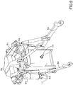
FIG. 2 is a configuration view of a lifting device according to the first embodiment. -
FIG. 3 is a view illustrating a PTO clutch device and a controller device according to the first embodiment. -
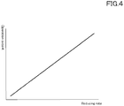
FIG. 4 is a view illustrating a relation between a reducing rate and an operation extent of a rate-setting switch according to the first embodiment. -
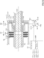
FIG. 5 is a view illustrating a PTO clutch device and a controller device according to a second embodiment of the present invention. -
FIG. 6 is a view illustrating a relation between an increasing rate of a PTO shaft and an electric current (a control signal) outputted to a control valve according to the second embodiment. -
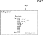
FIG. 7 is a view illustrating an example pf a setting screen M17 according to the second embodiment. -
FIG. 8 is a whole view illustrating a tractor according to the embodiments. - Hereinafter, an embodiment of the present invention will be described with appropriate reference to the drawings.
-
FIG. 8 is a side view showing a workingvehicle 1 according to a first embodiment of the present invention.FIG. 8 is a plan view showing theworking vehicle 1 according to the embodiment. In the present embodiment, theworking vehicle 1 is a tractor. However, the workingvehicle 1 is not limited to the tractor, and may be an agricultural machine (an agricultural vehicle) such as a combine harvester or a transplanter. - Hereinafter, a front side of an operator sitting on an
operator seat 10 of the tractor (the working vehicle) 1 is referred to as the front, a rear side of the operator is referred to as the rear, a left side of the operator is referred to as the left, and a right side of the operator is referred to as the right. In addition, a horizontal direction that is a direction orthogonal to the front-rear direction of the workingvehicle 1 will be described as a machine width direction. - As shown in
FIG. 8 , thetractor 1 includes a vehicle body 3 having atraveling device 7, aprime mover 4, atransmission device 5, and asteering device 11. Thetraveling device 7 is a device having afront wheel 7F and arear wheel 7R. Thefront wheel 7F may be a tire type or a crawler type. In addition, therear wheel 7R may also be a tire type or a crawler type. Theprime mover 4 is an internal combustion engine such as a gasoline engine or a diesel engine, an electric motor, or the like. In this embodiment, theprime mover 4 is a diesel engine. - The
transmission device 5 is configured to switch the propulsive force of thetraveling device 7 by shifting speeds and to switch between the forward traveling and the reverse traveling of thetraveling device 7. Acabin 9 is provided in the vehicle body 3, and anoperator seat 10 is provided in thecabin 9. - An
lifting device 8 is provided at the rear portion of the vehicle body 3. Theworking device 2 can be attached to and detached from thelifting device 8. In addition, thelifting device 8 is configured to lift the attachedworking device 2. Theworking device 2 is a tiller device for the tilling, a fertilizer sprayer device for spraying fertilizer, a pesticide sprayer device for spraying pesticides, a harvester device for the harvesting, a mower device for mowing grass and the like, a tedder device for tedding grass and the like, a raking device for raking grass and the like, a baler device for baling grass and the like, or the like. In addition, inFIG. 8 , an example in which attached the tiller device is attached as theworking device 2 is shown. - As shown in
FIG. 1 , thetransmission device 5 includes a main shaft (a propulsion shaft) 5a, ashuttle portion 5b, amain transmission portion 5c, ansub-transmission portion 5d, aPTO clutch device 5e, and afront transmission portion 5f. Thepropulsion shaft 5a is rotatably supported by a housing case of thetransmission device 5, and the power from the crankshaft of theprime mover 4 is transmitted to thepropulsion shaft 5a. - The
shuttle portion 5b has a shuttle shaft 5b1 and a forward/reverse switching portion 5b2. Power supplied from thepropulsion shaft 5a is transmitted to the shuttle shaft 5b1. The forward/reverse switching portion 5b2 is constituted of, for example, a hydraulic clutch or the like, and switches the revolving direction of the shuttle shaft 5b1, that is, switches between the forward traveling and the backward traveling of thetractor 1 by engaging and disengaging the hydraulic clutch. - The
main transmission portion 5c is a continuously variable transmission mechanism that continuously changes the input power. The continuously variable transmission mechanism has a hydraulic pump 5c1, a hydraulic motor 5c2, and a planetary gear mechanism 5c3. The hydraulic pump 5c1 revolves with the power supplied from the output shaft 5b3 of theshuttle portion 5b. The hydraulic pump 5c1 is, for example, a variable displacement pump having aswash plate 12, and is configured to change the flow rate of the operation fluid outputted from the hydraulic pump 5c1 by changing the angle of the swash plate 12 (a swash plate angle). The hydraulic motor 5c2 is a motor configured to be revolved by the operation fluid outputted from the hydraulic pump 5c1 through a fluid tube circuit such as piping. The revolving speed of the hydraulic motor 5c2 can be changed by changing the swash plate angle of the hydraulic pump 5c1 or changing the power to be inputted to the hydraulic pump 5c1. - The planetary gear mechanism 5c3 is a mechanism constituted of a plurality of gears and a power transmission shaft such as an input shaft and an output shaft, and includes an
input shaft 13 to which the power of the hydraulic pump 5c1 is inputted and includes aninput shaft 14 to which the power of the hydraulic motor 5c2 is inputted. The planetary gear mechanism 5c3 combines the power of the hydraulic pump 5c1 and the power of the hydraulic motor 5c2, and then transmits the combined power to theoutput shaft 15. - Thus, according to the
main transmission portion 5c, the power to be outputted to thesub transmission portion 5d can be changed by changing the swash plate angle of theswash plate 12 of the hydraulic pump 5c1, the revolving speed of theprime mover 4, and the like. Themain transmission portion 5c is constituted of the continuously variable transmission mechanism. However, themain transmission portion 5c may be constituted of a transmission mechanism with stepped gears. - The
sub-transmission portion 5d is a transmission mechanism having a plurality of stepped gears that change the power, and changes and outputs the power inputted from theoutput shaft 15 of the planetary gear mechanism 5c3 to thesub-transmission portion 5d (changes the speed) by appropriately changing the connection (engagement) between the plurality of gears. Thesub-transmission portion 5d includes an input shaft 5d1, a first transmission clutch 5d2, a second transmission clutch 5d3, and an output shaft 5d4. The input shaft 5d1 is a shaft to which the power of theoutput shaft 15 of the planetary gear mechanism 5c3 is inputted, and inputs the inputted power to the first transmission clutch 5d2 and the second transmission clutch 5d3 through the gears or the like. By respectively engaging or the disengaging the first transmission clutch 5d2 and the second transmission clutch 5d3, the inputted power is changed and outputted to the output shaft 5d4. The power outputted to the output shaft 5d4 is transmitted to the rear wheeldifferential device 20R. The rear wheeldifferential device 20R rotatably supports arear axle 21R to which therear wheel 7R is attached. - The PTO
clutch device 5e is constituted of, for example, a hydraulic clutch or the like, and is switched, by turning the hydraulic clutch on and off, between a state in which the power of thepropulsion shaft 5a is transmitted to the PTO propulsion shaft 5e2 (an engaging state) and a state in which the power of thepropulsion shaft 5a is not transmitted to the PTO propulsion shaft 5e2 (a disengaging state). The power of the PTO propulsion shaft 5e2 is transmitted to thePTO shaft 16 through the gears or the like. - The
front transmission portion 5f includes a first front transmission clutch 5f1 and a second front transmission clutch 5f2. The first front transmission clutch 5f1 and the second front transmission clutch 5f2 are capable of transmitting the power that is supplied from thesub-transmission portion 5d, and, for example, the power of the output shaft 5d4 is transmitted through the gears and the transmission shaft. The power supplied from the first front transmission clutch 5f1 and the second front transmission clutch 5f2 can be transmitted to thefront axle shaft 21F through the front power transmission shaft. In particular, the front transmission shaft is connected to the front wheeldifferential device 20F, and the front wheeldifferential device 20F rotatably supports thefront axle 21F to which thefront wheels 7F are attached. - Each of the first front transmission clutch 5f1 and the second front transmission clutch 5f2 is constituted of a hydraulic clutch or the like. A fluid tube is connected to the first front transmission clutch 5f1, and the fluid tube is connected to a
control valve 23 to which the operation fluid outputted from the hydraulic pump is supplied. The first front transmission clutch 5f1 switches between the engaging state and the disengaging state in accordance with the opening aperture of thecontrol valve 23. A fluid tube is connected to the second front transmission clutch 5f2, and thecontrol valve 24 is connected to the fluid tube. The second front transmission clutch 5f2 switches between the engaging state and the disengaging state in accordance with the opening aperture of thecontrol valve 24. Each of thecontrol valve 23 and thecontrol valve 24 is constituted of, for example, a two-position switching valve with a solenoid valve, and are switched to the engaging state or to the disengaging state by magnetizing or demagnetizing the solenoid of the solenoid valve. - When the first front transmission clutch 5f1 is under the disengaging state and the second front transmission clutch 5f2 is under the engaging state, the power of the
sub-transmission portion 5d is transmitted to thefront wheel 7F through the second front transmission clutch 5f2. In this manner, the four-wheel drive (4WD) to drive the front wheels and the rear wheels with the power is established, and the front wheels and the rear wheels have substantially the same revolving speed (the 4WD constant velocity state). On the other hand, when the first front transmission clutch 5f1 is under the engaging state and the second front transmission clutch 5f2 is under the disengaging state, the four-wheel drive is established, and the revolving speeds of the front wheels become faster than the revolving speeds of the rear wheels (4WD speed-increasing state). In addition, when the first front transmission clutch 5f1 and the second front transmission clutch 5f2 are under the engaging state, the power of thesub transmission portion 5d is not supplied to thefront wheels 7F, and thus the four-wheel drive (2WD) to drive the rear wheels with the power is established. - As shown in
FIG. 2 , thelifting device 8 includes alift arm 8a, alower link 8b, atop link 8c, alift rod 8d, and alift cylinder 8e. A front end portion of thelift arm 8a is supported by a rear upper portion of a case (a transmission case) accommodating thetransmission device 5 so as to be swingable upward or downward. Thelift arm 8a is swung (moved up and down) by driving thelift cylinder 8e. Thelift cylinder 8e is constituted of a hydraulic cylinder. Thelift cylinder 8e is connected to the hydraulic pump through the control valve 34. - The front end portion of the
lower link 8b is supported on the lower rear portion of thetransmission device 5 so as to be swingable upward or downward. The front end portion of thetop link 8c is supported by the rear portion of thetransmission device 5 so as to be swingable upward or downward above thelower link 8b. Thelift rod 8d connects thelift arm 8a and thelower link 8b. The workingdevice 2 is connected to the rear portion of thelower link 8b and to the rear portion of thetop link 8c. When thelift cylinder 8e is driven (stretched and shortened), thelift arm 8a is moved up and down, and thelower link 8b connected to thelift arm 8a by thelift rod 8d is moved up and down. In this manner, the workingdevice 2 swings upward or downward (moves up and down) with the front portion of thelower link 8b as a fulcrum. - As shown in
FIG. 3 , the PTOclutch device 5e includes afirst rotor member 151, asecond rotor member 152, and apressing member 153. Thefirst rotor member 151 is fixed to thepropulsion shaft 5a and rotates with the revolving of thepropulsion shaft 5a. Thesecond rotor member 152 is a member that transmits the power to thePTO shaft 16, and is constituted of, for example, a circular disk. The pressingmember 153 is a piston configured to be moved by the pressure of the operation fluid between the engaging side on which thefirst rotor member 151 is pressed to thesecond rotor member 152 and the disengaging side on which thefirst rotor member 151 is disengaged from thesecond rotor member 152. The pressingmember 153 is movably provided in thehousing 154 and moves to the pressing side (the engaging side) G1 side against the biasing force of thespring 155, whereby thefirst rotor member 151 is pressed to the second rotating member, and thepressing member 153 moves to the releasing side (the disengaging side) G2 side with the biasing force of thespring 155, whereby thefirst rotor member 151 is separated from the second rotating member. That is, when thepressing member 153 moved to the pressing side G1, the engaging state in which the power of thepropulsion shaft 5a is transmitted to the PTO propulsion shaft 5e2 is established, and when thepressing member 153 is moved to the disengaging side G2, the disengaging state in which the power of thepropulsion shaft 5a is not transmitted to the PTO propulsion shaft 5e2. - The PTO
clutch device 5e has aPTO brake 157. ThePTO brake 157 is a member configured to reduce the revolving of thePTO shaft 16 when thepressing member 153 is positioned on the disengaging side G2. ThePTO brake 157 includes afirst contact member 157a configured to move in accordance with the movement of thepressing member 153, and includes asecond contact member 157b configured to be fixed to thehousing 154 or the like. Thefirst contact member 157a is fixed to thepressing member 153. When thepressing member 153 moves to the engaging side G1, thefirst contact member 157a moves in a direction separating away from thesecond contact member 157b, and when thepressing member 153 moves to the disengaging side G2, thefirst contact member 157a moves toward thesecond contact member 157b. Thefirst contact member 157a and thesecond contact member 157b have facing surfaces that face each other. The facing surface of thefirst contact member 157a and the facing surface of thesecond contact member 157b are pressed to each other when thepressing member 153 moves to the disengaging side G2, the braking is applied. The facing surface of thefirst contact member 157a and the facing surface of thesecond contact member 157b are separated from each other when thepressing member 153 moves to the engaging side G1, the braking is released. - A
supply chamber 158 for supplying the operation fluid is formed in thehousing 154, and thepressing member 153 is moved in thehousing 154 by the pressure of the operation fluid supplied to thesupply chamber 158. A fluid tube 160 is connected to thesupply chamber 158, and acontrol valve 161 is connected to the fluid tube 160. Thecontrol valve 161 is a valve configured to control the PTOclutch device 5e, that is, to control the pressure of the operation fluid in thesupply chamber 158. And, thecontrol valve 161 is, for example, a proportional solenoid valve configured to switch between afirst position 161A and a second position 162B. The operation fluid from thehydraulic pump 162 is supplied to thecontrol valve 161. When thecontrol valve 161 is set to thefirst position 161A, the operation fluid is supplied to thesupply chamber 158, and thus the pressure in thesupply chamber 158 is increased. When thecontrol valve 161 is set to thesecond position 161B, the operation fluid in thesupply chamber 158 passes through thecontrol valve 161 and is discharged to the discharge portion such as the operation fluid tank, so that the pressure in thesupply chamber 158 is reduced. - In this manner, the PTO
clutch device 5e is capable of being switched between the engaging state and the disengaging state by switching thecontrol valve 161 to either thefirst position 161A or thesecond position 161B. In particular, the revolving of thePTO shaft 16 can be stopped by the braking of thePTO brake 157 simultaneously when the PTOclutch device 5e is set to the disengaging state. - As shown in
FIG. 3 , thetractor 1 includes acontroller device 40. Thecontroller device 40 is a device configured to perform various controls of thetractor 1, and, for example, performs the lifting control, the PTO control, and the like. In the lifting control, thecontroller device 40 magnetizes the solenoid of the control valve 34 to switch the control valve 34 to the lifting position when a command for the lifting is issued through operation of thelifting operation tool 171. In this manner, thelift cylinder 8e is stretched, and the rear end portion of thelift arm 8a (the end portion on the workingdevice 2 side) is lifted. - In the lifting control, when the lifting
operation tool 171 is operated in a lowering direction (a lowering side), thecontroller device 40 magnetizes the solenoid of the control valve 34 to switch the control valve 34 to the lowering position. In this manner, thelift cylinder 8e is shortened, and the rear end portion of thelift arm 8a (the end portion on the workingdevice 2 side) is lowered. - In addition, the
controller device 40 stops the lifting operation of thelifting device 8 when the angle of thelift arm 8a reaches the position of the workingdevice 2, that is, reaches the upper limit (the upper limit value of height) set by the upperlimit setting dial 172 under the state where the workingdevice 2 is moved upward by thelifting device 8. - In addition, a
PTO switching member 164 is connected to thecontroller device 40. ThePTO switching member 164 is constituted of a seesaw switch, a button switch, a slide switch, or the like, and is configured to be switched on and off. In the PTO control, when thePTO switching member 164 is switched on, thecontroller device 40 magnetizes thesolenoid 161C of thecontrol valve 161 to switch thecontrol valve 161 to thefirst position 161A. Additionally in the PTO control, when thePTO switching member 164 is switched off, thecontroller device 40 demagnetizes thesolenoid 161C of thecontrol valve 161 to switch thecontrol valve 161 to thesecond position 161B. - In addition, a
rate setting portion 165A is connected to thecontroller device 40. Therate setting portion 165A is configured to set the reducing rate of the pressure of the operation fluid when the control valve 61 is switched to thesecond position 161B, that is, when the operation fluid in thesupply chamber 158 of the PTOclutch device 5e is discharged to the outside to reduce the pressure of the operation fluid applied to the supply chamber 158 (a working pressure). Therate setting portion 165A is, for example, a rate setting switch with which the operator manually sets the reducing speed. The rate setting switch is a hardware switch, and is a volume switch (a turn switch) having acylindrical knob 165a capable of turning about thevertical axis 165b. As shown inFIG. 4 , when theknob 165a is turned in one direction, the reducing rate to be set becomes small, and when turned in the other direction, the reducing rate to be set becomes large. - The
controller device 40 controls the control valve 61 based on the reducing rate set by therate setting portion 165A. In particular, when the reducing rate set by therate setting portion 165A is high, thecontroller device 40 increases the speed (a switching speed) at which thecontrol valve 161 is switched from thefirst position 161A to thesecond position 161B, thereby increasing the reducing rate of the working pressure in thesupply chamber 158. In addition, when the reducing rate set by therate setting portion 165A is small, thecontroller device 40 slows the switching speed at which thecontrol valve 161 is switched from thefirst position 161A to thesecond position 161B, so that the reducing rate of the working pressure in thesupply chamber 158 is increased. As described above, thecontroller device 40 and therate setting portion 165A change the reducing rate of the working pressure in thesupply chamber 158 to adjust the braking force of the PTO brake 157 per unit time. According to this configuration, since the inertial force of thePTO shaft 16 differs depending on the type of the workingdevice 2, the braking force of thePTO brake 157 that works at the same time when thePTO brake 157 is disengaged can be weakened by decreasing the reducing speed with therate setting portion 165A in the case where the inertial force is large. And, it is possible to prevent the burn-in due to the pressured contact between thefirst contact member 157a and thesecond contact member 157b, thereby extending the life of thePTO brake 157. On the other hand, when the inertial force is small, the braking force of thePTO brake 157 can be increased by increasing the reducing rate with therate setting portion 165A, and thus thePTO shaft 16 can be stopped quickly. That is, the driver can change the reducing rate while predicting the inertial force, simultaneously confirming the type and state of the workingdevice 2, and thereby it is possible to quickly rotate thePTO shaft 16 while preventing the burn-in. -
FIG. 5 is a view showing a PTO clutch device and a controller device according to a second embodiment of the present invention. In the second embodiment, the description of the configurations same as those of the first embodiment will be omitted. - As shown in
FIG. 5 , thecontroller device 40 includes arate setting portion 165B. Therate setting portion 165B is constituted of an electric / electronic circuit provided in thecontroller device 40, a computer program stored in thecontroller device 40, or the like. - The
rate setting portion 165B sets the reducing rate based on the revolving speed of thePTO shaft 16 when thepressing member 153 of the PTOclutch device 5e is moved to the engaging side. In particular, thecontroller device 40 is connected to a revolvingdetector device 169 configured to detect the revolving speed of thePTO shaft 16. - As shown in
FIG. 6 , when thePTO switching member 164 is switched on at the point P10 under the state where the workingdevice 2 and thePTO shaft 16 are connected to each other, the controller device 40 (therate setting portion 165B) reduces the electric current value A1 after instantaneously increasing the current value A1 to be outputted to thesolenoid 161C of the control valve 161 (a one-shot section T1), and then gradually increases the current value A1 (a modulation section T2). In addition, therate setting portion 165B monitors the increasing tendency of the revolving speed of thePTO shaft 16 detected by the revolvingdetector device 169 in the modulation section T2 in which the current value A1 is gradually increased, that is, in the modulation section T2 in which the current (the control signal) outputted to the control valve 61is gradually increased by the controller device 40 (therate setting portion 165B). For example, therate setting portion 165B obtains, with the least square method or the like, the increasing rate (inclination) A2 based on the revolving speeds of the plurality ofPTO shafts 16 in the modulation section T2. When the increasing rate (inclination) A2 is smaller than a predetermined reference rate (inclination) A3, therate setting portion 165B reduces the reducing rate, and when the increasing rate (inclination) A2 is larger than the reference rate (inclination) A3, therate setting portion 165A increases the reducing rate. That is, under the state where the workingdevice 2 is driven by thePTO shaft 16, it can be assumed that the inertial force generated when stopping the workingdevice 2 is large when the increasing speed A2 is small, and that the inertial force generated when stopping the workingdevice 2 is small when the increasing speed A2 is large. As described above, the reducing rate can be easily set according to the inertial force estimated in driving the workingdevice 2. - In addition, the setting of the reducing rate with the
rate setting portion 165B may be performed in initially driving the workingdevice 2 with the power of thePTO shaft 16, for example, when the working is started, that is, when the workingdevice 2 is connected to thelifting device 8 and thePTO shaft 16 is connected to the workingdevice 2. And, the setting of the reducing rate with therate setting portion 165B may be performed in reengaging the PTOclutch device 5e after the disengaging of the PTOclutch device 5e. In addition, therate setting portion 165B sets the reducing rate when thelifting device 8 is in the ascending position, that is, when the lifting device 65B is positioned at the lifting position, that is when the lifting instruction is issued by the liftingoperation tool 171. In addition, therate setting portion 165B may set the reducing rate when thelifting device 8 is positioned at the lowered position. - The sensitivity (frequency) for setting the reducing rate with the
rate setting portion 165B may be arbitrarily changed. For example, as shown inFIG. 7 , when a predetermined operation is performed on the display device 45, the display device 45 displays the setting screen M17. The setting screen M17 displays a sensitivity setting tool 410. The sensitivity setting tool 410 includes a scale portion 410a and an index portion 410b. The scale portion 410a is a portion for displaying the sensitivity (the frequency), the one side has high sensitivity and the other side has low sensitivity. - The index portion 410b is movable with respect to the scale portion 410a, and is a portion for selecting the sensitivity. According to the sensitivity setting tool 410, when the sensitivity is increased, the setting frequency of the reducing rate by the
rate setting portion 165B is increased in reengaging the PTOclutch device 5e after disengaging once (when re-engaging), and when the sensitivity is decreased, the setting frequency is decreased in reengaging. - The working
vehicle 1 includes: thePTO shaft 16 to transmit, to the workingdevice 2, the power of thepropulsion shaft 5a through which the power of theprime mover 4 is transmitted; the PTOclutch device 5e having: thefirst rotor member 151 to be rotated by the power of thepropulsion shaft 5a; thesecond rotor member 152 to transmit the power to thePTO shaft 16; the pressingmember 153 to be moved by the pressure of the operation fluid between the engaging side on which thefirst rotor member 151 is engaged with thesecond rotor member 152 and the disengaging side on which thefirst rotor member 151 is disengaged from thesecond rotor member 152; and thePTO brake 157 to brake thePTO shaft 16 when thepressing member 153 is positioned on the disengaging side; the control valve (a pressure control valve) 161 to control the pressure of the operation fluid to be applied to the PTOclutch device 5e; the rate-settingportions control valve 161, a reducing rate at which the pressure of the operation fluid is reduced; and thecontroller device 40 to control thecontrol valve 161 based on the reducing rate set by the rate-settingportions rate setting portions device 2 generating a large inertial force during operation and the workingdevice 2 generating a small inertial force during operation. Thus, the braking of the PTO shaft can be appropriately performed depending on the type of the workingdevice 2. - The rate-setting portion is the rate-setting
switch 165A allowing the operator to manually set the reducing rate. According to this configuration, the reducing rate can be controlled while judging the situation where the operator operates the workingdevice 2, for example, the magnitude of the load or the inertial force. - The working
vehicle 1 includes the revolvingdetector device 169 to detect a revolving speed of thePTO shaft 16. The rate-settingportion 165B sets the reducing rate based on the revolving speed of thePTO shaft 16, the revolving speed being detected by the revolvingdetector device 169 when thepressing member 153 is moved to the engaging side. According to this configuration, the reducing rate can be set in accordance with the transition of the revolving speed of thePTO shaft 16, the transition being caused when the workingdevice 2 is connected to the vehicle body 3 to drive thePTO shaft 16. - The rate-setting portion 165 sets the reducing rate based on a relation between the revolving speed of the
PTO shaft 16 and a control signal outputted to thecontrol valve 161, the revolving speed and the control signal being provided at a timing when thepressing member 153 is moved to the engaging side. According to this configuration, the reducing rate can be set in accordance with the transition of the revolving speed of thePTO shaft 16, the transition being caused when thecontrol valve 161 is operated, for example, when thefirst rotor member 151 and thesecond rotor member 152 are engaged by the pressingmember 153. For example, in the case where the working is performed by the workingdevice 2, the reducing rate can be set depending on the increasing transition of the revolving speed of thePTO shaft 16, the increasing transition being caused when the workingdevice 2 is initially driven by thePTO shaft 16. - The rate-setting
portion 165B lowers the reducing rate when the increasing rate of the revolving speed of thePTO shaft 16 is smaller than the reference rate preliminarily determined and raises the reducing rate when the increasing rate is larger than the reference rate, with respect to the electric current value outputted as the control signal to thecontrol valve 161. For example, it can be determined that the inertial force is large when the increasing rate of the revolving speed of thePTO shaft 16 is smaller than the reference speed, the increasing rate being caused when the workingdevice 2 is initially driven by thePTO shaft 16, and determined that the inertial force is small when the increasing rate of the revolving speed of thePTO shaft 16 is larger than the reference speed. And, when the inertial force is large, it is possible to suppress wear of thePTO brake 157 or the like by reducing the reducing rate. - The rate-setting
portion 165B has the display device 45 configured to allow to set the sensitivity of the reducing rate. According to this configuration, the reducing rate can be set in accordance with various types of the workingdevices 2 by changing the frequency of setting the reducing rate, that is, by changing the sensitivity in automatically setting the reducing rate. - In the above description, the embodiment of the present invention has been explained. However, all the features of the embodiment disclosed in this application should be considered just as examples, and the embodiment does not restrict the present invention accordingly. A scope of the present invention is shown not in the above-described embodiment but in claims, and is intended to include all modifications within and equivalent to a scope of the claims.
-
- 1
- Working vehicle (Tractor)
- 2
- Working device
- 3
- Vehicle body
- 4
- Prime mover
- 5
- Propulsion shaft
- 5e
- PTO clutch device
- 16
- PTO shaft
- 45
- Display device
- 151
- First rotor member
- 152
- Second rotor member
- 153
- Pressing member
- 161
- Control valve
- 165A, 165B
- Rate setting portion
Claims (6)
- A working vehicle (1) comprising:a PTO shaft (16) to transmit, to a working device (2), power of a propulsion shaft through which power of a prime mover (4) is transmitted;a PTO clutch device (5e) having:a first rotor member (151) to be rotated by the power of the propulsion shaft;a second rotor member (152) to transmit the power to the PTO shaft (16);a pressing member (153) to be moved by a pressure of operation fluid between an engaging side on which the first rotor member (151) is engaged with the second rotor member (152) and a disengaging side on which the first rotor member (151) is disengaged from the second rotor member (152); anda PTO brake (157) to brake the PTO shaft (16) when the pressing member (153) is positioned on the disengaging side;a control valve (161) to control the pressure of the operation fluid to be applied to the PTO clutch device (5e);a rate-setting portion (165A, 165B) to set, with the control valve (161), a reducing rate at which the pressure of the operation fluid is reduced; anda controller device (40) to control the control valve (161) based on the reducing rate set by the rate-setting portion (165A, 165B).
- The working vehicle (1) according to claim 1,
wherein the rate-setting portion (165A, 165B) is a rate-setting switch allowing an operator to manually set the reducing rate. - The working vehicle (1) according to claim 1, comprising
a revolving detector device (169) to detect a revolving speed of the PTO shaft (16),
wherein the rate-setting portion (165A, 165B) sets the reducing rate based on the revolving speed of the PTO shaft (16), the revolving speed being detected by the revolving detector device (169) when the pressing member (153) is moved to the engaging side. - The working vehicle (1) according to claim 3,
wherein the rate-setting portion (165A, 165B) sets the reducing rate based on a relation between the revolving speed of the PTO shaft (16) and a control signal outputted to the control valve (161), the revolving speed and the control signal being provided at a timing when the pressing member (153) is moved to the engaging side. - The working vehicle (1) according to claim 4,
wherein the rate-setting portion (165A, 165B) lowers the reducing rate when an increasing rate of the revolving speed of the PTO shaft (16) is smaller than a reference rate preliminarily determined and raises the reducing rate when the increasing rate is larger than the reference rate, with respect to an electric current value outputted as the control signal to the control valve (161). - The working vehicle (1) according to any one of claims 1 to 5,
wherein the rate-setting portion (165A,165B) has
a display device (45) configured to allow to set sensitivity of the reducing rate.
Applications Claiming Priority (1)
| Application Number | Priority Date | Filing Date | Title |
|---|---|---|---|
| JP2019109104A JP7091286B2 (en) | 2019-06-11 | 2019-06-11 | Work vehicle |
Publications (2)
| Publication Number | Publication Date |
|---|---|
| EP3750739A1 true EP3750739A1 (en) | 2020-12-16 |
| EP3750739B1 EP3750739B1 (en) | 2025-02-26 |
Family
ID=71094083
Family Applications (1)
| Application Number | Title | Priority Date | Filing Date |
|---|---|---|---|
| EP20178821.3A Active EP3750739B1 (en) | 2019-06-11 | 2020-06-08 | Working vehicle |
Country Status (3)
| Country | Link |
|---|---|
| US (1) | US11247557B2 (en) |
| EP (1) | EP3750739B1 (en) |
| JP (1) | JP7091286B2 (en) |
Families Citing this family (4)
| Publication number | Priority date | Publication date | Assignee | Title |
|---|---|---|---|---|
| IT201700047756A1 (en) * | 2017-05-03 | 2018-11-03 | Cnh Ind Italia Spa | PTO UNIT WITH PLANETARY GEAR PROVIDED WITH HYDRAULIC CONTROL, WORKING VEHICLE INCLUDING THE SAME AND ESTIMATE METHOD OF THE TORQUE SUPPLIED BY THE TAKE-UP |
| DE102019214412B4 (en) * | 2019-09-23 | 2025-09-04 | Zf Friedrichshafen Ag | Method for operating a drive train for a work machine, drive train for a work machine and work machine |
| JP7480084B2 (en) * | 2021-03-17 | 2024-05-09 | 株式会社クボタ | Power transmission device for work vehicle |
| JP7858578B2 (en) * | 2023-03-14 | 2026-05-14 | 株式会社クボタ | Work vehicles |
Citations (5)
| Publication number | Priority date | Publication date | Assignee | Title |
|---|---|---|---|---|
| US4760902A (en) * | 1984-04-05 | 1988-08-02 | Massey-Ferguson Services N.V. | Clutch engagement control system |
| US5601172A (en) * | 1994-08-01 | 1997-02-11 | Case Corporation | Power take off clutch engagement control system for cold weather starting |
| US7048106B2 (en) * | 2004-03-26 | 2006-05-23 | Cnh America Llc | Power take-off control system and method |
| JP2007269061A (en) | 2006-03-30 | 2007-10-18 | Kubota Corp | Tractor PTO transmission structure |
| GB2442700A (en) * | 2006-10-11 | 2008-04-16 | James Fox | Safety device for power take off shaft |
Family Cites Families (6)
| Publication number | Priority date | Publication date | Assignee | Title |
|---|---|---|---|---|
| US5494142A (en) | 1994-08-01 | 1996-02-27 | Case Corporation | Power take off clutch engagement control system |
| JP4233402B2 (en) * | 2003-04-17 | 2009-03-04 | 株式会社 神崎高級工機製作所 | Power split device for work vehicle |
| EP1630030A3 (en) * | 2004-08-24 | 2008-04-09 | Kanzaki Kokyukoki MFG. Co., Ltd. | Pump system and axle-driving system |
| JP2015054578A (en) * | 2013-09-11 | 2015-03-23 | 株式会社 神崎高級工機製作所 | Travel transmission gear for work vehicle |
| JP2015171880A (en) * | 2014-02-21 | 2015-10-01 | 株式会社 神崎高級工機製作所 | Transmission for work vehicle |
| JP2015209152A (en) * | 2014-04-28 | 2015-11-24 | 株式会社 神崎高級工機製作所 | Axle drive unit of work vehicle |
-
2019
- 2019-06-11 JP JP2019109104A patent/JP7091286B2/en active Active
-
2020
- 2020-06-05 US US16/893,490 patent/US11247557B2/en active Active
- 2020-06-08 EP EP20178821.3A patent/EP3750739B1/en active Active
Patent Citations (5)
| Publication number | Priority date | Publication date | Assignee | Title |
|---|---|---|---|---|
| US4760902A (en) * | 1984-04-05 | 1988-08-02 | Massey-Ferguson Services N.V. | Clutch engagement control system |
| US5601172A (en) * | 1994-08-01 | 1997-02-11 | Case Corporation | Power take off clutch engagement control system for cold weather starting |
| US7048106B2 (en) * | 2004-03-26 | 2006-05-23 | Cnh America Llc | Power take-off control system and method |
| JP2007269061A (en) | 2006-03-30 | 2007-10-18 | Kubota Corp | Tractor PTO transmission structure |
| GB2442700A (en) * | 2006-10-11 | 2008-04-16 | James Fox | Safety device for power take off shaft |
Also Published As
| Publication number | Publication date |
|---|---|
| JP2020199934A (en) | 2020-12-17 |
| EP3750739B1 (en) | 2025-02-26 |
| US20200391589A1 (en) | 2020-12-17 |
| US11247557B2 (en) | 2022-02-15 |
| JP7091286B2 (en) | 2022-06-27 |
Similar Documents
| Publication | Publication Date | Title |
|---|---|---|
| EP3750739B1 (en) | Working vehicle | |
| KR101562089B1 (en) | Speed control structure for work vehicle, information display structure therefor, and speed shift manipulating structure therefor | |
| US8127872B2 (en) | Transmission device for work vehicle | |
| US11951827B2 (en) | Work vehicle | |
| US10960925B2 (en) | Work vehicle | |
| US12419206B2 (en) | Working machine | |
| JP5745227B2 (en) | Shifting operation structure of work vehicle | |
| JP7716652B2 (en) | Work vehicles | |
| EP3832166B1 (en) | Working vehicle | |
| JP2001108061A (en) | Traveling speed control device | |
| JP2019199952A (en) | Work vehicle | |
| JP5169537B2 (en) | Work vehicle | |
| US12055212B2 (en) | Electromagnetic valve control device and work vehicle | |
| US11268614B2 (en) | Working vehicle | |
| JP7130598B2 (en) | work vehicle | |
| JP5351784B2 (en) | Speed control structure of work vehicle | |
| JP6671194B2 (en) | Work vehicle | |
| JP3982037B2 (en) | Front-wheel drive device for power farm equipment | |
| JP5261407B2 (en) | Information display structure of work vehicle | |
| JP2012130304A (en) | Combine harvester | |
| JPH04356289A (en) | Controlling device for center of gravity of agricultural ground work vehicle | |
| JP5805945B2 (en) | Combine | |
| JP2002144903A (en) | Tractor | |
| CN113993743B (en) | Work vehicle | |
| JP3982035B2 (en) | Front-wheel drive device for power farm equipment |
Legal Events
| Date | Code | Title | Description |
|---|---|---|---|
| PUAI | Public reference made under article 153(3) epc to a published international application that has entered the european phase |
Free format text: ORIGINAL CODE: 0009012 |
|
| STAA | Information on the status of an ep patent application or granted ep patent |
Free format text: STATUS: REQUEST FOR EXAMINATION WAS MADE |
|
| 17P | Request for examination filed |
Effective date: 20200608 |
|
| AK | Designated contracting states |
Kind code of ref document: A1 Designated state(s): AL AT BE BG CH CY CZ DE DK EE ES FI FR GB GR HR HU IE IS IT LI LT LU LV MC MK MT NL NO PL PT RO RS SE SI SK SM TR |
|
| AX | Request for extension of the european patent |
Extension state: BA ME |
|
| STAA | Information on the status of an ep patent application or granted ep patent |
Free format text: STATUS: EXAMINATION IS IN PROGRESS |
|
| 17Q | First examination report despatched |
Effective date: 20211221 |
|
| GRAP | Despatch of communication of intention to grant a patent |
Free format text: ORIGINAL CODE: EPIDOSNIGR1 |
|
| STAA | Information on the status of an ep patent application or granted ep patent |
Free format text: STATUS: GRANT OF PATENT IS INTENDED |
|
| INTG | Intention to grant announced |
Effective date: 20241106 |
|
| GRAS | Grant fee paid |
Free format text: ORIGINAL CODE: EPIDOSNIGR3 |
|
| GRAA | (expected) grant |
Free format text: ORIGINAL CODE: 0009210 |
|
| STAA | Information on the status of an ep patent application or granted ep patent |
Free format text: STATUS: THE PATENT HAS BEEN GRANTED |
|
| AK | Designated contracting states |
Kind code of ref document: B1 Designated state(s): AL AT BE BG CH CY CZ DE DK EE ES FI FR GB GR HR HU IE IS IT LI LT LU LV MC MK MT NL NO PL PT RO RS SE SI SK SM TR |
|
| REG | Reference to a national code |
Ref country code: GB Ref legal event code: FG4D |
|
| REG | Reference to a national code |
Ref country code: CH Ref legal event code: EP |
|
| REG | Reference to a national code |
Ref country code: DE Ref legal event code: R096 Ref document number: 602020046647 Country of ref document: DE |
|
| REG | Reference to a national code |
Ref country code: IE Ref legal event code: FG4D |
|
| REG | Reference to a national code |
Ref country code: NL Ref legal event code: MP Effective date: 20250226 |
|
| PG25 | Lapsed in a contracting state [announced via postgrant information from national office to epo] |
Ref country code: RS Free format text: LAPSE BECAUSE OF FAILURE TO SUBMIT A TRANSLATION OF THE DESCRIPTION OR TO PAY THE FEE WITHIN THE PRESCRIBED TIME-LIMIT Effective date: 20250526 |
|
| PG25 | Lapsed in a contracting state [announced via postgrant information from national office to epo] |
Ref country code: FI Free format text: LAPSE BECAUSE OF FAILURE TO SUBMIT A TRANSLATION OF THE DESCRIPTION OR TO PAY THE FEE WITHIN THE PRESCRIBED TIME-LIMIT Effective date: 20250226 |
|
| PG25 | Lapsed in a contracting state [announced via postgrant information from national office to epo] |
Ref country code: PL Free format text: LAPSE BECAUSE OF FAILURE TO SUBMIT A TRANSLATION OF THE DESCRIPTION OR TO PAY THE FEE WITHIN THE PRESCRIBED TIME-LIMIT Effective date: 20250226 |
|
| PGFP | Annual fee paid to national office [announced via postgrant information from national office to epo] |
Ref country code: DE Payment date: 20250617 Year of fee payment: 6 |
|
| PG25 | Lapsed in a contracting state [announced via postgrant information from national office to epo] |
Ref country code: ES Free format text: LAPSE BECAUSE OF FAILURE TO SUBMIT A TRANSLATION OF THE DESCRIPTION OR TO PAY THE FEE WITHIN THE PRESCRIBED TIME-LIMIT Effective date: 20250226 |
|
| REG | Reference to a national code |
Ref country code: LT Ref legal event code: MG9D |
|
| PG25 | Lapsed in a contracting state [announced via postgrant information from national office to epo] |
Ref country code: IS Free format text: LAPSE BECAUSE OF FAILURE TO SUBMIT A TRANSLATION OF THE DESCRIPTION OR TO PAY THE FEE WITHIN THE PRESCRIBED TIME-LIMIT Effective date: 20250626 Ref country code: NO Free format text: LAPSE BECAUSE OF FAILURE TO SUBMIT A TRANSLATION OF THE DESCRIPTION OR TO PAY THE FEE WITHIN THE PRESCRIBED TIME-LIMIT Effective date: 20250526 |
|
| PG25 | Lapsed in a contracting state [announced via postgrant information from national office to epo] |
Ref country code: NL Free format text: LAPSE BECAUSE OF FAILURE TO SUBMIT A TRANSLATION OF THE DESCRIPTION OR TO PAY THE FEE WITHIN THE PRESCRIBED TIME-LIMIT Effective date: 20250226 |
|
| PG25 | Lapsed in a contracting state [announced via postgrant information from national office to epo] |
Ref country code: HR Free format text: LAPSE BECAUSE OF FAILURE TO SUBMIT A TRANSLATION OF THE DESCRIPTION OR TO PAY THE FEE WITHIN THE PRESCRIBED TIME-LIMIT Effective date: 20250226 |
|
| PG25 | Lapsed in a contracting state [announced via postgrant information from national office to epo] |
Ref country code: PT Free format text: LAPSE BECAUSE OF FAILURE TO SUBMIT A TRANSLATION OF THE DESCRIPTION OR TO PAY THE FEE WITHIN THE PRESCRIBED TIME-LIMIT Effective date: 20250626 Ref country code: LV Free format text: LAPSE BECAUSE OF FAILURE TO SUBMIT A TRANSLATION OF THE DESCRIPTION OR TO PAY THE FEE WITHIN THE PRESCRIBED TIME-LIMIT Effective date: 20250226 |
|
| PGFP | Annual fee paid to national office [announced via postgrant information from national office to epo] |
Ref country code: FR Payment date: 20250430 Year of fee payment: 6 |
|
| PG25 | Lapsed in a contracting state [announced via postgrant information from national office to epo] |
Ref country code: GR Free format text: LAPSE BECAUSE OF FAILURE TO SUBMIT A TRANSLATION OF THE DESCRIPTION OR TO PAY THE FEE WITHIN THE PRESCRIBED TIME-LIMIT Effective date: 20250527 Ref country code: BG Free format text: LAPSE BECAUSE OF FAILURE TO SUBMIT A TRANSLATION OF THE DESCRIPTION OR TO PAY THE FEE WITHIN THE PRESCRIBED TIME-LIMIT Effective date: 20250226 |
|
| REG | Reference to a national code |
Ref country code: AT Ref legal event code: MK05 Ref document number: 1770326 Country of ref document: AT Kind code of ref document: T Effective date: 20250226 |
|
| PG25 | Lapsed in a contracting state [announced via postgrant information from national office to epo] |
Ref country code: SE Free format text: LAPSE BECAUSE OF FAILURE TO SUBMIT A TRANSLATION OF THE DESCRIPTION OR TO PAY THE FEE WITHIN THE PRESCRIBED TIME-LIMIT Effective date: 20250226 |
|
| PG25 | Lapsed in a contracting state [announced via postgrant information from national office to epo] |
Ref country code: SM Free format text: LAPSE BECAUSE OF FAILURE TO SUBMIT A TRANSLATION OF THE DESCRIPTION OR TO PAY THE FEE WITHIN THE PRESCRIBED TIME-LIMIT Effective date: 20250226 |
|
| PG25 | Lapsed in a contracting state [announced via postgrant information from national office to epo] |
Ref country code: DK Free format text: LAPSE BECAUSE OF FAILURE TO SUBMIT A TRANSLATION OF THE DESCRIPTION OR TO PAY THE FEE WITHIN THE PRESCRIBED TIME-LIMIT Effective date: 20250226 |
|
| PG25 | Lapsed in a contracting state [announced via postgrant information from national office to epo] |
Ref country code: IT Free format text: LAPSE BECAUSE OF FAILURE TO SUBMIT A TRANSLATION OF THE DESCRIPTION OR TO PAY THE FEE WITHIN THE PRESCRIBED TIME-LIMIT Effective date: 20250226 |
|
| PG25 | Lapsed in a contracting state [announced via postgrant information from national office to epo] |
Ref country code: AT Free format text: LAPSE BECAUSE OF FAILURE TO SUBMIT A TRANSLATION OF THE DESCRIPTION OR TO PAY THE FEE WITHIN THE PRESCRIBED TIME-LIMIT Effective date: 20250226 |
|
| PG25 | Lapsed in a contracting state [announced via postgrant information from national office to epo] |
Ref country code: EE Free format text: LAPSE BECAUSE OF FAILURE TO SUBMIT A TRANSLATION OF THE DESCRIPTION OR TO PAY THE FEE WITHIN THE PRESCRIBED TIME-LIMIT Effective date: 20250226 Ref country code: CZ Free format text: LAPSE BECAUSE OF FAILURE TO SUBMIT A TRANSLATION OF THE DESCRIPTION OR TO PAY THE FEE WITHIN THE PRESCRIBED TIME-LIMIT Effective date: 20250226 |
|
| PG25 | Lapsed in a contracting state [announced via postgrant information from national office to epo] |
Ref country code: RO Free format text: LAPSE BECAUSE OF FAILURE TO SUBMIT A TRANSLATION OF THE DESCRIPTION OR TO PAY THE FEE WITHIN THE PRESCRIBED TIME-LIMIT Effective date: 20250226 |
|
| PG25 | Lapsed in a contracting state [announced via postgrant information from national office to epo] |
Ref country code: SK Free format text: LAPSE BECAUSE OF FAILURE TO SUBMIT A TRANSLATION OF THE DESCRIPTION OR TO PAY THE FEE WITHIN THE PRESCRIBED TIME-LIMIT Effective date: 20250226 |
|
| REG | Reference to a national code |
Ref country code: DE Ref legal event code: R097 Ref document number: 602020046647 Country of ref document: DE |
|
| PLBE | No opposition filed within time limit |
Free format text: ORIGINAL CODE: 0009261 |
|
| STAA | Information on the status of an ep patent application or granted ep patent |
Free format text: STATUS: NO OPPOSITION FILED WITHIN TIME LIMIT |
|
| REG | Reference to a national code |
Ref country code: CH Ref legal event code: L10 Free format text: ST27 STATUS EVENT CODE: U-0-0-L10-L00 (AS PROVIDED BY THE NATIONAL OFFICE) Effective date: 20260107 |
|
| REG | Reference to a national code |
Ref country code: CH Ref legal event code: H13 Free format text: ST27 STATUS EVENT CODE: U-0-0-H10-H13 (AS PROVIDED BY THE NATIONAL OFFICE) Effective date: 20260127 |
|
| PG25 | Lapsed in a contracting state [announced via postgrant information from national office to epo] |
Ref country code: MC Free format text: LAPSE BECAUSE OF FAILURE TO SUBMIT A TRANSLATION OF THE DESCRIPTION OR TO PAY THE FEE WITHIN THE PRESCRIBED TIME-LIMIT Effective date: 20250226 |
|
| 26N | No opposition filed |
Effective date: 20251127 |
|
| PG25 | Lapsed in a contracting state [announced via postgrant information from national office to epo] |
Ref country code: LU Free format text: LAPSE BECAUSE OF NON-PAYMENT OF DUE FEES Effective date: 20250608 |
|
| GBPC | Gb: european patent ceased through non-payment of renewal fee |
Effective date: 20250608 |
|
| REG | Reference to a national code |
Ref country code: BE Ref legal event code: MM Effective date: 20250630 |
|
| PG25 | Lapsed in a contracting state [announced via postgrant information from national office to epo] |
Ref country code: GB Free format text: LAPSE BECAUSE OF NON-PAYMENT OF DUE FEES Effective date: 20250608 |
|
| PG25 | Lapsed in a contracting state [announced via postgrant information from national office to epo] |
Ref country code: IE Free format text: LAPSE BECAUSE OF NON-PAYMENT OF DUE FEES Effective date: 20250608 |
|
| PG25 | Lapsed in a contracting state [announced via postgrant information from national office to epo] |
Ref country code: BE Free format text: LAPSE BECAUSE OF NON-PAYMENT OF DUE FEES Effective date: 20250630 |
|
| PG25 | Lapsed in a contracting state [announced via postgrant information from national office to epo] |
Ref country code: CH Free format text: LAPSE BECAUSE OF NON-PAYMENT OF DUE FEES Effective date: 20250630 |