EP3750730A1 - Powertrain and vehicle provided with same - Google Patents
Powertrain and vehicle provided with same Download PDFInfo
- Publication number
- EP3750730A1 EP3750730A1 EP19751819.4A EP19751819A EP3750730A1 EP 3750730 A1 EP3750730 A1 EP 3750730A1 EP 19751819 A EP19751819 A EP 19751819A EP 3750730 A1 EP3750730 A1 EP 3750730A1
- Authority
- EP
- European Patent Office
- Prior art keywords
- electric motor
- transmission
- controller
- powertrain
- case body
- Prior art date
- Legal status (The legal status is an assumption and is not a legal conclusion. Google has not performed a legal analysis and makes no representation as to the accuracy of the status listed.)
- Pending
Links
Images


Classifications
-
- B—PERFORMING OPERATIONS; TRANSPORTING
- B60—VEHICLES IN GENERAL
- B60K—ARRANGEMENT OR MOUNTING OF PROPULSION UNITS OR OF TRANSMISSIONS IN VEHICLES; ARRANGEMENT OR MOUNTING OF PLURAL DIVERSE PRIME-MOVERS IN VEHICLES; AUXILIARY DRIVES FOR VEHICLES; INSTRUMENTATION OR DASHBOARDS FOR VEHICLES; ARRANGEMENTS IN CONNECTION WITH COOLING, AIR INTAKE, GAS EXHAUST OR FUEL SUPPLY OF PROPULSION UNITS IN VEHICLES
- B60K17/00—Arrangement or mounting of transmissions in vehicles
- B60K17/04—Arrangement or mounting of transmissions in vehicles characterised by arrangement, location or kind of gearing
-
- B—PERFORMING OPERATIONS; TRANSPORTING
- B60—VEHICLES IN GENERAL
- B60K—ARRANGEMENT OR MOUNTING OF PROPULSION UNITS OR OF TRANSMISSIONS IN VEHICLES; ARRANGEMENT OR MOUNTING OF PLURAL DIVERSE PRIME-MOVERS IN VEHICLES; AUXILIARY DRIVES FOR VEHICLES; INSTRUMENTATION OR DASHBOARDS FOR VEHICLES; ARRANGEMENTS IN CONNECTION WITH COOLING, AIR INTAKE, GAS EXHAUST OR FUEL SUPPLY OF PROPULSION UNITS IN VEHICLES
- B60K1/00—Arrangement or mounting of electrical propulsion units
-
- B—PERFORMING OPERATIONS; TRANSPORTING
- B60—VEHICLES IN GENERAL
- B60K—ARRANGEMENT OR MOUNTING OF PROPULSION UNITS OR OF TRANSMISSIONS IN VEHICLES; ARRANGEMENT OR MOUNTING OF PLURAL DIVERSE PRIME-MOVERS IN VEHICLES; AUXILIARY DRIVES FOR VEHICLES; INSTRUMENTATION OR DASHBOARDS FOR VEHICLES; ARRANGEMENTS IN CONNECTION WITH COOLING, AIR INTAKE, GAS EXHAUST OR FUEL SUPPLY OF PROPULSION UNITS IN VEHICLES
- B60K17/00—Arrangement or mounting of transmissions in vehicles
- B60K17/04—Arrangement or mounting of transmissions in vehicles characterised by arrangement, location or kind of gearing
- B60K17/06—Arrangement or mounting of transmissions in vehicles characterised by arrangement, location or kind of gearing of change-speed gearing
-
- B—PERFORMING OPERATIONS; TRANSPORTING
- B60—VEHICLES IN GENERAL
- B60K—ARRANGEMENT OR MOUNTING OF PROPULSION UNITS OR OF TRANSMISSIONS IN VEHICLES; ARRANGEMENT OR MOUNTING OF PLURAL DIVERSE PRIME-MOVERS IN VEHICLES; AUXILIARY DRIVES FOR VEHICLES; INSTRUMENTATION OR DASHBOARDS FOR VEHICLES; ARRANGEMENTS IN CONNECTION WITH COOLING, AIR INTAKE, GAS EXHAUST OR FUEL SUPPLY OF PROPULSION UNITS IN VEHICLES
- B60K17/00—Arrangement or mounting of transmissions in vehicles
- B60K17/22—Arrangement or mounting of transmissions in vehicles characterised by arrangement, location, or type of main drive shafting, e.g. cardan shaft
-
- B—PERFORMING OPERATIONS; TRANSPORTING
- B60—VEHICLES IN GENERAL
- B60R—VEHICLES, VEHICLE FITTINGS, OR VEHICLE PARTS, NOT OTHERWISE PROVIDED FOR
- B60R16/00—Electric or fluid circuits specially adapted for vehicles and not otherwise provided for; Arrangement of elements of electric or fluid circuits specially adapted for vehicles and not otherwise provided for
- B60R16/02—Electric or fluid circuits specially adapted for vehicles and not otherwise provided for; Arrangement of elements of electric or fluid circuits specially adapted for vehicles and not otherwise provided for electric constitutive elements
- B60R16/0207—Wire harnesses
-
- F—MECHANICAL ENGINEERING; LIGHTING; HEATING; WEAPONS; BLASTING
- F16—ENGINEERING ELEMENTS AND UNITS; GENERAL MEASURES FOR PRODUCING AND MAINTAINING EFFECTIVE FUNCTIONING OF MACHINES OR INSTALLATIONS; THERMAL INSULATION IN GENERAL
- F16H—GEARING
- F16H57/00—General details of gearing
-
- H—ELECTRICITY
- H02—GENERATION; CONVERSION OR DISTRIBUTION OF ELECTRIC POWER
- H02K—DYNAMO-ELECTRIC MACHINES
- H02K11/00—Structural association of dynamo-electric machines with electric components or with devices for shielding, monitoring or protection
- H02K11/30—Structural association with control circuits or drive circuits
-
- H—ELECTRICITY
- H02—GENERATION; CONVERSION OR DISTRIBUTION OF ELECTRIC POWER
- H02K—DYNAMO-ELECTRIC MACHINES
- H02K11/00—Structural association of dynamo-electric machines with electric components or with devices for shielding, monitoring or protection
- H02K11/30—Structural association with control circuits or drive circuits
- H02K11/33—Drive circuits, e.g. power electronics
-
- H—ELECTRICITY
- H02—GENERATION; CONVERSION OR DISTRIBUTION OF ELECTRIC POWER
- H02K—DYNAMO-ELECTRIC MACHINES
- H02K7/00—Arrangements for handling mechanical energy structurally associated with dynamo-electric machines, e.g. structural association with mechanical driving motors or auxiliary dynamo-electric machines
- H02K7/006—Structural association of a motor or generator with the drive train of a motor vehicle
-
- H—ELECTRICITY
- H02—GENERATION; CONVERSION OR DISTRIBUTION OF ELECTRIC POWER
- H02K—DYNAMO-ELECTRIC MACHINES
- H02K7/00—Arrangements for handling mechanical energy structurally associated with dynamo-electric machines, e.g. structural association with mechanical driving motors or auxiliary dynamo-electric machines
- H02K7/10—Structural association with clutches, brakes, gears, pulleys or mechanical starters
- H02K7/116—Structural association with clutches, brakes, gears, pulleys or mechanical starters with gears
-
- B—PERFORMING OPERATIONS; TRANSPORTING
- B60—VEHICLES IN GENERAL
- B60K—ARRANGEMENT OR MOUNTING OF PROPULSION UNITS OR OF TRANSMISSIONS IN VEHICLES; ARRANGEMENT OR MOUNTING OF PLURAL DIVERSE PRIME-MOVERS IN VEHICLES; AUXILIARY DRIVES FOR VEHICLES; INSTRUMENTATION OR DASHBOARDS FOR VEHICLES; ARRANGEMENTS IN CONNECTION WITH COOLING, AIR INTAKE, GAS EXHAUST OR FUEL SUPPLY OF PROPULSION UNITS IN VEHICLES
- B60K1/00—Arrangement or mounting of electrical propulsion units
- B60K2001/001—Arrangement or mounting of electrical propulsion units one motor mounted on a propulsion axle for rotating right and left wheels of this axle
-
- B—PERFORMING OPERATIONS; TRANSPORTING
- B60—VEHICLES IN GENERAL
- B60Y—INDEXING SCHEME RELATING TO ASPECTS CROSS-CUTTING VEHICLE TECHNOLOGY
- B60Y2400/00—Special features of vehicle units
- B60Y2400/61—Arrangements of controllers for electric machines, e.g. inverters
-
- B—PERFORMING OPERATIONS; TRANSPORTING
- B60—VEHICLES IN GENERAL
- B60Y—INDEXING SCHEME RELATING TO ASPECTS CROSS-CUTTING VEHICLE TECHNOLOGY
- B60Y2410/00—Constructional features of vehicle sub-units
- B60Y2410/10—Housings
Definitions
- the present disclosure relates to the field of vehicle technologies, and in particular, to a powertrain and a vehicle including same.
- a transmission 1' and an electric motor 2' are designed separately and fixed by a mold assembly bolt to form the powertrain 10' mounted on a frame by suspension.
- a controller 3 is arranged separately from the electric motor 2' and is mounted on the frame above the electric motor 2' and the transmission 1'.
- a controller signal is transmitted to the electric motor 2' through a three-phase wire for controlling operation of the powertrain 10'.
- the controller 3' is arranged separately and is mounted on the frame above the transmission 1' and the electric motor 2', occupying a large space of an entire vehicle.
- a height of the powertrain cannot meet requirements of a rear drive of the entire vehicle, and a wire harness such as the three-phase wire is relatively long, occupying a large space of the entire vehicle, affecting the appearance, and requiring a high protection level.
- the present disclosure is intended to resolve at least one of technical problems existing in the prior art. Accordingly, the present disclosure provides a powertrain.
- the powertrain is characterized with advantages of a compact structure and simple wire harness connection.
- the present disclosure further provides a vehicle including the powertrain.
- a powertrain provided according to an embodiment in a first aspect of the present disclosure includes: an electric motor; a transmission mounted to the electric motor and defining, together with the electric motor, an angled space for helping a half shaft of the transmission to extend along an axial direction of the transmission; a controller mounted to at least one of the electric motor and the transmission and electrically connected to the electric motor; where the controller, the transmission, and the electric motor are integrated together, at least one part of the controller being located in the angled space.
- the controller, the transmission, and the electric motor are integrated together, and the controller is mounted in the angled space defined between the transmission and the electric motor, so that the powertrain is characterized with advantages of a compact structure and simple wire harness connection, etc.
- orientation or position relationships indicated by the terms such as “center”, “vertical”, “horizontal”, “length”, “width”, “above”, “below”, “front”, “rear”, “left”, “right”, “vertical”, “horizontal”, “top”, “bottom”, “inside”, “outside”, “axial”, “radial”, and “circumferential” are based on orientation or position relationships shown in the accompanying drawings, and are used only for ease and brevity of illustration and description, rather than indicating or implying that the mentioned apparatus or component must have a particular orientation or must be constructed and operated in a particular orientation. Therefore, such terms should not be construed as limiting of the present disclosure.
- a feature defined to be “first” or “second” may explicitly or implicitly include one or more features. In the description of the present disclosure, unless stated otherwise, the meaning of "a plurality of" is two or more than two.
- connection may be a fixed connection, a detachable connection, or an integral connection; or the connection may be a mechanical connection or an electrical connection; or the connection may be a direct connection, an indirect connection through an intermediary, or internal communication between two components.
- mount e.g., a fixed connection, a detachable connection, or an integral connection
- connection may be a mechanical connection or an electrical connection
- connection may be a direct connection, an indirect connection through an intermediary, or internal communication between two components.
- a powertrain 100 according to an embodiment of the present disclosure is described below with reference to FIG. 2 to FIG. 7 .
- the powertrain 100 includes: an electric motor 10, a transmission 20, and a controller 30.
- the transmission 20 is mounted to the electric motor 10, and the transmission 20 is mounted on the electric motor 10.
- the transmission 20 and the electric motor 10 jointly define an angled space 40 for helping a half shaft (not shown) of the transmission to extend in an axial direction of the transmission.
- the controller 30, the transmission 20, and the electric motor 10 are integrated together. At least one part of the controller 30 is located in the angled space 40.
- the electric motor 10 is mounted on one side of the transmission 20 in a horizontal direction.
- a transmission shaft (not shown) of the transmission 20 is connected to the electric motor 10.
- the half shaft of the transmission 20 is mounted to the electric motor 10 and is on the same side as the transmission 20, and the half shaft of the transmission 20 is parallel to the axial direction of the electric motor 10.
- the angled space 40 is defined by the electric motor 10 and the transmission 20.
- the angled space 40 is located on a side of the electric motor 10 facing the half shaft of the transmission 20, and the angled space 40 is located on a side of the transmission 20 facing the electric motor 10.
- the angled space 40 respectively abuts against the side of the electric motor 10 facing the transmission 20 and the side of the transmission 20 facing the electric motor 10.
- an angle of the angled space enclosed by the electric motor 10 and the transmission 20 is less than 180 degrees.
- the controller 30 is mounted to at least one of the electric motor 10 and the transmission 20 and is electrically connected to the electric motor 10.
- the controller 30, the transmission 20, and the electric motor 10 are integrated together.
- the controller 30 includes a controller body and a controller support 31 located in the angled space 40.
- the electric motor 10 is mounted on both the electric motor 10 and the transmission 20.
- the controller 30 is electrically connected to the electric motor 10.
- the controller 30 is configured to control start, stop, and a rotation speed, etc. of the electric motor 10.
- the controller body is disposed in the angled space 40. It may be understood that the controller body refers to a function bearing part of the controller 30, that is, a part for achieving a control function, and does not include parts such as a mounted support.
- the controller 30 and the electric motor 10 are disposed on the same side of the transmission 20, and the controller 30 and the half shaft of the transmission 20 are disposed on the same side of the electric motor 10.
- controller 30, the transmission 20, and the electric motor 10 are integrated together refers to that the controller 30, the transmission 20, and the electric motor 10 form a unity in a structural space. It may be understood that the electric motor 10 not only may be mounted on the controller 30 and the transmission 20, but also may be mounted on the controller 30 only, or on the transmission 20 only.
- the angled space 40 is defined between the transmission 20 and the electric motor 10, and the controller 30, the transmission 20, and the electric motor 10 are integrated together, so that the powertrain 100 has a compact structure.
- the controller 30 is mounted on the transmission 20 and the electric motor 10.
- a three-phase wire connected between the controller 30 and the electric motor 10 is relatively short, and there is no need to dispose a relatively long connecting wire harness, saving a mounting space and causing powertrain 100 to be simple and beautiful as a whole.
- mounting points of the controller 30 on the frame are reduced, an entire vehicle structure is simplified, assembly procedures are reduced, production costs and development costs are reduced, and the center of gravity of the powertrain 100 is lowered, so that the powertrain may be applied to a front-drive vehicle and a rear-drive vehicle.
- controller body is disposed in the angled space 40, space of the angled space 40 may be utilized to move the controller 30 downward into the angled space 40, thereby reducing an overall height of the powertrain 100.
- the powertrain 100 is characterized with advantages of a compact structure and simple wire harness connection, etc.
- the powertrain 100 according to the embodiments of the present disclosure is described in detail below with reference to FIG. 2 to FIG. 7 .
- a lowest point of the controller body is lower than a highest point of the electric motor 10 and/or a highest point of the transmission 20.
- the lowest point of the controller 30 is lower than the highest point of the transmission 20.
- the highest point of the electric motor 10 is higher than the highest point of the transmission 20
- the lowest point of the controller 30 is lower than the highest point of the electric motor 10.
- the highest point of the electric motor 10 is at an equal height with the highest point of the transmission 20
- the lowest point of the controller 30 is lower than the highest point of the electric motor 10 and the highest point of the transmission 20.
- the lowest point and the highest point are located at a direction perpendicular to a horizontal plane, that is, an up-down direction shown in FIG. 5 .
- the lowest point of the controller 30 is the lowest point of the controller 30 in the up-down direction.
- the highest point of the electric motor 10 is the highest point of the electric motor 10 in the up-down direction.
- the highest point of the transmission 20 is the highest point of the transmission 20 in the up-down direction.
- the lowest point of the controller 30 is lower than the highest point of the electric motor 10 and/or the highest point of the transmission 20. Accordingly, a height of the unity formed by the controller 30, the electric motor 10, and the transmission 20 in the up-down direction shown in FIG. 3 is the smallest, so that an overall structure formed by the controller 30, the electric motor 10, and the transmission 20 is more compact and occupies a smaller space.
- the controller 30 is mounted above the half shaft. In a specific embodiment of the present disclosure, as shown in FIG. 4 , the controller 30 has a mounting groove 34.
- the mounting groove 34 is disposed on a side of the controller 30, and a part of the electric motor 10 is inserted into the mounting groove 34 from a bottom of the mounting groove 34.
- the mounting groove 34 may be disposed on a fourth side surface 312, and the mounting groove 34 is open toward one side.
- a side wall at a bottom of the mounting groove 34 has a through hole. The electric motor 10 is partially inserted into the mounting groove 34 from the bottom of the mounting groove 34, so that the electric motor 10 and the controller 30 are detachably connected.
- the controller 30 includes a controller three-phase wire connection portion 35.
- the controller three-phase wire connection portion 35 is located in the mounting groove 34.
- the electric motor 10 includes an electric motor three-phase wire connection portion 12.
- the controller three-phase wire connection portion 35 is electrically connected to the electric motor three-phase wire connection portion 12.
- the controller 30 may be mounted on a top of the electric motor 10, and then the electric motor three-phase wire connection portion 12 is extended into the mounting groove 34, so that the controller three-phase wire connection portion 35 is electrically connected to the electric motor three-phase wire connection portion 35.
- the controller three-phase wire connection portion 35 is docked with the electric motor three-phase wire connection portion 12 and connected to the electric motor three-phase wire connection portion through a connecting member 13.
- the connecting member 13 may be a conductive bolt or a conductive sheet provided with an inserting hole. Accordingly, an electrical connection between the controller 30 and the electric motor 10 has a simple structure and is easy to assemble and disassemble.
- the controller 30 is described in detail below with reference to FIG. 2 to FIG. 5 .
- the controller 30 includes: a controller body, a controller support 31, and a wire harness rack 32.
- the controller body is disposed on the controller support 31.
- the controller support 31 is mounted on at least one of the electric motor 10 and the transmission 20.
- the wire harness rack 32 is mounted on the controller support 31 and the electric motor 10.
- a wire arrangement groove 321 is disposed in the wire harness rack 32.
- the connecting wire harness between the controller 30 and the electric motor 10 is disposed in the wire arrangement groove 321.
- the controller body is disposed on the controller support 31.
- the controller support 31 is a housing.
- the controller body may be disposed in the controller support 31.
- the controller support 31 may be mounted on the electric motor 10 or the transmission 20, or mounted on both the electric motor 10 and the transmission 20.
- the controller support 31 is mounted on both the electric motor 10 and the transmission 20
- the wire harness rack 32 is mounted on the controller support 31 and the electric motor 10
- the wire arrangement groove 321 is in communication with the electric motor 10 and the controller support 31, and the wire arrangement groove 321 is configured to accommodate a connecting wire harness of the controller 30 and the electric motor 10.
- the wire arrangement groove 321 serves to accommodate and protect the connecting wire harness, thereby causing the powertrain 100 to be entirely simple and beautiful.
- the controller support 31 may also be an open fixing support. The controller body is fixed on the controller support 31.
- the wire harness rack 32 and the transmission 20 are respectively located on two opposite sides of the electric motor 10 in a horizontal direction.
- the wire harness rack 32 and the transmission 20 are respectively disposed on two opposite sides of the electric motor 10 in an axial direction of the electric motor 10.
- the wire harness rack 32 is disposed on a front side of the electric motor 10 in the horizontal direction
- the transmission 20 is disposed on a rear side of the electric motor 10 in the horizontal direction.
- the wire harness rack 32 extends obliquely relative to an up-down direction and along a radial direction of the electric motor 10.
- a cross section of the electric motor 10 along an axial direction thereof is circular, and the wire harness rack 32 is disposed on an end surface of the electric motor 10.
- the wire harness rack 32 extends obliquely from a center of a circle of the cross section of the electric motor 10 along a radial direction of the electric motor 10 to a left side of the entire electric motor 10.
- the controller support 31, the electric motor 10, and the transmission 20 are mounted through threaded fasteners 50, and the wire harness rack 32 and the electric motor 10 are mounted through the threaded fasteners 50.
- the threaded fasteners 50 may be bolts. Screw holes are disposed on the electric motor 10 and the transmission 20. The bolts pass through the controller support 31 and the wire harness rack 32 to be inserted into screw holes with internal threads on the electric motor 10 and the transmission 20. Accordingly, fixing between the controller support 31, the electric motor 10, and the transmission 20, and between the wire harness rack 32 and the electric motor 10 through the threaded fasteners 50 are effective, and mounting is convenient.
- the threaded fastener 50 mounted on the electric motor 10 extend obliquely relative to the up-down direction and along a radial direction of the electric motor 10
- the threaded fasteners 50 mounted on the transmission 20 extend obliquely relative to the up-down direction and along a radial direction of the transmission 20.
- the radial direction of the electric motor 10 refers to a direction in which a straight line passes through the center of the circle in the cross section of the electric motor 10
- the radial direction of the transmission 20 refers to a direction in which a straight line passes through a center of a transmission shaft of the transmission 20.
- the controller support 31 includes a first mounting tongue 51
- the wire harness rack 32 includes a second mounting tongue 52.
- the threaded fasteners 50 are disposed on the first mounting tongue 51 and the second mounting tongue 52.
- the first mounting tongue 51 connected to the transmission 20 extends along a tangential direction of the transmission 20 in a width direction of the first mounting tongue, and extends along a radial direction of the transmission 20 in a length direction of the first mounting tongue.
- the first mounting tongue 51 and the second mounting tongue 52 connected to the electric motor 10 extend in a tangential direction of the electric motor 10 in width directions of the first mounting tongue and the second mounting tongue and extend along a radial direction of the electric motor 10 in length directions of the first mounting tongue and the second mounting tongue.
- the first mounting tongue 51 serves to increase a force bearing area of the controller support 31, the transmission 20, and the electric motor 10.
- the second mounting tongue 52 serves to increase a force bearing area of the wire harness rack 32 and the electric motor 10. Accordingly, the threaded fasteners 50 achieve a better effect of fixing and have a higher structural stability.
- mounting studs 53 are respectively disposed on the electric motor 10 and the transmission 20, the mounting studs 53 having internal threads matching the threaded fasteners 50.
- the mounting studs 53 are disposed corresponding to the first mounting tongue 51 and the second mounting tongue 52.
- the threaded fasteners 50 extend through the first mounting tongue 51 and the second mounting tongue 52 into the mounting studs 53 and fit internal threads of the mounting studs 53. Accordingly, threaded connection between the threaded fasteners 50 and the electric motor 10 and the transmission 20 may be more stable, and the mounting studs 53 may serve to protect the threaded fasteners 50.
- FIG. 5 there are a plurality of first mounting tongues 51 distributed at intervals along a circumferential direction of the controller support 31. Threaded fasteners 50 are disposed on each of the first mounting tongues 51.
- the circumferential direction of the controller support 31 refers to a direction toward a periphery of the controller support 31 when the controller support 31 is viewed from the top in a vertical direction.
- the plurality of first mounting tongues 51 are disposed on a side wall of the controller support 31 and are spaced apart. Accordingly, the configuration of the plurality of first mounting tongues 51 provides a better effect of fixing between controller support 31, the electric motor 10, and the transmission 20.
- a signal line connector 33 is disposed on one side surface of the controller support 31.
- the wire harness rack 32 is mounted on the other side surface of the controller support 31.
- Each of remaining side surfaces of the controller support 31 except the two side surfaces has at least one of the first mounting tongues 51.
- a signal line connector 33 is disposed on a side surface of the controller support 31 far away from the electric motor 10.
- the signal line connector 33 is configured to connect a signal line to the controller 30.
- a wire harness rack 32 is mounted on a side surface of the controller support 31 far away from the transmission 20. The two side surfaces intersect with each other. At least one first mounting tongue 51 is disposed on each of two side surfaces opposite to the two side surfaces.
- the controller support 31 has a first side surface 311, a second side surface, a third side surface, and a fourth side surface 312 connected in sequence along a circumferential direction of the controller support 31.
- the first side surface 311, the second side surface, the third side surface, and the fourth side surface are arranged clockwise along a circumferential direction of the controller support 31.
- the first side surface 311 is a side surface located on a left side of the controller support 31
- the second side surface is a side surface located on a rear side of the controller support 31
- the third side surface is a side surface located on a right side of the controller support 31
- the four side surface 312 is a side surface located on a front side of the controller support 31.
- the signal line connector 33 is disposed on the first side surface 311, the second side surface faces the transmission 20, the third side surface faces the electric motor 10, and the wire harness rack 32 is mounted on the fourth side surface 312.
- One first mounting tongue 51 is disposed on the second side surface.
- the first mounting tongue 51 is located at an end of the second side surface adjacent to the first side surface 311.
- Two of the first mounting tongues 51 are disposed on the third side surface, and the two first mounting tongues 51 are respectively adjacent to two ends of the third side surface.
- first mounting tongue 51 on the second side surface is mounted to the transmission 20 through the threaded fasteners 50, and the remaining first mounting tongues 51 and a second mounting tongue 52 are respectively mounted to the electric motor 10 through the threaded fasteners 50.
- the electric motor 10 includes an electric motor case body 11.
- the transmission 20 includes a front transmission case body 21 and a rear transmission case body 22.
- the front transmission case body 21 is connected to the electric motor case body 11.
- the rear transmission case body 22 is disposed away from the electric motor case body 11.
- the angled space 40 is defined by the electric motor case body 11 and the front transmission case body 21.
- the controller 30 is mounted to the electric motor case body 11 and the front transmission case body 21.
- the electric motor case body 11 and the front transmission case body 21 are both separate pieces and assembled together. In other words, the electric motor case body 11 and the front transmission case body 21 are separately manufactured and then assembled together.
- the electric motor case body 11 and the front transmission case body 21 are an integral piece.
- the electric motor case body 11 and the front transmission case body 21 may be manufactured by integral molding. Accordingly, an overall structure formed by the electric motor case body 11 and the front transmission case body 21 has better stability and is conveniently processed and manufactured, omitting a procedure of assembled mounting.
- a vehicle 1000 according to an embodiment of the present disclosure is described below with reference to FIG. 8 .
- the vehicle 1000 includes the powertrain 100 according to the foregoing embodiments of the present disclosure.
- the powertrain 100 according to the foregoing embodiment of the present disclosure is used, reducing the layout space of the entire vehicle, simplifying the wire harness connection and protection, simplifying the structure of the entire vehicle, and reducing assembly procedures.
- the powertrain 100 includes an electric motor 10, a transmission 20, and a controller 30.
- the electric motor 10 includes an electric motor case body 11.
- the transmission 20 is transmissibly connected to the electric motor 10, and the transmission 20 includes a transmission case body.
- the electric motor case body 11 and the transmission case body are integrated into an entire case body, and the electric motor case body 11 and the transmission case body define an angled space 40 for helping a half shaft of the transmission to extend along an axial direction of the transmission.
- the controller 30 is electrically connected to the electric motor 10, and the controller 30 is mounted in at least one of the electric motor case body 11 and the transmission case body in the angled space 40. In other words, the controller 30 may be mounted to the electric motor case body 11 in the angled space 40 or to the transmission case body, or mounted to both the electric motor case body 11 and the transmission case body.
- the electric motor case body 11 and the transmission case body are integrated into one entire case body to simplify an entire structure of the powertrain 100, and reduce assembly procedures, requiring no long wire harness connected between the controller 30 and the electric motor 10 and simplifying wire harness connection and protection.
- the controller 30 is mounted to at least one of the electric motor case body 11 and the transmission case body in the angled space 40 to cause a mounting space of the powertrain 100 to be smaller and a structure to be more compact.
- compositions and operations of the powertrain 100 and the vehicle 1000 including the powertrain according to the embodiments of the present disclosure are known to those of ordinary skill in the art, and are not described herein again in detail.
Landscapes
- Engineering & Computer Science (AREA)
- Mechanical Engineering (AREA)
- Chemical & Material Sciences (AREA)
- Combustion & Propulsion (AREA)
- Transportation (AREA)
- Power Engineering (AREA)
- General Engineering & Computer Science (AREA)
- Microelectronics & Electronic Packaging (AREA)
- Connection Of Motors, Electrical Generators, Mechanical Devices, And The Like (AREA)
- Motor Or Generator Frames (AREA)
Abstract
Description
- The present disclosure is proposed based on and claims priority to Chinese patent application No.
201810145468.8 filed on February 12, 2018 - The present disclosure relates to the field of vehicle technologies, and in particular, to a powertrain and a vehicle including same.
- In a powertrain 10' in the related art, as shown in
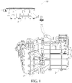
FIG. 1 , a transmission 1' and anelectric motor 2' are designed separately and fixed by a mold assembly bolt to form the powertrain 10' mounted on a frame by suspension. Acontroller 3 is arranged separately from theelectric motor 2' and is mounted on the frame above theelectric motor 2' and the transmission 1'. A controller signal is transmitted to theelectric motor 2' through a three-phase wire for controlling operation of the powertrain 10'. - In such form of powertrain, the controller 3' is arranged separately and is mounted on the frame above the transmission 1' and the
electric motor 2', occupying a large space of an entire vehicle. In addition, a height of the powertrain cannot meet requirements of a rear drive of the entire vehicle, and a wire harness such as the three-phase wire is relatively long, occupying a large space of the entire vehicle, affecting the appearance, and requiring a high protection level. - The present disclosure is intended to resolve at least one of technical problems existing in the prior art. Accordingly, the present disclosure provides a powertrain. The powertrain is characterized with advantages of a compact structure and simple wire harness connection.
- The present disclosure further provides a vehicle including the powertrain.
- A powertrain provided according to an embodiment in a first aspect of the present disclosure includes: an electric motor; a transmission mounted to the electric motor and defining, together with the electric motor, an angled space for helping a half shaft of the transmission to extend along an axial direction of the transmission; a controller mounted to at least one of the electric motor and the transmission and electrically connected to the electric motor; where the controller, the transmission, and the electric motor are integrated together, at least one part of the controller being located in the angled space.
- For the powertrain according to the embodiments of the present disclosure, the controller, the transmission, and the electric motor are integrated together, and the controller is mounted in the angled space defined between the transmission and the electric motor, so that the powertrain is characterized with advantages of a compact structure and simple wire harness connection, etc.
- Other aspects and advantages of the present disclosure will be given in the following description, some of which will become apparent from the following description or may be learned from practices of the present disclosure.
- The foregoing and/or additional aspects and advantages of the present disclosure will become apparent and comprehensible in the description made with reference to the following accompanying drawings, where:
-
FIG. 1 is a schematic structural view of a powertrain system in the related art; -
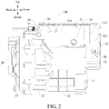
FIG. 2 is a side view of a powertrain according to an embodiment of the present disclosure; -
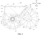
FIG. 3 is a front view of a powertrain according to an embodiment of the present disclosure; -
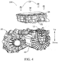
FIG. 4 is a schematic view of electric connection between a controller and an electric motor of a powertrain according to an embodiment of the present disclosure; -
FIG. 5 is a three-dimensional view of a powertrain according to an embodiment of the present disclosure; -
FIG. 6 is a schematic structural view of an electric motor case body and a front transmission case body of a powertrain according to an embodiment of the present disclosure; -
FIG. 7 is a schematic structural view of an electric motor case body and a front transmission case body of a powertrain according to another embodiment of the present disclosure; and -
FIG. 8 is a schematic view of a vehicle according to an embodiment of the present disclosure. - The following describes embodiments of the present disclosure in detail. Examples of the embodiments are shown in the accompanying drawings, and same or similar reference signs in all the accompanying drawings indicate same or similar components or components having same or similar functions. The embodiments described below with reference to the accompanying drawings are exemplary, and are intended to explain the present disclosure and cannot be construed as a limitation to the present disclosure.
- In the description of the present disclosure, it should be understood that orientation or position relationships indicated by the terms such as "center", "vertical", "horizontal", "length", "width", "above", "below", "front", "rear", "left", "right", "vertical", "horizontal", "top", "bottom", "inside", "outside", "axial", "radial", and "circumferential" are based on orientation or position relationships shown in the accompanying drawings, and are used only for ease and brevity of illustration and description, rather than indicating or implying that the mentioned apparatus or component must have a particular orientation or must be constructed and operated in a particular orientation. Therefore, such terms should not be construed as limiting of the present disclosure. In addition, a feature defined to be "first" or "second" may explicitly or implicitly include one or more features. In the description of the present disclosure, unless stated otherwise, the meaning of "a plurality of" is two or more than two.
- In the description of the present disclosure, it should be noted that unless otherwise explicitly specified or defined, the terms such as "mount", "install", "connect", and "connection" should be understood in a broad sense. For example, the connection may be a fixed connection, a detachable connection, or an integral connection; or the connection may be a mechanical connection or an electrical connection; or the connection may be a direct connection, an indirect connection through an intermediary, or internal communication between two components. Persons of ordinary skill in the art may understand the specific meanings of the foregoing terms in the present disclosure according to specific situations.
- A
powertrain 100 according to an embodiment of the present disclosure is described below with reference toFIG. 2 to FIG. 7 . - As shown in
FIG. 2 to FIG. 5 , thepowertrain 100 according to an embodiment of the present disclosure includes: anelectric motor 10, atransmission 20, and acontroller 30. - The
transmission 20 is mounted to theelectric motor 10, and thetransmission 20 is mounted on theelectric motor 10. Thetransmission 20 and theelectric motor 10 jointly define anangled space 40 for helping a half shaft (not shown) of the transmission to extend in an axial direction of the transmission. Thecontroller 30, thetransmission 20, and theelectric motor 10 are integrated together. At least one part of thecontroller 30 is located in theangled space 40. In particular, theelectric motor 10 is mounted on one side of thetransmission 20 in a horizontal direction. A transmission shaft (not shown) of thetransmission 20 is connected to theelectric motor 10. The half shaft of thetransmission 20 is mounted to theelectric motor 10 and is on the same side as thetransmission 20, and the half shaft of thetransmission 20 is parallel to the axial direction of theelectric motor 10. Theangled space 40 is defined by theelectric motor 10 and thetransmission 20. Theangled space 40 is located on a side of theelectric motor 10 facing the half shaft of thetransmission 20, and theangled space 40 is located on a side of thetransmission 20 facing theelectric motor 10. In other words, theangled space 40 respectively abuts against the side of theelectric motor 10 facing thetransmission 20 and the side of thetransmission 20 facing theelectric motor 10. - It may be understood that an angle of the angled space enclosed by the
electric motor 10 and thetransmission 20 is less than 180 degrees. - The
controller 30 is mounted to at least one of theelectric motor 10 and thetransmission 20 and is electrically connected to theelectric motor 10. Thecontroller 30, thetransmission 20, and theelectric motor 10 are integrated together. Thecontroller 30 includes a controller body and acontroller support 31 located in theangled space 40. - In the embodiment shown in
FIG. 2 to FIG. 5 , theelectric motor 10 is mounted on both theelectric motor 10 and thetransmission 20. Thecontroller 30 is electrically connected to theelectric motor 10. Thecontroller 30 is configured to control start, stop, and a rotation speed, etc. of theelectric motor 10. The controller body is disposed in theangled space 40. It may be understood that the controller body refers to a function bearing part of thecontroller 30, that is, a part for achieving a control function, and does not include parts such as a mounted support. Thecontroller 30 and theelectric motor 10 are disposed on the same side of thetransmission 20, and thecontroller 30 and the half shaft of thetransmission 20 are disposed on the same side of theelectric motor 10. That thecontroller 30, thetransmission 20, and theelectric motor 10 are integrated together refers to that thecontroller 30, thetransmission 20, and theelectric motor 10 form a unity in a structural space. It may be understood that theelectric motor 10 not only may be mounted on thecontroller 30 and thetransmission 20, but also may be mounted on thecontroller 30 only, or on thetransmission 20 only. - For the
powertrain 100 according to an embodiment of the present disclosure, theangled space 40 is defined between thetransmission 20 and theelectric motor 10, and thecontroller 30, thetransmission 20, and theelectric motor 10 are integrated together, so that thepowertrain 100 has a compact structure. Thecontroller 30 is mounted on thetransmission 20 and theelectric motor 10. A three-phase wire connected between thecontroller 30 and theelectric motor 10 is relatively short, and there is no need to dispose a relatively long connecting wire harness, saving a mounting space and causingpowertrain 100 to be simple and beautiful as a whole. In addition, mounting points of thecontroller 30 on the frame are reduced, an entire vehicle structure is simplified, assembly procedures are reduced, production costs and development costs are reduced, and the center of gravity of thepowertrain 100 is lowered, so that the powertrain may be applied to a front-drive vehicle and a rear-drive vehicle. - In addition, because the controller body is disposed in the angled
space 40, space of the angledspace 40 may be utilized to move thecontroller 30 downward into the angledspace 40, thereby reducing an overall height of thepowertrain 100. - Therefore, the
powertrain 100 according to the embodiment of the present disclosure is characterized with advantages of a compact structure and simple wire harness connection, etc. - The
powertrain 100 according to the embodiments of the present disclosure is described in detail below with reference toFIG. 2 to FIG. 7 . - In some embodiments of the present disclosure, as shown in
FIG. 3 , a lowest point of the controller body is lower than a highest point of theelectric motor 10 and/or a highest point of thetransmission 20. When the highest point of theelectric motor 10 is lower than the highest point of thetransmission 20, the lowest point of thecontroller 30 is lower than the highest point of thetransmission 20. When the highest point of theelectric motor 10 is higher than the highest point of thetransmission 20, the lowest point of thecontroller 30 is lower than the highest point of theelectric motor 10. When the highest point of theelectric motor 10 is at an equal height with the highest point of thetransmission 20, the lowest point of thecontroller 30 is lower than the highest point of theelectric motor 10 and the highest point of thetransmission 20. - In particular, the lowest point and the highest point are located at a direction perpendicular to a horizontal plane, that is, an up-down direction shown in
FIG. 5 . The lowest point of thecontroller 30 is the lowest point of thecontroller 30 in the up-down direction. The highest point of theelectric motor 10 is the highest point of theelectric motor 10 in the up-down direction. The highest point of thetransmission 20 is the highest point of thetransmission 20 in the up-down direction. The lowest point of thecontroller 30 is lower than the highest point of theelectric motor 10 and/or the highest point of thetransmission 20. Accordingly, a height of the unity formed by thecontroller 30, theelectric motor 10, and thetransmission 20 in the up-down direction shown inFIG. 3 is the smallest, so that an overall structure formed by thecontroller 30, theelectric motor 10, and thetransmission 20 is more compact and occupies a smaller space. - In some embodiments of the present disclosure, as shown in
FIG. 2 to FIG. 5 , thecontroller 30 is mounted above the half shaft. In a specific embodiment of the present disclosure, as shown inFIG. 4 , thecontroller 30 has a mountinggroove 34. - Optionally, the mounting
groove 34 is disposed on a side of thecontroller 30, and a part of theelectric motor 10 is inserted into the mountinggroove 34 from a bottom of the mountinggroove 34. For example, in an embodiment shown inFIG. 4 , the mountinggroove 34 may be disposed on afourth side surface 312, and the mountinggroove 34 is open toward one side. In addition, a side wall at a bottom of the mountinggroove 34 has a through hole. Theelectric motor 10 is partially inserted into the mountinggroove 34 from the bottom of the mountinggroove 34, so that theelectric motor 10 and thecontroller 30 are detachably connected. - Further, still referring to the embodiment shown in
FIG. 4 , thecontroller 30 includes a controller three-phasewire connection portion 35. The controller three-phasewire connection portion 35 is located in the mountinggroove 34. Theelectric motor 10 includes an electric motor three-phasewire connection portion 12. The controller three-phasewire connection portion 35 is electrically connected to the electric motor three-phasewire connection portion 12. During assembly, thecontroller 30 may be mounted on a top of theelectric motor 10, and then the electric motor three-phasewire connection portion 12 is extended into the mountinggroove 34, so that the controller three-phasewire connection portion 35 is electrically connected to the electric motor three-phasewire connection portion 35. - According to an embodiment of the present disclosure, as shown in
FIG. 4 , the controller three-phasewire connection portion 35 is docked with the electric motor three-phasewire connection portion 12 and connected to the electric motor three-phase wire connection portion through a connectingmember 13. The connectingmember 13 may be a conductive bolt or a conductive sheet provided with an inserting hole. Accordingly, an electrical connection between thecontroller 30 and theelectric motor 10 has a simple structure and is easy to assemble and disassemble. - The
controller 30 is described in detail below with reference toFIG. 2 to FIG. 5 . - According to an embodiment of the present disclosure, the
controller 30 includes: a controller body, acontroller support 31, and awire harness rack 32. - The controller body is disposed on the
controller support 31. Thecontroller support 31 is mounted on at least one of theelectric motor 10 and thetransmission 20. Thewire harness rack 32 is mounted on thecontroller support 31 and theelectric motor 10. Awire arrangement groove 321 is disposed in thewire harness rack 32. The connecting wire harness between thecontroller 30 and theelectric motor 10 is disposed in thewire arrangement groove 321. - In particular, the controller body is disposed on the
controller support 31. As shown inFIG. 2 to FIG. 5 , thecontroller support 31 is a housing. The controller body may be disposed in the controller support 31.Thecontroller support 31 may be mounted on theelectric motor 10 or thetransmission 20, or mounted on both theelectric motor 10 and thetransmission 20. In an embodiment shown inFIG. 2 to FIG. 4 , thecontroller support 31 is mounted on both theelectric motor 10 and thetransmission 20, thewire harness rack 32 is mounted on thecontroller support 31 and theelectric motor 10, and thewire arrangement groove 321 is in communication with theelectric motor 10 and thecontroller support 31, and thewire arrangement groove 321 is configured to accommodate a connecting wire harness of thecontroller 30 and theelectric motor 10. Accordingly, thewire arrangement groove 321 serves to accommodate and protect the connecting wire harness, thereby causing thepowertrain 100 to be entirely simple and beautiful. According to some other embodiments of the present disclosure, thecontroller support 31 may also be an open fixing support. The controller body is fixed on thecontroller support 31. - Optionally, as shown in
FIG. 2 andFIG. 5 , thewire harness rack 32 and thetransmission 20 are respectively located on two opposite sides of theelectric motor 10 in a horizontal direction. In other words, thewire harness rack 32 and thetransmission 20 are respectively disposed on two opposite sides of theelectric motor 10 in an axial direction of theelectric motor 10. As shown inFIG. 4 , thewire harness rack 32 is disposed on a front side of theelectric motor 10 in the horizontal direction, and thetransmission 20 is disposed on a rear side of theelectric motor 10 in the horizontal direction. - Still referring to the embodiment shown in
FIG. 3 andFIG. 5 , thewire harness rack 32 extends obliquely relative to an up-down direction and along a radial direction of theelectric motor 10. In particular, a cross section of theelectric motor 10 along an axial direction thereof is circular, and thewire harness rack 32 is disposed on an end surface of theelectric motor 10. Thewire harness rack 32 extends obliquely from a center of a circle of the cross section of theelectric motor 10 along a radial direction of theelectric motor 10 to a left side of the entireelectric motor 10. - Further, the
controller support 31, theelectric motor 10, and thetransmission 20 are mounted through threadedfasteners 50, and thewire harness rack 32 and theelectric motor 10 are mounted through the threadedfasteners 50. The threadedfasteners 50 may be bolts. Screw holes are disposed on theelectric motor 10 and thetransmission 20. The bolts pass through thecontroller support 31 and thewire harness rack 32 to be inserted into screw holes with internal threads on theelectric motor 10 and thetransmission 20. Accordingly, fixing between thecontroller support 31, theelectric motor 10, and thetransmission 20, and between thewire harness rack 32 and theelectric motor 10 through the threadedfasteners 50 are effective, and mounting is convenient. - Still referring to the embodiment shown in
FIG. 2 to FIG. 5 , the threadedfastener 50 mounted on theelectric motor 10 extend obliquely relative to the up-down direction and along a radial direction of theelectric motor 10, and the threadedfasteners 50 mounted on thetransmission 20 extend obliquely relative to the up-down direction and along a radial direction of thetransmission 20. The radial direction of theelectric motor 10 refers to a direction in which a straight line passes through the center of the circle in the cross section of theelectric motor 10, and the radial direction of thetransmission 20 refers to a direction in which a straight line passes through a center of a transmission shaft of thetransmission 20. - Optionally, the
controller support 31 includes a first mountingtongue 51, and thewire harness rack 32 includes a second mountingtongue 52. The threadedfasteners 50 are disposed on the first mountingtongue 51 and the second mountingtongue 52. - In particular, the first mounting
tongue 51 connected to thetransmission 20 extends along a tangential direction of thetransmission 20 in a width direction of the first mounting tongue, and extends along a radial direction of thetransmission 20 in a length direction of the first mounting tongue. The first mountingtongue 51 and the second mountingtongue 52 connected to theelectric motor 10 extend in a tangential direction of theelectric motor 10 in width directions of the first mounting tongue and the second mounting tongue and extend along a radial direction of theelectric motor 10 in length directions of the first mounting tongue and the second mounting tongue. The first mountingtongue 51 serves to increase a force bearing area of thecontroller support 31, thetransmission 20, and theelectric motor 10. Similarly, the second mountingtongue 52 serves to increase a force bearing area of thewire harness rack 32 and theelectric motor 10. Accordingly, the threadedfasteners 50 achieve a better effect of fixing and have a higher structural stability. - Further, mounting
studs 53 are respectively disposed on theelectric motor 10 and thetransmission 20, the mountingstuds 53 having internal threads matching the threadedfasteners 50. The mountingstuds 53 are disposed corresponding to the first mountingtongue 51 and the second mountingtongue 52. The threadedfasteners 50 extend through the first mountingtongue 51 and the second mountingtongue 52 into the mountingstuds 53 and fit internal threads of the mountingstuds 53. Accordingly, threaded connection between the threadedfasteners 50 and theelectric motor 10 and thetransmission 20 may be more stable, and the mountingstuds 53 may serve to protect the threadedfasteners 50. - According to a further embodiment of the present disclosure, as shown in
FIG. 5 , there are a plurality of first mountingtongues 51 distributed at intervals along a circumferential direction of thecontroller support 31. Threadedfasteners 50 are disposed on each of the first mountingtongues 51. The circumferential direction of thecontroller support 31 refers to a direction toward a periphery of thecontroller support 31 when thecontroller support 31 is viewed from the top in a vertical direction. The plurality of first mountingtongues 51 are disposed on a side wall of thecontroller support 31 and are spaced apart. Accordingly, the configuration of the plurality of first mountingtongues 51 provides a better effect of fixing betweencontroller support 31, theelectric motor 10, and thetransmission 20. - Still referring to the embodiment shown in
FIG. 2 andFIG. 5 , asignal line connector 33 is disposed on one side surface of thecontroller support 31. Thewire harness rack 32 is mounted on the other side surface of thecontroller support 31. Each of remaining side surfaces of thecontroller support 31 except the two side surfaces has at least one of the first mountingtongues 51. - A
signal line connector 33 is disposed on a side surface of thecontroller support 31 far away from theelectric motor 10. Thesignal line connector 33 is configured to connect a signal line to thecontroller 30. Awire harness rack 32 is mounted on a side surface of thecontroller support 31 far away from thetransmission 20. The two side surfaces intersect with each other. At least one first mountingtongue 51 is disposed on each of two side surfaces opposite to the two side surfaces. - Further, the
controller support 31 has afirst side surface 311, a second side surface, a third side surface, and afourth side surface 312 connected in sequence along a circumferential direction of thecontroller support 31. Thefirst side surface 311, the second side surface, the third side surface, and the fourth side surface are arranged clockwise along a circumferential direction of thecontroller support 31. - As shown in
FIG. 2 to FIG. 5 , thefirst side surface 311 is a side surface located on a left side of thecontroller support 31, the second side surface is a side surface located on a rear side of thecontroller support 31, the third side surface is a side surface located on a right side of thecontroller support 31, and the fourside surface 312 is a side surface located on a front side of thecontroller support 31. - The
signal line connector 33 is disposed on thefirst side surface 311, the second side surface faces thetransmission 20, the third side surface faces theelectric motor 10, and thewire harness rack 32 is mounted on thefourth side surface 312. One first mountingtongue 51 is disposed on the second side surface. The first mountingtongue 51 is located at an end of the second side surface adjacent to thefirst side surface 311. Two of the first mountingtongues 51 are disposed on the third side surface, and the two first mountingtongues 51 are respectively adjacent to two ends of the third side surface. - Further, as shown in
FIG. 5 , the first mountingtongue 51 on the second side surface is mounted to thetransmission 20 through the threadedfasteners 50, and the remaining first mountingtongues 51 and a second mountingtongue 52 are respectively mounted to theelectric motor 10 through the threadedfasteners 50. - In some embodiments of the present disclosure, as shown in
FIG. 5 to FIG. 7 , theelectric motor 10 includes an electricmotor case body 11. Thetransmission 20 includes a fronttransmission case body 21 and a reartransmission case body 22. The fronttransmission case body 21 is connected to the electricmotor case body 11. The reartransmission case body 22 is disposed away from the electricmotor case body 11. The angledspace 40 is defined by the electricmotor case body 11 and the fronttransmission case body 21. Thecontroller 30 is mounted to the electricmotor case body 11 and the fronttransmission case body 21. - In one embodiment of the present disclosure, as shown in
FIG. 6 , the electricmotor case body 11 and the fronttransmission case body 21 are both separate pieces and assembled together. In other words, the electricmotor case body 11 and the fronttransmission case body 21 are separately manufactured and then assembled together. - In another embodiment of the present disclosure, as shown in
FIG. 7 , the electricmotor case body 11 and the fronttransmission case body 21 are an integral piece. In other words, the electricmotor case body 11 and the fronttransmission case body 21 may be manufactured by integral molding. Accordingly, an overall structure formed by the electricmotor case body 11 and the fronttransmission case body 21 has better stability and is conveniently processed and manufactured, omitting a procedure of assembled mounting. - A
vehicle 1000 according to an embodiment of the present disclosure is described below with reference toFIG. 8 . - As shown in
FIG. 8 , thevehicle 1000 according to the embodiment of the present disclosure includes thepowertrain 100 according to the foregoing embodiments of the present disclosure. - For the
vehicle 1000 according to the embodiment of the present disclosure, thepowertrain 100 according to the foregoing embodiment of the present disclosure is used, reducing the layout space of the entire vehicle, simplifying the wire harness connection and protection, simplifying the structure of the entire vehicle, and reducing assembly procedures. - In one embodiment of the present disclosure, the
powertrain 100 includes anelectric motor 10, atransmission 20, and acontroller 30. - The
electric motor 10 includes an electricmotor case body 11. Thetransmission 20 is transmissibly connected to theelectric motor 10, and thetransmission 20 includes a transmission case body. The electricmotor case body 11 and the transmission case body are integrated into an entire case body, and the electricmotor case body 11 and the transmission case body define anangled space 40 for helping a half shaft of the transmission to extend along an axial direction of the transmission. Thecontroller 30 is electrically connected to theelectric motor 10, and thecontroller 30 is mounted in at least one of the electricmotor case body 11 and the transmission case body in the angledspace 40. In other words, thecontroller 30 may be mounted to the electricmotor case body 11 in the angledspace 40 or to the transmission case body, or mounted to both the electricmotor case body 11 and the transmission case body. - For the
powertrain 100 according to the embodiment of the present disclosure, the electricmotor case body 11 and the transmission case body are integrated into one entire case body to simplify an entire structure of thepowertrain 100, and reduce assembly procedures, requiring no long wire harness connected between thecontroller 30 and theelectric motor 10 and simplifying wire harness connection and protection. In addition, thecontroller 30 is mounted to at least one of the electricmotor case body 11 and the transmission case body in the angledspace 40 to cause a mounting space of thepowertrain 100 to be smaller and a structure to be more compact. - Other compositions and operations of the
powertrain 100 and thevehicle 1000 including the powertrain according to the embodiments of the present disclosure are known to those of ordinary skill in the art, and are not described herein again in detail. - In the description of this specification, the description of the reference terms such as "an embodiment", "some embodiments", "exemplary embodiments", "example", "specific example", or "some examples" means that the specific features, structures, materials or characteristics described with reference to the embodiment or example are included in at least one embodiment or example of the present disclosure. In this specification, schematic descriptions of the foregoing terms do not necessarily directed at a same embodiment or example. Moreover, the specific features, structures, materials, or characteristics described may be combined in any one or more embodiments or examples in an appropriate manner.
- Although the embodiments of the present disclosure have been shown and described, persons of ordinary skill in the art should understand that various changes, modifications, replacements and variations may be made to the embodiments without departing from the principles and spirit of the present disclosure, and the scope of the present disclosure is as defined by the appended claims and their equivalents.
Claims (23)
- A powertrain (100), comprising:an electric motor (10);a transmission (20) mounted to the electric motor (10) and defining, together with the electric motor (10), an angled space (40) for helping a half shaft of the transmission extend along an axial direction of the transmission; anda controller (30) mounted to at least one of the electric motor (10) and the transmission (20) and electrically connected to the electric motor (10); whereinthe controller (30), the transmission (20), and the electric motor (10) are integrated together, at least one part of the controller (30) being located in the angled space (40).
- The powertrain (100) according to claim 1, wherein a lowest point of the controller (30) is lower than a highest point of the electric motor (10) and/or a highest point of the transmission (20).
- The powertrain (100) according to claim 1, wherein the controller (30) is mounted above the half shaft.
- The powertrain (100) according to claim 1, wherein the controller (30) has a mounting groove (34).
- The powertrain (100) according to claim 4, wherein the mounting groove (34) is disposed on a side of the controller (30).
- The powertrain (100) according to claim 5, wherein the controller (30) comprises a controller three-phase wire connection portion (35) located in the mounting groove (34), and the electric motor (10) comprises an electric motor three-phase wire connection portion (12), the electric motor three-phase wire connection portion (12) extending into the mounting groove (34) and being electrically connected to the controller three-phase wire connection portion (35).
- The powertrain (100) according to claim 6, wherein the controller three-phase wire connection portion (35) is docked with the electric motor three-phase wire connection portion (12) and connected to the electric motor three-phase wire connection portion through a connecting member.
- The powertrain (100) according to claim 1, wherein the controller (30) comprises:a controller body;a controller support (31), the controller body being disposed on the controller support (31), and the controller support (31) being mounted to at least one of the electric motor (10) and the transmission (20); anda wire harness rack (32) mounted to the controller support (31) and the electric motor (10) and having a wire arrangement groove (321), a connecting wire harness between the controller (30) and the electric motor (10) being disposed in the wire arrangement groove (321).
- The powertrain (100) according to claim 8, wherein the wire harness rack (32) and the transmission (20) are respectively located on two opposite sides of the electric motor (10) in a horizontal direction.
- The powertrain (100) according to claim 8, wherein the wire harness rack (32) extends obliquely relative to an up-down direction and along a radial direction of the electric motor (10).
- The powertrain (100) according to claim 8, wherein the controller support (31), the electric motor (10), and the transmission (20), and the wire harness rack (32) and the electric motor (10) are mounted through threaded fasteners (50).
- The powertrain (100) according to claim 11, wherein the threaded fasteners (50) mounted to the electric motor (10) extend obliquely relative to an up-down direction and along a radial direction of the electric motor (10); and
the threaded fasteners (50) mounted to the transmission (20) extend obliquely relative to the up-down direction and along a radial direction of the transmission (20). - The powertrain (100) according to claim 11, wherein the controller support (31) comprises a first mounting tongue (51) and the wire harness rack (32) comprises a second mounting tongue (52), the threaded fasteners (50) being disposed on the first mounting tongue (51) and the second mounting tongue (52).
- The powertrain (100) according to claim 11, wherein mounting studs (53) are respectively disposed on the electric motor (10) and the transmission (20), the mounting studs (53) having internal threads matching the threaded fasteners (50).
- The powertrain (100) according to claim 14, wherein there are a plurality of first mounting tongues (51) distributed at intervals along a circumferential direction of the controller support (31), the threaded fastener (50) being disposed on each of the first mounting tongues (51).
- The powertrain (100) according to claim 15, wherein a signal line connector (33) is disposed on one side surface of the controller support (31), the wire harness rack (32) being mounted on the other side surface of the controller support (31), each of remaining side surfaces of the controller support (31) except the two side surfaces having at least one of the first mounting tongues (51).
- The powertrain (100) according to claim 16, wherein the controller support (31) has a first side surface (311), a second side surface, a third side surface, and a fourth side surface (312) connected in sequence along the circumferential direction of the controller support (31), the signal line connector (33) being disposed on the first side surface (311), the second side surface facing the transmission (20), the third side surface facing the electric motor (10), and the wire harness rack (32) being mounted on the fourth side surface (312);
one first mounting tongue (51) being disposed on the second side surface, and the first mounting tongue (51) being located at one end of the second side surface adjacent to the first side surface (311); and
two of the first mounting tongues (51) being disposed on the third side surface and the two first mounting tongues (51) being respectively adjacent to two ends of the third side surface. - The powertrain (100) according to claim 17, wherein the first mounting tongue (51) on the second side surface is mounted to the transmission (20) through the threaded fasteners (50), and the remaining first mounting tongues (51) and a second mounting tongue (52) are respectively mounted to the electric motor (10) through the threaded fasteners (50).
- The powertrain (100) according to any of claims 1 to 18, wherein the electric motor (10) comprises an electric motor case body (11), and the transmission (20) comprises a front transmission case body (21) and a rear transmission case body (22), the angled space (40) being defined by the electric motor case body (11) and the front transmission case body (21), and the controller (30) being mounted to the electric motor case body (11) and the front transmission case body (21).
- The powertrain (100) according to claim 19, wherein the electric motor case body (11) and the front transmission case body (21) are both separate pieces and assembled together.
- The powertrain (100) according to claim 19, wherein the electric motor case body (11) and the front transmission case body (21) are an integral piece.
- A vehicle (1000), comprising the powertrain (100) according to any of claims 1 to 21.
- A powertrain (100), comprising:an electric motor (10) comprising an electric motor case body (11);a transmission (20) connected to the electric motor (10) in a transmission manner and comprising a transmission case body; the electric motor case body (11) and the transmission case body being integrated into an entire case body, and the electric motor case body (11) and the transmission case body defining an angled space (40) for helping a half shaft of the transmission to extend along an axial direction of the transmission; anda controller (30) electrically connected to the electric motor (10) and mounted to at least one of the electric motor case body (11) and the transmission case body in the angled space (40).
Applications Claiming Priority (2)
| Application Number | Priority Date | Filing Date | Title |
|---|---|---|---|
| CN201810145468.8A CN110154715B (en) | 2018-02-12 | 2018-02-12 | Powertrain and vehicle having the same |
| PCT/CN2019/073568 WO2019154164A1 (en) | 2018-02-12 | 2019-01-29 | Powertrain and vehicle provided with same |
Publications (2)
| Publication Number | Publication Date |
|---|---|
| EP3750730A1 true EP3750730A1 (en) | 2020-12-16 |
| EP3750730A4 EP3750730A4 (en) | 2021-04-14 |
Family
ID=67549224
Family Applications (1)
| Application Number | Title | Priority Date | Filing Date |
|---|---|---|---|
| EP19751819.4A Pending EP3750730A4 (en) | 2018-02-12 | 2019-01-29 | DRIVELINE AND VEHICLE WITH IT |
Country Status (5)
| Country | Link |
|---|---|
| US (3) | US11919386B2 (en) |
| EP (1) | EP3750730A4 (en) |
| CN (1) | CN110154715B (en) |
| DE (1) | DE202019006143U1 (en) |
| WO (1) | WO2019154164A1 (en) |
Families Citing this family (8)
| Publication number | Priority date | Publication date | Assignee | Title |
|---|---|---|---|---|
| CN110154715B (en) * | 2018-02-12 | 2021-10-22 | 比亚迪股份有限公司 | Powertrain and vehicle having the same |
| CN112440705B (en) * | 2019-08-30 | 2022-08-09 | 比亚迪股份有限公司 | Power assembly |
| JP7204623B2 (en) | 2019-09-20 | 2023-01-16 | 日立Astemo株式会社 | Electromechanical Integrated Power Conversion Device and Drive Device for Electric Vehicle |
| CN113572314B (en) * | 2020-04-29 | 2022-10-18 | 比亚迪股份有限公司 | Multifunctional controller and power assembly |
| JP7435313B2 (en) * | 2020-07-01 | 2024-02-21 | マツダ株式会社 | vehicle |
| JP7677302B2 (en) * | 2022-10-12 | 2025-05-15 | トヨタ自動車株式会社 | Vehicle drive device |
| EP4647280A4 (en) * | 2023-01-05 | 2026-04-22 | Byd Co Ltd | DRIVETRAIN HOUSING BODY, DRIVETRAIN AND VEHICLE |
| WO2024146441A1 (en) * | 2023-01-05 | 2024-07-11 | 比亚迪股份有限公司 | Power assembly and vehicle having same |
Family Cites Families (68)
| Publication number | Priority date | Publication date | Assignee | Title |
|---|---|---|---|---|
| US6725833B1 (en) * | 1999-03-29 | 2004-04-27 | Hitachi, Ltd. | Electronically controlled throttle device |
| JP3882994B2 (en) | 2001-12-27 | 2007-02-21 | アイシン・エィ・ダブリュ株式会社 | Motor control unit cooling device |
| JP4096858B2 (en) | 2002-10-23 | 2008-06-04 | 日産自動車株式会社 | Cooling device for electric motor for vehicle |
| JP3815456B2 (en) | 2003-04-09 | 2006-08-30 | トヨタ自動車株式会社 | Arrangement structure of high-voltage wires in hybrid vehicles |
| US7586225B2 (en) | 2004-03-22 | 2009-09-08 | Gm Global Technology Operations, Inc. | Hybrid transmission motor module with integral wire connections |
| US7129595B2 (en) | 2004-03-22 | 2006-10-31 | General Motors Corporation | Hybrid electro-mechanical vehicular transmission having multiple modular motor/generators assembled from like components |
| WO2006035982A2 (en) | 2004-09-27 | 2006-04-06 | Toyota Jidosha Kabushiki Kaisha | Drive apparatus for vehicle |
| JP5328231B2 (en) | 2008-06-12 | 2013-10-30 | 本田技研工業株式会社 | Vehicle drive motor unit |
| DE102009014595A1 (en) | 2009-03-24 | 2010-09-30 | Magna Powertrain Ag & Co Kg | gear unit |
| US8696326B2 (en) * | 2009-05-14 | 2014-04-15 | Magna Powertrain Inc. | Integrated electrical auxiliary oil pump |
| CN201619446U (en) * | 2009-12-30 | 2010-11-03 | 四川东风电机厂有限公司 | Vehicle pure electric power assembly integrated device |
| CN201824898U (en) * | 2010-08-30 | 2011-05-11 | 天津市松正电动科技有限公司 | Integrated motor and controller assembly |
| JP5581922B2 (en) | 2010-09-10 | 2014-09-03 | アイシン精機株式会社 | Hybrid vehicle drive device and case |
| CN102463880B (en) * | 2010-11-16 | 2014-04-16 | 一汽海马汽车有限公司 | Front cabin assembly of pure electric automobile and installation bracket |
| US9103646B2 (en) * | 2010-12-21 | 2015-08-11 | Bradford W. Bur | Active fuel management systems and methods for vehicles with a manual transmission |
| CN103339839B (en) | 2011-01-31 | 2015-12-09 | 丰田自动车株式会社 | The carrying structure of power control unit |
| CN102267362A (en) * | 2011-05-13 | 2011-12-07 | 东方电气集团东风电机有限公司 | Integrated structure of electric vehicle drive |
| CN202274066U (en) | 2011-09-28 | 2012-06-13 | 重庆长安汽车股份有限公司 | Electric automobile reduction case |
| CN103874870A (en) | 2011-10-14 | 2014-06-18 | 丰田自动车株式会社 | Power transmission device |
| WO2013069774A1 (en) | 2011-11-09 | 2013-05-16 | 日立オートモティブシステムズ株式会社 | Drive device for electric automobile |
| DE102012004287A1 (en) | 2012-03-01 | 2013-09-05 | Brose Fahrzeugteile GmbH & Co. Kommanditgesellschaft, Würzburg | electric motor |
| US9435324B2 (en) * | 2012-05-10 | 2016-09-06 | Parker-Hannifin Corporation | Electro-hydraulic drive system |
| CN202629021U (en) | 2012-06-12 | 2012-12-26 | 南京高精齿轮集团有限公司 | Main transmission gear box for driving cold-rolling crimping machine |
| DE102012013947A1 (en) | 2012-07-12 | 2014-01-16 | Brose Fahrzeugteile GmbH & Co. Kommanditgesellschaft, Würzburg | gear unit |
| CN102774279B (en) | 2012-07-25 | 2015-10-28 | 襄阳宇清传动科技有限公司 | Irredundant fulcrum type motor and speed changer integrated drive system |
| JP5862502B2 (en) * | 2012-07-27 | 2016-02-16 | アイシン・エィ・ダブリュ株式会社 | Vehicle drive device |
| US9391496B2 (en) * | 2013-01-18 | 2016-07-12 | GM Global Technology Operations LLC | Transmission for a vehicle |
| US20140202279A1 (en) | 2013-01-18 | 2014-07-24 | GM Global Technology Operations LLC | Transmission for a vehicle |
| JP5939351B2 (en) | 2013-02-15 | 2016-06-22 | 日産自動車株式会社 | Cooling device for motor drive unit |
| CN104070980B (en) * | 2013-03-28 | 2017-02-08 | 比亚迪股份有限公司 | Integrated hybrid power assembly body and car with same |
| CN203222035U (en) * | 2013-04-16 | 2013-10-02 | 比亚迪股份有限公司 | Hybrid power vehicle and front cabin thereof |
| JP5951553B2 (en) | 2013-04-26 | 2016-07-13 | 三菱重工オートモーティブサーマルシステムズ株式会社 | Inverter-integrated electric compressor |
| DE112014001112T5 (en) | 2013-05-31 | 2015-12-24 | Aisin Aw Co., Ltd. | Vehicle drive device |
| JP6080207B2 (en) | 2013-06-18 | 2017-02-15 | 本田技研工業株式会社 | Power transmission device for vehicle |
| JP2015021525A (en) | 2013-07-17 | 2015-02-02 | Ntn株式会社 | In-wheel motor drive unit |
| CN106163848A (en) * | 2014-01-21 | 2016-11-23 | 互动的全电动汽车有限责任公司 | Electric power promotes vehicle |
| CN103795183B (en) | 2014-03-06 | 2016-08-17 | 北汽大洋电机科技有限公司 | Power assembly system |
| CN103825404B (en) | 2014-03-25 | 2016-07-06 | 北汽大洋电机科技有限公司 | Motor and variator integrated cooling system |
| JP6332450B2 (en) | 2014-07-10 | 2018-05-30 | 日産自動車株式会社 | Power unit |
| JP6303957B2 (en) | 2014-09-26 | 2018-04-04 | 株式会社デンソー | Drive device |
| CN105827060A (en) | 2015-01-08 | 2016-08-03 | 大陆汽车投资(上海)有限公司 | integrated electric drive system |
| JP6645739B2 (en) | 2015-01-28 | 2020-02-14 | 本田技研工業株式会社 | Integrated unit |
| US10675962B2 (en) | 2015-01-28 | 2020-06-09 | Honda Motor Co., Ltd. | Hybrid vehicle driving system |
| JP2016176501A (en) | 2015-03-19 | 2016-10-06 | Ntn株式会社 | Wheel drive unit |
| JP6634581B2 (en) * | 2015-09-07 | 2020-01-22 | 株式会社テージーケー | Motor actuator, method of processing motor actuator, and method of inspecting motor actuator |
| CN106608169B (en) * | 2016-01-20 | 2023-10-27 | 东莞中汽宏远汽车有限公司 | Direct drive pure electric power unit |
| CN205736909U (en) | 2016-06-03 | 2016-11-30 | 东风汽车公司 | A kind of plug-in hybrid-power automobile engine room arrangement structure |
| CN205836565U (en) * | 2016-06-16 | 2016-12-28 | 北京长城华冠汽车科技股份有限公司 | Electric-powered assembly and the vehicle with it |
| IT201600090442A1 (en) * | 2016-09-07 | 2018-03-07 | Johnson Electric Asti S R L | Electrical connection assembly for an electric motor, particularly for a brushless motor vehicle motor. |
| CN106655647A (en) | 2016-11-28 | 2017-05-10 | 中国第汽车股份有限公司 | Inverter integrated into motor |
| CN110177960B (en) * | 2016-12-22 | 2022-10-25 | 伊顿康明斯自动传输技术有限责任公司 | High-efficiency high-output transmission |
| CN206412897U (en) | 2017-01-05 | 2017-08-15 | 安徽东道新能源科技有限公司 | The integrated control drive assembly structure of automobile permanent magnet synchronous motor |
| DE102017103197A1 (en) * | 2017-02-16 | 2018-08-16 | Schaeffler Technologies AG & Co. KG | Electronics housing for an E-axis drive and E-axis with electronics housing |
| CN206968398U (en) * | 2017-06-06 | 2018-02-06 | 荣成市荣佳动力有限公司 | A kind of new type power assembly for improving electric automobile performance |
| CN207106133U (en) * | 2017-07-21 | 2018-03-16 | 上海蔚兰动力科技有限公司 | The integrated morphology of electric drive system for electric vehicles |
| CN107298015B (en) * | 2017-07-31 | 2023-05-02 | 浙江鑫可传动科技有限公司 | Control method of pure electric vehicle |
| CN107659059A (en) | 2017-10-16 | 2018-02-02 | 浙江零跑科技有限公司 | A kind of motor and automatically controlled integral structure |
| CN107650675A (en) * | 2017-10-18 | 2018-02-02 | 南京越博电驱动系统有限公司 | A kind of special integrated system of pure electric passenger vehicle |
| CN208675006U (en) | 2018-02-12 | 2019-03-29 | 比亚迪股份有限公司 | Electric assembly and vehicle having the same |
| CN110154715B (en) * | 2018-02-12 | 2021-10-22 | 比亚迪股份有限公司 | Powertrain and vehicle having the same |
| WO2019154163A1 (en) * | 2018-02-12 | 2019-08-15 | 比亚迪股份有限公司 | Power assembly and vehicle provided with same |
| CN110154717A (en) * | 2018-02-12 | 2019-08-23 | 比亚迪股份有限公司 | Powertrain and vehicle having the same |
| JP7230907B2 (en) * | 2018-04-25 | 2023-03-01 | 日本電産株式会社 | motor unit |
| US11548383B2 (en) * | 2019-11-12 | 2023-01-10 | Dana Automotive Systems Group, Llc | Electric drive axle in a vehicle |
| JP7435313B2 (en) * | 2020-07-01 | 2024-02-21 | マツダ株式会社 | vehicle |
| US11750063B2 (en) * | 2021-03-15 | 2023-09-05 | American Axle & Manufacturing, Inc. | Electric drive module configured as a beam axle |
| JP2022168575A (en) * | 2021-04-26 | 2022-11-08 | 日本電産株式会社 | drive motor module |
| CN116262434A (en) * | 2021-12-14 | 2023-06-16 | 福特全球技术公司 | Vehicle side beam, electric drive system, power train assembly and corresponding vehicle |
-
2018
- 2018-02-12 CN CN201810145468.8A patent/CN110154715B/en active Active
-
2019
- 2019-01-29 US US16/969,173 patent/US11919386B2/en active Active
- 2019-01-29 EP EP19751819.4A patent/EP3750730A4/en active Pending
- 2019-01-29 WO PCT/CN2019/073568 patent/WO2019154164A1/en not_active Ceased
- 2019-01-29 DE DE202019006143.6U patent/DE202019006143U1/en active Active
-
2024
- 2024-01-25 US US18/422,457 patent/US12275302B2/en active Active
-
2025
- 2025-01-24 US US19/036,678 patent/US20250170889A1/en active Pending
Also Published As
| Publication number | Publication date |
|---|---|
| US20200398664A1 (en) | 2020-12-24 |
| US20240278638A1 (en) | 2024-08-22 |
| WO2019154164A1 (en) | 2019-08-15 |
| US20250170889A1 (en) | 2025-05-29 |
| CN110154715A (en) | 2019-08-23 |
| CN110154715B (en) | 2021-10-22 |
| US12275302B2 (en) | 2025-04-15 |
| EP3750730A4 (en) | 2021-04-14 |
| DE202019006143U1 (en) | 2025-05-05 |
| US11919386B2 (en) | 2024-03-05 |
Similar Documents
| Publication | Publication Date | Title |
|---|---|---|
| US12275302B2 (en) | Powertrain and vehicle including same | |
| CN208190393U (en) | Electronic assembly and vehicle with it | |
| CN112901664B (en) | Bearing and bearing seat assembly and mounting structure thereof | |
| US20200313506A1 (en) | Motor and drive apparatus | |
| EP2899046B1 (en) | Power electric unit mount structure for electric vehicle | |
| CN102280963B (en) | Driving motor of pure electric automobile | |
| BR102015020167A2 (en) | casing for rotating electric machine | |
| CN111048706B (en) | Vehicle-mounted power battery assembly and new energy vehicle | |
| WO2019154165A1 (en) | Powertrain and vehicle provided with same | |
| CN112172490B (en) | A three-in-one electric drive axle | |
| KR20150068150A (en) | Terminal for motor, Terminal assembly for motor having the same and Method of assembling motor using the same | |
| CN104787224A (en) | Assembly structure of mid-motor system and hanging bracket | |
| US20160154445A1 (en) | High-power computer switching power supply | |
| KR20210151287A (en) | Variable mounting structure of vehicle compressor | |
| CN210578189U (en) | Brushless DC motor | |
| CN210566101U (en) | Split type differential lock shell | |
| CN101344100B (en) | Fan frame and fan frame group | |
| CN204103619U (en) | Motor and the motor assembly with this motor | |
| CN114204727A (en) | Motor casing, motor and vehicle with motor | |
| CN219382122U (en) | Rear axle structure, vehicle and speed reducer shell | |
| CN218772699U (en) | Control box structure and optical device | |
| CN223583949U (en) | A controller housing assembly for an electric motor pump unit and the electric motor pump unit. | |
| CN218275114U (en) | Driver | |
| CN221634116U (en) | Electric drive controller and vehicle | |
| CN221224985U (en) | Be applied to new energy automobile's hall sensor of dismouting of being convenient for |
Legal Events
| Date | Code | Title | Description |
|---|---|---|---|
| STAA | Information on the status of an ep patent application or granted ep patent |
Free format text: STATUS: THE INTERNATIONAL PUBLICATION HAS BEEN MADE |
|
| PUAI | Public reference made under article 153(3) epc to a published international application that has entered the european phase |
Free format text: ORIGINAL CODE: 0009012 |
|
| STAA | Information on the status of an ep patent application or granted ep patent |
Free format text: STATUS: REQUEST FOR EXAMINATION WAS MADE |
|
| 17P | Request for examination filed |
Effective date: 20200907 |
|
| AK | Designated contracting states |
Kind code of ref document: A1 Designated state(s): AL AT BE BG CH CY CZ DE DK EE ES FI FR GB GR HR HU IE IS IT LI LT LU LV MC MK MT NL NO PL PT RO RS SE SI SK SM TR |
|
| AX | Request for extension of the european patent |
Extension state: BA ME |
|
| A4 | Supplementary search report drawn up and despatched |
Effective date: 20210317 |
|
| RIC1 | Information provided on ipc code assigned before grant |
Ipc: B60K 1/00 20060101AFI20210311BHEP Ipc: B60K 17/04 20060101ALI20210311BHEP |
|
| DAV | Request for validation of the european patent (deleted) | ||
| DAX | Request for extension of the european patent (deleted) | ||
| STAA | Information on the status of an ep patent application or granted ep patent |
Free format text: STATUS: EXAMINATION IS IN PROGRESS |
|
| 17Q | First examination report despatched |
Effective date: 20230404 |