EP3750686A1 - Wasserlösliche stützstrukturen für das strangablegeverfahren - Google Patents
Wasserlösliche stützstrukturen für das strangablegeverfahren Download PDFInfo
- Publication number
- EP3750686A1 EP3750686A1 EP20170892.2A EP20170892A EP3750686A1 EP 3750686 A1 EP3750686 A1 EP 3750686A1 EP 20170892 A EP20170892 A EP 20170892A EP 3750686 A1 EP3750686 A1 EP 3750686A1
- Authority
- EP
- European Patent Office
- Prior art keywords
- thermoplastic
- support structure
- plastic component
- salt
- compounded
- Prior art date
- Legal status (The legal status is an assumption and is not a legal conclusion. Google has not performed a legal analysis and makes no representation as to the accuracy of the status listed.)
- Withdrawn
Links
Images
Classifications
-
- B—PERFORMING OPERATIONS; TRANSPORTING
- B29—WORKING OF PLASTICS; WORKING OF SUBSTANCES IN A PLASTIC STATE IN GENERAL
- B29C—SHAPING OR JOINING OF PLASTICS; SHAPING OF MATERIAL IN A PLASTIC STATE, NOT OTHERWISE PROVIDED FOR; AFTER-TREATMENT OF THE SHAPED PRODUCTS, e.g. REPAIRING
- B29C64/00—Additive manufacturing, i.e. manufacturing of three-dimensional [3D] objects by additive deposition, additive agglomeration or additive layering, e.g. by 3D printing, stereolithography or selective laser sintering
- B29C64/10—Processes of additive manufacturing
- B29C64/106—Processes of additive manufacturing using only liquids or viscous materials, e.g. depositing a continuous bead of viscous material
- B29C64/118—Processes of additive manufacturing using only liquids or viscous materials, e.g. depositing a continuous bead of viscous material using filamentary material being melted, e.g. fused deposition modelling [FDM]
-
- B—PERFORMING OPERATIONS; TRANSPORTING
- B29—WORKING OF PLASTICS; WORKING OF SUBSTANCES IN A PLASTIC STATE IN GENERAL
- B29C—SHAPING OR JOINING OF PLASTICS; SHAPING OF MATERIAL IN A PLASTIC STATE, NOT OTHERWISE PROVIDED FOR; AFTER-TREATMENT OF THE SHAPED PRODUCTS, e.g. REPAIRING
- B29C64/00—Additive manufacturing, i.e. manufacturing of three-dimensional [3D] objects by additive deposition, additive agglomeration or additive layering, e.g. by 3D printing, stereolithography or selective laser sintering
- B29C64/40—Structures for supporting 3D objects during manufacture and intended to be sacrificed after completion thereof
-
- B—PERFORMING OPERATIONS; TRANSPORTING
- B33—ADDITIVE MANUFACTURING TECHNOLOGY
- B33Y—ADDITIVE MANUFACTURING, i.e. MANUFACTURING OF THREE-DIMENSIONAL [3D] OBJECTS BY ADDITIVE DEPOSITION, ADDITIVE AGGLOMERATION OR ADDITIVE LAYERING, e.g. BY 3D PRINTING, STEREOLITHOGRAPHY OR SELECTIVE LASER SINTERING
- B33Y70/00—Materials specially adapted for additive manufacturing
Definitions
- the present invention relates to a method for producing a plastic component by means of melt layers, the plastic component to be produced having a complex geometry which requires the use of a support structure.
- the present invention also relates to a filament for use as a support structure in the manufacturing method according to the invention.
- melt layer also known as the strand deposition process, is a manufacturing process from the field of rapid prototyping, with which a component is built up in layers from a meltable starting material, for example a meltable plastic.
- Support structures which are also referred to synonymously as support structures, are used wherever the plastic component to be produced is to be free-standing or freely suspended, i.e. in all those places that are otherwise free in space, i.e. without support by an already completed sub-component of the plastic component, would arise.
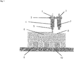
- the support structure thus provides the necessary hold for the plastic melt which is applied linearly during the layering of the melt and which forms the plastic component after solidification. The principle is in Fig. 1 illustrated.
- the plastic component After the completion or solidification of the plastic component, it is self-supporting in the areas where the overhangs or undercuts are located.
- the support structure is now superfluous or rather disturbing. It must therefore be removed, i.e. separated from the plastic component produced.
- the support structures used in the enamel layer often consist of the same material as the plastic component to be produced. In this case, the support structure has to be removed mechanically from the plastic component after it has been completed, primarily in time-consuming manual work. Even complex mechanical post-processing by means of grinding and polishing cannot always prevent residues of the support structure from sticking to the plastic component, which has a negative impact on its external appearance. The mechanical post-processing can also cause scratches in the surface of the plastic component, which also have a negative effect on its external appearance. If the support structures are removed with increased use of force, the plastic component can even be damaged beforehand.
- the present invention is therefore based on the object of providing a method which allows the production of a plastic component of complex geometry by means of melt layers, with the support structure used here should be separated from the finished plastic component after the end of the melt layering without leaving any residue or stress, without affecting its external appearance and harming the environment.
- the production method according to the invention enables residue-free and stress-free removal of the support structure after completion of the plastic component without the need for complex mechanical post-processing, for example by grinding or polishing.
- the risk of damage to the plastic component when the support structure is separated is almost entirely minimized in this way.
- This is achieved through the use of a support structure which is formed from a thermoplastic K 2 compounded with a salt. If the finished plastic component including the still adhering support structure is brought into contact with an aqueous solvent, in particular with water, after the end of the melt layering, the salt contained in the support structure and compounded together with the thermoplastic K 2 dissolves.
- the thermoplastic K 2 does not go into solution and instead remains as a porous structure. This eventually breaks down into fragments with dimensions usually in the micrometer range.
- the thermoplastic synthetic material K 2 of the support structure separates itself to a certain extent after the salt has dissolved.
- thermoplastic synthetic material K 2 of the support structure itself is not water-soluble, one can speak of a water-soluble support structure due to the water solubility of the salt contained in the support structure. If the thermoplastic K 2 is also biodegradable, the support structure can be safely disposed of with the wastewater after it has been brought into contact with the aqueous solvent, in particular with water, without causing any harmful entry of plastics into the environment.
- step (a) of the production method according to the invention a melt strand, which is formed from a thermoplastic K 1 , is deposited repeatedly to build up a plastic component with a predetermined geometry in layers.
- thermoplastic K 1 which is also referred to as a plastic filament or just a filament, occurs - after heating above the melting point of the thermoplastic K 1 - in the form of a plastic melt from the nozzle (5) to a Melt layers from a suitable 3D printing device.
- the plastic component (6) is gradually built up according to the specified geometry by linear application (8) of the plastic melt, further layers of the thermoplastic K 1 being formed on an already completed, ie solidified subcomponent of the plastic component as part of the melt layering.
- the line-like application of the plastic melt can take place on any construction platform (10) suitable for the layer of melt.
- a construction platform like her Fig. 1 represents is the support structure (9), which enables complex geometries, such as overhangs or undercuts, in the plastic component to be produced.
- the support structure can also be located on an already completed sub-component of the plastic component.
- the support structure ie exactly like the plastic component to be produced, is also built up in layers by repeatedly depositing a melt strand. This is particularly useful when several support structures are to be used at different positions, which can also only be the case in the further course of the enamel layering.
- the layered structure of the plastic component and the support structure can take place in parallel.
- a 3D printing device with at least two extruders and nozzles can suitably be used to build up the plastic component and the support structure in layers, as they do Fig. 1 shows by way of example, the 3D printing device being equipped both with filaments (1, 2) of the thermoplastic material K 1 and with filaments of the thermoplastic material K 2 compounded with the salt, as described in more detail below. Propulsion (3) and contact heating (4) of the 3D printing device are shown in Fig. 1 also illustrated.
- the present invention also includes embodiments in which more than two different plastics are used.
- two different thermoplastics K 1a and K 1b can be used, which are preferably provided from two different extruders and form the plastic component.
- These two different thermoplastics K 1a and K 1b can differ both in the type of plastic and in the color or other properties, depending on the purpose.
- the thermoplastic synthetic material K 2 from which the support structure is / is formed, can here, for example, be provided from a third extruder.
- Further combinations of plastics for example K 1a / K 1b / K 1c / K 2 or K 1 / K 2a / K 2b ) are also conceivable for the purposes of the present invention.
- the solubility of the support structure in water is based exclusively on the solubility of the salt compounded with the thermoplastic K 2 , the thermoplastic K 1 , from which the plastic component to be constructed is to be made, and the thermoplastic K 2 of the support structure can even be identical be.
- the support structure After contact with an aqueous solvent, in particular with water, the support structure remains as a porous structure made of the thermoplastic K 2 , which finally disintegrates into micrometer-sized fragments.
- the plastic component made up of the identical thermoplastic plastic is, however, not attacked due to the lack of water solubility of the thermoplastic plastic K 2 .
- thermoplastics By using identical thermoplastics, compatibility between the plastic component and the support structure is naturally guaranteed.
- support structures made of water-soluble polymers such as polyvinylpyrrolidone, which is a conventional, petroleum-based plastic that is also not biodegradable, a different thermoplastic must be used for the plastic component to be manufactured.
- thermoplastic K 1 which is used to build the plastic component, is not restricted further.
- any thermoplastic material such as is usually used in fused layers for plastic components, can also be used in the production method according to the invention.
- the thermoplastic K 1 is selected from the group consisting of polyesters, polyamides, polyurethanes, polycarbonates, polyketones and polyolefins, and optionally a thermoplastic elastomer. If desired, the thermoplastic K 1 can therefore have elastomeric properties.
- the thermoplastic K 1 can be either a homopolymer or a copolymer.
- the thermoplastic K 1 is in particular from the group consisting of polylactide (PLA), acrylonitrile-butadiene-styrene copolymer (ABS), acrylonitrile-styrene-acrylate copolymer (ASA), polymethyl methacrylate ( PMMA), polyetheretherketone (PEEK) and glycol-modified polyethylene terephthalate (PETG), selected, but not limited to.
- the thermoplastic K 1 is PLA or ABS.
- the thermoplastic K 1 should not exceed a melting temperature of about 200 ° C. so that its processability and handling in the melt layer are guaranteed.
- thermoplastic K 2 compounded with the salt, which is used to build up the support structure is not restricted further.
- any thermoplastic material as it is usually used in fused layers for support structures, can also be used in the production method according to the invention, including the materials mentioned above with regard to the thermoplastic material K 1 .
- the thermoplastic K 2 is biodegradable, as described further below, the support structure can be disposed of in the sewage without hesitation after the plastic component has been completed.
- the thermoplastic K 2 is from the group consisting of polyhydroxyalkanoates (PHA), in particular polyhydroxybutyric acid (PHB), as well as polycaprolactone (PCL), polyethylene glycol (PEG), starch, polybutylene adipate terephthalate (PBAT) and polybutylene succinate ( PBS), selected, but not limited to. All these (bio) polymers have in common that they are biodegradable. While (thermoplastic) starch, PCL and PEG are biodegradable in water, PBAT and PBS are less biodegradable in water, but are more biodegradable in soils.
- PHA polyhydroxyalkanoates
- PEG polyethylene glycol
- PBAT polybutylene adipate terephthalate
- PBS polybutylene succinate
- Polyhydroxyalkanoates which are also referred to as polyhydroxy fatty acids, can be biodegraded both in water and in soils. They are naturally occurring, water-insoluble polyesters which can be broken down aerobically or anaerobically by microorganisms such as bacteria.
- the thermoplastic material K 2 can be, for example, a Polyhydroxyalkanoate such as polyhydroxybutyric acid.
- Polyhydroxybutyric acid which is also referred to as poly (3-hydroxybutyrate), is a structurally simple and naturally occurring polyhydroxyalkanoate.
- PHB is formed by fermentation, for example based on sugar or starch, and usually consists of 1,000 to several 100,000 hydroxybutyric acid units.
- polyhydroxybutyric acid is derived from the monomer with the ( R ) configuration. It is therefore poly ( R ) - (3-hydroxybutyrate).
- the monomer with ( S ) configuration and the corresponding poly ( S ) - (3-hydroxybutyrate) only play a subordinate role, as does the racemic mixture of poly ( R ) - (3-hydroxybutyrate) and poly ( S ) - (3-hydroxybutyrate).
- Naturally occurring polyhydroxybutyric acid has a melting point of about 175 ° C, above 200 ° C decomposition occurs.
- polyhydroxybutyric acid is comparable to polypropylene, in particular with regard to its crystallinity, glass transition temperature and tensile strength.
- any stereoisomer thereof, ie whatever tacticity is understood.
- the thermoplastic K 2 forming the support structure is compounded, ie mixed, with a salt.
- the salt is added to the thermoplastic K 2 as an additive.
- all processes can be used as they are used in compounding in plastics technology.
- the compounding is typically carried out in a co-rotating twin-screw extruder.
- a counter-rotating twin screw extruder, a planetary roller extruder or a co-kneader can also be used.
- the latter is a single-screw extruder that performs both a rotary and a translational movement.
- the present invention is not particularly restricted as far as the salt for compounding with the thermoplastic K 2 is concerned.
- salts are suitably used which, in addition to a high solubility in the aqueous solvent used, in particular in water, react neither acidic nor basic with this, ie leave the pH of the aqueous solvent, in particular water, almost unchanged.
- the salts used should also only have a low hygroscopicity so that it does not occur during the enamel layering leads to excessive absorption of water, which would otherwise adversely affect the stability of the support structure.
- the salts used are neither environmentally hazardous nor otherwise dubious.
- the salt with which the thermoplastic K 2 is compounded is selected from the group consisting of sodium chloride, sodium sulfate, sodium nitrate, potassium chloride, potassium sulfate and potassium nitrate, without, however, being limited thereto.
- the chlorides, sulfates and nitrates of the light alkali metals sodium and potassium are characterized by their high solubility in water. They are also largely ecologically harmless. In principle, however, the corresponding chlorides, sulfates and nitrates of alkaline earth metals such as magnesium and calcium can also be used for compounding, as can those of other metals, provided they meet the criteria mentioned above.
- step (b) of the production method according to the invention the support structure is removed from the plastic component built up in layers in step (a) after its completion by bringing it into contact with an aqueous solvent.
- the aqueous solvent is not particularly limited and includes all solvents which have a water content of at least 50% by volume.
- the aqueous solvent can contain proportions of organic solvents such as alcohols etc. or additives such as special salts etc. Due to the easier handling and for ecological reasons, the use of an aqueous solvent which essentially, i. H. consists of at least 95% by volume of water, preferably.
- the aqueous solvent is water.
- the salt compounded together with the thermoplastic K 2 and forming the support structure dissolves as soon as it comes into contact with the aqueous solvent, in particular with water. What remains is a porous structure of the thermoplastic K 2 , which does not go into solution. Because this porous If the structure is mechanically unstable, it disintegrates into micrometer-sized fragments, which means that it can be easily separated from the finished plastic component. There is therefore no need for complex mechanical post-processing in order to remove the support structure from the finished plastic component. Rather, in the context of the production method according to the invention, the support structure separates itself to a certain extent as a result of being brought into contact with the aqueous solvent, in particular with water.
- the support structure breaks down into sufficiently small fragments while the compounded salt is being dissolved, so that almost no residues remain on the finished plastic component and no post-processing is necessary.
- a thermoplastic K 2 which is not biodegradable, is used for the support structure, the aforementioned fragments of the support structure are suitably filtered off from the aqueous solvent in order not to get into the environment.
- the mass ratio of the thermoplastic K 2 to the salt should be such that, on the one hand, a support structure can be formed from the thermoplastic K 2 compounded with the salt, for example by depositing a corresponding melt strand.
- the proportion of the thermoplastic K 2 should therefore not be too low.
- the proportion of thermoplastic K 2 should therefore not be too high.
- the mass ratio of the thermoplastic K 2 to the salt is in a range from 2: 1 to 10: 1. In this way, the aforementioned requirements are equally taken into account. Furthermore, a mass ratio in a range from 3: 1 to 8: 1 is preferred, a range from 4: 1 to 7: 1 being more preferred and a range from 5: 1 to 6: 1 being even more preferred, but without to be limited to this.
- thermoplastic K 2 is a naturally occurring polymer, as is the case with the biopolymers listed above, for example polyhydroxyalkanoates such as polyhydroxybutyric acid, microorganisms, fungi and enzymes present in the aqueous solvent, in particular in water, can destroy the fragments of the support structure, which consist of the thermoplastic K 2 , degrade.
- a simplified process can also be achieved when using a biodegradable thermoplastic K 2 Arrange for the support structure to be disposed of.
- thermoplastic K 2 Since the fragments made of the thermoplastic K 2 are only a few micrometers in size, they can easily be disposed of via the drain. A large number of microorganisms, such as bacteria, are found in wastewater, which permit degradation under aerobic or anaerobic conditions under which their growth is possible. The main breakdown products are carbon dioxide and water. In one embodiment of the production method defined above, the thermoplastic K 2 is correspondingly biodegradable. In this case, there is no need to filter off the aforementioned fragments of the support structure from the aqueous solvent.
- thermoplastic K 2 which is not itself water-soluble, can be selected for this purpose from the group consisting of polyhydroxyalkanoates, in particular polyhydroxybutyric acid, as well as polycaprolactone, polyethylene glycol, starch, polybutylene adipate terephthalate and polybutylene succinate, but without each other to restrict to this.
- the present invention relates to a filament for use as a support structure, for example in the production method according to the invention, the filament consisting of the thermoplastic K 2 , which is compounded with the salt.
- the filament according to the invention with respect to the thermoplastic K 2 and the salt compounded therewith, all statements as described above in connection with the production method according to the invention apply in the same way.
- the filament according to the invention can have a diameter in the range from 1 mm to 4 mm, for example 1.5 mm to 3.5 mm. Commercially available diameters are e.g. B. 1.75 mm or 2.85 mm.
- the present invention allows a simple, residue-free and stress-free separation of the support structure from a plastic component of complex geometry, which is produced by melt layers. Since there is no need for mechanical post-processing, there is no impairment of the external appearance of the plastic component produced. In particular, its surface quality is not negatively affected. This is achieved through the use of a support structure which is formed from a thermoplastic K 2 compounded with a salt.
- the present invention also allows simple disposal of the support structure, provided that the thermoplastic synthetic material K 2 is biodegradable.
- the aqueous solvent brought into contact with the support structure, in particular water can for example simply be added to the drain.
- Microorganisms, fungi or enzymes contained in the wastewater finally degrade the thermoplastic K 2 of the support structure, which has broken down into fragments as a result of the contact with the aqueous solvent, in particular water. Since neither acids nor bases have to be used in the production process according to the invention, microorganisms such as bacteria, which are sensitive to the pH value of the water, are not impaired in their livelihood by the disposal of the support structure with the waste water.
- thermoplastic K 2 Due to their small size in the micrometer range, the fragments of the thermoplastic K 2 emerging from the support structure have a high specific surface area, which further accelerates the biological degradation process. Thus, indirectly, no residues of the thermoplastic material K 2 originating from the support structure remain in the environment. In contrast, in the case of a support structure made of water-soluble but not biodegradable thermoplastics, only a physical breakdown of the polymer chains occurs, ie the polymer chains remain intact. If the environmental conditions change, for example Temperature, mineral content or pH value, the thermoplastic can precipitate again and then remain in the environment as microplastics, for example in the form of individual polymer chains. This finally finds its way into the food chain via soil or water. The manufacturing method according to the invention and the filament according to the invention do not have any of these problems, in particular if the thermoplastic K 2 used for the support structure is biodegradable.
- Fig. 1 shows schematically the depositing of a melt strand in the context of the melt layering, including the supporting structure used. This is used to realize plastic components of complex geometry, which have overhangs or undercuts, for example.
Landscapes
- Chemical & Material Sciences (AREA)
- Engineering & Computer Science (AREA)
- Materials Engineering (AREA)
- Physics & Mathematics (AREA)
- Manufacturing & Machinery (AREA)
- Mechanical Engineering (AREA)
- Optics & Photonics (AREA)
- Laminated Bodies (AREA)
Abstract
Die vorliegende Erfindung betrifft ein Verfahren zur Herstellung eines Kunststoffbauteiles durch Schmelzschichten, wobei das herzustellende Kunststoffbauteil eine komplexe Geometrie aufweisen soll, welche den Einsatz einer Stützstruktur während des schichtweisen Aufbaus des Kunststoffbauteiles erfordert. Das erfindungsgemäße Herstellungsverfahren ist dadurch gekennzeichnet, dass die Stützstruktur aus einem thermoplastischen Kunststoff K2, welcher mit einem Salz compoundiert ist, gebildet ist, wobei der thermoplastische Kunststoff K2 biologisch abbaubar sein kann. Ferner betrifft die vorliegende Erfindung ein Filament zur Verwendung als Stützstruktur in dem erfindungsgemäßen Herstellungsverfahren.
Description
- Die vorliegende Erfindung betrifft ein Verfahren zur Herstellung eines Kunststoffbauteiles durch Schmelzschichten, wobei das herzustellende Kunststoffbauteil eine komplexe Geometrie aufweisen soll, welche den Einsatz einer Stützstruktur erfordert. Ferner betrifft die vorliegende Erfindung ein Filament zur Verwendung als Stützstruktur in dem erfindungsgemäßen Herstellungsverfahren.
- Im Stand der Technik sind verschiedene additive Fertigungsverfahren bekannt, um Kunststoffbauteile unter Anwendung eines 3D-Drucks in Kleinserien oder als Prototyp herzustellen, wie etwa das selektive Lasersintern (engl. selective laser sintering, SLS) oder das Schmelzschichten (engl. fused deposition modeling, FDM). Das auch als Strangablegeverfahren bezeichnete Schmelzschichten ist ein Fertigungsverfahren aus dem Bereich Rapid Prototyping, mit dem ein Bauteil schichtweise aus einem schmelzfähigen Ausgangsstoff, beispielsweise einem schmelzfähigen Kunststoff, aufgebaut wird.
- Um in einem derartigen mittels Schmelzschichten herzustellenden Kunststoffbauteil komplexe Geometrien, wie etwa Überhänge bzw. Hinterschneidungen, zu ermöglichen, bedarf es des Einsatzes einer Stützstruktur. Stützstrukturen, welche synonym auch als Stützkonstruktionen bezeichnet werden, kommen überall dort zum Einsatz, wo das herzustellende Kunststoffbauteil freistehend bzw. freihängend sein soll, d. h. an all jenen Stellen, die ansonsten frei im Raum, also ohne Stützung durch eine bereits fertiggestellte Teilkomponente des Kunststoffbauteiles, entstehen würden. Die Stützstruktur vermittelt somit den notwendigen Halt der während des Schmelzschichtens linienartig aufgetragenen Kunststoffschmelze, welche nach Erstarrung das Kunststoffbauteil bildet. Das Prinzip ist in
Fig. 1 veranschaulicht. - Nach der Fertigstellung bzw. dem Erstarren des Kunststoffbauteiles ist dieses in den Bereichen, wo sich die Überhänge bzw. Hinterschneidungen befinden, selbsttragend.
- Die Stützstruktur ist nunmehr überflüssig bzw. vielmehr störend. Sie muss daher entfernt, also von dem hergestellten Kunststoffbauteil abgetrennt werden. Häufig bestehen die im Schmelzschichten eingesetzten Stützstrukturen aus dem gleichen Werkstoff wie das herzustellende Kunststoffbauteil. In diesem Fall muss die Stützstruktur nach der Fertigstellung des Kunststoffbauteiles mechanisch von diesem entfernt werden, vorwiegend in zeitintensiver Handarbeit. Selbst eine aufwendige mechanische Nachbearbeitung mittels Schleifen und Polieren kann hierbei nicht immer verhindern, dass Rückstände der Stützstruktur am Kunststoffbauteil haften bleiben, was dessen äußeres Erscheinungsbild negativ beeinflusst. Ebenso können durch die mechanische Nachbearbeitung Kratzer in der Oberfläche des Kunststoffbauteiles entstehen, welche sich ebenfalls negativ auf dessen äußeres Erscheinungsbild auswirken. Werden die Stützstrukturen unter erhöhtem Krafteinsatz entfernt, kann es sogar zu einer Vorschädigung des Kunststoffbauteiles kommen.
- Zwar wurde in diesem Zusammenhang durch die Kombination unterschiedlicher Werkstoffe für das Kunststoffbauteil und für die Stützstruktur, welche weniger stark aneinander haften, eine Verbesserung erzielt. Da es jedoch beim Stützen des Kunststoffbauteiles notwendigerweise zu einer Kraftübertragung auf die Stützstruktur kommt, kann zwar die Haftung verringert, jedoch nie vollständig unterbunden werden. Somit lassen sich auch bei Verwendung unterschiedlicher Werkstoffe die vorstehend beschriebenen Probleme, wie sie bislang beim Entfernen der Stützstruktur auftreten, nicht vollständig vermeiden.
- Im Stand der Technik sind auch Stützstrukturen aus wasserlöslichen Polymeren, wie etwa Polyvinylpyrrolidon, bekannt, die nach der Fertigstellung des Kunststoffbauteiles ausgewaschen werden können. Die in Wasser gelösten Polymerketten der Stützstruktur können jedoch nicht über eine übliche Kläranlage aus dem Abwasser entfernt werden, womit sie letztlich in die Umwelt gelangen. Die Folgen dieser Art der Umweltverschmutzung auf Mensch und Natur sind noch nicht erforscht.
- Der vorliegenden Erfindung liegt somit die Aufgabe zugrunde, ein Verfahren bereitzustellen, welches die Herstellung eines Kunststoffbauteiles komplexer Geometrie durch Schmelzschichten erlaubt, wobei sich die hierbei zum Einsatz kommende Stützstruktur nach Beendigung des Schmelzschichtens rückstands- und belastungsfrei von dem fertiggestellten Kunststoffbauteil abtrennen lassen soll, ohne dabei dessen äußeres Erscheinungsbild zu beeinträchtigen und die Umwelt zu schädigen.
- Diese Aufgabe wird durch die in den Ansprüchen gekennzeichneten Ausführungsformen der vorliegenden Erfindung gelöst.
- Insbesondere wird erfindungsgemäß ein Verfahren zur Herstellung eines Kunststoffbauteiles durch Schmelzschichten bereitgestellt, welches die folgenden Schritte (a) und (b) umfasst:
- (a) wiederholtes Ablegen eines Schmelzstranges, welcher aus einem thermoplastischen Kunststoff K1 gebildet ist, zum schichtweisen Aufbau eines Kunststoffbauteiles mit vorgegebener Geometrie, wobei während des schichtweisen Aufbaus des Kunststoffbauteiles eine Stützstruktur, welche Überhänge bzw. Hinterschneidungen im Kunststoffbauteil ermöglicht, verwendet wird, und
- (b) Entfernen der Stützstruktur von dem in Schritt (a) schichtweise aufgebauten Kunststoffbauteil nach dessen Fertigstellung durch Inkontaktbringen mit einem wässrigen Lösungsmittel,
- Das erfindungsgemäße Herstellungsverfahren ermöglicht ein rückstands- und belastungsfreies Entfernen der Stützstruktur nach Fertigstellung des Kunststoffbauteiles, ohne dass es einer aufwendigen mechanischen Nachbearbeitung, etwa durch Schleifen oder Polieren, bedarf. Die Gefahr einer Beschädigung des Kunststoffbauteiles beim Abtrennen der Stützstruktur wird auf diese Weise nahezu gänzlich minimiert. Erreicht wird dies durch den Einsatz einer Stützstruktur, welche aus einem thermoplastischen Kunststoff K2, der mit einem Salz compoundiert ist, gebildet ist. Wird nach Beendigung des Schmelzschichtens das fertiggestellte Kunststoffbauteil einschließlich der noch anhaftenden Stützstruktur mit einem wässrigen Lösungsmittel, insbesondere mit Wasser, in Kontakt gebracht, löst sich das in der Stützstruktur enthaltene und zusammen mit dem thermoplastischen Kunststoff K2 compoundierte Salz auf. Der thermoplastische Kunststoff K2 geht hingegen nicht in Lösung und bleibt stattdessen als poröses Gebilde zurück. Dieses zerfällt schließlich in Bruchstücke mit Abmessungen üblicherweise im Mikrometerbereich. Der thermoplastische Kunststoff K2 der Stützstruktur trennt sich nach dem Auflösen des Salzes somit gewissermaßen von allein ab.
- Auch wenn der thermoplastische Kunststoff K2 der Stützstruktur selbst nicht wasserlöslich ist, kann aufgrund der Wasserlöslichkeit des in der Stützstruktur enthaltenen Salzes von einer wasserlöslichen Stützstruktur gesprochen werden. Ist der thermoplastische Kunststoff K2 zudem biologisch abbaubar, kann die Stützstruktur nach dem Inkontaktbringen mit dem wässrigen Lösungsmittel, insbesondere mit Wasser, bedenkenlos mit dem Abwasser entsorgt werden, ohne hierbei einen schädlichen Eintrag von Kunststoffen in die Umwelt zu verursachen.
- Im Folgenden wird das erfindungsgemäße Verfahren zur Herstellung eines Kunststoffbauteiles durch Schmelzschichten mit den Schritten (a) und (b) näher beschrieben.
- In Schritt (a) des erfindungsgemäßen Herstellungsverfahrens wird ein Schmelzstrang, welcher aus einem thermoplastischen Kunststoff K1 gebildet ist, wiederholt zum schichtweisen Aufbau eines Kunststoffbauteiles mit vorgegebener Geometrie abgelegt.
- Das wiederholte Ablegen des Schmelzstranges kann, wie in
Fig. 1 dargestellt, mit Hilfe eines (Mini-)Extruders (7) erfolgen. Ein aus dem thermoplastischen Kunststoff K1 bestehender Kunststoffdraht (1), welcher auch als Kunststofffilament oder nur als Filament bezeichnet wird, tritt - nach Erwärmen über den Schmelzpunkt des thermoplastischen Kunststoffes K1 hinaus - in Form einer Kunststoffschmelze aus der Düse (5) einer zum Schmelzschichten geeigneten 3D-Druckvorrichtung aus. Durch linienartige Auftragung (8) der Kunststoffschmelze wird nach und nach das Kunststoffbauteil (6) entsprechend der vorgegebenen Geometrie aufgebaut, wobei im Rahmen des Schmelzschichtens auf einer bereits fertiggestellten, d. h. erstarrten Teilkomponente des Kunststoffbauteiles weitere Schichten des thermoplastischen Kunststoffes K1 entstehen. - Das linienartige Auftragen der Kunststoffschmelze kann auf einer beliebigen für das Schmelzschichten geeigneten Bauplattform (10) erfolgen. Beispielsweise auf einer solchen Bauplattform, wie sie
Fig. 1 darstellt, befindet sich die Stützstruktur (9), welche komplexe Geometrien, wie etwa Überhänge bzw. Hinterschneidungen, im herzustellenden Kunststoffbauteil ermöglicht. In gleicher Weise kann sich die Stützstruktur jedoch auch auf einer bereits fertiggestellten Teilkomponente des Kunststoffbauteiles befinden. - In einer Ausführungsform des vorstehend definierten Herstellungsverfahrens wird ebenfalls die Stützstruktur, d. h. genau wie das herzustellende Kunststoffbauteil, durch wiederholtes Ablegen eines Schmelzstranges schichtweise aufgebaut. Dies ist insbesondere dann zweckmäßig, wenn mehrere Stützstrukturen an unterschiedlichen Positionen zum Einsatz kommen sollen, was auch erst im weiteren Verlauf des Schmelzschichtens der Fall sein kann. Der schichtweise Aufbau des Kunststoffbauteiles und der Stützstruktur kann hierbei parallel erfolgen. Geeigneterweise kann zum schichtweisen Aufbau des Kunststoffbauteiles und der Stützstruktur eine 3D-Druckvorrichtung mit mindestens zwei Extrudern und Düsen verwendet werden, wie sie
Fig. 1 exemplarisch darstellt, wobei die 3D-Druckvorrichtung sowohl mit Filamenten (1, 2) des thermoplastischen Kunststoffes K1 als auch mit Filamenten des mit dem Salz compoundierten thermoplastischen Kunststoffes K2 ausgestattet ist, wie weiter unten näher beschrieben. Vortrieb (3) sowie Kontaktheizung (4) der 3D-Druckvorrichtung sind inFig. 1 ebenfalls veranschaulicht. - Darüber hinaus umfasst die vorliegende Erfindung auch Ausführungsformen, in welchen mehr als zwei verschiedene Kunststoffe zum Einsatz kommen. Beispielweise können zwei verschiedene thermoplastische Kunststoffe K1a und K1b verwendet werden, welche vorzugsweise aus zwei verschiedenen Extrudern bereitgestellt werden und das Kunststoffbauteil bilden. Diese zwei verschiedenen thermoplastischen Kunststoffe K1a und K1b können sich je nach Zweck sowohl in der Art des Kunststoffes als auch in der Farbe oder anderen Eigenschaften unterscheiden. Der thermoplastische Kunststoff K2, aus welchem die Stützstruktur gebildet ist/wird, kann hier beispielsweise aus einem dritten Extruder bereitgestellt werden. Weitere Kombinationen von Kunststoffen (etwa K1a/K1b/K1c/K2 oder K1/K2a/K2b) sind ebenfalls im Sinne der vorliegenden Erfindung denkbar.
- Da gemäß der vorliegenden Erfindung die Wasserlöslichkeit der Stützstruktur ausschließlich auf der Löslichkeit des mit dem thermoplastischen Kunststoff K2 compoundierten Salzes beruht, können der thermoplastische Kunststoff K1, aus dem das aufzubauende Kunststoffbauteil gefertigt werden soll, und der thermoplastische Kunststoff K2 der Stützstruktur sogar identisch sein. So bleibt nach Kontakt mit einem wässrigen Lösungsmittel, insbesondere mit Wasser, die Stützstruktur als ein poröses Gebilde aus dem thermoplastischen Kunststoff K2 zurück, welches schließlich in mikrometergroße Bruchstücke zerfällt. Das aus dem identischen thermoplastischen Kunststoff aufgebaute Kunststoffbauteil wird aufgrund der fehlenden Wasserlöslichkeit des thermoplastischen Kunststoffes K2 hingegen nicht angegriffen.
- Durch die Verwendung identischer thermoplastischer Kunststoffe ist eine Kompatibilität zwischen dem Kunststoffbauteil und der Stützstruktur naturgemäß gewährleistet. Bei Stützstrukturen aus wasserlöslichen Polymeren, wie etwa Polyvinylpyrrolidon, bei dem es sich um einen konventionellen, erdölbasierten Kunststoff handelt, welcher zudem nicht biologisch abbaubar ist, muss für das herzustellende Kunststoffbauteil hingegen zwangsläufig ein anderer thermoplastischer Kunststoff verwendet werden.
- Gemäß der vorliegenden Erfindung ist der thermoplastische Kunststoff K1, welcher dem Aufbau des Kunststoffbauteiles dient, nicht weiter eingeschränkt. So kann grundsätzlich jeder thermoplastische Kunststoff, wie er üblicherweise im Schmelzschichten für Kunststoffbauteile eingesetzt wird, auch im erfindungsgemäßen Herstellungsverfahren verwendet werden.
- In einer Ausführungsform des vorstehend definierten Herstellungsverfahrens ist der thermoplastische Kunststoff K1 aus der Gruppe, bestehend aus Polyestern, Polyamiden, Polyurethanen, Polycarbonaten, Polyketonen und Polyolefinen, ausgewählt und gegebenenfalls ein thermoplastisches Elastomer. Falls gewünscht, kann der thermoplastische Kunststoff K1 also elastomere Eigenschaften aufweisen. Bei dem thermoplastischen Kunststoff K1 kann es sich sowohl um ein Homopolymer als auch um ein Copolymer handeln. In einer weiteren Ausführungsform des vorstehend definierten Herstellungsverfahrens ist der thermoplastische Kunststoff K1 insbesondere aus der Gruppe, bestehend aus Polylactid (PLA), Acrylnitril-Butadien-Styrol-Copolymer(ABS), Acrylnitril-Styrol-Acrylat-Copolymer (ASA), Polymethylmethacrylat (PMMA), Polyetheretherketon (PEEK) und Glykol-modifiziertem Polyethylenterephthalat (PETG), ausgewählt, ohne jedoch hierauf beschränkt zu sein. Gemäß einer bevorzugten Ausführungsform der vorliegenden Erfindung ist der thermoplastische Kunststoff K1 PLA oder ABS.
- Typischerweise sollte der thermoplastische Kunststoff K1 eine Schmelztemperatur von etwa 200 °C nicht überschreiten, damit seine Verarbeitbarkeit und Handhabung im Schmelzschichten gewährleistet bleiben.
- Gemäß der vorliegenden Erfindung ist der mit dem Salz compoundierte thermoplastische Kunststoff K2, welcher dem Aufbau der Stützstruktur dient, nicht weiter eingeschränkt. So kann grundsätzlich jeder thermoplastische Kunststoff, wie er üblicherweise im Schmelzschichten für Stützstrukturen eingesetzt wird, auch im erfindungsgemäßen Herstellungsverfahren verwendet werden, einschließlich der bezüglich des thermoplastischen Kunststoffes K1 vorstehend genannten Werkstoffe. Ist der thermoplastische Kunststoff K2 biologisch abbaubar, wie weiter unten beschrieben, ist eine Entsorgung der Stützstruktur nach der Fertigstellung des Kunststoffbauteiles über das Abwasser bedenkenlos möglich.
- In einer Ausführungsform des vorstehend definierten Herstellungsverfahrens ist der thermoplastische Kunststoff K2 aus der Gruppe, bestehend aus Polyhydroxyalkanoaten (PHA), insbesondere Polyhydroxybuttersäure (PHB), sowie Polycaprolacton (PCL), Polyethylenglykol (PEG), Stärke, Polybutylenadipatterephthalat (PBAT) und Polybutylensuccinat (PBS), ausgewählt, ohne jedoch hierauf beschränkt zu sein. All diesen (Bio-)Polymeren ist gemein, dass sie biologisch abbaubar sind. Während (thermoplastische) Stärke, PCL und PEG in Gewässern biologisch abbaubar sind, sind PBAT und PBS weniger in Gewässern, dafür aber in Böden biologisch abbaubar.
- Polyhydroxyalkanoate, welche auch als Polyhydroxyfettsäuren bezeichnet werden, lassen sich sowohl in Gewässern als auch in Böden biologisch abbauen. Bei ihnen handelt es sich um natürlich vorkommende, wasserunlösliche Polyester, welche von Mikroorganismen, beispielsweise Bakterien, aerob oder anaerob abgebaut werden können. Bei dem thermoplastischen Kunststoff K2 kann es sich beispielsweise um ein Polyhydroxyalkanoat, wie etwa Polyhydroxybuttersäure, handeln. Polyhydroxybuttersäure, welche auch als Poly(3-hydroxybutyrat) bezeichnet wird, ist ein strukturell einfaches und in der Natur häufig vorkommendes Polyhydroxyalkanoat. PHB wird durch Fermentation gebildet, beispielsweise auf Basis von Zucker oder Stärke, und besteht üblicherweise aus 1.000 bis mehreren 100.000 Hydroxybuttersäureeinheiten. Zumeist leitet sich die natürlich vorkommende Polyhydroxybuttersäure von dem Monomer mit (R)-Konfiguration ab. Es handelt sich demnach um Poly-(R)-(3-hydroxybutyrat). Das Monomer mit (S)-Konfiguration und das entsprechende Poly-(S)-(3-hydroxybutyrat) spielen demgegenüber lediglich eine untergeordnete Rolle, ebenso wie die racemische Mischung aus Poly-(R)-(3-hydroxybutyrat) und Poly-(S)-(3-hydroxybutyrat). Natürlich vorkommende Polyhydroxybuttersäure weist einen Schmelzpunkt von etwa 175 °C auf, oberhalb von 200 °C tritt Zersetzung ein. In einem Teil ihrer Eigenschaften ist Polyhydroxybuttersäure mit Polypropylen vergleichbar, insbesondere hinsichtlich ihrer Kristallinität, Glasübergangstemperatur und Zugfestigkeit. Vorliegend wird, wenn auf Polyhydroxybuttersäure Bezug genommen wird, jedwedes Stereoisomer hiervon, d. h. gleich welcher Taktizität, verstanden.
- Gemäß der vorliegenden Erfindung ist der die Stützstruktur bildende thermoplastische Kunststoff K2 mit einem Salz compoundiert, d. h. gemischt. Das Salz wird als Zuschlagstoff dem thermoplastischen Kunststoff K2 beigemischt. Zu diesem Zweck können alle Verfahren herangezogen werden, wie sie beim Compoundieren in der Kunststofftechnik eingesetzt werden. Typischerweise erfolgt die Compoundierung in einem gleichläufigen Doppelschneckenextruder. Es kann jedoch auch ein gegenläufiger Doppelschneckenextruder, ein Planetwalzenextruder oder ein Ko-Kneter verwendet werden. Bei Letzterem handelt es sich um einen Einschneckenextruder, der sowohl eine rotatorische als auch eine translatorische Bewegung ausführt.
- Grundsätzlich ist die vorliegende Erfindung, was das Salz zur Compoundierung mit dem thermoplastischen Kunststoff K2 anbelangt, nicht besonders eingeschränkt. Geeigneterweise werden hierzu Salze verwendet, welche neben einer hohen Löslichkeit in dem verwendeten wässrigen Lösungsmittel, insbesondere in Wasser, mit diesem weder sauer noch basisch reagieren, d. h. den pH-Wert des wässrigen Lösungsmittels, insbesondere von Wasser, nahezu unverändert lassen. Auch sollten die eingesetzten Salze lediglich eine geringe Hygroskopizität aufweisen, damit es nicht bereits während des Schmelzschichtens zu einer übermäßigen Aufnahme von Wasser kommt, was ansonsten die Stabilität der Stützstruktur nachteilig beeinflussen würde. Idealerweise sind die zum Einsatz kommenden Salze weder umweltgefährlich noch anderweitig bedenklich.
- In einer Ausführungsform des vorstehend definierten Herstellungsverfahrens ist das Salz, mit welchem der thermoplastische Kunststoff K2 compoundiert ist, aus der Gruppe, bestehend aus Natriumchlorid, Natriumsulfat, Natriumnitrat, Kaliumchlorid, Kaliumsulfat und Kaliumnitrat, ausgewählt, ohne jedoch hierauf beschränkt zu sein. Die Chloride, Sulfate und Nitrate der leichten Alkalimetalle Natrium und Kalium zeichnen sich durch ihre hohe Wasserlöslichkeit aus. Auch sind sie ökologisch weitestgehend unbedenklich. Grundsätzlich können jedoch auch die entsprechenden Chloride, Sulfate und Nitrate von Erdalkalimetallen wie Magnesium und Calcium zur Compoundierung verwendet werden, wie auch diejenigen anderer Metalle, sofern sie die vorstehend genannten Kriterien erfüllen.
- In Schritt (b) des erfindungsgemäßen Herstellungsverfahrens wird die Stützstruktur von dem in Schritt (a) schichtweise aufgebauten Kunststoffbauteil nach dessen Fertigstellung durch Inkontaktbringen mit einem wässrigen Lösungsmittel entfernt.
- Gemäß der vorliegenden Erfindung ist das wässrige Lösungsmittel nicht besonders eingeschränkt und schließt sämtliche Lösungsmittel ein, die einen Wasseranteil von mindestens 50 Vol.-% aufweisen. Je nach Anwendung kann das wässrige Lösungsmittel Anteile von organischen Lösungsmitteln, wie Alkoholen usw. oder Additive, wie spezielle Salze usw. aufweisen. Aufgrund der einfacheren Handhabbarkeit und aus ökologischen Gründen ist die Verwendung eines wässrigen Lösungsmittels, welches im Wesentlichen, d. h. aus mindestens 95 Vol.-% Wasser besteht, bevorzugt. Gemäß einer spezifischen Ausführungsform der vorliegenden Erfindung ist das wässrige Lösungsmittel Wasser.
- Das zusammen mit dem thermoplastischen Kunststoff K2 compoundierte und die Stützstruktur bildende Salz löst sich, sobald es mit dem wässrigen Lösungsmittel, insbesondere mit Wasser, in Kontakt kommt, auf. Zurück bleibt ein poröses Gebilde des thermoplastischen Kunststoffes K2, welcher nicht in Lösung geht. Da dieses poröse Gebilde mechanisch instabil ist, zerfällt es in mikrometergroße Bruchstücke, wodurch es sich von dem fertiggestellten Kunststoffbauteil leicht abtrennen lässt. Es bedarf somit keiner aufwendigen mechanischen Nachbearbeitung, um die Stützstruktur von dem fertiggestellten Kunststoffbauteil zu entfernen. Vielmehr trennt sich im Rahmen des erfindungsgemäßen Herstellungsverfahrens die Stützstruktur in Folge des Inkontaktbringens mit dem wässrigen Lösungsmittel, insbesondere mit Wasser, gewissermaßen von allein ab. Idealerweise zerfällt die Stützstruktur bereits während des Auflösens des compoundierten Salzes in ausreichend kleine Bruchstücke, so dass nahezu keinerlei Rückstände am fertiggestellten Kunststoffbauteil verbleiben und keine Nachbearbeitung notwendig ist. Wird für die Stützstruktur ein thermoplastischer Kunststoff K2 verwendet, welcher nicht biologisch abbaubar ist, werden die vorstehend erwähnten Bruchstücke der Stützstruktur geeigneterweise aus dem wässrigen Lösungsmittel abfiltriert, um nicht in die Umwelt zu gelangen.
- Das Massenverhältnis des thermoplastischen Kunststoffes K2 zu dem Salz sollte dabei dergestalt sein, dass zum einen aus dem mit dem Salz compoundierten thermoplastischen Kunststoff K2 eine Stützstruktur gebildet werden kann, beispielsweise durch Ablegen eines entsprechenden Schmelzstranges. Der Anteil des thermoplastischen Kunststoffes K2 sollte also nicht zu niedrig gewählt sein. Zum anderen muss aber auch sichergestellt sein, dass das nach Inkontaktbringen mit dem wässrigen Lösungsmittel, insbesondere mit Wasser, zurückbleibende poröse Gebilde aus dem thermoplastischen Kunststoff K2 ohne äußeres Zutun in einzelne Bruchstücke zerfällt. Der Anteil des thermoplastischen Kunststoffes K2 sollte demnach auch nicht zu hoch gewählt sein.
- In einer Ausführungsform des vorstehend definierten Herstellungsverfahrens liegt das Massenverhältnis des thermoplastischen Kunststoffes K2 zu dem Salz in einem Bereich von 2:1 bis 10:1. Hierdurch wird den vorstehend genannten Erfordernissen gleichermaßen Rechnung getragen. Weiterhin ist hierbei ein Massenverhältnis in einem Bereich von 3:1 bis 8:1 bevorzugt, wobei ein Bereich von 4:1 bis 7:1 mehr bevorzugt ist und ein Bereich von 5:1 bis 6:1 noch mehr bevorzugt ist, ohne jedoch hierauf beschränkt zu sein.
- Ist der thermoplastische Kunststoff K2 ein natürlich vorkommendes Polymer, wie dies bei den vorstehend aufgezeigten Biopolymeren, beispielsweise Polyhydroxyalkanoaten, wie etwa Polyhydroxybuttersäure, der Fall ist, können im wässrigen Lösungsmittel, insbesondere im Wasser, vorhandene Mikroorganismen, Pilze und Enzyme die Bruchstücke der Stützstruktur, welche aus dem thermoplastischen Kunststoff K2 bestehen, abbauen. Neben der vereinfachten Abtrennbarkeit der Stützstruktur, welche auf die Compoundierung mit dem Salz und dessen Herauslösen aus der Stützstruktur bei Inkontaktbringen mit dem wässrigen Lösungsmittel, insbesondere mit Wasser, zurückgeführt werden kann, lässt sich bei Verwendung eines biologisch abbaubaren thermoplastischen Kunststoffes K2 ferner also eine vereinfachte Entsorgung der Stützstruktur herbeiführen. Da die aus dem thermoplastischen Kunststoff K2 bestehenden Bruchstücke nur wenige Mikrometer groß sind, können diese auf einfache Weise über den Abfluss entsorgt werden. Gerade im Abwasser befindet sich eine Vielzahl von Mikroorganismen, wie etwa Bakterien, die einen Abbau unter aeroben oder anaeroben Bedingungen, unter denen ihr Wachstum möglich ist, erlauben. Abbauprodukte sind hierbei im Wesentlichen Kohlenstoffdioxid und Wasser. In einer Ausführungsform des vorstehend definierten Herstellungsverfahrens ist der thermoplastische Kunststoff K2 entsprechend biologisch abbaubar. Eines Abfiltrierens der vorstehend erwähnten Bruchstücke der Stützstruktur aus dem wässrigen Lösungsmittel bedarf es in diesem Fall also nicht.
- In Einklang mit den vorstehenden Ausführungen kann der thermoplastische Kunststoff K2, welcher selbst nicht wasserlöslich ist, zu diesem Zweck aus der Gruppe, bestehend aus Polyhydroxyalkanoaten, insbesondere Polyhydroxybuttersäure, sowie Polycaprolacton, Polyethylenglykol, Stärke, Polybutylenadipatterephthalat und Polybutylensuccinat, ausgewählt sein, ohne sich jedoch hierauf zu beschränken.
- In einem weiteren Aspekt betrifft die vorliegende Erfindung ein Filament zur Verwendung als Stützstruktur beispielsweise in dem erfindungsgemäßen Herstellungsverfahren, wobei das Filament aus dem thermoplastischen Kunststoff K2, welcher mit dem Salz compoundiert ist, besteht. Für das erfindungsgemäße Filament gelten in Bezug auf den thermoplastischen Kunststoff K2 und das damit compoundierte Salz alle Ausführungen, wie weiter oben im Zusammenhang mit dem erfindungsgemäßen Herstellungsverfahren beschrieben, auf gleiche Weise. Ohne hierauf beschränkt zu sein, kann das erfindungsgemäße Filament einen Durchmesser im Bereich von 1 mm bis 4 mm, beispielsweise 1,5 mm bis 3,5 mm, aufweisen. Handelsübliche Durchmesser sind z. B. 1,75 mm oder 2,85 mm.
- Die vorliegende Erfindung erlaubt ein einfaches, rückstands- und belastungsfreies Abtrennen der Stützstruktur von einem Kunststoffbauteil komplexer Geometrie, welches durch Schmelzschichten hergestellt wird. Da es keiner mechanischen Nachbearbeitung bedarf, kommt es zu keiner Beeinträchtigung des äußeren Erscheinungsbildes des hergestellten Kunststoffbauteiles. Insbesondere wird dessen Oberflächenqualität nicht negativ beeinflusst. Erreicht wird dies durch den Einsatz einer Stützstruktur, welche aus einem mit einem Salz compoundierten thermoplastischen Kunststoff K2 gebildet ist.
- Darüber hinaus erlaubt die vorliegende Erfindung auch ein einfaches Entsorgen der Stützstruktur, sofern der thermoplastische Kunststoff K2 biologisch abbaubar ist. In diesem Fall kann das mit der Stützstruktur in Kontakt gebrachte wässrige Lösungsmittel, insbesondere Wasser, beispielsweise einfach in den Abfluss gegeben werden. Im Abwasser enthaltene Mikroorganismen, Pilze oder Enzyme bauen den in Folge des Inkontaktbringens mit dem wässrigen Lösungsmittel, insbesondere Wasser, in Bruchstücke zerfallenen thermoplastischen Kunststoff K2 der Stützstruktur schließlich ab. Da im Rahmen des erfindungsgemäßen Herstellungsverfahrens weder Säuren noch Basen eingesetzt werden müssen, werden Mikroorganismen, wie etwa Bakterien, welche empfindlich auf den pH-Wert des Wassers reagieren, durch die Entsorgung der Stützstruktur mit dem Abwasser auch nicht in ihrer Lebensgrundlage gestört.
- Aufgrund ihrer geringen Größe im Mikrometerbereich weisen die aus der Stützstruktur hervorgehenden Bruchstücke des thermoplastischen Kunststoffes K2 eine hohe spezifische Oberfläche auf, was den biologischen Abbauprozess weiter beschleunigt. Mittelbar verbleiben somit keine Rückstände des aus der Stützstruktur stammenden thermoplastischen Kunststoffes K2 in der Umwelt. Dahingegen kommt es im Falle einer Stützstruktur aus wasserlöslichen, aber nicht biologisch abbaubaren thermoplastischen Kunststoffen lediglich zu einer physikalischen Auflösung der Polymerketten, d. h. die Polymerketten bleiben intakt. Ändern sich die Umgebungsbedingungen, beispielsweise Temperatur, Mineralstoffgehalt oder pH-Wert, kann der thermoplastische Kunststoff wieder ausfallen und verbleibt sodann als Mikroplastik, etwa in Form einzelner Polymerketten, in der Umwelt. Über Böden oder Gewässer gelangt dieser schließlich in die Nahrungskette. All jene Probleme weisen das erfindungsgemäße Herstellungsverfahren sowie das erfindungsgemäße Filament nicht auf, insbesondere wenn der für die Stützstruktur verwendete thermoplastische Kunststoff K2 biologisch abbaubar ist.
-
Fig. 1 zeigt schematisch das Ablegen eines Schmelzstranges im Rahmen des Schmelzschichtens, einschließlich der dabei zum Einsatz kommenden Stützstruktur. Diese dient der Realisierung von Kunststoffbauteilen komplexer Geometrie, welche etwa Überhänge bzw. Hinterschneidungen aufweisen. -
- 1
- Kunststoffdraht/-filament (enthaltend den thermoplastischen Kunststoff K1) für das Kunststoffbauteil
- 2
- Kunststoffdraht/-filament (enthaltend den thermoplastischen Kunststoff K2) für die Stützstruktur
- 3
- Vortrieb
- 4
- Kontaktheizung
- 5
- Düse
- 6
- Kunststoffbauteil
- 7
- Extruder
- 8
- linienartige Auftragung
- 9
- Stützstruktur
- 10
- Bauplattform
Claims (12)
- Verfahren zur Herstellung eines Kunststoffbauteiles durch Schmelzschichten, umfassend die folgenden Schritte (a) und (b):(a) wiederholtes Ablegen eines Schmelzstranges, welcher aus einem thermoplastischen Kunststoff K1 gebildet ist, zum schichtweisen Aufbau eines Kunststoffbauteiles mit vorgegebener Geometrie, wobei während des schichtweisen Aufbaus des Kunststoffbauteiles eine Stützstruktur, welche Überhänge bzw. Hinterschneidungen im Kunststoffbauteil ermöglicht, verwendet wird, und(b) Entfernen der Stützstruktur von dem in Schritt (a) schichtweise aufgebauten Kunststoffbauteil nach dessen Fertigstellung durch Inkontaktbringen mit einem wässrigen Lösungsmittel,dadurch gekennzeichnet, dass die Stützstruktur aus einem thermoplastischen Kunststoff K2, welcher mit einem Salz compoundiert ist, gebildet ist.
- Verfahren nach Anspruch 1, wobei sich das zusammen mit dem thermoplastischen Kunststoff K2 compoundierte Salz auflöst, sobald es mit dem wässrigen Lösungsmittel in Kontakt kommt, während der thermoplastische Kunststoff K2 nicht in Lösung geht und als poröses Gebilde zurückbleibt.
- Verfahren nach Anspruch 1 oder 2, wobei ebenfalls die Stützstruktur durch wiederholtes Ablegen eines Schmelzstranges schichtweise aufgebaut wird.
- Verfahren nach Anspruch 3, wobei zum schichtweisen Aufbau des Kunststoffbauteiles und der Stützstruktur eine 3D-Druckvorrichtung mit mindestens zwei Extrudern und Düsen verwendet wird, wobei die 3D-Druckvorrichtung sowohl mit Filamenten des thermoplastischen Kunststoffes K1 als auch mit Filamenten des mit dem Salz compoundierten thermoplastischen Kunststoffes K2 ausgestattet ist.
- Verfahren nach einem der Ansprüche 1 bis 4, wobei der thermoplastische Kunststoff K1 und der thermoplastische Kunststoff K2 identisch sind.
- Verfahren nach einem der Ansprüche 1 bis 5, wobei der thermoplastische Kunststoff K1 aus der Gruppe, bestehend aus Polyestern, Polyamiden, Polyurethanen, Polycarbonaten, Polyketonen und Polyolefinen, ausgewählt und gegebenenfalls ein thermoplastisches Elastomer ist.
- Verfahren nach Anspruch 6, wobei der thermoplastische Kunststoff K1 aus der Gruppe, bestehend aus Polylactid, Acrylnitril-Butadien-Styrol-Copolymer, Acrylnitril-Styrol-Acrylat-Copolymer, Polymethylmethacrylat, Polyetheretherketon und Glykol-modifiziertem Polyethylenterephthalat, ausgewählt ist.
- Verfahren nach einem der Ansprüche 1 bis 7, wobei der thermoplastische Kunststoff K2 aus der Gruppe, bestehend aus Polyhydroxyalkanoaten, insbesondere Polyhydroxybuttersäure, sowie Polycaprolacton, Polyethylenglykol, Stärke, Polybutylenadipatterephthalat und Polybutylensuccinat, ausgewählt ist.
- Verfahren nach einem der Ansprüche 1 bis 8, wobei das Salz aus der Gruppe, bestehend aus Natriumchlorid, Natriumsulfat, Natriumnitrat, Kaliumchlorid, Kaliumsulfat und Kaliumnitrat, ausgewählt ist.
- Verfahren nach einem der Ansprüche 1 bis 9, wobei das Massenverhältnis des thermoplastischen Kunststoffes K2 zu dem Salz in einem Bereich von 2:1 bis 10:1 liegt.
- Verfahren nach einem der Ansprüche 1 bis 10, wobei der thermoplastische Kunststoff K2 biologisch abbaubar ist.
- Filament zur Verwendung als Stützstruktur in dem Verfahren nach einem der Ansprüche 1 bis 11, wobei das Filament aus dem thermoplastischen Kunststoff K2, welcher mit dem Salz compoundiert ist, besteht.
Applications Claiming Priority (1)
| Application Number | Priority Date | Filing Date | Title |
|---|---|---|---|
| DE102019002936.4A DE102019002936A1 (de) | 2019-04-23 | 2019-04-23 | Wasserlösliche Stützstrukturen für das Strangablegeverfahren |
Publications (1)
| Publication Number | Publication Date |
|---|---|
| EP3750686A1 true EP3750686A1 (de) | 2020-12-16 |
Family
ID=70613564
Family Applications (1)
| Application Number | Title | Priority Date | Filing Date |
|---|---|---|---|
| EP20170892.2A Withdrawn EP3750686A1 (de) | 2019-04-23 | 2020-04-22 | Wasserlösliche stützstrukturen für das strangablegeverfahren |
Country Status (2)
| Country | Link |
|---|---|
| EP (1) | EP3750686A1 (de) |
| DE (1) | DE102019002936A1 (de) |
Families Citing this family (1)
| Publication number | Priority date | Publication date | Assignee | Title |
|---|---|---|---|---|
| CN116551993B (zh) * | 2023-06-15 | 2025-09-16 | 芯体素(杭州)科技发展有限公司 | 一种背光板的挡墙结构打印方法、装置及挡墙结构 |
Citations (4)
| Publication number | Priority date | Publication date | Assignee | Title |
|---|---|---|---|---|
| WO2017040890A1 (en) * | 2015-09-04 | 2017-03-09 | Carbon3D, Inc. | Methods of making three dimensional objects from dual cure resins with supported second cure |
| WO2017123726A1 (en) * | 2016-01-12 | 2017-07-20 | Markforged, Inc. | Embedding 3d printed fiber reinforcement in molded articles |
| WO2018044399A1 (en) * | 2016-08-30 | 2018-03-08 | Rize Inc. | Method of fabricating a three-dimensional object with removable support structure |
| WO2019075107A1 (en) * | 2017-10-10 | 2019-04-18 | Stratasys, Inc. | WATER-DISPERSIBLE THERMOPLASTIC MATERIAL COMPRISING A SULFINATED COPOLYMER FOR USE IN ADDITIVE MANUFACTURE |
Family Cites Families (1)
| Publication number | Priority date | Publication date | Assignee | Title |
|---|---|---|---|---|
| WO2017112689A1 (en) * | 2015-12-24 | 2017-06-29 | Stratasys, Inc. | Water soluble support materials for high temperature additive manufacturing applications |
-
2019
- 2019-04-23 DE DE102019002936.4A patent/DE102019002936A1/de not_active Ceased
-
2020
- 2020-04-22 EP EP20170892.2A patent/EP3750686A1/de not_active Withdrawn
Patent Citations (4)
| Publication number | Priority date | Publication date | Assignee | Title |
|---|---|---|---|---|
| WO2017040890A1 (en) * | 2015-09-04 | 2017-03-09 | Carbon3D, Inc. | Methods of making three dimensional objects from dual cure resins with supported second cure |
| WO2017123726A1 (en) * | 2016-01-12 | 2017-07-20 | Markforged, Inc. | Embedding 3d printed fiber reinforcement in molded articles |
| WO2018044399A1 (en) * | 2016-08-30 | 2018-03-08 | Rize Inc. | Method of fabricating a three-dimensional object with removable support structure |
| WO2019075107A1 (en) * | 2017-10-10 | 2019-04-18 | Stratasys, Inc. | WATER-DISPERSIBLE THERMOPLASTIC MATERIAL COMPRISING A SULFINATED COPOLYMER FOR USE IN ADDITIVE MANUFACTURE |
Also Published As
| Publication number | Publication date |
|---|---|
| DE102019002936A1 (de) | 2020-10-29 |
Similar Documents
| Publication | Publication Date | Title |
|---|---|---|
| DE69917910T2 (de) | Verfahren zum Herstellen von wasserlöslichen Elementen | |
| EP0601417A3 (de) | Physiologisch verträglicher und physiologisch abbaubarer, Kohlenhydratrezeptorblocker auf Polymerbasis, ein Verfahren zu seiner Herstellung und seine Verwendung | |
| EP2025494A1 (de) | Verfahren und Vorrichtung zur Herstellung eines Verpackungsbandes | |
| EP3898183B1 (de) | Pulverschichtungsverfahren zur fertigung 3d-gedruckter bauteile mit verbesserten mechanischen eigenschaften | |
| DE19529449A1 (de) | Verbundglasscheibe | |
| EP3445414B1 (de) | Hybridimplantat aus einem kompositmaterial | |
| DE102008030189A1 (de) | Bauteil mit einer selbstheilenden Oberflächenschicht, selbstheilender Lack bzw. Beschichtungspulver mit selbstheilenden Eigenschaften | |
| DE102019002936A1 (de) | Wasserlösliche Stützstrukturen für das Strangablegeverfahren | |
| EP3335858A1 (de) | Verfahren zur additiven herstellung eines dreidimensionalen objekts | |
| AT512999B1 (de) | Selbsthärtender Zementschaum | |
| EP4331811B1 (de) | Bedarfsangepasste wasserlösliche stützstrukturen für die additive fertigung | |
| DE102014016278A1 (de) | Verfahren zur Herstellung eines Bestattungsmittels oder zumindest eines Teils davon | |
| EP2832522A2 (de) | Verfahren zur Herstellung eines gefüllten Polymerextrudats | |
| WO2009030366A2 (de) | Verfahren und vorrichtung zur herstellung von faserverstärkten kunststoffformteilen | |
| Gausemeier et al. | Industrie 4.0 | |
| DE102005056491B4 (de) | Verfahren zur Herstellung von Elementen, insbesondere mit mindestens einer Dimension im Mikro- oder Nanobereich, und entsprechend hergestelltes Element, insbesondere Mikro- oder Nanohohlfaser | |
| EP2477289A1 (de) | Kabelführungsrohr | |
| EP3576800B1 (de) | Knochenersatzmaterialkörper und verfahren zu dessen herstellung | |
| EP1444174A1 (de) | Verfahren zur erzeugung von einer beschichtung auf einer hohlfaser | |
| DE10057622B4 (de) | Membran aus Polymeren oder Polymergemischen zur Trennung von flüssigen oder gasförmigen Medien | |
| EP4611979A1 (de) | Mischung für die erzeugung mikroporöser strukturen | |
| DE102006029572A1 (de) | Verfahren zum Erzeugen eines Bauteils mit einer nanostrukturierten Beschichtung sowie Verfahren zur Herstellung eines Granulats beziehungsweise einer Polymerfolie, geeignet für das Verfahren zum Beschichten | |
| EP4317323A1 (de) | Verfahren zum vernetzen von polysacchariden aus makroalgen zu einem polymerwerkstoff | |
| DE102018220207A1 (de) | Verfahren und Vorrichtung zum Herstellen von Granulaten als Pulverwirkstoff für ein generatives Fertigungsverfahren, Granulat sowie Verwendung des Granulats | |
| DE10062119C1 (de) | Füllkörper für biotechnologische Anwendungen |
Legal Events
| Date | Code | Title | Description |
|---|---|---|---|
| PUAI | Public reference made under article 153(3) epc to a published international application that has entered the european phase |
Free format text: ORIGINAL CODE: 0009012 |
|
| STAA | Information on the status of an ep patent application or granted ep patent |
Free format text: STATUS: THE APPLICATION HAS BEEN PUBLISHED |
|
| AK | Designated contracting states |
Kind code of ref document: A1 Designated state(s): AL AT BE BG CH CY CZ DE DK EE ES FI FR GB GR HR HU IE IS IT LI LT LU LV MC MK MT NL NO PL PT RO RS SE SI SK SM TR |
|
| AX | Request for extension of the european patent |
Extension state: BA ME |
|
| STAA | Information on the status of an ep patent application or granted ep patent |
Free format text: STATUS: THE APPLICATION IS DEEMED TO BE WITHDRAWN |
|
| 18D | Application deemed to be withdrawn |
Effective date: 20210617 |