EP3750650A1 - Method of manufacturing housing - Google Patents
Method of manufacturing housing Download PDFInfo
- Publication number
- EP3750650A1 EP3750650A1 EP19748250.8A EP19748250A EP3750650A1 EP 3750650 A1 EP3750650 A1 EP 3750650A1 EP 19748250 A EP19748250 A EP 19748250A EP 3750650 A1 EP3750650 A1 EP 3750650A1
- Authority
- EP
- European Patent Office
- Prior art keywords
- casing
- die
- plate portions
- cavity
- die portion
- Prior art date
- Legal status (The legal status is an assumption and is not a legal conclusion. Google has not performed a legal analysis and makes no representation as to the accuracy of the status listed.)
- Withdrawn
Links
Images



Classifications
-
- B—PERFORMING OPERATIONS; TRANSPORTING
- B22—CASTING; POWDER METALLURGY
- B22C—FOUNDRY MOULDING
- B22C9/00—Moulds or cores; Moulding processes
- B22C9/22—Moulds for peculiarly-shaped castings
-
- B—PERFORMING OPERATIONS; TRANSPORTING
- B22—CASTING; POWDER METALLURGY
- B22D—CASTING OF METALS; CASTING OF OTHER SUBSTANCES BY THE SAME PROCESSES OR DEVICES
- B22D17/00—Pressure die casting or injection die casting, i.e. casting in which the metal is forced into a mould under high pressure
- B22D17/20—Accessories: Details
- B22D17/22—Dies; Die plates; Die supports; Cooling equipment for dies; Accessories for loosening and ejecting castings from dies
-
- B—PERFORMING OPERATIONS; TRANSPORTING
- B22—CASTING; POWDER METALLURGY
- B22C—FOUNDRY MOULDING
- B22C9/00—Moulds or cores; Moulding processes
- B22C9/06—Permanent moulds for shaped castings
-
- B—PERFORMING OPERATIONS; TRANSPORTING
- B22—CASTING; POWDER METALLURGY
- B22D—CASTING OF METALS; CASTING OF OTHER SUBSTANCES BY THE SAME PROCESSES OR DEVICES
- B22D17/00—Pressure die casting or injection die casting, i.e. casting in which the metal is forced into a mould under high pressure
-
- B—PERFORMING OPERATIONS; TRANSPORTING
- B22—CASTING; POWDER METALLURGY
- B22D—CASTING OF METALS; CASTING OF OTHER SUBSTANCES BY THE SAME PROCESSES OR DEVICES
- B22D21/00—Casting non-ferrous metals or metallic compounds so far as their metallurgical properties are of importance for the casting procedure; Selection of compositions therefor
- B22D21/002—Castings of light metals
- B22D21/007—Castings of light metals with low melting point, e.g. Al 659 degrees C, Mg 650 degrees C
-
- B—PERFORMING OPERATIONS; TRANSPORTING
- B22—CASTING; POWDER METALLURGY
- B22D—CASTING OF METALS; CASTING OF OTHER SUBSTANCES BY THE SAME PROCESSES OR DEVICES
- B22D21/00—Casting non-ferrous metals or metallic compounds so far as their metallurgical properties are of importance for the casting procedure; Selection of compositions therefor
- B22D21/02—Casting exceedingly oxidisable non-ferrous metals, e.g. in inert atmosphere
- B22D21/04—Casting aluminium or magnesium
Definitions
- the present invention relates to a method of producing a casing by die casting.
- casings for accommodating control boards are manufactured by die casting.
- PTL 1 discloses that the casing for accommodating the control board is manufactured by the die casting.
- the casing is manufactured by the die casting using aluminum.
- a plurality of parts each having a U shape are manufactured by the die casting, and the casing is manufactured by assembling the manufactured U-shaped parts.
- a step of removing the manufactured part from a die is required.
- draft needs to be formed at the part such that the part can be removed from the die. Therefore, the part needs to be formed in a tapered shape.
- the casing that houses the control board is arranged such that a large surface thereof is grounded.
- the casing may be arranged by changing the posture thereof such that a small surface thereof is grounded, and the casing stands upright.
- the casing may be arranged in an inclined state.
- the casing falls down during installation, and the impact by this falling may cause a trouble of the casing.
- the part is formed in a tapered shape so as to be able to be removed from the die. Therefore, when the casing is formed by assembling the parts taken out from the die, opposing inner surfaces of the casing may not be parallel to each other, and an inner space of the casing may be partially narrow. In this case, there is a possibility that since the inner space of the casing is narrow, the capacity inside the casing for accommodation becomes small.
- the present invention was made under these circumstances, and an object of the present invention is to provide a method of producing a casing including adjacent surfaces which are maintained to be perpendicular to each other.
- a method of producing a casing according to the present invention includes: a first part forming step of forming a first part by pouring molten metal into a cavity formed inside a first die including a first die portion and a second die portion, the cavity corresponding to the first part, the first part including two plate portions connected to each other such that an angle between main surfaces of the two plate portions of the first part becomes 90°, the two main surfaces of the two plate portions of the first part being formed by only one of the first die portion and the second die portion; a second part forming step of forming a second part by pouring the molten metal into a cavity formed inside a second die including a third die portion and a fourth die portion, the cavity corresponding to the second part, the second part including two plate portions connected to each other such that an angle between main surfaces of the two plate portions of the second part becomes 90°, the two main surfaces of the two plate portions of the second part being formed by only one of the third die portion and the fourth die portion; a casing forming member assembling step of
- the first part is formed by the first part forming step of forming the first part by pouring the molten metal into the cavity formed inside the first die including the first die portion and the second die portion, the cavity corresponding to the first part, the first part including the two plate portions connected to each other such that the angle between the main surfaces of the two plate portions of the first part becomes 90°, the two main surfaces of the two plate portions of the first part being formed by only one of the first die portion and the second die portion.
- the second part is formed by the second part forming step of forming the second part by pouring the molten metal into the cavity formed inside the second die including the third die portion and the fourth die portion, the cavity corresponding to the second part, the second part including the two plate portions connected to each other such that the angle between the main surfaces of the two plate portions of the second part becomes 90°, the two main surfaces of the two plate portions of the second part being formed by only one of the third die portion and the fourth die portion. Therefore, the first part and the second part each including the two plate portions connected to each other such that the angle between the main surfaces becomes 90° can be formed. On this account, the casing formed by using these parts is formed such that angle between main surfaces of adjacent surfaces thereof becomes 90°.
- the cavity in the first die may be formed such that an intersection line where the main surfaces of the two plate portions of the first part intersect with each other is located at a lowest position inside the first die
- the cavity in the second die may be formed such that an intersection line where the main surfaces of the two plate portions of the second part intersect with each other is located at a lowest position inside the second die
- intersection line where the main surfaces of the two plate portions intersect with each other is located at the lowest position inside each of the first die and the second die, the first part and the second part can be smoothly removed from the first die and the second die.
- the cavity in the first die may be provided such that the first part is formed inside the first die in such a posture that a direction in which one of the plate portions of the first part extends from the intersection line is inclined relative to a horizontal plane
- the cavity in the second die may be provided such that the second part is formed inside the second die in such a posture that a direction in which one of the plate portions of the second part extends from the intersection line is inclined relative to the horizontal plane
- the first part and the second part are formed inside the first die and the second die in such a posture that the direction in which one of the plate portions extends from the intersection line where the outside surfaces of the two plate portions intersect with each other is inclined relative to the horizontal plane, the first part and the second part can be more smoothly removed from the first die and the second die.
- the molten metal may be prepared by melting aluminum.
- the casing produced is made of aluminum. Since the casing is made of aluminum, heat generated inside the casing can be efficiently radiated to an outside.
- the casing may be a controller casing accommodating a control board.
- the casing is the controller casing accommodating the control board, the controller casing can be formed such that an angle between adjacent outside surfaces thereof becomes a right angle.
- the control board may be a control board configured to control a robot.
- the casing is a controller accommodating a control board configured to control a robot
- the controller casing accommodating the control board configured to control the robot can be formed such that the angle between adjacent outside surfaces thereof becomes a right angle.
- a method of producing a casing according to the present invention includes: a third part forming step of forming a third part by pouring molten metal into a cavity formed inside a third die including a fifth die portion and a sixth die portion, the cavity corresponding to the third part, the third part including two plate portions connected to each other such that an angle between main surfaces of the two plate portions of the third part becomes 90°, the two main surfaces of the two plate portions of the third part being formed by only one of the fifth die portion and the sixth die portion; a casing forming member assembling step of forming a casing forming member including three plate portions by using and assembling the two third parts formed in the third part forming step; and a casing forming step of forming a casing by using the casing forming member formed in the casing forming member assembling step.
- the third part is formed by the third part forming step of forming the third part by pouring the molten metal into the cavity formed inside the third die including the fifth die portion and the sixth die portion, the cavity corresponding to the third part, the third part including the two plate portions connected to each other such that the angle between the main surfaces of the two plate portions of the third part becomes 90°, the two main surfaces of the two plate portions of the third part being formed by only one of the fifth die portion and the sixth die portion.
- the casing forming member including the three plate portions is formed by using and assembling the two third parts. Therefore, the two third parts each including the two plate portions connected to each other such that the angle between the main surfaces becomes 90° can be formed. On this account, the casing formed by using the two third parts is formed such that the angle between the main surfaces of the adjacent surfaces thereof becomes 90°.
- the casing formed such that the angle between the main surfaces of the adjacent surfaces thereof becomes 90° is produced. Therefore, the casing which can be stably arranged even when the grounded surface is changed can be provided.
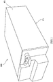
- FIG. 1 is a perspective view showing a casing 100 produced by the casing producing method according to the embodiment of the present invention.
- the casing 100 has a rectangular solid shape. Therefore, the casing 100 is formed such that adjacent surfaces thereof intersect with each other at a right angle.
- the casing 100 accommodates therein a control board of a robot and is configured as a casing for a robot controller that controls the robot.
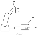
- FIG. 2 is a configuration diagram showing that the casing 100 of the present embodiment is used as a casing for a robot controller that controls a robot 60.
- the casing 100 of the present embodiment accommodates therein a control board 80 configured to control the operation of the robot 60. Therefore, the casing 100 serves as a controller casing that accommodates the control board 80.
- the robot 60 is used as a multiaxial industrial robot.
- the present embodiment describes that the robot controlled by the control board accommodated in the casing is an industrial robot.
- the robot controlled by the control board accommodated in the casing may be a different type of robot.
- the robot may be of any type as long as the robot is controlled by the control board in the casing.
- the control board accommodated in the casing does not have to be a control board configured to control a robot.
- a control board configured to control a thing other than a robot may be accommodated in the casing.
- a thing accommodated in the casing does not have to be a control board.
- the present invention may be applied to a casing that accommodates a thing other than a control board.
- the casing 100 is made of aluminum.
- the casing 100 is used as a robot controller, a large amount of heat is generated from the control board 80 while the robot 60 is operating. Therefore, the casing 100 is made of aluminum having high heat radiation performance.
- the casing 100 having a rectangular solid shape is formed by using a casing forming member 10 having a U-shaped section.
- FIG. 3 is a perspective view showing two parts of the casing forming member 10 constituting the casing 100.
- the casing forming member 10 includes a surface which is located at a lower portion of the casing 100 and is grounded.
- the casing forming member 10 is formed to have a U-shaped section by perpendicularly connecting three plate-shaped portions to each other.
- the casing forming member 10 formed to have a U-shaped section is formed by assembling two L-shaped parts to each other.
- FIG. 4 is a perspective view showing the casing forming member 10 which is divided into two parts (first and second parts) 11 and 12.
- Each of the parts 11 and 12 is formed to have an L-shaped section by connecting two plate-shaped portions (plate portions) such that an angle between main surfaces of the plate portions becomes 90°.
- the part 11 is formed to have an L-shaped section by connecting two plate portions 11a and 11b such that an angle between main surfaces of the plate portions 11a and 11b becomes 90°.
- the two plate portions 11a and 11b are connected to each other such that the angle between the main surfaces thereof becomes 90°.
- the main surfaces of the two plate portions 11a and 11b are outside surfaces of the plate portions 11a and 11b.
- the part 12 is formed to have an L-shaped section by connecting two plate portions 12a and 12b such that an angle between main surfaces of the plate portions 12a and 12b becomes 90°.
- the two plate portions 12a and 12b are connected to each other such that the angle between the main surfaces thereof becomes 90°.
- the main surfaces of the two plate portions 12a and 12b are outside surfaces of the plate portions 12a and 12b.
- a part 30 constituting a portion of the casing forming member 10 and having an L-shaped section is formed by die casting.
- the part 30 is configured to have the L-shaped section by two plate portions 30a and 30b perpendicular to each other.
- FIG. 5 is a sectional view showing a die 50 and the part 30 which is formed by the die casting.
- the die (first die) 50 includes an upper die portion (first die portion) 51 and a lower die portion (second die portion) 52.
- the upper die portion 51 and the lower die portion 52 are configured to be able to approach each other and separate from each other.
- a cavity 53 corresponding to the shape of the part 30 is formed between the upper die portion 51 and the lower die portion 52.
- the cavity 53 is used to form the part 30 by the die casting, the part 30 being formed by the two plate portions 30a and 30b perpendicular to each other.
- molten metal prepared by melting aluminum is poured under pressure into an inside of the cavity 53. After that, the molten metal is cooled and solidified inside the cavity 53. With this, the part 30 is formed. As a result, the part 30 having a shape corresponding to the shape of the cavity 53 and made of aluminum is formed.
- the cavity 53 is formed at the die 50 so as to correspond to the part 30.
- the cavity 53 includes plate-portion cavities 53a and 53b corresponding to the two plate portions 30a and 30b perpendicular to each other.
- the cavity 53 is formed such that an intersection line 1 where main surfaces of the two plate portions 30a and 30b intersect with each other is located at a lowest position in the die 50.
- the cavity 53 is formed such that a position corresponding to the intersection line 1 where the two plate portions intersect with each other is located at the lowest position in the die 50.
- the cavity 53 is formed such that the part 30 is formed to take such a posture that a direction in which the plate portion 30b extends from the intersection line 1 is inclined relative to a horizontal plane.
- the position corresponding to the intersection line 1 where the two plate portions 30a and 30b intersect with each other is located at the lowest position. Furthermore, the cavity 53 is formed such that a direction in which a portion thereof forming the plate portion 30b extends from the intersection line 1 is inclined relative to the horizontal plane.
- the part 30 is formed to take such a posture that the direction in which the plate portion 30b located at a lower side in the die 50 out of the two plate portions 30a and 30b formed at the part 30 extends is inclined relative to the horizontal plane.
- the part 30 is formed to take such a posture that the direction in which the plate portion 30b extends is inclined relative to the horizontal plane at an angle ⁇ that is 1° or more and 2° or less.
- the part 30 is formed to take such a posture that a direction in which the plate portion 30a located at an upper side in the die 50 out of the two plate portions 30a and 30b formed at the part 30 extends is inclined relative to a vertical direction.
- the part 30 is formed to take such a posture that the direction in which the plate portion 30a extends is inclined relative to the vertical direction at the angle ⁇ that is 1° or more and 2° or less.
- each of the angle at which the plate portion 30b is inclined relative to the horizontal plane and the angle ⁇ at which the direction in which the plate portion 30a extends is inclined relative to the vertical direction be 1.5° or more.
- each of the angle at which the plate portion 30b is inclined relative to the horizontal plane and the angle ⁇ at which the direction in which the plate portion 30a extends is inclined relative to the vertical direction be 1° or more and 2° or less.
- FIG. 7 is a flow chart showing a procedure performed when producing the casing 100 by the method of producing the casing 100 according to the present embodiment.
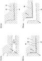
- the upper die portion 51 and the lower die portion 52 in the die 50 are made to approach each other. Then, as shown in FIG. 6B , the upper die portion 51 and the lower die portion 52 are brought into contact with each other. When the upper die portion 51 and the lower die portion 52 contact each other, and therefore, the die 50 is closed, the cavity 53 is formed between the upper die portion 51 and the lower die portion 52.
- molten metal prepared by heating and melting aluminum is poured into an inside of the cavity 53 formed in an inclined state in the die 50.
- the molten metal is poured into the inside of the cavity 53 while being applied with pressure.
- the molten metal is poured under pressure to the inside of the cavity 53 (S1).
- the part 30 is formed to have a shape corresponding to the cavity 53.
- the part 30 having a desired shape is formed in the cavity 53.
- the upper die portion 51 and the lower die portion 52 in the die 50 are separated from each other (S2).
- the part 30 formed between the upper die portion 51 and the lower die portion 52 is taken out from the cavity 53.
- the part 30 is taken out from the cavity 53 while being attached to the upper die portion 51.
- the part 30 is detached from the upper die portion 51, and thus, the part 30 is taken out from the die 50 (S3).
- the die 50 is divided into two portions that are the upper die portion 51 and the lower die portion 52, and the part 30 is formed such that two outside surfaces (main surfaces) of the two plate portions 30a and 30b are formed by only one of the upper die portion 51 and the lower die portion 52.
- the two outside surfaces (main surfaces) of the two plate portions 30a and 30b are formed by the lower die portion 52.
- the part 30 is produced by the die casting.
- a plurality of parts 30 of different types are formed by the die casting, and the part 11 that is one of the parts 30 serves as the part (first part) 11 out of the parts 11 and 12 constituting the casing forming member 10.
- the die that forms the part 11 serves as the die (first die) 50.
- the part 11 that is one of the parts 11 and 12 constituting the casing forming member 10 is formed by the die casting (first part forming step). After the part 11 is formed in the die 50, the part 11 is taken out from the die 50 (S3).
- the part (second part) 12 out of the parts 11 and 12 constituting the casing forming member 10 is formed.
- the part 11 and the part 12 are different in shape from each other. Therefore, when producing the part 12, a die (second die) different from the die (first die) used when producing the part 11 is used. However, since the part 11 and the part 12 are substantially the same in configuration as each other, steps of producing the part 12 are similar to the steps of producing the part 11. Therefore, the part 12 is also produced through the steps shown in FIGS. 6A to 6D .
- the upper die portion (third die portion) and lower die portion (fourth die portion) of the die (second die) are being separated from each other. Then, as shown in FIG. 6B , the upper die portion and lower die portion of the die (second die) are brought into contact with each other, and with this, the cavity is formed therebetween. After the cavity is formed between the upper die portion and lower die portion of the die (second die), as shown in FIG. 6C , the molten metal is poured under pressure into the cavity formed in an inclined state in the die (second die) (S4). After the molten metal is poured under pressure into the die (second die), the die (second die) is cooled.
- the part (second part) is formed.
- the part (second part) is formed in the cavity (second part forming step).
- the upper die portion and lower die portion of the die (second die) are separated from each other (S5).
- the part (second part) formed between the upper die portion and the lower die portion is taken out from the cavity while being attached to the upper die portion.
- the part (second part) is detached from the upper die portion, and thus, the part (second part) is taken out from the die (second die) (S6).
- the present embodiment describes that the two parts 11 and 12 are different in shape from each other. Therefore, the present embodiment describes that the shape of the cavity is different between the die (first die) that forms the part 11 and the die (second die) that forms the part 12.
- the present invention is not limited to the above embodiment.
- the shape of the part 11 (first part) and the shape of the part 12 (second part) may be the same as each other.
- the die that forms the part 11 and the die that forms the part 12 may be common to each other.
- Two parts (third parts) which constitute the casing forming member 10 and are the same in shape as each other may be formed by a common die (third die) including an upper die portion (fifth die portion) and a lower die portion (sixth die portion).
- the two common parts (third parts) are formed by performing the step (third part forming step) of forming the part (third part) twice.
- the two parts (third parts) are produced by the common die, the number of necessary dies can be reduced, and therefore, manufacturing cost for the casing 100 can be reduced.
- the casing forming member 10 is formed by assembling the parts 11 and 12 (casing forming member assembling step) (S7).
- the casing forming member 10 is assembled by fastening the two parts 11 and 12 to each other by screws.
- the casing forming member 10 may be formed by using and assembling these two parts.
- the casing forming member 10 may be assembled by fastening the two common parts to each other by screws.
- the casing forming member 10 is formed by fastening the two parts 11 and 12 to each other.
- the plate portion 11b out of the two plate portions 11a and 11b of the part 11 and the plate portion 12a out of the plate portions 12a and 12b of the part 12 are connected to each other to form a single plate portion 13.
- the casing forming member 10 includes the three plate portions 11a, 13, and 12b.
- the plate portions 11a and 11b constituting the part 11 are connected to each other such that the angle between the main surfaces of the plate portions 11a and 11b becomes 90°. Therefore, the plate portions 11a and 13 are connected to each other such that the angle between the outer surfaces of the plate portions 11a and 13 becomes 90°. Moreover, the plate portions 12a and 12b constituting the part 12 are connected to each other such that the angle between the outside surfaces of the plate portions 12a and 12b becomes 90°. Therefore, the plate portions 11a and 13 are connected to each other such that the angle between the outside surfaces of the plate portions 11a and 13 becomes 90°. On this account, the three plate portions 11a, 13, and 12b constituting the casing forming member 10 are connected to each other to form a U shape such that the angle between the adjacent outside surfaces becomes 90°.
- the casing 100 is formed by using the casing forming member 10 (casing forming step) (S8).
- the casing 100 is formed by attaching the other side surfaces to the casing forming member 10 having a U shape and also attaching to the casing forming member 10 a surface located at an upper side of the casing 100.
- a surface F1 as a bottom surface to be grounded, a surface F2 adjacent to the surface F1, and a surface (not shown) opposed to the surface F2 are integrally formed as the casing forming member 10 by the die casting.
- the casing 100 is formed by attaching surfaces other than the surface F1, the surface F2, and the surface opposed to the surface F2 to the casing forming member 10.
- the casing forming member 10 is formed by assembling the parts 11 and 12 obtained by the die casting, and then, the casing 100 is formed by using the casing forming member 10.
- the casing forming member 10 is formed by assembling the two parts 11 and 12 by a method of fastening the two parts 11 and 12 to each other by screws.
- the present invention is not limited to the above embodiment, and the parts may be assembled by a method other than the method of fastening the parts to each other by screws.
- the parts may be assembled by the other methods, such as adhesion using an adhesive.
- the parts 11 and 12 are formed by the die casting, and the casing forming member 10 is formed by assembling the parts 11 and 12.
- the parts 11 and 12 that are divided parts of the casing forming member 10 are formed by the die casting. Therefore, since the parts 11 and 12 each including two plate portions are produced by the die casting, each of the parts 11 and 12 can be formed in an L shape formed by connecting two plate portions. Moreover, since each of the parts 11 and 12 includes the two plate portions and is formed in an L shape, each of the parts 11 and 12 can be formed by connecting the two plate portions to each other such that the angle between the outside surfaces of the two plate portions is maintained to be 90°.
- the casing 100 is formed by connecting the adjacent outside surfaces such that the angle between the adjacent outside surfaces of the casing forming member 10 becomes 90°. Therefore, in the casing 100, adjacent plate members are connected to each other such that the angle between the outside surfaces becomes 90°. With this, in the casing 100, the angle between the outside surfaces of the adjacent plate members is maintained to be 90°.
- the three plate portions 11a, 13, and 12b constituting the casing forming member 10 are connected to each other such that each of the angle between the outside surfaces of the plate portions 11a and 13 and the angle between the outside surfaces of the plate portions 13 and 12b becomes 90°. Since the angle between the adjacent surfaces of the casing 100 is maintained to be 90°, the casing 100 can be stably arranged even when a grounded surface of the casing 100 is changed. Even when the posture of the casing 100 is changed in accordance with an installation space of the casing 100, the casing 100 can be stably arranged. Therefore, when there is a small space for placing the casing 100, the casing 100 can be arranged by changing the posture in accordance with the small space.
- the casing 100 can be stably arranged by changing the posture in accordance with the installation space. With this, the space for the installation of the casing 100 can be used more efficiently. Moreover, since the casing 100 can be stably arranged, the casing 100 can be prevented from falling down, and therefore, the reliability of the casing 100 can be improved. Thus, when the casing 100 is used as a controller of a robot, the reliability of the controller can be improved.
- the installation space for the casing 100 serving as the controller accommodating the control board 80 may be limited depending on a place where the robot is arranged.
- the casing 100 is required to be arranged within the limited space by changing the posture in accordance with the limited space.
- the casing 100 may be arranged in the installation space by changing the posture of the casing 100 shown in FIG. 1 .
- the casing 100 is arranged such that the surface F1 is grounded.
- the casing 100 may be arranged by changing the posture such that the surface F2 is grounded.
- the casing 100 can be arranged by changing the posture, and therefore, even when the installation space is thin and long, the casing 100 can be arranged in accordance with the thin and long installation space.
- the installation space can be used efficiently.
- the adjacent surfaces of the casing 100 are maintained to be perpendicular to each other, the quality of design surfaces of the casing 100 can be improved.
- the die 50 is divided into the upper die portion 51 and the lower die portion 52, and the part 30 is formed such that the two outside surfaces (main surfaces) of the two plate portions 30a and 30b are formed by only one of the upper die portion 51 and the lower die portion 52. Therefore, the outside surfaces as the main surfaces of the plate portions 30a and 30b are shaped and formed by a single die portion (lower die portion 52). With this, the outside surfaces of the plate portions 30a and 30b can be accurately formed such that the angle between the outside surfaces as the main surfaces of the plate portions 30a and 30b becomes 90°.
- the part 30 is formed in an inclined posture inside the die 50.
- the cavity 53 is formed such that: the intersection line 1 where the outside surfaces of the two plate portions 30a and 30b intersect with each other is located at the lowest position in the die 50; and the part 30 is formed in such a posture that the direction in which the plate portion 30b extends from the intersection line 1 is inclined relative to the horizontal plane. Therefore, the cavity 53 is formed inside the die 50 so as to have a downward convex shape.
- Each of portions of the cavity 53 which portions correspond to the respective plate portions 30a and 30b is configured to have draft. Therefore, although the part 30 produced by the die 50 is formed such that the two plate portions 30a and 30b are perpendicular to each other, the draft used when removing the part 30 from the die 50 is secured.
- the outside surface of the plate portion 30a is inclined relative to the vertical direction, and the outside surface of the plate portion 30b is inclined relative to the horizontal direction, the draft of the part 30 is secured. Therefore, when producing the part 30 by the die casting and taking out the part 30 from the die 50, the part 30 can be smoothly taken out from the die 50.
- the two plate portions of each of the parts 11 and 12 produced by the die casting are maintained to be perpendicular to each other, and therefore, the adjacent plate members of the casing forming member 10 formed by assembling the parts 11 and 12 are maintained to be perpendicular to each other.
- the adjacent plate members of the casing 100 are maintained to be perpendicular to each other.
- the plate members constituting the casing forming member 10 of the casing 100 are maintained to be perpendicular to each other.
- the draft does not have to be formed at the part, and the side surface of the plate portion constituting the part does not have to be formed in a tapered shape. Therefore, the thickness of each plate portion can be made uniform. On this account, the quality of the design surfaces of the casing 100 can be further improved. Moreover, since the thickness of each plate portion constituting the part can be made uniform, a portion where the plate portions are connected to each other and its vicinity can be prevented from becoming thick. Therefore, a larger space can be secured in the vicinity of the portion where the plate portions are connected to each other. With this, accessories and the like can be accommodated in the space in the vicinity of the portion where the plate portions are connected to each other, and thus, a larger number of accessories and the like can be accommodated in the casing. As above, the space in the casing can be used more efficiently.
- the arrangement of the casing may become unstable since the grounded surface of the casing is inclined. Since the casing is arranged in an unstable state, the casing may fall down when contact or vibration occurs while the casing is being arranged.
- the draft used to remove the part from the die 50 is secured while maintaining a state where the plate portions 30a and 30b are perpendicular to each other.
- the angle between the plate portions 30a and 30b is maintained to be 90°, and as a result, the angle between the adjacent surfaces of the casing 100 is maintained to be 90°. Therefore, even when the posture of the casing 100 is changed such that the grounded surface of the casing 100 is changed, the casing 100 can be arranged in a stable state.
- the structure of the die may be changed in order that the angle between the adjacent surfaces is maintained to be 90° without forming the draft.
- Adjacent surfaces of a part may be maintained to be perpendicular to each other by changing conditions and operations of closing and opening of die portions of a die.
- the conditions and operation of the closing and opening of the die portions of the die are changed so as to correspond to a part, and then, the die casting is performed, the shape and operations of the die become complex. Therefore, the manufacturing cost for the die may increase.
- the die 50 is divided into the upper die portion 51 and the lower die portion 52, and the part 30 is formed such that the two outside surfaces (main surfaces) of the two plate portions 30a and 30b are formed by only one of the upper die portion 51 and the lower die portion 52. Since the die 50 is divided into the upper die portion 51 and the lower die portion 52, and the outside surfaces of the plate portions 30a and 30b are accurately formed such that the angle between the outside surfaces as the main surfaces of the plate portions 30a and 30b becomes 90°, the part configured such that the angle between the outside surfaces intersecting with each other becomes 90° can be accurately formed by the die 50 having a simple configuration. Since the configuration of the die 50 can be simplified, the manufacturing cost for the casing 100 can be made low.
- the parts 30 forming the casing 100 are made of aluminum, and as a result, the casing 100 is made of aluminum. Therefore, high heat radiation performance of the casing 100 is maintained.
- the casing 100 accommodates therein the control board 80 configured to control the operation of the robot 60 and is configured as a robot controller. Therefore, a large amount of heat is generated from the control board 80.
- the casing 100 is made of aluminum, the heat generated from the control board 80 is efficiently radiated to an outside of the casing 100. Therefore, influence of the heat on the function of the control board 80 can be made small.
- the casing 100 is made of aluminum, the casing 100 can be reduced in weight. Therefore, the casing 100 can be easily carried.
- the part 30 made of aluminum is produced by the die casting. Therefore, a large number of parts 30 as aluminum products can be produced by the die casting at low cost.
- the casing forming member 10 having a U shape is formed by assembling the parts 30 each having an L shape, and the casing 100 having a box shape is formed by using the casing forming member 10. Therefore, before the L-shaped parts 30 are assembled, work of attaching substrates and accessories can be performed with respect to the part 30. Since the substrates and accessories are attached to the part 30 before the L-shaped parts 30 are assembled, work of attaching the substrates and accessories to the part 30 can be performed in a space that is open upward. Therefore, work of attaching the substrates and accessories to the casing 100 can be easily performed, and assembling work including such attaching work can be easily performed.
- inside surfaces of the casing 100 are subjected to various machining.
- a substrate is attached to an inside of the casing 100, and heat generated by the substrate is transmitted to a side surface of the casing 100 to be absorbed by the casing 100, i.e., a portion of the side surface of the casing 100 is used as a heat sink.
- the shape of the inside of the side surface of the casing 100 may become complex.
- the inside of the side surface of the casing 100 is formed in a complex shape
- a portion of the inside of the side surface of the casing 100 is subjected to machine work in some cases.
- a blade of a cutting machine needs to be inserted into a space surrounded by plate-shaped members and needs to be brought into contact with the inside surface of the plate-shaped member.
- the member is formed in a U shape, a space into which the blade is inserted is limited, and therefore, it may be difficult to insert the blade into the space surrounded by the plate-shaped members.
- the inside surface of the part 30 can be subjected to machining.
- the L-shaped parts 30 constituting the U-shaped casing forming member 10 are not assembled yet.
- the inside surface of the L-shaped part 30 can be subjected to machining in a state where an upper side is open, and the space is not limited.
- the inside surface of the part 30 can be easily and accurately subjected to machining.
- Substrates and accessories are attached to the L-shaped parts 30 which are not assembled yet. Therefore, even when an accessory is attached to the inner side surface of the casing 100, the accessory can be stably attached with a back surface of the part 30 grounded.
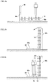
- FIGS. 8A to 8C are side views showing the part 30 in steps performed when attaching accessories to the part 30.
- An example in which two substrates that are upper and lower substrates are attached as the accessories to the part 30 will be described with reference to FIGS. 8A to 8C .
- a substrate 70 arranged at a lower side is attached to the grounded plate portion 30b of the part 30.
- the substrate 70 is attached along the inside surface of the plate portion 30b. At this time, the substrate 70 can be stably attached to the plate portion 30b with the outside surface of the grounded plate portion 30b grounded.
- the grounded surface is changed by changing the posture of the part 30. With this, the plate portion 30b which was grounded when attaching the substrate 70 stands upright, and the plate portion 30a which stood upright when attaching the substrate 70 is grounded.
- a substrate 71 attached at an upper side is attached to the plate portion 30a.
- the substrate 71 is attached along a direction in which the plate portion 30b extends from the side surface of the plate portion 30a. At this time, the substrate 71 can be stably attached to the plate portion 30a with the outside surface of the grounded plate portion 30a grounded.
- the substrate 71 is attached to the plate portion 30a through a supporting portion 72.
- the substrate 71 is attached to the supporting portion 72, and the supporting portion 72 is attached to the plate portion 30a by screws through holes 73 formed on the supporting portion 72. Therefore, the supporting portion 72 can be attached to the plate portion 30a by the screws with the screws perpendicular to the plate portion 30a. Thus, the supporting portion 72 can be stably attached to the plate portion 30a.
- the accessories can be attached to the plate portion 30b with the outside surface of the plate portion 30b grounded. Moreover, accessories can be attached to the inside surface of the plate portion 30a with the outside surface of the plate portion 30a grounded. Therefore, accessories can be stably attached to both plate portions of the L-shaped part 30 with the plate portion grounded. On this account, accessories can be easily attached to the casing 100. Furthermore, accessories can be surely attached to the casing 100, and therefore, the reliability of the casing 100 can be improved.
- the molten metal is prepared by melting aluminum.
- the molten metal may be prepared by a material other than aluminum.
- a different type of molten metal may be used as long as a casing made of metal can be formed.
Landscapes
- Engineering & Computer Science (AREA)
- Mechanical Engineering (AREA)
- Casings For Electric Apparatus (AREA)
- Molds, Cores, And Manufacturing Methods Thereof (AREA)
Abstract

Description
- The present invention relates to a method of producing a casing by die casting.
- In some conventional cases, casings for accommodating control boards are manufactured by die casting.
PTL 1 discloses that the casing for accommodating the control board is manufactured by the die casting. InPTL 1, the casing is manufactured by the die casting using aluminum. - PTL 1: Japanese Laid-Open Patent Application Publication No.
2001-357925 - In
PTL 1, a plurality of parts each having a U shape are manufactured by the die casting, and the casing is manufactured by assembling the manufactured U-shaped parts. - In order to manufacture a part by die casting, a step of removing the manufactured part from a die is required. Typically, when manufacturing a part by die casting, draft needs to be formed at the part such that the part can be removed from the die. Therefore, the part needs to be formed in a tapered shape.
- However, when the part is formed in a tapered shape such that the part can be removed from the die, there is a possibility that adjacent side surfaces of the casing cannot be maintained to be perpendicular to each other. Especially, when a part includes three surfaces, and these three surfaces form a U shape, there is a possibility that adjacent surfaces among the three surfaces of the part cannot be maintained to intersect with each other at a right angle. Therefore, there is a possibility that as a result of the assembling and manufacture of the casing, adjacent surfaces of the casing are not maintained to intersect with each other at a right angle.
- In some cases, the casing that houses the control board is arranged such that a large surface thereof is grounded. Instead, in consideration of an arrangement space, the casing may be arranged by changing the posture thereof such that a small surface thereof is grounded, and the casing stands upright. In such a case, when adjacent surfaces of the casing are not perpendicular to each other, the casing may be arranged in an inclined state. When the casing is arranged in an inclined state, the casing falls down during installation, and the impact by this falling may cause a trouble of the casing.
- The part is formed in a tapered shape so as to be able to be removed from the die. Therefore, when the casing is formed by assembling the parts taken out from the die, opposing inner surfaces of the casing may not be parallel to each other, and an inner space of the casing may be partially narrow. In this case, there is a possibility that since the inner space of the casing is narrow, the capacity inside the casing for accommodation becomes small.
- The present invention was made under these circumstances, and an object of the present invention is to provide a method of producing a casing including adjacent surfaces which are maintained to be perpendicular to each other.
- A method of producing a casing according to the present invention includes: a first part forming step of forming a first part by pouring molten metal into a cavity formed inside a first die including a first die portion and a second die portion, the cavity corresponding to the first part, the first part including two plate portions connected to each other such that an angle between main surfaces of the two plate portions of the first part becomes 90°, the two main surfaces of the two plate portions of the first part being formed by only one of the first die portion and the second die portion; a second part forming step of forming a second part by pouring the molten metal into a cavity formed inside a second die including a third die portion and a fourth die portion, the cavity corresponding to the second part, the second part including two plate portions connected to each other such that an angle between main surfaces of the two plate portions of the second part becomes 90°, the two main surfaces of the two plate portions of the second part being formed by only one of the third die portion and the fourth die portion; a casing forming member assembling step of forming a casing forming member including three plate portions by assembling the first part formed in the first part forming step and the second part formed in the second part forming step; and a casing forming step of forming a casing by using the casing forming member formed in the casing forming member assembling step.
- According to the above method of producing the casing, the first part is formed by the first part forming step of forming the first part by pouring the molten metal into the cavity formed inside the first die including the first die portion and the second die portion, the cavity corresponding to the first part, the first part including the two plate portions connected to each other such that the angle between the main surfaces of the two plate portions of the first part becomes 90°, the two main surfaces of the two plate portions of the first part being formed by only one of the first die portion and the second die portion. Moreover, the second part is formed by the second part forming step of forming the second part by pouring the molten metal into the cavity formed inside the second die including the third die portion and the fourth die portion, the cavity corresponding to the second part, the second part including the two plate portions connected to each other such that the angle between the main surfaces of the two plate portions of the second part becomes 90°, the two main surfaces of the two plate portions of the second part being formed by only one of the third die portion and the fourth die portion. Therefore, the first part and the second part each including the two plate portions connected to each other such that the angle between the main surfaces becomes 90° can be formed. On this account, the casing formed by using these parts is formed such that angle between main surfaces of adjacent surfaces thereof becomes 90°.
- In the first part forming step, the cavity in the first die may be formed such that an intersection line where the main surfaces of the two plate portions of the first part intersect with each other is located at a lowest position inside the first die, and in the second part forming step, the cavity in the second die may be formed such that an intersection line where the main surfaces of the two plate portions of the second part intersect with each other is located at a lowest position inside the second die.
- Since the intersection line where the main surfaces of the two plate portions intersect with each other is located at the lowest position inside each of the first die and the second die, the first part and the second part can be smoothly removed from the first die and the second die.
- In the first part forming step, the cavity in the first die may be provided such that the first part is formed inside the first die in such a posture that a direction in which one of the plate portions of the first part extends from the intersection line is inclined relative to a horizontal plane, and in the second part forming step, the cavity in the second die may be provided such that the second part is formed inside the second die in such a posture that a direction in which one of the plate portions of the second part extends from the intersection line is inclined relative to the horizontal plane.
- Since the first part and the second part are formed inside the first die and the second die in such a posture that the direction in which one of the plate portions extends from the intersection line where the outside surfaces of the two plate portions intersect with each other is inclined relative to the horizontal plane, the first part and the second part can be more smoothly removed from the first die and the second die.
- The molten metal may be prepared by melting aluminum.
- Since the molten metal is prepared by melting aluminum, the casing produced is made of aluminum. Since the casing is made of aluminum, heat generated inside the casing can be efficiently radiated to an outside.
- The casing may be a controller casing accommodating a control board.
- Since the casing is the controller casing accommodating the control board, the controller casing can be formed such that an angle between adjacent outside surfaces thereof becomes a right angle.
- The control board may be a control board configured to control a robot.
- Since the casing is a controller accommodating a control board configured to control a robot, the controller casing accommodating the control board configured to control the robot can be formed such that the angle between adjacent outside surfaces thereof becomes a right angle.
- A method of producing a casing according to the present invention includes: a third part forming step of forming a third part by pouring molten metal into a cavity formed inside a third die including a fifth die portion and a sixth die portion, the cavity corresponding to the third part, the third part including two plate portions connected to each other such that an angle between main surfaces of the two plate portions of the third part becomes 90°, the two main surfaces of the two plate portions of the third part being formed by only one of the fifth die portion and the sixth die portion; a casing forming member assembling step of forming a casing forming member including three plate portions by using and assembling the two third parts formed in the third part forming step; and a casing forming step of forming a casing by using the casing forming member formed in the casing forming member assembling step.
- According to the above method of producing the casing, the third part is formed by the third part forming step of forming the third part by pouring the molten metal into the cavity formed inside the third die including the fifth die portion and the sixth die portion, the cavity corresponding to the third part, the third part including the two plate portions connected to each other such that the angle between the main surfaces of the two plate portions of the third part becomes 90°, the two main surfaces of the two plate portions of the third part being formed by only one of the fifth die portion and the sixth die portion. Moreover, the casing forming member including the three plate portions is formed by using and assembling the two third parts. Therefore, the two third parts each including the two plate portions connected to each other such that the angle between the main surfaces becomes 90° can be formed. On this account, the casing formed by using the two third parts is formed such that the angle between the main surfaces of the adjacent surfaces thereof becomes 90°.
- According to the present invention, the casing formed such that the angle between the main surfaces of the adjacent surfaces thereof becomes 90° is produced. Therefore, the casing which can be stably arranged even when the grounded surface is changed can be provided.
-
-
FIG. 1 is a perspective view of a casing produced by a casing producing method according to an embodiment of the present invention. -
FIG. 2 is a configuration diagram showing a robot and the casing ofFIG. 1 used as a casing for a robot controller. -
FIG. 3 is a perspective view of a casing forming member located at a lower portion of the casing ofFIG. 1 . -
FIG. 4 is a perspective view showing the casing forming member ofFIG. 3 , the casing forming member being divided into two parts. -
FIG. 5 is a sectional view showing a die and a part which constitutes the casing forming member ofFIG. 3 and is formed by die casting. -
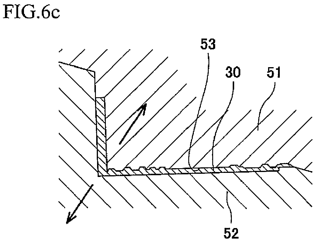
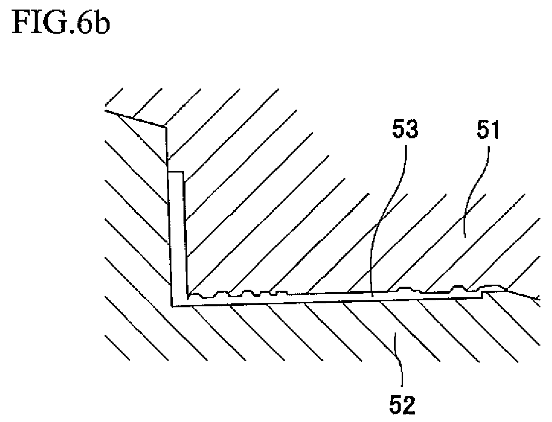
FIGS. 6A to 6D are configuration diagrams showing steps performed when the part constituting the casing forming member ofFIG. 3 is formed by the die casting. -
FIG. 7 is a flow chart showing a procedure performed when producing the casing ofFIG. 1 . -
FIGS. 8A to 8C are side views showing the part, constituting the casing forming member ofFIG. 3 , in steps performed when attaching accessories to an inside of the part. - Hereinafter, a casing producing method according to an embodiment of the present invention will be described with reference to the attached drawings.
-
FIG. 1 is a perspective view showing acasing 100 produced by the casing producing method according to the embodiment of the present invention. - In the present embodiment, the
casing 100 has a rectangular solid shape. Therefore, thecasing 100 is formed such that adjacent surfaces thereof intersect with each other at a right angle. Thecasing 100 accommodates therein a control board of a robot and is configured as a casing for a robot controller that controls the robot. -
FIG. 2 is a configuration diagram showing that thecasing 100 of the present embodiment is used as a casing for a robot controller that controls a robot 60. - As shown in
FIG. 2 , thecasing 100 of the present embodiment accommodates therein acontrol board 80 configured to control the operation of the robot 60. Therefore, thecasing 100 serves as a controller casing that accommodates thecontrol board 80. In the present embodiment, the robot 60 is used as a multiaxial industrial robot. - The present embodiment describes that the robot controlled by the control board accommodated in the casing is an industrial robot. However, the present invention is not limited to the embodiment. The robot controlled by the control board accommodated in the casing may be a different type of robot. The robot may be of any type as long as the robot is controlled by the control board in the casing. Moreover, the control board accommodated in the casing does not have to be a control board configured to control a robot. A control board configured to control a thing other than a robot may be accommodated in the casing. Furthermore, a thing accommodated in the casing does not have to be a control board. The present invention may be applied to a casing that accommodates a thing other than a control board.
- In the present embodiment, the
casing 100 is made of aluminum. When thecasing 100 is used as a robot controller, a large amount of heat is generated from thecontrol board 80 while the robot 60 is operating. Therefore, thecasing 100 is made of aluminum having high heat radiation performance. - In the present embodiment, the
casing 100 having a rectangular solid shape is formed by using acasing forming member 10 having a U-shaped section. -
FIG. 3 is a perspective view showing two parts of thecasing forming member 10 constituting thecasing 100. Thecasing forming member 10 includes a surface which is located at a lower portion of thecasing 100 and is grounded. - The
casing forming member 10 is formed to have a U-shaped section by perpendicularly connecting three plate-shaped portions to each other. Thecasing forming member 10 formed to have a U-shaped section is formed by assembling two L-shaped parts to each other. -
FIG. 4 is a perspective view showing thecasing forming member 10 which is divided into two parts (first and second parts) 11 and 12. - Each of the
parts part 11 is formed to have an L-shaped section by connecting twoplate portions plate portions plate portions plate portions plate portions part 12 is formed to have an L-shaped section by connecting twoplate portions plate portions plate portions plate portions plate portions - Next, a method of producing the
casing 100 will be described. - In the present embodiment, a
part 30 constituting a portion of thecasing forming member 10 and having an L-shaped section is formed by die casting. Thepart 30 is configured to have the L-shaped section by twoplate portions -
FIG. 5 is a sectional view showing adie 50 and thepart 30 which is formed by the die casting. - The die (first die) 50 includes an upper die portion (first die portion) 51 and a lower die portion (second die portion) 52. The
upper die portion 51 and thelower die portion 52 are configured to be able to approach each other and separate from each other. - A
cavity 53 corresponding to the shape of thepart 30 is formed between theupper die portion 51 and thelower die portion 52. Thecavity 53 is used to form thepart 30 by the die casting, thepart 30 being formed by the twoplate portions part 30, molten metal prepared by melting aluminum is poured under pressure into an inside of thecavity 53. After that, the molten metal is cooled and solidified inside thecavity 53. With this, thepart 30 is formed. As a result, thepart 30 having a shape corresponding to the shape of thecavity 53 and made of aluminum is formed. - The
cavity 53 is formed at the die 50 so as to correspond to thepart 30. Thecavity 53 includes plate-portion cavities plate portions cavity 53 is formed such that anintersection line 1 where main surfaces of the twoplate portions die 50. To be specific, thecavity 53 is formed such that a position corresponding to theintersection line 1 where the two plate portions intersect with each other is located at the lowest position in thedie 50. Moreover, thecavity 53 is formed such that thepart 30 is formed to take such a posture that a direction in which theplate portion 30b extends from theintersection line 1 is inclined relative to a horizontal plane. Therefore, in thecavity 53, the position corresponding to theintersection line 1 where the twoplate portions cavity 53 is formed such that a direction in which a portion thereof forming theplate portion 30b extends from theintersection line 1 is inclined relative to the horizontal plane. - Therefore, in the present embodiment, the
part 30 is formed to take such a posture that the direction in which theplate portion 30b located at a lower side in the die 50 out of the twoplate portions part 30 extends is inclined relative to the horizontal plane. In the present embodiment, thepart 30 is formed to take such a posture that the direction in which theplate portion 30b extends is inclined relative to the horizontal plane at an angle α that is 1° or more and 2° or less. - Since the two
plate portions part 30 are perpendicular to each other, thepart 30 is formed to take such a posture that a direction in which theplate portion 30a located at an upper side in the die 50 out of the twoplate portions part 30 extends is inclined relative to a vertical direction. In the present embodiment, thepart 30 is formed to take such a posture that the direction in which theplate portion 30a extends is inclined relative to the vertical direction at the angle α that is 1° or more and 2° or less. Especially, it is desirable that each of the angle at which theplate portion 30b is inclined relative to the horizontal plane and the angle α at which the direction in which theplate portion 30a extends is inclined relative to the vertical direction be 1.5° or more. It should be noted that there is a possibility that if such inclination is large, it is difficult to remove the part from the die due to, for example, the shape of a screw hole formed on the plate portion. Therefore, in the present embodiment, it is preferable that each of the angle at which theplate portion 30b is inclined relative to the horizontal plane and the angle α at which the direction in which theplate portion 30a extends is inclined relative to the vertical direction be 1° or more and 2° or less. - Steps performed when the
part 30 is formed by the die casting will be described with reference toFIGS. 6A to 6D .FIG. 7 is a flow chart showing a procedure performed when producing thecasing 100 by the method of producing thecasing 100 according to the present embodiment. - First, as shown in
FIG. 6A , theupper die portion 51 and thelower die portion 52 in the die 50 are made to approach each other. Then, as shown inFIG. 6B , theupper die portion 51 and thelower die portion 52 are brought into contact with each other. When theupper die portion 51 and thelower die portion 52 contact each other, and therefore, thedie 50 is closed, thecavity 53 is formed between theupper die portion 51 and thelower die portion 52. - As shown in
FIG. 6C , after thecavity 53 is formed, molten metal prepared by heating and melting aluminum is poured into an inside of thecavity 53 formed in an inclined state in thedie 50. In order that the molten metal reaches every corner of thecavity 53, the molten metal is poured into the inside of thecavity 53 while being applied with pressure. Thus, the molten metal is poured under pressure to the inside of the cavity 53 (S1). - When the molten metal is poured under pressure into the inside of the
cavity 53, and then, thedie 50 is cooled, the molten metal is solidified in thedie 50. With this, thepart 30 is formed to have a shape corresponding to thecavity 53. Thus, thepart 30 having a desired shape is formed in thecavity 53. - After the
part 30 is formed in thecavity 53, theupper die portion 51 and thelower die portion 52 in the die 50 are separated from each other (S2). After theupper die portion 51 and thelower die portion 52 are separated from each other, as shown inFIG. 6D , thepart 30 formed between theupper die portion 51 and thelower die portion 52 is taken out from thecavity 53. In the present embodiment, when theupper die portion 51 and thelower die portion 52 are separated from each other, thepart 30 is taken out from thecavity 53 while being attached to theupper die portion 51. After thepart 30 is taken out from thecavity 53, thepart 30 is detached from theupper die portion 51, and thus, thepart 30 is taken out from the die 50 (S3). - At this time, the
die 50 is divided into two portions that are theupper die portion 51 and thelower die portion 52, and thepart 30 is formed such that two outside surfaces (main surfaces) of the twoplate portions upper die portion 51 and thelower die portion 52. In the present embodiment, the two outside surfaces (main surfaces) of the twoplate portions lower die portion 52. - As above, in the present embodiment, the
part 30 is produced by the die casting. In the present embodiment, a plurality ofparts 30 of different types are formed by the die casting, and thepart 11 that is one of theparts 30 serves as the part (first part) 11 out of theparts casing forming member 10. Moreover, the die that forms thepart 11 serves as the die (first die) 50. As above, thepart 11 that is one of theparts casing forming member 10 is formed by the die casting (first part forming step). After thepart 11 is formed in thedie 50, thepart 11 is taken out from the die 50 (S3). - After the
part 11 is formed by the die casting, the part (second part) 12 out of theparts casing forming member 10 is formed. - As shown in
FIG. 4 , thepart 11 and thepart 12 are different in shape from each other. Therefore, when producing thepart 12, a die (second die) different from the die (first die) used when producing thepart 11 is used. However, since thepart 11 and thepart 12 are substantially the same in configuration as each other, steps of producing thepart 12 are similar to the steps of producing thepart 11. Therefore, thepart 12 is also produced through the steps shown inFIGS. 6A to 6D . - To be specific, as shown in
FIG. 6A , the upper die portion (third die portion) and lower die portion (fourth die portion) of the die (second die) are being separated from each other. Then, as shown inFIG. 6B , the upper die portion and lower die portion of the die (second die) are brought into contact with each other, and with this, the cavity is formed therebetween. After the cavity is formed between the upper die portion and lower die portion of the die (second die), as shown inFIG. 6C , the molten metal is poured under pressure into the cavity formed in an inclined state in the die (second die) (S4). After the molten metal is poured under pressure into the die (second die), the die (second die) is cooled. With this, the molten metal is solidified in the die (second die). Thus, the part (second part) is formed. As above, the part (second part) is formed in the cavity (second part forming step). After the part (second part) is formed in the cavity, the upper die portion and lower die portion of the die (second die) are separated from each other (S5). When the upper die portion and the lower die portion are separated from each other, as shown inFIG. 6D , the part (second part) formed between the upper die portion and the lower die portion is taken out from the cavity while being attached to the upper die portion. After the part (second part) is taken out from the cavity, the part (second part) is detached from the upper die portion, and thus, the part (second part) is taken out from the die (second die) (S6). - It should be noted that the present embodiment describes that the two
parts part 11 and the die (second die) that forms thepart 12. However, the present invention is not limited to the above embodiment. The shape of the part 11 (first part) and the shape of the part 12 (second part) may be the same as each other. - In this case, the die that forms the
part 11 and the die that forms thepart 12 may be common to each other. Two parts (third parts) which constitute thecasing forming member 10 and are the same in shape as each other may be formed by a common die (third die) including an upper die portion (fifth die portion) and a lower die portion (sixth die portion). To be specific, the two common parts (third parts) are formed by performing the step (third part forming step) of forming the part (third part) twice. As above, since the two parts (third parts) are produced by the common die, the number of necessary dies can be reduced, and therefore, manufacturing cost for thecasing 100 can be reduced. - After the two
parts casing forming member 10 are formed by the die casting, thecasing forming member 10 is formed by assembling theparts 11 and 12 (casing forming member assembling step) (S7). In the present embodiment, thecasing forming member 10 is assembled by fastening the twoparts - When two parts are formed by a common die, the
casing forming member 10 may be formed by using and assembling these two parts. In this case, thecasing forming member 10 may be assembled by fastening the two common parts to each other by screws. - The
casing forming member 10 is formed by fastening the twoparts plate portion 11b out of the twoplate portions part 11 and theplate portion 12a out of theplate portions part 12 are connected to each other to form asingle plate portion 13. As a result, thecasing forming member 10 includes the threeplate portions - The
plate portions part 11 are connected to each other such that the angle between the main surfaces of theplate portions plate portions plate portions plate portions part 12 are connected to each other such that the angle between the outside surfaces of theplate portions plate portions plate portions plate portions casing forming member 10 are connected to each other to form a U shape such that the angle between the adjacent outside surfaces becomes 90°. - After the
casing forming member 10 is formed, thecasing 100 is formed by using the casing forming member 10 (casing forming step) (S8). In the present embodiment, thecasing 100 is formed by attaching the other side surfaces to thecasing forming member 10 having a U shape and also attaching to the casing forming member 10 a surface located at an upper side of thecasing 100. - As shown in
FIG. 1 , in thecasing 100, a surface F1 as a bottom surface to be grounded, a surface F2 adjacent to the surface F1, and a surface (not shown) opposed to the surface F2 are integrally formed as thecasing forming member 10 by the die casting. Thecasing 100 is formed by attaching surfaces other than the surface F1, the surface F2, and the surface opposed to the surface F2 to thecasing forming member 10. - As above, the
casing forming member 10 is formed by assembling theparts casing 100 is formed by using thecasing forming member 10. - The above embodiment describes that the
casing forming member 10 is formed by assembling the twoparts parts - According to the present embodiment, the
parts casing forming member 10 is formed by assembling theparts parts casing forming member 10 are formed by the die casting. Therefore, since theparts parts parts parts casing 100 is formed by connecting the adjacent outside surfaces such that the angle between the adjacent outside surfaces of thecasing forming member 10 becomes 90°. Therefore, in thecasing 100, adjacent plate members are connected to each other such that the angle between the outside surfaces becomes 90°. With this, in thecasing 100, the angle between the outside surfaces of the adjacent plate members is maintained to be 90°. - Especially, the three
plate portions casing forming member 10 are connected to each other such that each of the angle between the outside surfaces of theplate portions plate portions casing 100 is maintained to be 90°, thecasing 100 can be stably arranged even when a grounded surface of thecasing 100 is changed. Even when the posture of thecasing 100 is changed in accordance with an installation space of thecasing 100, thecasing 100 can be stably arranged. Therefore, when there is a small space for placing thecasing 100, thecasing 100 can be arranged by changing the posture in accordance with the small space. For example, even when there is only a thin, long, and narrow installation space, thecasing 100 can be stably arranged by changing the posture in accordance with the installation space. With this, the space for the installation of thecasing 100 can be used more efficiently. Moreover, since thecasing 100 can be stably arranged, thecasing 100 can be prevented from falling down, and therefore, the reliability of thecasing 100 can be improved. Thus, when thecasing 100 is used as a controller of a robot, the reliability of the controller can be improved. - Especially, the installation space for the
casing 100 serving as the controller accommodating thecontrol board 80 may be limited depending on a place where the robot is arranged. In such a case, thecasing 100 is required to be arranged within the limited space by changing the posture in accordance with the limited space. For example, when the installation space has a thin and long shape, thecasing 100 may be arranged in the installation space by changing the posture of thecasing 100 shown inFIG. 1 . InFIG. 1 , thecasing 100 is arranged such that the surface F1 is grounded. However, thecasing 100 may be arranged by changing the posture such that the surface F2 is grounded. As above, thecasing 100 can be arranged by changing the posture, and therefore, even when the installation space is thin and long, thecasing 100 can be arranged in accordance with the thin and long installation space. Thus, the installation space can be used efficiently. - Moreover, since the adjacent surfaces of the
casing 100 are maintained to be perpendicular to each other, the quality of design surfaces of thecasing 100 can be improved. - In the present embodiment, the
die 50 is divided into theupper die portion 51 and thelower die portion 52, and thepart 30 is formed such that the two outside surfaces (main surfaces) of the twoplate portions upper die portion 51 and thelower die portion 52. Therefore, the outside surfaces as the main surfaces of theplate portions plate portions plate portions - Moreover, the
part 30 is formed in an inclined posture inside thedie 50. Thecavity 53 is formed such that: theintersection line 1 where the outside surfaces of the twoplate portions die 50; and thepart 30 is formed in such a posture that the direction in which theplate portion 30b extends from theintersection line 1 is inclined relative to the horizontal plane. Therefore, thecavity 53 is formed inside the die 50 so as to have a downward convex shape. Each of portions of thecavity 53 which portions correspond to therespective plate portions part 30 produced by thedie 50 is formed such that the twoplate portions part 30 from thedie 50 is secured. Since the outside surface of theplate portion 30a is inclined relative to the vertical direction, and the outside surface of theplate portion 30b is inclined relative to the horizontal direction, the draft of thepart 30 is secured. Therefore, when producing thepart 30 by the die casting and taking out thepart 30 from thedie 50, thepart 30 can be smoothly taken out from thedie 50. - In addition to the outside surfaces, the two plate portions of each of the
parts casing forming member 10 formed by assembling theparts casing 100 is assembled, the adjacent plate members of thecasing 100 are maintained to be perpendicular to each other. At this time, the plate members constituting thecasing forming member 10 of thecasing 100 are maintained to be perpendicular to each other. - In the present embodiment, the draft does not have to be formed at the part, and the side surface of the plate portion constituting the part does not have to be formed in a tapered shape. Therefore, the thickness of each plate portion can be made uniform. On this account, the quality of the design surfaces of the
casing 100 can be further improved. Moreover, since the thickness of each plate portion constituting the part can be made uniform, a portion where the plate portions are connected to each other and its vicinity can be prevented from becoming thick. Therefore, a larger space can be secured in the vicinity of the portion where the plate portions are connected to each other. With this, accessories and the like can be accommodated in the space in the vicinity of the portion where the plate portions are connected to each other, and thus, a larger number of accessories and the like can be accommodated in the casing. As above, the space in the casing can be used more efficiently. - Typically, when the casing is used as a controller of a robot, there is a high possibility that the casing becomes relatively large. According to a small casing, even when the angle between the adjacent surfaces of the casing deviates from 90° due to the formation of the draft used when removing a part from the die, influence caused by this is small, and therefore, is not problematic. However, according to a large casing, even when the angle between the adjacent surfaces slightly deviates from 90°, influence caused by this is large. According to the large casing, even when the angle between the adjacent surfaces slightly deviates from 90°, a gradient generated by this deviation becomes large, and therefore, a difference in height between end portions of opposing surfaces becomes large. On this account, when the posture of the casing is changed by changing the grounded surface, the arrangement of the casing may become unstable since the grounded surface of the casing is inclined. Since the casing is arranged in an unstable state, the casing may fall down when contact or vibration occurs while the casing is being arranged.
- In some conventional cases, when producing a relatively large casing by die casting, a portion projecting due to the deviation of an angle between adjacent surfaces from a right angle by the formation of draft is eliminated by being cut. With this, the casing configured such that the angle between the adjacent surfaces is maintained to be 90° can be produced. However, according to this method of eliminating such projecting portion by cutting, a step of eliminating the projecting portion of the casing is required, and therefore, extra labor is required. Moreover, since the eliminated portion is wastefully discarded, a larger amount of material is required, and this increases manufacturing cost for the larger amount of material.
- Even when the
casing 100 of the present embodiment is large, the draft used to remove the part from thedie 50 is secured while maintaining a state where theplate portions plate portions casing 100 is maintained to be 90°. Therefore, even when the posture of thecasing 100 is changed such that the grounded surface of thecasing 100 is changed, thecasing 100 can be arranged in a stable state. - Furthermore, the structure of the die may be changed in order that the angle between the adjacent surfaces is maintained to be 90° without forming the draft. Adjacent surfaces of a part may be maintained to be perpendicular to each other by changing conditions and operations of closing and opening of die portions of a die. However, when the conditions and operation of the closing and opening of the die portions of the die are changed so as to correspond to a part, and then, the die casting is performed, the shape and operations of the die become complex. Therefore, the manufacturing cost for the die may increase.
- In the present embodiment, the
die 50 is divided into theupper die portion 51 and thelower die portion 52, and thepart 30 is formed such that the two outside surfaces (main surfaces) of the twoplate portions upper die portion 51 and thelower die portion 52. Since thedie 50 is divided into theupper die portion 51 and thelower die portion 52, and the outside surfaces of theplate portions plate portions casing 100 can be made low. - In the present embodiment, the
parts 30 forming thecasing 100 are made of aluminum, and as a result, thecasing 100 is made of aluminum. Therefore, high heat radiation performance of thecasing 100 is maintained. - In the present embodiment, the
casing 100 accommodates therein thecontrol board 80 configured to control the operation of the robot 60 and is configured as a robot controller. Therefore, a large amount of heat is generated from thecontrol board 80. In the present embodiment, since thecasing 100 is made of aluminum, the heat generated from thecontrol board 80 is efficiently radiated to an outside of thecasing 100. Therefore, influence of the heat on the function of thecontrol board 80 can be made small. - Moreover, since the
casing 100 is made of aluminum, thecasing 100 can be reduced in weight. Therefore, thecasing 100 can be easily carried. - In the present embodiment, the
part 30 made of aluminum is produced by the die casting. Therefore, a large number ofparts 30 as aluminum products can be produced by the die casting at low cost. - The
casing forming member 10 having a U shape is formed by assembling theparts 30 each having an L shape, and thecasing 100 having a box shape is formed by using thecasing forming member 10. Therefore, before the L-shapedparts 30 are assembled, work of attaching substrates and accessories can be performed with respect to thepart 30. Since the substrates and accessories are attached to thepart 30 before the L-shapedparts 30 are assembled, work of attaching the substrates and accessories to thepart 30 can be performed in a space that is open upward. Therefore, work of attaching the substrates and accessories to thecasing 100 can be easily performed, and assembling work including such attaching work can be easily performed. - In the present embodiment, as shown in
FIG. 4 , inside surfaces of thecasing 100 are subjected to various machining. Especially when thecasing 100 is used as a controller of a robot, in some cases, a substrate is attached to an inside of thecasing 100, and heat generated by the substrate is transmitted to a side surface of thecasing 100 to be absorbed by thecasing 100, i.e., a portion of the side surface of thecasing 100 is used as a heat sink. In such cases, since a portion on which the substrate is mounted and a portion which serves as the heat sink are formed on an inside of the side surface of thecasing 100, the shape of the inside of the side surface of thecasing 100 may become complex. - As above, when the inside of the side surface of the
casing 100 is formed in a complex shape, a portion of the inside of the side surface of thecasing 100 is subjected to machine work in some cases. When subjecting the inside surface of thecasing 100 to machine work such that the inside surface has a complex shape, a blade of a cutting machine needs to be inserted into a space surrounded by plate-shaped members and needs to be brought into contact with the inside surface of the plate-shaped member. When the member is formed in a U shape, a space into which the blade is inserted is limited, and therefore, it may be difficult to insert the blade into the space surrounded by the plate-shaped members. - In the present embodiment, the inside surface of the
part 30 can be subjected to machining. In the present embodiment, in the middle of the production of thecasing 100, the L-shapedparts 30 constituting the U-shapedcasing forming member 10 are not assembled yet. Thus, the inside surface of the L-shapedpart 30 can be subjected to machining in a state where an upper side is open, and the space is not limited. On this account, the inside surface of thepart 30 can be easily and accurately subjected to machining. - Substrates and accessories are attached to the L-shaped
parts 30 which are not assembled yet. Therefore, even when an accessory is attached to the inner side surface of thecasing 100, the accessory can be stably attached with a back surface of thepart 30 grounded. -
FIGS. 8A to 8C are side views showing thepart 30 in steps performed when attaching accessories to thepart 30. An example in which two substrates that are upper and lower substrates are attached as the accessories to thepart 30 will be described with reference toFIGS. 8A to 8C . - First, as shown in
FIG. 8A , asubstrate 70 arranged at a lower side is attached to the groundedplate portion 30b of thepart 30. Thesubstrate 70 is attached along the inside surface of theplate portion 30b. At this time, thesubstrate 70 can be stably attached to theplate portion 30b with the outside surface of the groundedplate portion 30b grounded. - After the
substrate 70 is attached to the groundedplate portion 30b, as shown inFIG. 8B , the grounded surface is changed by changing the posture of thepart 30. With this, theplate portion 30b which was grounded when attaching thesubstrate 70 stands upright, and theplate portion 30a which stood upright when attaching thesubstrate 70 is grounded. - When the
plate portion 30a is grounded by changing the posture of thepart 30, asubstrate 71 attached at an upper side is attached to theplate portion 30a. Thesubstrate 71 is attached along a direction in which theplate portion 30b extends from the side surface of theplate portion 30a. At this time, thesubstrate 71 can be stably attached to theplate portion 30a with the outside surface of the groundedplate portion 30a grounded. - In the present embodiment, the
substrate 71 is attached to theplate portion 30a through a supportingportion 72. Thesubstrate 71 is attached to the supportingportion 72, and the supportingportion 72 is attached to theplate portion 30a by screws throughholes 73 formed on the supportingportion 72. Therefore, the supportingportion 72 can be attached to theplate portion 30a by the screws with the screws perpendicular to theplate portion 30a. Thus, the supportingportion 72 can be stably attached to theplate portion 30a. - As above, in the present embodiment, since accessories are attached to the L-shaped
part 30, the accessories can be attached to theplate portion 30b with the outside surface of theplate portion 30b grounded. Moreover, accessories can be attached to the inside surface of theplate portion 30a with the outside surface of theplate portion 30a grounded. Therefore, accessories can be stably attached to both plate portions of the L-shapedpart 30 with the plate portion grounded. On this account, accessories can be easily attached to thecasing 100. Furthermore, accessories can be surely attached to thecasing 100, and therefore, the reliability of thecasing 100 can be improved. - The above embodiment has described that the molten metal is prepared by melting aluminum. However, the present invention is not limited to the above embodiment. The molten metal may be prepared by a material other than aluminum. A different type of molten metal may be used as long as a casing made of metal can be formed.
-
- 30
- part
- 30a, 30b
- plate portion
- 50
- die
- 53
- cavity
- 100
- casing
Claims (7)
- A method of producing a casing,
the method comprising:a first part forming step of forming a first part by pouring molten metal into a cavity formed inside a first die including a first die portion and a second die portion, the cavity corresponding to the first part, the first part including two plate portions connected to each other such that an angle between main surfaces of the two plate portions of the first part becomes 90°, the two main surfaces of the two plate portions of the first part being formed by only one of the first die portion and the second die portion;a second part forming step of forming a second part by pouring the molten metal into a cavity formed inside a second die including a third die portion and a fourth die portion, the cavity corresponding to the second part, the second part including two plate portions connected to each other such that an angle between main surfaces of the two plate portions of the second part becomes 90°, the two main surfaces of the two plate portions of the second part being formed by only one of the third die portion and the fourth die portion;a casing forming member assembling step of forming a casing forming member including three plate portions by assembling the first part formed in the first part forming step and the second part formed in the second part forming step; anda casing forming step of forming a casing by using the casing forming member formed in the casing forming member assembling step. - The method according to claim 1, wherein:in the first part forming step, the cavity in the first die is formed such that an intersection line where the main surfaces of the two plate portions of the first part intersect with each other is located at a lowest position inside the first die; andin the second part forming step, the cavity in the second die is formed such that an intersection line where the main surfaces of the two plate portions of the second part intersect with each other is located at a lowest position inside the second die.
- The method according to claim 2, wherein:in the first part forming step, the cavity in the first die is provided such that the first part is formed inside the first die in such a posture that a direction in which one of the plate portions of the first part extends from the intersection line is inclined relative to a horizontal plane; andin the second part forming step, the cavity in the second die is provided such that the second part is formed inside the second die in such a posture that a direction in which one of the plate portions of the second part extends from the intersection line is inclined relative to the horizontal plane.
- The method according to any one of claims 1 to 3, wherein the molten metal is prepared by melting aluminum.
- The method according to any one of claims 1 to 3, wherein the casing is a controller casing accommodating a control board.
- The method according to claim 5, wherein the control board is a control board configured to control a robot.
- A method of producing a casing,
the method comprising:a third part forming step of forming a third part by pouring molten metal into a cavity formed inside a third die including a fifth die portion and a sixth die portion, the cavity corresponding to the third part, the third part including two plate portions connected to each other such that an angle between main surfaces of the two plate portions of the third part becomes 90°, the two main surfaces of the two plate portions of the third part being formed by only one of the fifth die portion and the sixth die portion;a casing forming member assembling step of forming a casing forming member including three plate portions by using and assembling the two third parts formed in the third part forming step; anda casing forming step of forming a casing by using the casing forming member formed in the casing forming member assembling step.
Applications Claiming Priority (2)
| Application Number | Priority Date | Filing Date | Title |
|---|---|---|---|
| JP2018017798A JP7045872B2 (en) | 2018-02-05 | 2018-02-05 | How to make the housing |
| PCT/JP2019/003557 WO2019151466A1 (en) | 2018-02-05 | 2019-02-01 | Method of manufacturing housing |
Publications (2)
| Publication Number | Publication Date |
|---|---|
| EP3750650A1 true EP3750650A1 (en) | 2020-12-16 |
| EP3750650A4 EP3750650A4 (en) | 2021-06-23 |
Family
ID=67478404
Family Applications (1)
| Application Number | Title | Priority Date | Filing Date |
|---|---|---|---|
| EP19748250.8A Withdrawn EP3750650A4 (en) | 2018-02-05 | 2019-02-01 | CASE MANUFACTURING PROCESS |
Country Status (7)
| Country | Link |
|---|---|
| US (1) | US20210213518A1 (en) |
| EP (1) | EP3750650A4 (en) |
| JP (1) | JP7045872B2 (en) |
| KR (1) | KR102399498B1 (en) |
| CN (1) | CN111683767B (en) |
| TW (1) | TWI706818B (en) |
| WO (1) | WO2019151466A1 (en) |
Family Cites Families (16)
| Publication number | Priority date | Publication date | Assignee | Title |
|---|---|---|---|---|
| JPS614859U (en) * | 1984-06-13 | 1986-01-13 | 株式会社日立製作所 | Mold without punching scent |
| JP2778651B2 (en) * | 1990-03-15 | 1998-07-23 | オリンパス光学工業株式会社 | Injection mold |
| JPH08442Y2 (en) * | 1993-03-24 | 1996-01-10 | ニッコー株式会社 | Unit room |
| JP3021296B2 (en) * | 1994-09-13 | 2000-03-15 | 株式会社デンソー | Box for electronic device, method of manufacturing the same, and method of using the same |
| FR2734524B1 (en) * | 1995-05-23 | 1997-07-25 | Faure Bertrand Equipements Sa | PROFILED FRAME FOR AUTOMOBILE SEAT |
| JP2001113353A (en) * | 1999-10-15 | 2001-04-24 | Fujitsu Kasei Kk | Injection molding mold equipment for magnesium alloy |
| US6276963B1 (en) | 2000-04-19 | 2001-08-21 | Molex Incorporated | Adapter frame assembly for electrical connectors |
| JP3617958B2 (en) * | 2001-03-07 | 2005-02-09 | 株式会社東芝 | Housing for display device |
| CN100467318C (en) * | 2003-12-11 | 2009-03-11 | 株洲时代集团公司 | A skeleton jigsaw type electric locomotive electrical cabinet box |
| FR2866194B1 (en) * | 2004-02-10 | 2006-03-24 | Schneider Electric Ind Sas | BOX COVER |
| DE102006006313B4 (en) * | 2006-02-08 | 2008-05-21 | Schunk Kohlenstofftechnik Gmbh | Method and device for producing a multilayer molded article |
| JP2007326114A (en) * | 2006-06-06 | 2007-12-20 | Kyocera Chemical Corp | Die apparatus for casting and method for manufacturing casting |
| JP4491041B1 (en) * | 2009-05-11 | 2010-06-30 | 日本省力機械株式会社 | Resin product manufacturing system and manufacturing method |
| JP6785584B2 (en) * | 2016-06-15 | 2020-11-18 | 株式会社デンソーテン | Die-cast molded product |
| CN107404818B (en) * | 2017-07-24 | 2019-08-09 | 广东长盈精密技术有限公司 | Shell, shell manufacturing method and mobile terminal |
| CN107363227A (en) * | 2017-07-26 | 2017-11-21 | 江苏雷科德轨道交通科技有限公司 | Gear case body casting manufacture craft |
-
2018
- 2018-02-05 JP JP2018017798A patent/JP7045872B2/en active Active
-
2019
- 2019-02-01 EP EP19748250.8A patent/EP3750650A4/en not_active Withdrawn
- 2019-02-01 CN CN201980011320.8A patent/CN111683767B/en active Active
- 2019-02-01 US US16/967,541 patent/US20210213518A1/en not_active Abandoned
- 2019-02-01 WO PCT/JP2019/003557 patent/WO2019151466A1/en not_active Ceased
- 2019-02-01 TW TW108104261A patent/TWI706818B/en active
- 2019-02-01 KR KR1020207025130A patent/KR102399498B1/en active Active
Also Published As
| Publication number | Publication date |
|---|---|
| JP7045872B2 (en) | 2022-04-01 |
| JP2019135057A (en) | 2019-08-15 |
| TW201936293A (en) | 2019-09-16 |
| KR102399498B1 (en) | 2022-05-18 |
| CN111683767A (en) | 2020-09-18 |
| EP3750650A4 (en) | 2021-06-23 |
| WO2019151466A1 (en) | 2019-08-08 |
| TWI706818B (en) | 2020-10-11 |
| KR20200111256A (en) | 2020-09-28 |
| CN111683767B (en) | 2022-01-14 |
| US20210213518A1 (en) | 2021-07-15 |
Similar Documents
| Publication | Publication Date | Title |
|---|---|---|
| CN103153532B (en) | For the production of process equipment and/or the support module of build-up member and the process equipment being equipped with such support module | |
| US20180200800A1 (en) | Thermal expansion fit build plate for additive manufacturing | |
| US20110229305A1 (en) | Cover plate for turbine vane assembly | |
| JP5664929B2 (en) | Electrical junction box | |
| JP2015208124A (en) | Insert bus bar plate and manufacturing method thereof | |
| JP7086545B2 (en) | Support removal tool for additive manufacturing | |
| JP5621217B2 (en) | Electronic module manufacturing method, electronic module, and vehicle | |
| JP6799118B2 (en) | Equipment for additionally manufacturing three-dimensional objects | |
| US20210213518A1 (en) | Method of producing casing | |
| KR101328125B1 (en) | Component Mount and Protective Case | |
| RU2414813C2 (en) | Rigid and light housing of electronic equipment | |
| US6570089B1 (en) | Automotive electronics control module enclosure | |
| US20110033657A1 (en) | Metal shell manufacturing structure and method | |
| WO1999067979A1 (en) | Electronic apparatus, method of manufacturing electronic apparatus case and blanking device | |
| CN114226647B (en) | Casting device and sand box | |
| US20160265472A1 (en) | Cylinder block and manufacturing method thereof | |
| CN103166386A (en) | Device for manufacturing field pole used magnet and manufacturing method thereof | |
| KR101319077B1 (en) | Zig for attaching reinforcement to fpcb | |
| WO2009110833A1 (en) | A mould and a method of its manufacture | |
| JP2018176201A (en) | Method for manufacturing casting using casting model and casting model | |
| JP4139754B2 (en) | Casting method | |
| CN119789348A (en) | Shell, preparation method thereof and electronic equipment | |
| JP6629588B2 (en) | Die-casting mold, cast product produced using die-casting mold, and method for producing cast product using die-casting mold | |
| JP6870380B2 (en) | Molded product, mold structure and manufacturing method of mold molded product | |
| JPH01321697A (en) | Assembly method of electronic device with printed circuit board and its structure |
Legal Events
| Date | Code | Title | Description |
|---|---|---|---|
| STAA | Information on the status of an ep patent application or granted ep patent |
Free format text: STATUS: THE INTERNATIONAL PUBLICATION HAS BEEN MADE |
|
| PUAI | Public reference made under article 153(3) epc to a published international application that has entered the european phase |
Free format text: ORIGINAL CODE: 0009012 |
|
| STAA | Information on the status of an ep patent application or granted ep patent |
Free format text: STATUS: REQUEST FOR EXAMINATION WAS MADE |
|
| 17P | Request for examination filed |
Effective date: 20200727 |
|
| AK | Designated contracting states |
Kind code of ref document: A1 Designated state(s): AL AT BE BG CH CY CZ DE DK EE ES FI FR GB GR HR HU IE IS IT LI LT LU LV MC MK MT NL NO PL PT RO RS SE SI SK SM TR |
|
| AX | Request for extension of the european patent |
Extension state: BA ME |
|
| DAV | Request for validation of the european patent (deleted) | ||
| DAX | Request for extension of the european patent (deleted) | ||
| A4 | Supplementary search report drawn up and despatched |
Effective date: 20210521 |
|
| RIC1 | Information provided on ipc code assigned before grant |
Ipc: B22D 17/00 20060101AFI20210517BHEP Ipc: B22C 9/06 20060101ALI20210517BHEP Ipc: B22D 17/22 20060101ALI20210517BHEP Ipc: B22C 9/22 20060101ALI20210517BHEP Ipc: B22D 21/00 20060101ALI20210517BHEP Ipc: B22D 21/04 20060101ALI20210517BHEP |
|
| STAA | Information on the status of an ep patent application or granted ep patent |
Free format text: STATUS: EXAMINATION IS IN PROGRESS |
|
| 17Q | First examination report despatched |
Effective date: 20220405 |
|
| STAA | Information on the status of an ep patent application or granted ep patent |
Free format text: STATUS: THE APPLICATION IS DEEMED TO BE WITHDRAWN |
|
| 18D | Application deemed to be withdrawn |
Effective date: 20230321 |