EP3750426A1 - Système et procédé de gestion d'un dispositif de substitution du tabac - Google Patents
Système et procédé de gestion d'un dispositif de substitution du tabac Download PDFInfo
- Publication number
- EP3750426A1 EP3750426A1 EP19179932.9A EP19179932A EP3750426A1 EP 3750426 A1 EP3750426 A1 EP 3750426A1 EP 19179932 A EP19179932 A EP 19179932A EP 3750426 A1 EP3750426 A1 EP 3750426A1
- Authority
- EP
- European Patent Office
- Prior art keywords
- smoking substitute
- consumable
- mode
- substitute device
- coupling portion
- Prior art date
- Legal status (The legal status is an assumption and is not a legal conclusion. Google has not performed a legal analysis and makes no representation as to the accuracy of the status listed.)
- Ceased
Links
Images

Classifications
-
- A—HUMAN NECESSITIES
- A24—TOBACCO; CIGARS; CIGARETTES; SIMULATED SMOKING DEVICES; SMOKERS' REQUISITES
- A24F—SMOKERS' REQUISITES; MATCH BOXES; SIMULATED SMOKING DEVICES
- A24F40/00—Electrically operated smoking devices; Component parts thereof; Manufacture thereof; Maintenance or testing thereof; Charging means specially adapted therefor
- A24F40/50—Control or monitoring
-
- A—HUMAN NECESSITIES
- A24—TOBACCO; CIGARS; CIGARETTES; SIMULATED SMOKING DEVICES; SMOKERS' REQUISITES
- A24F—SMOKERS' REQUISITES; MATCH BOXES; SIMULATED SMOKING DEVICES
- A24F40/00—Electrically operated smoking devices; Component parts thereof; Manufacture thereof; Maintenance or testing thereof; Charging means specially adapted therefor
- A24F40/10—Devices using liquid inhalable precursors
-
- A—HUMAN NECESSITIES
- A24—TOBACCO; CIGARS; CIGARETTES; SIMULATED SMOKING DEVICES; SMOKERS' REQUISITES
- A24F—SMOKERS' REQUISITES; MATCH BOXES; SIMULATED SMOKING DEVICES
- A24F40/00—Electrically operated smoking devices; Component parts thereof; Manufacture thereof; Maintenance or testing thereof; Charging means specially adapted therefor
- A24F40/50—Control or monitoring
- A24F40/53—Monitoring, e.g. fault detection
Definitions
- the present invention relates to smoking substitute devices.
- it relates to the management of power supply to components of smoking substitute devices.
- the smoking of tobacco is generally considered to expose a smoker to potentially harmful substances. It is generally thought that a significant amount of the potentially harmful substances are generated through the heat caused by the burning and/or combustion of the tobacco and the constituents of the burnt tobacco in the tobacco smoke itself.
- Conventional combustible smoking articles such as cigarettes, typically comprise a cylindrical rod of tobacco comprising shreds of tobacco which is surrounded by a wrapper, and usually also a cylindrical filter axially aligned in an abutting relationship with the wrapped tobacco rod.
- the filter typically comprises a filtration material which is circumscribed by a plug wrap.
- the wrapped tobacco rod and the filter are joined together by a wrapped band of tipping paper that circumscribes the entire length of the filter and an adjacent portion of the wrapped tobacco rod.
- a conventional cigarette of this type is used by lighting the end opposite to the filter, and burning the tobacco rod. The smoker receives mainstream smoke into their mouth by drawing on the mouth end or filter end of the cigarette.
- Such smoking substitute devices can form part of nicotine replacement therapies aimed at people who wish to stop smoking and overcome a dependence on nicotine.
- Smoking substitute devices may comprise electronic systems that permit a user to simulate the act of smoking by producing an aerosol (also referred to as a "vapour") that is drawn into the lungs through the mouth (inhaled) and then exhaled.
- aerosol also referred to as a "vapour”
- the inhaled aerosol typically bears nicotine and/or flavourings without, or with fewer of, the odour and health risks associated with traditional smoking.
- smoking substitute devices are intended to provide a substitute for the rituals of smoking, whilst providing the user with a similar experience and satisfaction to those experienced with traditional smoking and tobacco products.
- Some smoking substitute systems use smoking substitute articles (also referred to as a "consumables”) that are designed to resemble a traditional cigarette and are cylindrical in form with a mouthpiece at one end.
- smoking substitute devices are designed to resemble a traditional cigarette and are cylindrical in form with a mouthpiece at one end. Other smoking substitute devices do not generally resemble a cigarette (for example, the smoking substitute device may have a generally box-like form).
- a smoking substitute approach corresponds to the manner in which the substitute system operates for a user.
- vaping in which a vapourisable liquid, typically referred to (and referred to herein) as “e-liquid”, is heated by a heating device to produce an aerosol vapour which is inhaled by a user.
- An e-liquid typically includes a base liquid as well as nicotine and/or flavourings.
- the resulting vapour therefore typically contains nicotine and/or flavourings.
- the base liquid may include propylene glycol and/or vegetable glycerin.
- a typical vaping smoking substitute device includes a mouthpiece, a power source (typically a battery), a tank for containing e-liquid, as well as a heating device.
- a power source typically a battery
- a tank for containing e-liquid as well as a heating device.
- electrical energy is supplied from the power source to the heating device, which heats the e-liquid to produce an aerosol (or "vapour") which is inhaled by a user through the mouthpiece.
- Vaping smoking substitute devices can be configured in a variety of ways.
- there are "closed system" vaping smoking substitute devices which typically have a sealed tank and heating element which is pre-filled with e-liquid and is not intended to be refilled by an end user.
- One subset of closed system vaping smoking substitute devices include a main body which includes the power source, wherein the main body is configured to be physically and electrically coupled to a consumable including the tank and the heating element. In this way, when the tank of a consumable has been emptied, the main body can be reused by connecting it to a new consumable.
- Another subset of closed system vaping smoking substitute devices are completely disposable, and intended for one-use only.
- vaping smoking substitute devices which typically have a tank that is configured to be refilled by a user, so the device can be used multiple times.
- An example vaping smoking substitute device is the mybluTM e-cigarette.
- the mybluTM e-cigarette is a closed system device which includes a main body and a consumable.
- the main body and consumable are physically and electrically coupled together by pushing the consumable into the main body.
- the main body includes a rechargeable battery.
- the consumable includes a mouthpiece, a sealed tank which contains e-liquid, as well as a heating device, which for this device is a heating filament coiled around a portion of a wick which is partially immersed in the e-liquid.
- the device is activated when a microprocessor on board the main body detects a user inhaling through the mouthpiece. When the device is activated, electrical energy is supplied from the power source to the heating device, which heats e-liquid from the tank to produce a vapour which is inhaled by a user through the mouthpiece.
- the blu PROTM e-cigarette is an open system device which includes a main body, a (refillable) tank, and a mouthpiece.
- the main body and tank are physically and electrically coupled together by screwing one to the other.
- the mouthpiece and refillable tank are physically coupled together by screwing one of the other, and detaching the mouthpiece from the refillable tank allows the tank to be refilled with e-liquid.
- the device is activated by a button on the main body. When the device is activated, electrical energy is supplied from the power source to a heating device, which heats e-liquid from the tank to produce a vapour which is inhaled by a user through the mouthpiece.
- HT Heated Tobacco
- HNB Heat not burn
- the tobacco may be leaf tobacco or reconstituted tobacco.
- the vapour may contain nicotine and/or flavourings.
- the intention is that the tobacco is heated but not burned, i.e. the tobacco does not undergo combustion.
- a typical HT smoking substitute system may include a device and a consumable.
- the consumable may include the tobacco material.
- the device and consumable may be configured to be physically coupled together.
- heat may be imparted to the tobacco material by a heating element of the device, wherein airflow through the tobacco material causes components in the tobacco material to be released as vapour.
- a vapour may also be formed from a carrier in the tobacco material (this carrier may for example include propylene glycol and/or vegetable glycerine) and additionally volatile compounds released from the tobacco.
- the released vapour may be entrained in the airflow drawn through the tobacco.
- the vapour passes through the consumable (entrained in the airflow) from the location of vaporisation to an outlet of the consumable (e.g. a mouthpiece), the vapour cools and condenses to form an aerosol for inhalation by the user.
- the aerosol will normally contain the volatile compounds.
- HT smoking substitute systems heating as opposed to burning the tobacco material is believed to cause fewer, or smaller quantities, of the more harmful compounds ordinarily produced during smoking. Consequently, the HT approach may reduce the odour and/or health risks that can arise through the burning, combustion and pyrolytic degradation of tobacco.
- the IQOSTM smoking substitute device uses a consumable, including reconstituted tobacco located in a wrapper.
- the consumable includes a holder incorporating a mouthpiece.
- the consumable may be inserted into a main body that includes a heating device.
- the heating device has a thermally conductive heating knife which penetrates the reconstituted tobacco of the consumable, when the consumable is inserted into the heating device. Activation of the heating device heats the heating element (in this case a heating knife), which, in turn, heats the tobacco in the consumable.
- the heating of the tobacco causes it to release nicotine vapour and flavourings which may be drawn through the mouthpiece by the user through inhalation.
- a second example of the HT approach is the device known as "Glo"TM from British American Tobacco p.l.c. GloTM comprises a relatively thin consumable.
- the consumable includes leaf tobacco which is heated by a heating device located in a main body. When the consumable is placed in the main body, the tobacco is surrounded by a heating element of the heating device. Activation of the heating device heats the heating element, which, in turn, heats the tobacco in the consumable. The heating of the tobacco causes it to release nicotine vapour and flavourings which may be drawn through the consumable by the user through inhalation.
- the tobacco when heated by the heating device, is configured to produce vapour when heated rather than when burned (as in a smoking apparatus, e.g. a cigarette).
- the tobacco may contain high levels of aerosol formers (carrier), such as vegetable glycerine ("VG”) or propylene glycol ("PG").
- the present inventor(s) have observed that most smoking substitute devices currently on the market are configured to operate in isolation of other devices, which limits the functions the smoking substitute devices can perform.
- smoking substitute devices require intelligent management, to prevent wasting power when they are not in active use, for example during transportation.
- the present invention has been devised in light of the above considerations.
- the present invention provides a device and method that enable intelligent, sophisticated control of a smoking substitute device and ensure that power is not used unnecessarily, when the device is not in active use, or when certain functions are not required.
- the smoking substitute device can be configured so that it enters a shipping mode, in which it can restrict power supply to one or more auxiliary components within the device, in order to prevent power being used by them at a time at which a user will not require them.
- the restriction may comprise limiting the power supply to the auxiliary component or entirely preventing it.
- the device may be configured to transition from a shipping mode to an active mode, when it detects that the user wishes to use the device, or that the user has otherwise performed an action or combination of actions to indicate that the device should enter an active mode.
- the smoking substitute device may be configured to distinguish between a time at which no inhalations are being detected because, for example, the device is in transport - for example, after manufacture and testing and before first purchase or first use of the device by a user - and a time at which because the device is owned/possessed by a user, but no inhalations are being detected due to the user's usage choices.
- the smoking substitute device may be configured to require detection of more than one action or condition, for it to transition to active mode. For example, it may require detection of an inhale and activation of another sensor or detector, for example the detection of a valid resistance coil being coupled to the main body of the device, which is indicative that a consumable has been inserted into the device. By requiring this double layer of detection, the device helps to avoid a false transition out of shipping mode. Therefore, power conservation is improved.
- smoking substitute device comprising a body housing a power source, an auxiliary component, and an airflow sensor for detecting airflow through the body.
- the body includes a coupling portion arranged to receive a consumable.
- the body is selectively operable in a shipping mode and an active mode.
- the power source is configured to supply power to the auxiliary component.
- the power source is restricted from supplying power to the auxiliary component.
- the body is configured to transition from the shipping mode to the active mode upon detection of: a consumable received in the coupling portion; and a flow of air through the body.
- the smoking substitute device may be configured so that it will only transition from the shipping mode to the active mode if it detects both a consumable received in the coupling portion and a flow of air through the body.
- the smoking substitute device may be configured so that the power source is also restricted from supplying power to a heating element within the device, when it is in shipping mode, to prevent or restrict smoking substitute action.
- the smoking substitute device may be configured so that the power source is restricted from supplying power to the consumable, as well as to the auxiliary component, when it is in shipping mode.
- the coupling portion may be configured to electrically couple with the consumable.
- the coupling portion of the body may comprise an electrical interface for electrically connecting to an electrical interface of a consumable.
- the electrical interface may comprise a pair of electrical contacts.
- the body may be configured to monitor an electrical property the coupling portion to detect whether or not a consumable is received in the coupling portion.
- the body may be configured to determine that the body is electrically coupled with a consumable by detecting a change in any of current or voltage or resistance at the electrical interface.
- the coupling portion may be configured to mechanically couple with the consumable. Any suitable mechanical coupling may be employed, for example an interference fit, a screw fit, a snap fit, a bayonet fit, a push fit, or an interlocking fit.
- the power supply from the power source to the auxiliary component may be prevented.
- the power supply from the power source to the auxiliary component may be restricted or limited.
- the body may be configured to supply power to the auxiliary component at a restricted low level when the body is in shipping mode.
- the body may be configured to supply power to the auxiliary component for a restricted period of time after the body has entered shipping mode.
- the auxiliary component may comprise any suitable component, within a smoking substitute device, the function or purpose of which is auxiliary, or additional, to the device's core function of heating a liquid or tobacco for smoking substitute action.
- the auxiliary component may comprise a communications interface such as a wireless interface, for example a Wi-Fi or BluetoothTM interface.
- the auxiliary component may comprise a position or orientation sensor such as an accelerometer, a magnetometer or a gyroscope.
- the auxiliary component may comprise a user interface such as an LED screen, light or audio emitter.
- the auxiliary component may comprise a data reader such as a bar code reader, for example for reading data from a consumable inserted into the smoking substitute device.
- the airflow sensor may be positioned in an airflow channel extending through the body of the smoking substitute device.
- the smoking substitute device may be provided with or without a button or a switch, for activating its operation. Therefore, it may not require a dedicated user input component (e.g. actuation of a button or switch) in order to switch the device on. Instead, it may rely on the detection of an inhale by the airflow sensor, preferably in combination with another detection such as the detection of a consumable being received in the coupling portion, in order to activate operation of the device for a smoking substitute action.
- the smoking substitute device may be configured to transition from the active mode to the shipping mode if the airflow sensor does not detect a flow of air through the body for a predetermined period of time.
- the smoking substitute device may be configured to detect whether a consumable is received in the coupling portion and, in accordance with that detection, either transition from the active mode to the shipping mode after a first predetermined period of time, if it has detected that a consumable is received in the coupling portion and if the airflow sensor does not detect a flow of air through the main body; or to transition from the active mode to the shipping mode after a second, different predetermined period of time, if it has detected that a consumable is not received in the coupling portion and if the airflow sensor does not detect a flow of air through the main body.
- the first time period may be longer than the second time period.
- the time period for which the device allows itself to remain "active", in the absence of an inhalation may vary dependent on whether or not a consumable is currently inserted in the device.
- the device may be configured to use its determination as to whether or not there is a consumable inserted as an indicator of whether or not it is likely that the user intends to use the device again in the short to medium term, and therefore as a determining factor in how long it will wait before transitioning to shipping mode.
- This also reflects the widely accepted practice of shipping smoking substitute devices, after manufacture and testing, without consumables inserted therein. Therefore, if a smoking substitute device has been in an active mode during testing, once it is packaged up without a consumable, for transportation to a retailer or end user, it may relatively quickly determine that it does not need to be in active mode, and therefore transition to shipping mode.
- the active mode of the smoking substitute device may include different sub-modes.
- it may comprise a first sub-mode, which may be referred to as a "use mode" in which, when the body is in active mode, power can be supplied to the consumable.
- the active mode may comprise a second sub-mode, which may be referred to as a "standby mode” in which power is supplied to the auxiliary device but not to the consumable. In such a configuration, the device would therefore not enable liquid or tobacco to be heated for smoking substitute action, when it is in standby mode.
- the smoking substitute device may be configured to transition from use mode to standby mode, if the airflow sensor has not detected an inhale, i.e. an airflow through the body, for a pre-determined first period of time.
- the smoking substitute device may further be configured to transition from standby mode to shipping mode if the airflow sensor has still not detected an inhale after a pre-determined second (additional) amount of time.
- the smoking substitute device may be configured to transition from use mode to standby mode if certain operating conditions are met, for example if it is determined that the battery level in the device is running too low to operate both the auxiliary component and the heating device within the consumable.
- the smoking substitute device may be configured so that, if it is detected that a consumable is received within the coupling portion of the body of the device, it can transition from use mode to standby mode, if no inhalations have been detected for a predetermined amount of time, but that it should not transition from use mode or standby mode to shipping mode unless it is detected that there is also no consumable received in the coupling portion of the body of the device.
- the device may be configured so that it requires no inhalations to have been detected for a first predetermined amount of time and no consumable to be received in the coupling portion of the body of the device for a second predetermined amount of time (wherein the first and second predetermined amounts of time may be different), before it is allowed to transition from standby mode or use mode (or any other active sub-mode) to shipping mode.
- the device can save power by restricting power to the consumable (and to its heating device) when the device is not being actively used for smoking substitute action, but it can maintain operation of the auxiliary component(s), for example for telemetry or for position/orientation sensing, whilst there is a consumable inserted in the device, since this may be taken as an indicator that the user still intends to use the device again in the short to medium term.
- the device may also provide a grace period during which it is permissible not to have a consumable received in the device - for example when the user is changing his or her consumable - before the device will transition to shipping mode, in which power to the auxiliary component is restricted.
- the device may be configured so that the transition from an active mode to a shipping mode, and/or the transition from a use active sub-mode to a standby active sub-mode, follows different rules for different respective auxiliary components.
- the device may be configured so that, when the auxiliary component is a position sensor such as an accelerometer, the device can transition from a use sub-mode to a standby sub-mode if no inhalations have been detected for a pre-determined amount of time, regardless of whether a consumable is currently received in the coupling portion of the device.
- the device may be configured so that when the auxiliary component is a wireless interface , for example a wireless interface configured to communicate with a wireless interface of a mobile device that has an application running on it for managing the smoking substitute device, the device will not transition from a use sub-mode to a standby sub-mode even if no inhalations have been detected for a pre-determined amount of time, if there is a consumable currently received in the coupling portion of the device.
- the auxiliary component is a wireless interface
- a wireless interface configured to communicate with a wireless interface of a mobile device that has an application running on it for managing the smoking substitute device
- the smoking substitute device may comprise a control unit. It may be comprised within the body of the device.
- the control unit may be configured to manage signals received from one or more detectors or sensors, and for determining action on the basis of those received signals.
- the control unit may, for example, receive signals from the airflow sensor and/or from the coupling portion, for example an electrical interface within the coupling portion.
- the control unit may be further configured to issue instructions to control the supply of power to the auxiliary component and/or to the consumable based on the received sensor/detector signals.
- it may be configured to only permit power to be supplied to the auxiliary component if it has received positive signals from both the airflow sensor and from the coupling portion to indicate both that an inhalation action has been made and that a consumable is currently received in the coupling portion.
- the control unit may also be configured to record, in the memory, information relating to operational aspects or other aspects of the smoking substitute device.
- the control unit may be configured to record telemetry data in a memory.
- the control unit may also be configured to record consumable data, read from a consumable inserted into the body of the smoking substitute device, in the memory.
- Other components of the smoking substitute device may also be configured to transfer data to a memory.
- the smoking substitute device may be network-enabled. It may comprise a wireless interface for communication with the wireless interface of another device such as a mobile device, smart phone, mobile phone, laptop or tablet computer, television or gaming device.
- the smoking substitute may be configured so that aspects of its operation can be managed, monitored or controlled via an application running on another device, with which it communicates wirelessly.
- a smoking substitute device comprising a body housing a power source, an auxiliary component, and an airflow sensor for detecting airflow through the body.
- the body includes a position sensor and/or an orientation sensor.
- the body is selectively operable in a shipping mode and an active mode.
- the power source is configured to supply power to the auxiliary component.
- the power source is restricted from supplying power to the auxiliary component.
- the body is configured to transition from the shipping mode to the active mode upon detection of a predetermined action, by the position and/or orientation sensor, and a flow of air through the body.
- a computer-implemented method for controlling a smoking substitute device that comprises a body housing a power source, an auxiliary component, and an airflow sensor for detecting airflow through the body, wherein the method comprises: configuring the smoking substitute device in a shipping mode, in which the power source is restricted from supplying power to the auxiliary component; and transitioning from the shipping mode to an active mode upon detection of a transition condition, wherein, in the active mode the power source is configured to supply power to the auxiliary component, wherein the transition condition comprises: a consumable received in a coupling portion of the body; and a flow of air through the body.
- the method may further comprise: detecting, by a control unit in the body, whether or not a consumable is received in the coupling portion; detecting, by the airflow sensor, whether or not there is a flow of air through the body; and upon detection of the transition condition, issuing, by the control unit, a control instruction that causes the body to transition from the shipping mode to the active mode.
- a computer-implemented method for controlling a smoking substitute device that comprises a body housing a power source, an auxiliary component, and an airflow sensor for detecting airflow through the body, wherein the method comprises: configuring the smoking substitute device in an active mode, in which the power source is configured to supply power to the auxiliary component; detecting, by a control unit in the body, whether or not a consumable is received in a coupling portion of the body; upon detecting that a consumable is received in the coupling portion, transitioning from the active mode to a shipping mode if the airflow sensor detects no flow of air through the main body after a first predetermined period of time; and upon detecting that a consumable is not received in the coupling portion, transitioning from the active mode to the shipping mode if the airflow sensor detects no flow of air through the main body after a second predetermined period of time, wherein, in the shipping mode, the power source is restricted from supplying power to the auxiliary component.
- a computer-readable medium containing computer-readable instructions which, when executed by a processor, cause the processor to perform any of the method set out above.
- the methods may be implemented or executed by a control unit within a smoking substitute device, such as a microprocessor. Alternatively, or additionally they may be implemented or executed by a separate control means, for example on a mobile device or an application that can wirelessly communicate with the smoking substitute device.
- the invention includes the combination of the aspects and preferred features described except where such a combination is clearly impermissible or expressly avoided.
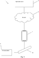
- Fig. 1 shows an example system 1 for managing a smoking substitute device 10.
- the system 1 as shown in Fig. 1 includes a mobile device 2, an application server 4, an optional charging station 6, as well as the smoking substitute device 10.
- the smoking substitute device 10 is configured to communicate wirelessly, e.g. via BluetoothTM, with an application (or "app") installed on the mobile device 2, e.g. via a suitable wireless interface (not shown) on the mobile device 2.
- the mobile device 2 may be a mobile phone, for example.
- the application on the mobile phone is configured to communicate with the application server 4, via a network 8.
- the application server 4 may utilise cloud storage, for example.
- the network 8 may include a cellular network and/or the internet.
- the mobile device 2 may be configured to communicate via the network 8 according to various communication channels, preferably a wireless communication channel such as via a cellular network (e.g. according to a standard protocol, such as 3G or 4G) or via a WiFi network.
- a wireless communication channel such as via a cellular network (e.g. according to a standard protocol, such as 3G or 4G) or via a WiFi network.
- the app installed on the mobile device and the application server 4 may be configured to assist a user with their smoking substitute device 10, based on information communicated between the smoking substitute device 10 and the app and/or information communicated between the app and the application server 4.
- the charging station 6 may be configured to charge (and optionally communicate with) the smoking substitute device 10, via a charging port on the smoking substitute device 10.
- the charging port on the smoking substitute device 10 may be a USB port, for example, which may allow the smoking substitute device to be charged by any USB-compatible device capable of delivering power to the smoking substitute device 10 via a suitable USB cable (in this case the USB-compatible device would be acting as the charging station 6).
- the charging station could be a docking station specifically configured to dock with the smoking substitute device 10 and charge the smoking substitute device 10 via the charging port on the smoking substitute device 10.
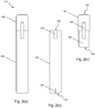
- Fig. 2(a) shows an example smoking substitute device 110 for use as the smoking substitute device 10 in the system 1 of Fig. 1 .
- the smoking substitute device 110 includes a main body 120 and a consumable 150.
- the consumable 150 may alternatively be referred to as a "pod".
- the smoking substitute device 110 is a closed system vaping device, wherein the consumable 150 includes a sealed tank 156 and is intended for one-use only.
- Fig. 2(a) shows the smoking substitute device 110 with the main body 120 physically coupled to the consumable 150.
- Fig. 2(b) shows the main body 120 of the smoking substitute device 110 without the consumable 150.
- Fig. 2(c) shows the consumable 150 of the smoking substitute device 110 without the main body 120.
- the main body 120 and the consumable 150 are configured to be physically coupled together, in this example by pushing the consumable 150 into a coupling portion of the main body 120.
- the coupling portion may comprise an aperture in a top end 122 of the main body 120, e.g. with the consumable 150 being retained in the aperture via an interference fit.
- the main body 120 and the consumable could be physically coupled together by screwing one onto the other, through a bayonet fitting, or through a snap engagement mechanism, for example.
- An optional light 126 e.g. an LED located behind a small translucent cover, is located a bottom end 124 of the main body 120. The light 126 may be configured to illuminate when the smoking substitute device 110 is activated.
- the consumable 150 includes a mouthpiece (not shown) at a top end 152 of the consumable 150, as well as one or more air inlets (not shown in Fig. 2 ) so that air can be drawn into the smoking substitute device 110 when a user inhales through the mouthpiece.
- a tank 156 that contains e-liquid.
- the tank 156 may be a translucent body, for example.
- the tank 156 preferably includes a window 158, so that the amount of e-liquid in the tank 156 can be visually assessed.
- the main body 120 includes a slot 128 so that the window 158 of the consumable 150 can be seen whilst the rest of the tank 156 is obscured from view when the consumable 150 is inserted into the aperture in the top end 122 of the main body 120.
- the consumable 150 is a "single-use" consumable. That is, upon exhausting the e-liquid in the tank 156, the intention is that the user disposes of the whole consumable 150.
- the e-liquid i.e. aerosol former
- the tank 156 may be refillable with e-liquid or the e-liquid may be stored in a non-consumable component of the system.
- the e-liquid may be stored in a tank located in the device or stored in another component that is itself not single-use (e.g. a refillable tank).
- the tank 156 may be referred to as a "clearomizer” if it includes a window 158, or a “cartomizer” if it does not.
- Fig. 3(a) is a schematic view of the main body 120 of the smoking substitute device 110.
- Fig. 3(b) is a schematic view of the consumable 150 of the smoking substitute device 110.
- the main body 120 includes a power source 128, a control unit 130, an airflow sensor 131, a memory 132, a wireless interface 134, an electrical interface 136, and, optionally, an accelerometer 135 and/or one or more additional components 138.
- the main body 120 includes one or more auxiliary components, i.e. components that are not essential to the provision of a smoking substitute function. Examples of an auxiliary component include the wireless interface 134, the optional accelerometer 135 or any of the optional additional components, which are discussed below.
- the power source 128 is preferably a battery, more preferably a rechargeable battery.
- a charging port 139 may be provided for connecting the rechargeable battery to an external power source.
- the control unit 130 may include a microprocessor, for example.
- the memory 132 is preferably includes non-volatile memory.
- the wireless interface 134 is preferably configured to communicate wirelessly with the mobile device 2, e.g. via Bluetooth.
- the wireless interface 134 could include a BluetoothTM antenna.
- the accelerometer 135 may function as a motion sensor to receive inputs for controlling the device.
- the main body 120 comprises a coupling portion 121 that includes the electrical interface 136.
- the electrical interface 136 may include one or more electrical contacts.
- the electrical interface 136 may be located in, and preferably at the bottom of, the aperture in the top end 122 of the main body 120.
- the electrical interface 136 may be configured to pass electrical power from the power source 128 to (e.g. a heating device of) the consumable 150 when the smoking substitute device 110 is activated, e.g. via the electrical interface 160 of the consumable 150 (discussed below).
- the electrical interface may be configured to receive power from the charging station 6 when the main body 120 is not physically coupled to the consumable 150.
- the additional components 138 of the main body 120 may include the optional light 126 discussed above.
- the additional components 138 of the main body 120 may, if the power source 128 is a rechargeable battery, include a charging port configured to receive power from the charging station 6. This may be located at the bottom end 124 of the main body 120. Alternatively, the electrical interface 136 discussed above is configured to act as a charging port configured to receive power from the charging station 6 such that a separate charging port is not required.
- the additional components 138 of the main body 120 may, if the power source 128 is a rechargeable battery, include a battery charging control circuit, for controlling the charging of the rechargeable battery.
- a battery charging control circuit could equally be located in the charging station 6 (if present).
- the airflow sensor 131 is configured to detecting airflow in the smoking substitute device 110, e.g. caused by a user inhaling through a mouthpiece 166 (discussed below) of the smoking substitute device 110.
- the smoking substitute device 110 may be configured to be activated when airflow is detected by the airflow sensor.
- the additional components 138 of the main body 120 may include an actuator, e.g. a button.
- the smoking substitute device 110 may be configured to be activated when the actuator is actuated. This provides an alternative to the airflow sensor noted, as a mechanism for activating the smoking substitute device 110.
- the additional components 138 of the main body 120 may include a reader configured to read information associated with the consumable from a machine readable data source included in (e.g. contained in the body of, or attached to) the consumable 150.
- the reader may be configured to read information from the machine readable data source wirelessly, e.g. via electromagnetic waves or optically.
- the machine readable data source included in the consumable 150 could be an RFID tag (in which case the reader included in the main body 120 may be an RFID reader) or a visual data source such as a barcode (in which case the reader included in the main body may be an optical reader, e.g. a barcode scanner).
- Various wireless technologies and protocols may be employed to allow the reader to wirelessly read information from a machine readable data source included in or attached to the consumable 150, e.g. NFC, Bluetooth, Wi-Fi, as would be appreciated by a skilled person.
- the reader may be configured to read information from the machine readable data source non-wirelessly, e.g. using a direct electrical connection between the main body 120 and consumable 150.
- the consumable 150 includes the tank 156, an electrical interface 160, a heating device 162, one or more air inlets 164, a mouthpiece 166, and, optionally, one or more additional components 168.
- the electrical interface 160 of the consumable 150 may include one or more electrical contacts.
- the electrical interface 136 of the main body 120 and an electrical interface 160 of the consumable 150 are preferably configured to contact each other and therefore electrically couple the main body 120 to the consumable 150 when the main body 120 is physically coupled to the consumable 150. In this way, electrical energy (e.g. in the form of an electrical current) is able to be supplied from the power source 128 in the main body 120 to the heating device 162 in the consumable 150.
- the heating device 162 is preferably configured to heat e-liquid contained in the tank 156, e.g. using electrical energy supplied from the power source 128.
- the heating device 162 may include a heating filament and a wick, wherein a first portion of the wick extends into the tank 156 in order to draw e-liquid out from the tank 156, and wherein the heating filament coils around a second portion of the wick located outside the tank 156.
- the heating filament is configured to heat up e-liquid drawn out of the tank 156 by the wick to produce an aerosol vapour.
- the one or more air inlets 164 are preferably configured to allow air to be drawn into the smoking substitute device 110, when a user inhales through the mouthpiece 166.
- the additional components 168 of the consumable 150 may include a machine readable data source, which may e.g. be contained in the body of, or attached to the consumable 150.
- the machine readable data source may store information associated with the consumable.
- the information associated with the consumable may include information concerning the content of the consumable (e.g. e-liquid type, batch number) and/or a unique identifier, for example.
- the machine readable data source may be rewritable, e.g. a rewritable RFID chip, or read only, e.g. a visual data source such as a barcode.
- the additional components 138 of the main body 120 may include a reader configured to read information associated with the consumable from the machine readable data source.
- a user activates the smoking substitute device 110, e.g. through actuating an actuator included in the main body 120 or by inhaling through the mouthpiece 166 as described above.
- the control unit 130 may supply electrical energy from the power source 128 to the heating device 162 (via electrical interfaces 136, 166), which may cause the heating device 162 to heat e-liquid drawn from the tank 156 to produce a vapour which is inhaled by a user through the mouthpiece 166.
- smoking substitute device 110 shown in Figs. 2 and 3 shows just one example implementation of a smoking substitute device, and that other forms of smoking substitute device could be used as the smoking substitute device 10 of Fig. 1 .
- a HNB smoking substitute device including a main body and a consumable could be used as the smoking substitute device 10 of Fig. 1 , instead of the smoking substitute device 110.
- One such HNB smoking substitute device is the IQOSTM smoking substitute device discussed above.
- Embodiments of the present invention relate to the transition of a smoking substitute device of the type discussed above from a shipping mode to an active mode, upon detection of a predetermined set of conditions being fulfilled.
- the predetermined set of conditions should comprise the positive detection of at least two things - for example, an inhalation event detected by airflow sensor 131 in addition to the presence of a consumable 150 received in the main body 120.
- the main body may be configured to detect when the electrical interface 136 within the main body is electrically coupled with a compatible electrical interface 160 of a consumable 150.
- the detection functionality may be provided by a suitable detection unit, e.g. sensor, that is sensitive to an electrical property at the electrical interface 136.
- the detection unit may be a self-contained part of the coupling portion 121, or may be configured to send a signal indicative of the electrical property to the control unit 130.
- the detection unit may comprise circuitry configured to communicate electrical signals to the control unit 130, in order to detect a change in any of current, voltage or resistance at the electrical interface 136.
- the control unit 130 may be configured to determine, based on a signal from the detection unit, whether or not a consumable 150 is received in the coupling portion 121.
- control unit 130 may be configured to detect a resistance at the electrical interface 136.
- the resistance may vary depending on whether or not a predetermined type or size or configuration of electrical component, such as a resistance coil, is present (i.e. connected) to the electrical interface 136.
- the airflow sensor 131 is configured for detecting an airflow in the main body 120, e.g. caused by a user inhaling through a mouthpiece (which may be comprised within a consumable).
- a mouthpiece which may be comprised within a consumable.
- the main body 120 When operating in an active mode, the main body 120 is configured to transfer power through the electrical interface when an airflow is detected by the airflow sensor 131.
- the airflow sensor 131 may be configured to transmit a detection signal to the control unit, when it detects airflow in the airflow channel.
- the control unit 130 can then use that detection signal, either in isolation or in combination with other signals or other factors, to control operation of the main body 120.
- the control unit 130 may be associate each inhalation event detected by the airflow sensor with a time information.
- the time information may include a time stamp that indicates when the airflow was initially detected, and/or a time period throughout which an airflow was detected.
- the main body 120 When operating in an active mode, the main body 120 is configured to supply power to the consumable 150, in order to activate the heating device 162 to heat the liquid and/or tobacco within the consumable 150, when an inhale action is detected.
- the control unit 130 may send control instructions to the electrical interface 136, via suitable control circuitry, to instruct it to supply power, from the power source 128, to the electrical interface 160 of the consumable 150, during an inhale action, upon receipt of positive airflow detection signals form the airflow sensor 131.
- the control instruction from the control unit 130 that power is to be supplied to the consumable 150 initiates the switching on of an electrical switch (not shown) which completes an electrical circuit between the power source 128 and the consumable 160, via the two coupled electrical interfaces 136, 160.
- control unit 130 may permit the switch to be in an ON state, and therefore the heating device 160 to be activated for heating the tobacco and/or liquid, for a short, predetermined period, for example 3 seconds, each time an inhale action is detected.
- the switched is switched off again, breaking the electrical circuit between the power source 128 and the consumable 160, via the two coupled electrical interfaces 136, 160.
- the microprocessor may allow the switch to be switched on, and the heating device to be activated, for a different predetermined length of time and/or it may be configured to allow the heating device to be activated for the duration of each inhale, and optionally for a short time interval, after each inhale has ended.
- the main body may include one or more auxiliary components. Two auxiliary components are discussed below.
- the first is wireless interface 134, which may be a BluetoothTM interface configured to wirelessly communicate with a BluetoothTM interface of another device (not shown), such as a mobile device (e.g. smartphone).
- the BluetoothTM interface can be configured to form a paired or bonded wireless communication link with the mobile device. It can further be configured to transmit data to the other device, and/or to an application running on the other device.
- the transmitted data may comprise telemetry data, which concerns the wireless communication link itself and activity/operation of the wireless communication link.
- the transmitted data may also comprise operational data for the smoking substitute device, for example voltage level readouts from the power source 128, which are indicative of remaining battery power or for example position and/or orientation data from the accelerometer (discussed further below), which are indicative of movements or physical actions made using the smoking substitute device.
- the mobile device and/or the application may be configured to monitor received data from the smoking substitute device and to make calculations or determinations using the received data, and to transmit control signals or notifications to the smoking substitute device, based on the received data.
- an application may be configured to send the smoking substitute device a notification when it is at low battery level, and possibly to send instructions regarding how various components within the smoking substitute device should be controlled at low battery level.
- the other auxiliary component in the smoking substitute device is an accelerometer 135.
- An accelerometer is, as the skilled reader will know, an electromechanical device that measures acceleration forces, and provides a measure of "proper acceleration", which is the acceleration of a body or object, relative to free fall.
- the accelerometer 135 in this embodiment, comprised within the smoking substitute device, is configured to measure dynamic acceleration forces, and so can sense movement or vibrations.
- the accelerometer 135 is configured to measure acceleration and its outputs may be used to determine position factors and/or orientation factors such as tilt, tilt angle, and incline, as well as being used to determine actions or events such as rotation, vibration and collision.
- the accelerometer 135 may be a piezoelectric accelerometer. However other types of accelerometer may be used in a smoking substitute device, such as a capacitance accelerometer.
- the accelerometer 135 may comprise a three-axis model, to enable it to sense rotational tilt, as well as movement in a two-dimensional plane.
- the accelerometer 135 may be configured to detect movement and collisions, and to provide one or more voltage outputs to the control unit 130, as a result of what it has detected.
- the accelerometer 135 can, for example, detect the action of the smoking substitute device being tapped against (i.e. relatively gently colliding with) a surface. When the user taps the device, the accelerometer 135 transmits a corresponding voltage signal to the control unit 130.
- the control unit 130 can then control the memory 132 to store (at least temporarily) a measure of the voltage signal, along with an indicator of the time at which it was received.
- the smoking substitute device may also submit a signal to the mobile device, via the wireless communication link that has been established between them, regarding the detection that the accelerometer 135 has made.
- This can be very useful as the smoking substitute device may be preconfigured for a tap (or a plurality of taps) to form part of a sequence for the user to convey instructions to the device and/or to the connected mobile device or application.
- operation of the accelerometer 135 can prove very useful to a user, even when he or she is not actively using the smoking substitute device for smoking substitute action.
- the present inventors have recognised that it is desirable to control and manage the power supply to auxiliary components within a smoking substitute device, and that is may be particularly useful to manage this control independently of the power supply control to the consumable during normal operation.
- Embodiments of the invention provide a device and method for controlling the power supply to the auxiliary components of a smoking substitute device, in a reliable and user-controllable manner.
- the auxiliary components comprise an accelerometer 135 and a BluetoothTM interface 134.
- other embodiments may comprise other auxiliary components instead of or as well as these ones.
- the auxiliary components are both treated the same, by the control method.
- individual auxiliary components, or selected ones or small groups amongst a plurality of auxiliary components may have their own respective control rules applied thereto.
- the smoking substitute device, and the components housed within its main body 120, may be selectively operable in a shipping mode and in an active mode.
- the shipping mode and the active mode may be mutually exclusive, i.e. the smoking substitute device cannot simultaneously be running in both shipping mode and active mode.
- the power source 128 When the device is in the active mode, the power source 128 is configured to supply power to the auxiliary components. Therefore, the auxiliary components operate normally when the device is in the active mode.
- the active mode may comprise a plurality of sub-modes. The sub-modes may permit selective activation of auxiliary components, as discussed in more detail below.
- the power source 128 is restricted from supplying power to the auxiliary components.
- the smoking substitute device in this particular embodiment may thus be configured to entirely prevent power from being supplied to the auxiliary components when the smoking substitute device is in the shipping mode. Therefore, when the smoking substitute device is in shipping mode, the wireless interface 134 and the accelerometer 135 will not operate as there will be no power supplied to them.
- a smoking substitute device may be configured to restrict but not entirely prevent the power supply to the auxiliary components when in shipping mode.
- the power source 128 may also be prevented from supplying power to the electrical interface 136 within the coupling portion 121. Therefore, in this example of a shipping mode, the smoking substitute device cannot direct power to the heating device 162 of a consumable 160, even if the consumable 150 is received in the smoking substitute device. However, in other embodiments the supply of power to the electrical interface 136 within the coupling portion may not be prevented, although it may be restricted in some embodiments, when the smoking substitute device is in shipping mode.
- the smoking substitute device may be configured to enter shipping mode after first manufacture, assembly and testing, so that it is in shipping mode when it is packaged up and transported for distribution or sale, and when it is in a shop or other location, awaiting purchase by a user.
- the shipping mode is operationally efficient and ensures that minimal power is consumed by the device between manufacture and assembly and unpacking by the user. It also provides a safety feature, for example by preventing overheating of the smoking substitute device, which might otherwise occur if it had several electrical components operating within a confined package, before purchase.
- a smoking substitute device may have to be operated, at least briefly, in an active mode or in a mode that simulates an active mode, for it to be properly tested before it enters shipping mode for transportation.
- a smoking substitute device may be pre-configured, during the manufacture process, to have a separate "initial testing" mode (in addition to the active mode and shipping mode), which allows the components to be at least briefly activated for testing.
- the product manufacturer or tester can activate the initial testing mode for testing and provide a pre-determined instruction or set of conditions, in order for the device to then transition to shipping mode, after testing.
- the smoking substitute device does not have a separate initial testing mode but it is pre-configured so that the manufacturer or tester can briefly operate the device in an active mode, or in a mode that simulates an active mode, for testing.
- the smoking substitute device will then transition to shipping mode for transportation, if there is no airflow detected for a predetermined period of time.
- the device may automatically transition to the shipping mode, once the predetermined period of time has passed, after testing is complete.
- the predetermined period of time applied in this situation, for transitioning the device to shipping mode after testing, can be relatively brief.
- the transition from the initial testing mode to shipping mode may also have a requirement that the smoking substitute device should not have a consumable received in the coupling portion. It is known that smoking substitute devices are typically not packaged or sold with consumables received therein. Consumables and smoking substitute devices are typically sold separately.
- the smoking substitute device is configured so that the user must ensure that two conditions are met, in order to transition the smoking substitute device from the shipping mode to the active mode.
- the two conditions are:
- the user in order to transition the smoking substitute device from the shipping mode to the active mode, is to correctly insert a suitable consumable 150 into the smoking substitute device, so that it couples mechanically and electrically with the coupling portion 121, and to perform an inhalation through the smoking substitute device, via the mouthpiece 166 of the inserted consumable 150. Therefore, advantageously, the user can switch the smoking substitute device to the active mode - which means that power will be supplied to is auxiliary components - without requiring the actuation of (or even the presence in the device of) a separate dedicated user input component, for example an on/off button or switch.
- the smoking substitute device 162 of the consumable 150 following the steps to transition the smoking substitute device to operating in the active mode will also enable the supply of power to the heating device 162 of the consumable 150, via the coupled electrical interfaces 136, 160 of the smoking substitute device and of the consumable 150.
- a separate routine may be required in order to initiate the supply of power to the heating device 162 of the consumable 150, for the first time.
- the subsequent operation of the heating device 162 when the smoking substitute device is in the active mode can be controlled as described in detail above, based on detection signals issued by the airflow sensor 131, when a user inhales through the smoking substitute device.
- the method for controlling the operation of the heating device 162 when the smoking substitute device is in the active mode is further refined, because the active mode has two sub-modes.
- Other embodiments may not have any sub-modes, and still others may have more than two sub-modes.
- Other embodiments may also have sub-modes within the shipping mode, but this particular embodiment does not.
- the first sub-mode may be referred to as a so-called "use mode". It is a sub-mode of the active mode in which the control unit 130 of the smoking substitute device permits power to be supplied to the consumable 150. Notably, if the smoking substitute device is in "use mode", power can be supplied to the heating device 162 in the consumable 150, to enable liquid or tobacco to be heated for smoking substitute action. Power need not be continually supplied to the heating device 162 when the smoking substitute device is in the use mode. Instead, the times at which power will be supplied to the heating device 162 will still be controlled according to the detection signals received from the airflow sensor 131, indicating user inhale actions.
- the smoking substitute device will default to being in the use mode (or sub-mode) when the device transitions from operating in a shipping mode to operating in an active mode, unless certain pre-set operating conditions determine that it cannot be in use mode. This will be understood further from the description of the second sub-mode, below.
- the second sub-mode of the active mode which may be referred to as a so-called "standby mode" is a sub-mode in which power is supplied to the auxiliary components, but not to the consumable 150.
- the smoking substitute device therefore does not enable liquid or tobacco in the consumable 150 to be heated for smoking substitute action, when it is in standby mode.
- the smoking substitute device will only enter standby mode if, when the device transitions from operating in a shipping mode to operating in an active mode, there is insufficient power (i.e. insufficient battery level) to operate both the auxiliary components and the heating device 162 within the consumable 150.
- the standby mode therefore enables the auxiliary components to continue to operate, and carry out their important functions as detailed above, but prevents smoking substitute action.
- the smoking substitute device During subsequent operation of the smoking substitute device, once it has sufficient power (and if the conditions for transitioning back to shipping mode, as detailed below, have not been met) the smoking substitute device will default to being in active mode, in which supplying power to the heating device is permissible, in accordance with the control signals based on the detected airflows within the smoking substitute device.
- the "use” sub-mode refers to the operating mode of the smoking substitute device when it is actively supplying power to the heating device for smoking substitute action. Therefore, the device would be operating in “use mode” when the user is inhaling on the smoking substitute device.
- the "standby” sub-mode refers to the operating mode of the smoking substitute device when it has transitioned out of shipping mode, but it is not currently actively supplying power to the heating device for smoking substitute action. Therefore, the device would be operating in "standby mode” in between inhalation actions, if the conditions are not met for it to transition back to shipping mode.
- a smoking substitute device may not be possible for a smoking substitute device to automatically transition back to being in shipping mode. It may instead require a dedicated user input, either directly made at the smoking substitute device or made via a connected mobile device or application.
- the smoking substitute device is configured so that it can transition back to shipping mode automatically, if certain conditions are met.
- the smoking substitute device is configured to transition back to operating in shipping mode if no further inhale actions are detected during a pre-determined period of time following the most recent inhale action.
- That pre-determined period of time may be relatively long. For example, it may be of the order of a few days or even a few weeks.
- the transition can be controlled by the control unit, which is configured to make determinations based on signals received from the air flow sensor and the electrical interface within the coupling portion, and to issue control instructions accordingly.
- the present inventor(s) recognise that it is likely to be inconvenient to the user if the smoking substitute device transitions back to shipping mode too readily, because operation of the auxiliary components that the user finds useful is disabled when the device is in shipping mode.
- the present inventors have further recognised that this potential inconvenience should be balanced against the inconvenience and inefficiency disadvantages of continually operating the auxiliary components if the smoking substitute device is going unused by the user for smoking substitute action for extended periods of time.
- the length of the pre-determined period of time, after which the smoking substitute device will transition back to being in shipping mode if no inhale actions are detected will be different dependent on whether or not the device has a consumable inserted therein. If the smoking substitute device has a consumable inserted therein, which is detectable via the electrical interfaces of the smoking substitute device and consumable as detailed above, the control unit in this refinement of the present embodiment may be configured to interpret the presence of that consumable as an indication that the user is likely to want to use the device for smoking substitute action again in the short to medium term. The microprocessor will therefore be configured only to transition the device back to shipping mode if no inhalation actions are detected for a relatively long first period of time.
- the microprocessor will be configured to interpret this as an indication that the user may not want to use the device for smoking substitute action again in the short to medium term and therefore it will be configured to transition the device back to shipping mode if no inhalation actions are detected for second period of time, that is shorter than the aforementioned first period of time.
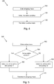
- Fig. 4 is a flow diagram for a method 400 of controlling the operating mode of a smoking substitute device according to an embodiment of the invention. This method 400 concerns the transition from the shipping mode to the active mode.
- the method 400 begins with a step 402 of entering the shipping mode, e.g. after manufacture before transportation to a sale port, or upon detecting a certain period of inactivity.
- the method continues with a step 404 of detecting a transition condition.
- the transition condition preferably has two or more criteria, such as detection of airflow through the device and detection of a connected consumable.
- the detection of the transition condition may be performed by the control unit of the smoking substitute device, e.g. based on signals from components therein that are active in the shipping mode.
- the method continues with a step 406 of transitioning to the active mode if the transition condition is fulfilled.
- Fig. 5 is a flow diagram of a method 500 of controlling the operating mode of a smoking substitute device according to an embodiment of the invention. This method 500 concerns the transition from the active mode to the shipping mode.
- the method 500 begins with a step 502 of entering the active mode, e.g. after the method 400 of Fig. 4 is performed.
- the method continues with a step 504 of detecting whether or not a consumable is present.
- This step may be performed by the control unit 130 detecting an electrical property (e.g. resistance) at the electrical interface 136, as discussed above.
- an electrical property e.g. resistance
- step 506 of detecting no airflow through the main body within a first time period t1. This step 506 may be performed by the control unit 130 monitoring an output from the airflow sensor 131. If no airflow is detected through the main body within the first time period t1, the method continues with a step 510 of transitioning to the shipping mode.
- the method continues with a step 508 of detecting no airflow through the main body within a second time period t2.
- the second time period t2 is preferably shorter than the first time period t1.
- This step 508 may be performed by the control unit 130 monitoring an output from the airflow sensor 131. If no airflow is detected through the main body within the second time period t2, the method continues with a step 510 of transitioning to the shipping mode.
- the above disclosure presents an intelligent and sophisticated method and device for controlling operational modes of a smoking substitute device.
- the approach described herein ensures enhance efficiency and safety of the device at times when operation of certain of its components is not required, and intuitive and straight forward activation of operation of auxiliary components at time when they are likely to be required and appreciated by the user.
- shipment mode "active mode”, “use mode” and “standby mode” are intended to be illustrative only and are not intended to be limiting. Other terms may be used instead, to describe the respective operational states of a smoking substitute device, as detailed above.
Priority Applications (4)
| Application Number | Priority Date | Filing Date | Title |
|---|---|---|---|
| EP19179932.9A EP3750426A1 (fr) | 2019-06-13 | 2019-06-13 | Système et procédé de gestion d'un dispositif de substitution du tabac |
| PCT/EP2020/066388 WO2020249789A1 (fr) | 2019-06-13 | 2020-06-12 | Dispositifs substituts d'usage de tabac et procédés, systèmes et appareils associés |
| EP20731151.5A EP3982776A1 (fr) | 2019-06-13 | 2020-06-12 | Dispositifs substituts d'usage de tabac et procédés, systèmes et appareils associés |
| US17/549,436 US20220095688A1 (en) | 2019-06-13 | 2021-12-13 | Smoking substitute devices and associated methods, systems and apparatuses |
Applications Claiming Priority (1)
| Application Number | Priority Date | Filing Date | Title |
|---|---|---|---|
| EP19179932.9A EP3750426A1 (fr) | 2019-06-13 | 2019-06-13 | Système et procédé de gestion d'un dispositif de substitution du tabac |
Publications (1)
| Publication Number | Publication Date |
|---|---|
| EP3750426A1 true EP3750426A1 (fr) | 2020-12-16 |
Family
ID=66857751
Family Applications (1)
| Application Number | Title | Priority Date | Filing Date |
|---|---|---|---|
| EP19179932.9A Ceased EP3750426A1 (fr) | 2019-06-13 | 2019-06-13 | Système et procédé de gestion d'un dispositif de substitution du tabac |
Country Status (1)
| Country | Link |
|---|---|
| EP (1) | EP3750426A1 (fr) |
Citations (6)
| Publication number | Priority date | Publication date | Assignee | Title |
|---|---|---|---|---|
| WO2013138384A2 (fr) * | 2012-03-12 | 2013-09-19 | Uptoke Llc | Dispositif de vaporisation électronique et procédés d'utilisation |
| WO2014144678A2 (fr) * | 2013-03-15 | 2014-09-18 | Lewis Michael W | Dispositif à fumer électronique, systèmes et procédés associés |
| EP3054798A2 (fr) * | 2013-10-09 | 2016-08-17 | Nicoventures Holdings Limited | Système de distribution de vapeur électronique |
| US20170013879A1 (en) * | 2015-07-17 | 2017-01-19 | R. J. Reynolds Tobacco Company | Load-based detection of an aerosol delivery device in an assembled arrangement |
| EP3155907A1 (fr) * | 2015-10-15 | 2017-04-19 | Fontem Holdings 1 B.V. | Cigarette électronique avec réservoir de liquide multicaméral |
| US20180184711A1 (en) * | 2015-07-01 | 2018-07-05 | c/o Nicoventures Holdings Limited | Electronic aerosol provision system |
-
2019
- 2019-06-13 EP EP19179932.9A patent/EP3750426A1/fr not_active Ceased
Patent Citations (6)
| Publication number | Priority date | Publication date | Assignee | Title |
|---|---|---|---|---|
| WO2013138384A2 (fr) * | 2012-03-12 | 2013-09-19 | Uptoke Llc | Dispositif de vaporisation électronique et procédés d'utilisation |
| WO2014144678A2 (fr) * | 2013-03-15 | 2014-09-18 | Lewis Michael W | Dispositif à fumer électronique, systèmes et procédés associés |
| EP3054798A2 (fr) * | 2013-10-09 | 2016-08-17 | Nicoventures Holdings Limited | Système de distribution de vapeur électronique |
| US20180184711A1 (en) * | 2015-07-01 | 2018-07-05 | c/o Nicoventures Holdings Limited | Electronic aerosol provision system |
| US20170013879A1 (en) * | 2015-07-17 | 2017-01-19 | R. J. Reynolds Tobacco Company | Load-based detection of an aerosol delivery device in an assembled arrangement |
| EP3155907A1 (fr) * | 2015-10-15 | 2017-04-19 | Fontem Holdings 1 B.V. | Cigarette électronique avec réservoir de liquide multicaméral |
Similar Documents
| Publication | Publication Date | Title |
|---|---|---|
| JP7157848B2 (ja) | エアロゾル生成装置及びその制御方法 | |
| US20210045453A1 (en) | Systems for managing smoking substitute devices and associated methods | |
| US20220095688A1 (en) | Smoking substitute devices and associated methods, systems and apparatuses | |
| KR102141648B1 (ko) | 에어로졸 생성 장치 및 그 제어 방법 | |
| RU2710771C2 (ru) | Пользовательский интерфейс для устройства доставки аэрозоля | |
| US20210068466A1 (en) | Smoking substitute device | |
| KR102099929B1 (ko) | 에어로졸 생성 장치 및 그 제어 방법 | |
| EP3759898A1 (fr) | Appareil et procédé de surveillance d'état de batterie dans un dispositif de substitution pour fumeurs avec fonctionnalité de réseau | |
| EP3759899B1 (fr) | Appareil et procédé de surveillance de localisation d'un dispositif de substitution à fumer activé par réseau | |
| US20210068468A1 (en) | Systems for managing smoking substitute devices and associated methods | |
| US20210037891A1 (en) | Smoking substitute device | |
| EP3838030A1 (fr) | Système et procédé de gestion d'un dispositif de substitution du tabac | |
| EP3838024A1 (fr) | Système et procédé de gestion d'un dispositif de substitution du tabac | |
| US20210378312A1 (en) | Smoking substitute device | |
| EP3750426A1 (fr) | Système et procédé de gestion d'un dispositif de substitution du tabac | |
| EP3750424A1 (fr) | Système et procédé de gestion d'un dispositif de substitution du tabac | |
| EP3927201A1 (fr) | Dispositif de substitution au tabagisme | |
| EP3869427A1 (fr) | Dispositif de substitution du tabac | |
| EP3750422A1 (fr) | Appareil et procédé de surveillance de batterie et dispositif de commande dans un dispositif de substitution du tabac | |
| EP3838006A1 (fr) | Dispositif de substitution du tabac et procédé de gestion d'un dispositif de substitution du tabac | |
| EP3838031A1 (fr) | Système de substitution du tabac et procédé de synchronisation d'au moins deux dispositifs de substitution du tabac | |
| US11771141B2 (en) | Smoking substitute device and system for managing a smoking substitute device | |
| EP3838022A1 (fr) | Système et procédé de gestion d'un dispositif de substitution du tabac | |
| EP3838029A1 (fr) | Dispositif et système de substitution du tabac | |
| EP3900553A1 (fr) | Procédé de fonctionnement d'un dispositif de génération d'aérosol |
Legal Events
| Date | Code | Title | Description |
|---|---|---|---|
| PUAI | Public reference made under article 153(3) epc to a published international application that has entered the european phase |
Free format text: ORIGINAL CODE: 0009012 |
|
| STAA | Information on the status of an ep patent application or granted ep patent |
Free format text: STATUS: THE APPLICATION HAS BEEN PUBLISHED |
|
| AK | Designated contracting states |
Kind code of ref document: A1 Designated state(s): AL AT BE BG CH CY CZ DE DK EE ES FI FR GB GR HR HU IE IS IT LI LT LU LV MC MK MT NL NO PL PT RO RS SE SI SK SM TR |
|
| AX | Request for extension of the european patent |
Extension state: BA ME |
|
| STAA | Information on the status of an ep patent application or granted ep patent |
Free format text: STATUS: THE APPLICATION HAS BEEN REFUSED |
|
| 18R | Application refused |
Effective date: 20210307 |