EP3750170B1 - Architecture de réacteur nucléaire intégré limitant les contraintes appliquées aux mécanismes intégrés - Google Patents
Architecture de réacteur nucléaire intégré limitant les contraintes appliquées aux mécanismes intégrés Download PDFInfo
- Publication number
- EP3750170B1 EP3750170B1 EP19704313.6A EP19704313A EP3750170B1 EP 3750170 B1 EP3750170 B1 EP 3750170B1 EP 19704313 A EP19704313 A EP 19704313A EP 3750170 B1 EP3750170 B1 EP 3750170B1
- Authority
- EP
- European Patent Office
- Prior art keywords
- driven member
- nuclear reactor
- control member
- central axis
- core
- Prior art date
- Legal status (The legal status is an assumption and is not a legal conclusion. Google has not performed a legal analysis and makes no representation as to the accuracy of the status listed.)
- Active
Links
- 230000007246 mechanism Effects 0.000 title claims description 55
- 230000005540 biological transmission Effects 0.000 claims description 34
- 239000007788 liquid Substances 0.000 claims description 29
- 238000001816 cooling Methods 0.000 claims description 12
- 239000012530 fluid Substances 0.000 claims description 12
- 239000003758 nuclear fuel Substances 0.000 claims description 12
- 230000000630 rising effect Effects 0.000 claims description 11
- 230000009257 reactivity Effects 0.000 claims description 9
- 230000000712 assembly Effects 0.000 description 6
- 238000000429 assembly Methods 0.000 description 6
- 230000005484 gravity Effects 0.000 description 6
- 238000006073 displacement reaction Methods 0.000 description 4
- 210000000056 organ Anatomy 0.000 description 4
- 230000004992 fission Effects 0.000 description 3
- IJGRMHOSHXDMSA-UHFFFAOYSA-N Atomic nitrogen Chemical compound N#N IJGRMHOSHXDMSA-UHFFFAOYSA-N 0.000 description 2
- 241000219504 Caryophyllales Species 0.000 description 2
- 230000003993 interaction Effects 0.000 description 2
- XLYOFNOQVPJJNP-UHFFFAOYSA-N water Substances O XLYOFNOQVPJJNP-UHFFFAOYSA-N 0.000 description 2
- 239000011358 absorbing material Substances 0.000 description 1
- 238000009835 boiling Methods 0.000 description 1
- 229910017052 cobalt Inorganic materials 0.000 description 1
- 239000010941 cobalt Substances 0.000 description 1
- GUTLYIVDDKVIGB-UHFFFAOYSA-N cobalt atom Chemical compound [Co] GUTLYIVDDKVIGB-UHFFFAOYSA-N 0.000 description 1
- 239000004020 conductor Substances 0.000 description 1
- 238000001514 detection method Methods 0.000 description 1
- 230000005611 electricity Effects 0.000 description 1
- 239000000446 fuel Substances 0.000 description 1
- 238000009434 installation Methods 0.000 description 1
- 229910052751 metal Inorganic materials 0.000 description 1
- 239000002184 metal Substances 0.000 description 1
- 150000002739 metals Chemical class 0.000 description 1
- 229910052757 nitrogen Inorganic materials 0.000 description 1
- 230000002285 radioactive effect Effects 0.000 description 1
Images

Classifications
-
- G—PHYSICS
- G21—NUCLEAR PHYSICS; NUCLEAR ENGINEERING
- G21C—NUCLEAR REACTORS
- G21C7/00—Control of nuclear reaction
- G21C7/06—Control of nuclear reaction by application of neutron-absorbing material, i.e. material with absorption cross-section very much in excess of reflection cross-section
- G21C7/08—Control of nuclear reaction by application of neutron-absorbing material, i.e. material with absorption cross-section very much in excess of reflection cross-section by displacement of solid control elements, e.g. control rods
- G21C7/12—Means for moving control elements to desired position
- G21C7/14—Mechanical drive arrangements
-
- G—PHYSICS
- G21—NUCLEAR PHYSICS; NUCLEAR ENGINEERING
- G21C—NUCLEAR REACTORS
- G21C1/00—Reactor types
- G21C1/32—Integral reactors, i.e. reactors wherein parts functionally associated with the reactor but not essential to the reaction, e.g. heat exchangers, are disposed inside the enclosure with the core
- G21C1/326—Integral reactors, i.e. reactors wherein parts functionally associated with the reactor but not essential to the reaction, e.g. heat exchangers, are disposed inside the enclosure with the core wherein the heat exchanger is disposed next to or beside the core
-
- G—PHYSICS
- G21—NUCLEAR PHYSICS; NUCLEAR ENGINEERING
- G21C—NUCLEAR REACTORS
- G21C15/00—Cooling arrangements within the pressure vessel containing the core; Selection of specific coolants
- G21C15/02—Arrangements or disposition of passages in which heat is transferred to the coolant; Coolant flow control devices
- G21C15/04—Arrangements or disposition of passages in which heat is transferred to the coolant; Coolant flow control devices from fissile or breeder material
- G21C15/06—Arrangements or disposition of passages in which heat is transferred to the coolant; Coolant flow control devices from fissile or breeder material in fuel elements
-
- Y—GENERAL TAGGING OF NEW TECHNOLOGICAL DEVELOPMENTS; GENERAL TAGGING OF CROSS-SECTIONAL TECHNOLOGIES SPANNING OVER SEVERAL SECTIONS OF THE IPC; TECHNICAL SUBJECTS COVERED BY FORMER USPC CROSS-REFERENCE ART COLLECTIONS [XRACs] AND DIGESTS
- Y02—TECHNOLOGIES OR APPLICATIONS FOR MITIGATION OR ADAPTATION AGAINST CLIMATE CHANGE
- Y02E—REDUCTION OF GREENHOUSE GAS [GHG] EMISSIONS, RELATED TO ENERGY GENERATION, TRANSMISSION OR DISTRIBUTION
- Y02E30/00—Energy generation of nuclear origin
- Y02E30/30—Nuclear fission reactors
Definitions
- the documents FR 3,039,695 and US 2015/0243377 A1 describe a nuclear reactor comprising a plurality of mechanisms for driving elements for controlling the reactivity of the heart. These mechanisms are fully housed in the tank. This makes it possible in particular to reduce the total height of the nuclear reactor.
- Each drive mechanism comprises in particular a motor entirely immersed in the primary liquid inside the tank.
- the primary liquid of the primary primary flow passes through the heart before interacting with certain submerged mechanisms, including the drive mechanisms of control organs.
- the primary flow has a very high flow rate for cooling the core.
- the drive mechanisms have mechanical play, in particular to allow the movement of the control members, so that a liquid at a very high flow rate is liable to damage the structure of the drive mechanisms.
- the motor is, for example, an electromotor comprising a not insignificant mass of metals which can be activated by irradiation, such as cobalt.
- An aim of the invention is therefore to provide a nuclear reactor having a reduced size and in which the interactions between the core and the submerged mechanisms are reduced.
- the object of the invention is a nuclear reactor of the aforementioned type in which the electric actuator is entirely immersed in the primary fluid, and in that the electric actuator is located outside the main primary flow.
- the nuclear reactor 10 shown in the figure 1 is an SMR type reactor (for Small and Medium Reactor, or small and medium reactor). This type of reactor equips for example small nuclear installations, with an output of a few hundred megawatts of electricity (MWe).
- This reactor is typically of the pressurized water type (PWR).
- PWR pressurized water
- BWR boiling water
- the reactor 10 comprises a vessel 12 having a central axis C, a plurality of nuclear fuel assemblies forming a core 14 arranged in the internal volume of the vessel 12, at least one control member 16 of the reactivity of the core 14 and minus a control member drive mechanism 18. More particularly, the reactor 10 comprises a plurality of control members 16 and a drive mechanism 18 per control member 16.
- each nuclear reactor has a large number of nuclear fuel assemblies and likewise a large number of control members and drive mechanisms.
- the central axis C is typically vertical or substantially vertical.
- the tank 12 is substantially of revolution around the central axis C.
- the terms lower and upper, top and bottom, top and bottom are understood relative to a vertical direction, corresponding substantially to the central axis C.
- the vessel 12 contains the primary liquid of the nuclear reactor.
- the reactor 10 also comprises a pressurizer 20 located in an upper part of the vessel 12 along the central axis C, the pressurizer 20 being in communication with the primary fluid in order to maintain the primary fluid at a given pressure.
- the pressurizer 20 extends over the entire upper part of the tank 12 from a certain height.
- the reactor 10 further comprises one or more steam generators 22 housed in the internal volume of the vessel 12 and extending around the control members 16 and the drive mechanisms 18.
- the steam generator (s) 22 present (s) a cylindrical symmetry around the central axis C.
- Nuclear fuel assemblies are elements elongated parallel to the central axis C, prismatic in shape, placed against each other.
- the control organs 16 of the reactivity of the heart are known as the control cluster or control bar. Each has a portion made of a neutron absorbing or neutron absorbing material. Each control member is of elongated shape parallel to the central axis C and of section adapted to allow inserting the control member into a channel, not shown, provided in the nuclear fuel assembly.
- Each control organ is aligned with the heart in a direction parallel to the central axis C.
- the drive mechanisms 18 are arranged in the internal volume of the tank. Each drive mechanism 18 is typically linked to one or more control members 16.
- the drive mechanisms 18 are also called CRDM from the acronym in English " Control Rod Drive Mechanism”.
- Each drive mechanism 18 is provided to move one of the control members 16 along an axis A parallel to the central axis C, so as to extract it entirely from the corresponding nuclear fuel assembly, or to insert it. over a determined length within the nuclear fuel assembly.
- each drive mechanism 18 comprises an electric actuator 18a and a transmission mechanism 18b.
- the electric actuator 18a comprises a motor 23 comprising a stator 24 and a rotor 25 capable of being driven in rotation.
- the electric actuator 18a is located under the pressurizer 20 in a direction parallel to the central axis C.
- the electric actuator 18a is completely immersed in the primary liquid inside the tank. More generally, the drive mechanisms 18 are completely immersed in the primary liquid inside the tank 12. None of the elements of the drive mechanisms 18 protrude outside the tank 12. In particular, the motor 23 , the driving device 26, the driven member 30 and the transmission member 34 are immersed in the primary liquid inside the tank 12. Typically, all of these elements are permanently immersed in the primary liquid.
- the reactor 10 has a reduced overall height.
- the stator 24 has a generally cylindrical shape around the axis A parallel to the central axis C.
- the rotor 25 is arranged inside the stator 24 and has a generally cylindrical shape coaxial with the axis A. It has a central passage 38 extending along the axis A.
- the driving device 26, besides the driving part 28, comprises a connecting part 40 engaged in the central passage 38, so that the rotor 25 and the connecting part 40 are integral in rotation, for example, by means of a connecting piece 41 extending between the rotor 25 and the connecting part 40.
- the driving device 26 comprises a rod 42 extending parallel to the central axis C along the axis A.
- the drive part 28 constitutes the lower section of said rod and the connecting part 40 the upper section of said rod.
- the drive part 28 is integral with the connecting part 40.
- the rod 42 is of large dimension along the axis A.
- the rod 42 extends downward along the axis A beyond the motor 23.
- the drive part 28 has a polygonal section, more particularly a square section, the section being taken perpendicular to the axis C.
- the driven member 30 extends around the axis A.
- the driven member 30 here has an overall tubular shape.
- the driven member 30 has, for example, a cylindrical outer shape of polygonal section, more particularly square. Outside the upper part, the driven member 30 has, for example, a cylindrical outer shape of circular section.
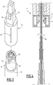
- the driven member 30 has an orifice 44 visible on the figure 3 extending along the axis A at least in an upper part of the driven member over a length greater than a maximum displacement of the control member 16, more particularly here over the entire height along the axis A of said driven member 30.
- the orifice 44 has a polygonal section corresponding to the polygonal section of the drive part 28.
- the upper part of the orifice 44 is, for example, defined in the upper part 43 of the driven member 30, so that at this level the driven member forms a ring of polyhedral shape.
- the orifice 44 has a circular section.
- the polygonal section of the drive part 28 is included in said circular section.
- the drive portion 28 extends into the orifice 44.
- the driven member 30 cooperates with the drive part 28 at the level of the upper part of the orifice 44, so that a rotation is transmitted between the drive part 28 and the driven member 30.
- a rotation of the rotor 25 is transmitted to the driven member 30 by the driving device 26.
- the driven member 30 has, moreover, a shoulder 46 on its outer surface, more particularly in its upper part.
- the driven member 30 also has a thread 48 on its outer surface, more particularly in a lower part.
- the driven member here comprises the screw.
- the driven member 30 has, moreover, at least one through hole 50 connecting the orifice 44 to the outer surface of the screw, more particularly above the thread 48.
- the through hole 50 allows in particular a liquid extending in the orifice 44 to be evacuated from the interior of the driven member 30, during rapid movements of the driven member 30 in the orifice 44.
- the transmission member 34 is linked to the control member 16. More particularly, the transmission member 34 is integral in translation along the axis A with the control member 16.
- the transmission member 34 cooperates with the driven member 30.
- the transmission member 34 here carries the nut.
- the nut cooperates with the driven member 30 at the level of the thread 48.
- the screw and the nut cooperate so that a rotation of the driven member 30 relative to the tank 12 results in a translation of the transmission member 34 along the axis A.
- a rotation of the drive part 28 of the driving device 26 relative to the stator 24 results in a translation of the control member 16 parallel to the central axis C.
- the transmission member 34 is locked in rotation around the axis A, so that a rotation of the driven member 30 around the axis A causes a translation of the transmission member 34 along the axis A by moving the nut on the thread 48.
- the drive mechanism comprises, for example, a sleeve surrounding the transmission member 34 and having a groove along the axis A, able to cooperate with a corresponding rib present in the transmission member 34.
- the cooperation between the groove and the rib prevents the rotation of the transmission member 34 but allows translation along the axis A, by displacement of the rib in the groove.
- the transmission member 34 has a groove along the axis A and the sleeve has the corresponding rib.
- a rotation of the driven member 30 in a first direction causes a descent of the transmission member along the axis A, while a rotation of the driven member 30 in a second direction opposite to the first direction causes a rise of the transmission member along axis A. More particularly, a rotation of the rotor 25 in the first direction causes a descent of the control member 16, while a rotation of the rotor in the second direction causes an ascent of l supervisory body 16.
- the electric actuator 18b of the drive mechanism 18 furthermore comprises a release system 52 of the control member 16 capable of releasing by gravity drop the control member 16 into the heart 14.
- the release system 52 makes it possible to pass the drive mechanism 18 from an armed position, in which the height of the control member 16 pressed into the heart 14 is controlled by rotation of the motor 23, to a released position, in which the control member 16 is driven into the heart 14 to a maximum height.
- the release of the control member 16 is obtained here by releasing the driven member 30, here causing the drop by gravity of the transmission member 34 and thus of the control member 16.
- the release is here controlled by a coil, the coil being supplied so as to keep the drive mechanism in the armed position during normal operation of the reactor.
- an interruption of the supply to the coil causes the gravity release and the passage from the armed position to the released position.
- the release system 52 comprises at least one element 54 movable between a holding position and a release position.
- the movable element 54 is held by the coil.
- the movable element 54 extends under the shoulder along the axis A so that the shoulder 46 rests on said movable element 54 and that the driven member 30 is maintained by the release system 52.
- the movable element 54 no longer extends under the shoulder along the central axis so as to release the driven member 30 which is driven by gravity drop along the axis. 'axis A, as visible on the figure 4 .
- the movable element 54 is, for example, one or more pawls.
- an impulse spring 55 accelerates the fall in the first moments.
- the fall time is particularly short. In fact, because the screw-nut connection is released with the driven member, the drop corresponds to a simple translational movement and not to the helical movement of a screw or a nut.
- the polyhedral shape of the drive part 28 in the cylindrical lower part of the orifice 44 of the driven member 30 is particularly advantageous because it limits the mechanical and / or hydraulic friction between the driven member 30 and the driving member. 26 during the gravity fall of the driven member 30, which makes it possible to reduce the fall time during the release.
- the arrangement of the driven member 30 around the driving member 26 is such that the driven member 30 is held around the leading member 26 after release, in particular thanks to the length of the driving member. 26. More particularly, the rod 42 extends far downward along the axis A so that the rod 42 remains engaged in the upper part of the driven member when the control member 16 is in the released position. .
- the raising of the driven member 30 is achieved by rotating the screw which then rises by cooperation with the nut.
- the movable element 54 is then moved into the holding position which makes it possible to return to the situation before release.
- the tank has a primary primary flow 56 of primary liquid visible on the figure 1 .
- the main primary flow 56 passes through the core 14 then rises in a direction parallel to the central axis C in a rising part 58 of the main primary flow 56 then goes down through the steam generator 22 in a falling part 60 of the main primary flow 56 .
- the fluid moves substantially parallel to the axis C.
- the rising part 58 corresponds, for example, to a part of the vessel partially comprising the driven member, the transmission member and / or the part of the control member not embedded in the nuclear fuel.
- the main primary flow 56 has a turning zone 62 between the rising part 58 and the descending part 60, the circulation of the fluid forming a cusp in the turning zone 62.
- the fluid moves substantially perpendicular to the central axis C so as to reach an inlet of a steam generator 22.
- the main primary flow 56 traverses in this order the rising part 58, the turning zone 62 then the descending part 60.
- the displacement of the primary liquid in the main primary flow 56 is here driven by at least one primary pump 57 located at the level of the descending part 60, for example, at the inlet and / or at the outlet of the steam generator.
- the electric actuator 18a is located outside the main primary flow 56.
- the main primary flow 56 does not pass through the electric actuator 18a including in particular the motor 23 of the drive mechanism 18.
- the electric actuator 18a is located above the turning zone 62 in the direction parallel to the central axis C.
- the electric actuator 18a has a height defined along the axis A located between the zone of reversal 62 and pressurizer 20.
- the electric actuator 18a does not interact directly with the fission products present in the main primary flow 56 at the outlet of the core 14 and is not subject to the constraints associated with the high flow and / or the high speed of the primary flow. main 56.
- the nuclear reactor 10 comprises a line 64 for cooling the motor 23 of the drive mechanism 18.
- the cooling line takes primary liquid from the main primary flow 56 at the outlet of the core 14 as shown or at the discharge of the primary pump (s) 57. .
- the travel time between the withdrawal of the primary liquid from the main primary flow 56 and the passage of the primary liquid at the level of the motor 23 is greater than a minimum time.
- the speed of the liquid is, for example, reduced compared to the speed in the main primary flow 56, in particular thanks to the use of diaphragm ( s).
- the minimum duration is greater than 50 seconds, preferably between 50 seconds and 150 seconds.
- short-lived elements are understood to mean elements having a half-life of less than 10 seconds, such as, for example, the 17 isotope of nitrogen ( 17 N) which has a half-life substantially equal to 4, 2s.
- the presence of a cooling line different from the main primary flow 56 makes it possible in particular to have a flow and / or a lower speed for the cooling of the drive mechanism compared to the flow and / or the speed for the cooling of the core. . This makes it possible to reduce the mechanical stresses due to the flow rate and / or the velocity of liquid applied to the drive mechanism.
- the flow rate required to refrigerate all of the electric actuators is 10,000 times less than the primary primary flow rate 56 required to refrigerate the heart.
- the cooling line is independent or corresponds to a withdrawal from the main primary flow 56 before passing through the core 14.
- the motor 23 is activated such that the rotor 25 is rotated in one direction.
- the rotational movement of the rotor is transmitted to the driving part 28 of the driving device 26, then to the driven device 30.
- the screw 32 is here driven in rotation, so that the nut 36 moves in translation along the screw. This causes the control member 16 to move in translation parallel to the central axis C.
- the release system 52 is activated so that the 'movable element 54 passes into the release position.
- the driven organ 30 is no longer held by the movable member 54 under the shoulder 46, so that the driven member 30 drops, causing the transmission member 34 and the control member 16.
- Such a nuclear reactor has a reduced height due to the drive mechanisms in the vessel and makes it possible to limit the interactions between the main primary flow and the motor of the drive mechanism, from a fission products point of view but also constraints. mechanics applied by the primary fluid.
- Such a drive mechanism has a reduced radial size.
- the architecture of the drive mechanism allows in particular that it is not necessary to provide an offset above the motor, unlike the mechanism. described in FR 3,039,695 in which the driving member protrudes from the motor.
- No element of the drive mechanism of the invention is here located at a height strictly greater than that of the motor along axis A.
- Such an architecture makes it possible in particular to use a motor of the wafer type, that is to say having a cylindrical shape without a central orifice, the motor extending above the rest of the drive mechanism.
- the diameter of the engine is, for example, substantially equal to that of the disc inscribed in the pitch of the fuel assemblies.
- Such a motor generally has a height less than that of a motor as described above. Thus, this makes it possible to further reduce the overall height of the drive mechanisms.
Landscapes
- Physics & Mathematics (AREA)
- Engineering & Computer Science (AREA)
- Plasma & Fusion (AREA)
- General Engineering & Computer Science (AREA)
- High Energy & Nuclear Physics (AREA)
- Chemical & Material Sciences (AREA)
- Chemical Kinetics & Catalysis (AREA)
- Monitoring And Testing Of Nuclear Reactors (AREA)
- Transmission Devices (AREA)
- Infusion, Injection, And Reservoir Apparatuses (AREA)
Priority Applications (1)
| Application Number | Priority Date | Filing Date | Title |
|---|---|---|---|
| PL19704313T PL3750170T3 (pl) | 2018-02-09 | 2019-02-08 | Zintegrowana architektura reaktora jądrowego ograniczająca obciążenia stosowane do mechanizmów zintegrowanych |
Applications Claiming Priority (2)
| Application Number | Priority Date | Filing Date | Title |
|---|---|---|---|
| FR1851115A FR3077919B1 (fr) | 2018-02-09 | 2018-02-09 | Architecture de reacteur nucleaire integre limitant les contraintes appliquees aux mecanismes integres |
| PCT/EP2019/053139 WO2019154988A1 (fr) | 2018-02-09 | 2019-02-08 | Architecture de réacteur nucléaire intégré limitant les contraintes appliquées aux mécanismes intégrés |
Publications (2)
| Publication Number | Publication Date |
|---|---|
| EP3750170A1 EP3750170A1 (fr) | 2020-12-16 |
| EP3750170B1 true EP3750170B1 (fr) | 2022-01-05 |
Family
ID=65363300
Family Applications (1)
| Application Number | Title | Priority Date | Filing Date |
|---|---|---|---|
| EP19704313.6A Active EP3750170B1 (fr) | 2018-02-09 | 2019-02-08 | Architecture de réacteur nucléaire intégré limitant les contraintes appliquées aux mécanismes intégrés |
Country Status (9)
| Country | Link |
|---|---|
| US (1) | US11342083B2 (hu) |
| EP (1) | EP3750170B1 (hu) |
| CN (1) | CN111937087B (hu) |
| CA (1) | CA3090311A1 (hu) |
| ES (1) | ES2905708T3 (hu) |
| FR (1) | FR3077919B1 (hu) |
| HU (1) | HUE057162T2 (hu) |
| PL (1) | PL3750170T3 (hu) |
| WO (1) | WO2019154988A1 (hu) |
Family Cites Families (15)
| Publication number | Priority date | Publication date | Assignee | Title |
|---|---|---|---|---|
| BE635045A (hu) * | 1962-07-16 | |||
| US4173511A (en) * | 1972-07-10 | 1979-11-06 | Combustion Engineering, Inc. | Control rod blow out protection system |
| GB2217511B (en) * | 1988-04-13 | 1992-01-29 | Rolls Royce & Ass | An improved water cooled nuclear reactor and pressuriser assembly |
| FR2832846B1 (fr) * | 2001-11-26 | 2005-12-09 | Commissariat Energie Atomique | Reacteur nucleaire compact a eau sous pression |
| US8811562B2 (en) * | 2010-03-12 | 2014-08-19 | Babcock & Wilcox Nuclear Operations Group, Inc. | Control rod drive mechanism for nuclear reactor |
| US9177674B2 (en) | 2010-09-27 | 2015-11-03 | Bwxt Nuclear Energy, Inc. | Compact nuclear reactor |
| US9812225B2 (en) * | 2011-04-13 | 2017-11-07 | Bwxt Mpower, Inc. | Compact integral pressurized water nuclear reactor |
| CN103187108B (zh) * | 2013-01-14 | 2016-01-27 | 上海核工程研究设计院 | 一种顶部带有双层结构的一体化反应堆 |
| FR3001572B1 (fr) * | 2013-01-25 | 2015-02-27 | Technicatome | Reacteur nucleaire a eau pressurisee de type integre comportant un pressuriseur integre. |
| KR20150022537A (ko) * | 2013-08-23 | 2015-03-04 | 한국원자력연구원 | 내장형 제어봉 구동장치 및 그를 구비한 원자로 |
| US9721682B2 (en) * | 2013-12-31 | 2017-08-01 | Nuscale Power, Llc | Managing nuclear reactor control rods |
| FR3039695B1 (fr) * | 2015-07-29 | 2017-09-01 | Soc Technique Pour L'energie Atomique | Reacteur nucleaire avec entrainement des organes de controle de la reactivite du coeur de type vis-ecrou |
| CN105280257B (zh) * | 2015-11-05 | 2018-07-06 | 中国核动力研究设计院 | 一体化小型反应堆 |
| CN106887261A (zh) * | 2015-12-15 | 2017-06-23 | 中国核动力研究设计院 | 一种69堆芯的一体化模块式压水堆 |
| US10872702B2 (en) * | 2016-07-13 | 2020-12-22 | Ge-Hitachi Nuclear Energy Americas Llc | Stationary isolated rod couplings for use in a nuclear reactor control rod drive |
-
2018
- 2018-02-09 FR FR1851115A patent/FR3077919B1/fr not_active Expired - Fee Related
-
2019
- 2019-02-08 CN CN201980013804.6A patent/CN111937087B/zh active Active
- 2019-02-08 PL PL19704313T patent/PL3750170T3/pl unknown
- 2019-02-08 ES ES19704313T patent/ES2905708T3/es active Active
- 2019-02-08 WO PCT/EP2019/053139 patent/WO2019154988A1/fr unknown
- 2019-02-08 HU HUE19704313A patent/HUE057162T2/hu unknown
- 2019-02-08 EP EP19704313.6A patent/EP3750170B1/fr active Active
- 2019-02-08 CA CA3090311A patent/CA3090311A1/fr active Pending
- 2019-02-08 US US16/966,643 patent/US11342083B2/en active Active
Non-Patent Citations (1)
| Title |
|---|
| KUSUNOKI T ET AL: "Design of advanced integral-type marine reactor, MRX", NUCLEAR ENGINEERING AND DESIGN, vol. 201, no. 2-3, 1 October 2000 (2000-10-01), NL, pages 155 - 175, XP055837530, ISSN: 0029-5493, DOI: 10.1016/S0029-5493(00)00285-5 * |
Also Published As
| Publication number | Publication date |
|---|---|
| CA3090311A1 (fr) | 2019-08-15 |
| HUE057162T2 (hu) | 2022-04-28 |
| FR3077919B1 (fr) | 2020-03-06 |
| ES2905708T3 (es) | 2022-04-11 |
| PL3750170T3 (pl) | 2022-04-25 |
| WO2019154988A1 (fr) | 2019-08-15 |
| CN111937087A (zh) | 2020-11-13 |
| FR3077919A1 (fr) | 2019-08-16 |
| EP3750170A1 (fr) | 2020-12-16 |
| CN111937087B (zh) | 2024-05-28 |
| US20200357529A1 (en) | 2020-11-12 |
| US11342083B2 (en) | 2022-05-24 |
Similar Documents
| Publication | Publication Date | Title |
|---|---|---|
| CA2993491C (fr) | Reacteur nucleaire avec entrainement des organes de controle de la reactivite du coeur de type vis-ecrou | |
| FR2983625A1 (fr) | Dispositif de declenchement et d'insertion d'elements absorbants et/ou mitigateurs dans une zone fissile d'un reacteur nucleaire et assemblage de combustible nucleaire comportant un tel dispositif | |
| EP3234948B1 (fr) | Assemblage combustible pour reacteur nucleaire de type rnr-na, a boitier logeant un dispositif de protection neutronique superieure solidarise de maniere amovible | |
| WO2013079662A1 (fr) | Assemblage pour reacteur nucleaire comportant du combustible nucleaire systeme de declenchement et d'insertion d'au moins un element absorbant neutronique et/ou mitigateur | |
| EP0036820B1 (fr) | Dispositif de limitation des effets de la poussée hydraulique axiale s'exerçant sur des assemblages combustibles de réacteurs nucléaires | |
| EP0123607A1 (fr) | Dispositif anti-envol pour réacteur nucléaire | |
| EP3750170B1 (fr) | Architecture de réacteur nucléaire intégré limitant les contraintes appliquées aux mécanismes intégrés | |
| EP0219412A1 (fr) | Dispositif de verrouillage d'une bague de guidage sur une plaque comportant une ouverture et son application à un tube guide de réacteur nucléaire | |
| EP0088675B1 (fr) | Assemblage combustible de réacteur nucléaire | |
| FR2734391A1 (fr) | Procede et dispositif pour la manutention d'assemblages de combustibles nucleaires au sein d'un coeur de reacteur | |
| EP0256934A1 (fr) | Barre absorbante à dispositif d'amortissement intégré | |
| EP0161170B1 (fr) | Embout supérieur pour assemblage de combustible nucléaire | |
| FR2519178A1 (fr) | Faisceau d'elements combustibles avec barres absorbantes | |
| CA1160366A (fr) | Mecanisme a vis et ecrou pour la commande d'un reacteur nucleaire | |
| EP0026142B1 (fr) | Dispositif d'accouplement et de désaccouplement à distance de deux éléments de grande longueur disposés coaxialement et bout à bout | |
| WO2017032669A1 (fr) | Assemblage pour reacteur nucleaire de type rnr-na, a boitier muni de plaquettes d'espacement a raideur amelioree | |
| FR3044155A1 (fr) | Dispositif de surete a declenchement passif pour reacteur nucleaire sur une baisse anormale du debit primaire | |
| FR2525801A1 (fr) | Dispositif anti-ejection deblocable pour barres de controle de reacteur nucleaire | |
| WO2008132362A2 (fr) | Dispositif de manutention des équipements d'un réacteur nucléaire | |
| FR3044156A1 (fr) | Dispositif de surete a declenchement passif pour reacteur nucleaire sur une baisse anormale du debit primaire | |
| EP0232635B1 (fr) | Dispositif de déclenchement automatique de la chute d'un élément absorbant dans le coeur d'un réacteur nucléaire | |
| FR2728098A1 (fr) | Dispositif de liaison anti-ejection entre un ensemble absorbant de reacteur nucleaire et une tige de commande de cet ensemble | |
| WO2018002305A1 (fr) | Systeme de verrouillage mecanique du mecanisme hydraulique de deplacement des barres de controle d'un reacteur nucleaire, de type smr | |
| FR2586131A1 (fr) | Dispositif de support de barres de controle pour reacteur nucleaire | |
| EP0216665B1 (fr) | Elément absorbant pour réacteur nucléaire à neutrons rapides |
Legal Events
| Date | Code | Title | Description |
|---|---|---|---|
| STAA | Information on the status of an ep patent application or granted ep patent |
Free format text: STATUS: UNKNOWN |
|
| STAA | Information on the status of an ep patent application or granted ep patent |
Free format text: STATUS: THE INTERNATIONAL PUBLICATION HAS BEEN MADE |
|
| PUAI | Public reference made under article 153(3) epc to a published international application that has entered the european phase |
Free format text: ORIGINAL CODE: 0009012 |
|
| STAA | Information on the status of an ep patent application or granted ep patent |
Free format text: STATUS: REQUEST FOR EXAMINATION WAS MADE |
|
| 17P | Request for examination filed |
Effective date: 20200807 |
|
| AK | Designated contracting states |
Kind code of ref document: A1 Designated state(s): AL AT BE BG CH CY CZ DE DK EE ES FI FR GB GR HR HU IE IS IT LI LT LU LV MC MK MT NL NO PL PT RO RS SE SI SK SM TR |
|
| AX | Request for extension of the european patent |
Extension state: BA ME |
|
| DAV | Request for validation of the european patent (deleted) | ||
| DAX | Request for extension of the european patent (deleted) | ||
| GRAP | Despatch of communication of intention to grant a patent |
Free format text: ORIGINAL CODE: EPIDOSNIGR1 |
|
| STAA | Information on the status of an ep patent application or granted ep patent |
Free format text: STATUS: GRANT OF PATENT IS INTENDED |
|
| INTG | Intention to grant announced |
Effective date: 20211004 |
|
| GRAS | Grant fee paid |
Free format text: ORIGINAL CODE: EPIDOSNIGR3 |
|
| GRAA | (expected) grant |
Free format text: ORIGINAL CODE: 0009210 |
|
| STAA | Information on the status of an ep patent application or granted ep patent |
Free format text: STATUS: THE PATENT HAS BEEN GRANTED |
|
| AK | Designated contracting states |
Kind code of ref document: B1 Designated state(s): AL AT BE BG CH CY CZ DE DK EE ES FI FR GB GR HR HU IE IS IT LI LT LU LV MC MK MT NL NO PL PT RO RS SE SI SK SM TR |
|
| REG | Reference to a national code |
Ref country code: GB Ref legal event code: FG4D Free format text: NOT ENGLISH |
|
| REG | Reference to a national code |
Ref country code: CH Ref legal event code: EP |
|
| REG | Reference to a national code |
Ref country code: AT Ref legal event code: REF Ref document number: 1461290 Country of ref document: AT Kind code of ref document: T Effective date: 20220115 |
|
| REG | Reference to a national code |
Ref country code: DE Ref legal event code: R096 Ref document number: 602019010682 Country of ref document: DE |
|
| REG | Reference to a national code |
Ref country code: IE Ref legal event code: FG4D Free format text: LANGUAGE OF EP DOCUMENT: FRENCH |
|
| REG | Reference to a national code |
Ref country code: NL Ref legal event code: FP |
|
| REG | Reference to a national code |
Ref country code: GR Ref legal event code: EP Ref document number: 20220400244 Country of ref document: GR Effective date: 20220309 |
|
| REG | Reference to a national code |
Ref country code: ES Ref legal event code: FG2A Ref document number: 2905708 Country of ref document: ES Kind code of ref document: T3 Effective date: 20220411 |
|
| REG | Reference to a national code |
Ref country code: LT Ref legal event code: MG9D |
|
| REG | Reference to a national code |
Ref country code: HU Ref legal event code: AG4A Ref document number: E057162 Country of ref document: HU |
|
| REG | Reference to a national code |
Ref country code: SK Ref legal event code: T3 Ref document number: E 39158 Country of ref document: SK |
|
| REG | Reference to a national code |
Ref country code: AT Ref legal event code: MK05 Ref document number: 1461290 Country of ref document: AT Kind code of ref document: T Effective date: 20220105 |
|
| PG25 | Lapsed in a contracting state [announced via postgrant information from national office to epo] |
Ref country code: SE Free format text: LAPSE BECAUSE OF FAILURE TO SUBMIT A TRANSLATION OF THE DESCRIPTION OR TO PAY THE FEE WITHIN THE PRESCRIBED TIME-LIMIT Effective date: 20220105 Ref country code: RS Free format text: LAPSE BECAUSE OF FAILURE TO SUBMIT A TRANSLATION OF THE DESCRIPTION OR TO PAY THE FEE WITHIN THE PRESCRIBED TIME-LIMIT Effective date: 20220105 Ref country code: PT Free format text: LAPSE BECAUSE OF FAILURE TO SUBMIT A TRANSLATION OF THE DESCRIPTION OR TO PAY THE FEE WITHIN THE PRESCRIBED TIME-LIMIT Effective date: 20220505 Ref country code: NO Free format text: LAPSE BECAUSE OF FAILURE TO SUBMIT A TRANSLATION OF THE DESCRIPTION OR TO PAY THE FEE WITHIN THE PRESCRIBED TIME-LIMIT Effective date: 20220405 Ref country code: LT Free format text: LAPSE BECAUSE OF FAILURE TO SUBMIT A TRANSLATION OF THE DESCRIPTION OR TO PAY THE FEE WITHIN THE PRESCRIBED TIME-LIMIT Effective date: 20220105 Ref country code: HR Free format text: LAPSE BECAUSE OF FAILURE TO SUBMIT A TRANSLATION OF THE DESCRIPTION OR TO PAY THE FEE WITHIN THE PRESCRIBED TIME-LIMIT Effective date: 20220105 Ref country code: BG Free format text: LAPSE BECAUSE OF FAILURE TO SUBMIT A TRANSLATION OF THE DESCRIPTION OR TO PAY THE FEE WITHIN THE PRESCRIBED TIME-LIMIT Effective date: 20220405 |
|
| PG25 | Lapsed in a contracting state [announced via postgrant information from national office to epo] |
Ref country code: LV Free format text: LAPSE BECAUSE OF FAILURE TO SUBMIT A TRANSLATION OF THE DESCRIPTION OR TO PAY THE FEE WITHIN THE PRESCRIBED TIME-LIMIT Effective date: 20220105 Ref country code: FI Free format text: LAPSE BECAUSE OF FAILURE TO SUBMIT A TRANSLATION OF THE DESCRIPTION OR TO PAY THE FEE WITHIN THE PRESCRIBED TIME-LIMIT Effective date: 20220105 Ref country code: AT Free format text: LAPSE BECAUSE OF FAILURE TO SUBMIT A TRANSLATION OF THE DESCRIPTION OR TO PAY THE FEE WITHIN THE PRESCRIBED TIME-LIMIT Effective date: 20220105 |
|
| REG | Reference to a national code |
Ref country code: DE Ref legal event code: R119 Ref document number: 602019010682 Country of ref document: DE |
|
| PG25 | Lapsed in a contracting state [announced via postgrant information from national office to epo] |
Ref country code: IS Free format text: LAPSE BECAUSE OF FAILURE TO SUBMIT A TRANSLATION OF THE DESCRIPTION OR TO PAY THE FEE WITHIN THE PRESCRIBED TIME-LIMIT Effective date: 20220505 |
|
| REG | Reference to a national code |
Ref country code: CH Ref legal event code: PL |
|
| PG25 | Lapsed in a contracting state [announced via postgrant information from national office to epo] |
Ref country code: SM Free format text: LAPSE BECAUSE OF FAILURE TO SUBMIT A TRANSLATION OF THE DESCRIPTION OR TO PAY THE FEE WITHIN THE PRESCRIBED TIME-LIMIT Effective date: 20220105 Ref country code: RO Free format text: LAPSE BECAUSE OF FAILURE TO SUBMIT A TRANSLATION OF THE DESCRIPTION OR TO PAY THE FEE WITHIN THE PRESCRIBED TIME-LIMIT Effective date: 20220105 Ref country code: MC Free format text: LAPSE BECAUSE OF FAILURE TO SUBMIT A TRANSLATION OF THE DESCRIPTION OR TO PAY THE FEE WITHIN THE PRESCRIBED TIME-LIMIT Effective date: 20220105 Ref country code: LU Free format text: LAPSE BECAUSE OF NON-PAYMENT OF DUE FEES Effective date: 20220208 Ref country code: EE Free format text: LAPSE BECAUSE OF FAILURE TO SUBMIT A TRANSLATION OF THE DESCRIPTION OR TO PAY THE FEE WITHIN THE PRESCRIBED TIME-LIMIT Effective date: 20220105 Ref country code: DK Free format text: LAPSE BECAUSE OF FAILURE TO SUBMIT A TRANSLATION OF THE DESCRIPTION OR TO PAY THE FEE WITHIN THE PRESCRIBED TIME-LIMIT Effective date: 20220105 Ref country code: CZ Free format text: LAPSE BECAUSE OF FAILURE TO SUBMIT A TRANSLATION OF THE DESCRIPTION OR TO PAY THE FEE WITHIN THE PRESCRIBED TIME-LIMIT Effective date: 20220105 |
|
| PLBE | No opposition filed within time limit |
Free format text: ORIGINAL CODE: 0009261 |
|
| STAA | Information on the status of an ep patent application or granted ep patent |
Free format text: STATUS: NO OPPOSITION FILED WITHIN TIME LIMIT |
|
| PG25 | Lapsed in a contracting state [announced via postgrant information from national office to epo] |
Ref country code: AL Free format text: LAPSE BECAUSE OF FAILURE TO SUBMIT A TRANSLATION OF THE DESCRIPTION OR TO PAY THE FEE WITHIN THE PRESCRIBED TIME-LIMIT Effective date: 20220105 |
|
| 26N | No opposition filed |
Effective date: 20221006 |
|
| PG25 | Lapsed in a contracting state [announced via postgrant information from national office to epo] |
Ref country code: LI Free format text: LAPSE BECAUSE OF NON-PAYMENT OF DUE FEES Effective date: 20220228 Ref country code: IE Free format text: LAPSE BECAUSE OF NON-PAYMENT OF DUE FEES Effective date: 20220208 Ref country code: DE Free format text: LAPSE BECAUSE OF NON-PAYMENT OF DUE FEES Effective date: 20220901 Ref country code: CH Free format text: LAPSE BECAUSE OF NON-PAYMENT OF DUE FEES Effective date: 20220228 |
|
| PG25 | Lapsed in a contracting state [announced via postgrant information from national office to epo] |
Ref country code: SI Free format text: LAPSE BECAUSE OF FAILURE TO SUBMIT A TRANSLATION OF THE DESCRIPTION OR TO PAY THE FEE WITHIN THE PRESCRIBED TIME-LIMIT Effective date: 20220105 |
|
| PG25 | Lapsed in a contracting state [announced via postgrant information from national office to epo] |
Ref country code: IT Free format text: LAPSE BECAUSE OF FAILURE TO SUBMIT A TRANSLATION OF THE DESCRIPTION OR TO PAY THE FEE WITHIN THE PRESCRIBED TIME-LIMIT Effective date: 20220105 |
|
| PGFP | Annual fee paid to national office [announced via postgrant information from national office to epo] |
Ref country code: NL Payment date: 20240129 Year of fee payment: 6 |
|
| PGFP | Annual fee paid to national office [announced via postgrant information from national office to epo] |
Ref country code: GR Payment date: 20240122 Year of fee payment: 6 |
|
| PGFP | Annual fee paid to national office [announced via postgrant information from national office to epo] |
Ref country code: ES Payment date: 20240306 Year of fee payment: 6 |
|
| PG25 | Lapsed in a contracting state [announced via postgrant information from national office to epo] |
Ref country code: MK Free format text: LAPSE BECAUSE OF FAILURE TO SUBMIT A TRANSLATION OF THE DESCRIPTION OR TO PAY THE FEE WITHIN THE PRESCRIBED TIME-LIMIT Effective date: 20220105 Ref country code: CY Free format text: LAPSE BECAUSE OF FAILURE TO SUBMIT A TRANSLATION OF THE DESCRIPTION OR TO PAY THE FEE WITHIN THE PRESCRIBED TIME-LIMIT Effective date: 20220105 |
|
| PGFP | Annual fee paid to national office [announced via postgrant information from national office to epo] |
Ref country code: HU Payment date: 20240124 Year of fee payment: 6 Ref country code: GB Payment date: 20240221 Year of fee payment: 6 Ref country code: SK Payment date: 20240119 Year of fee payment: 6 |
|
| PGFP | Annual fee paid to national office [announced via postgrant information from national office to epo] |
Ref country code: PL Payment date: 20240118 Year of fee payment: 6 Ref country code: FR Payment date: 20240112 Year of fee payment: 6 Ref country code: BE Payment date: 20240226 Year of fee payment: 6 |
|
| PG25 | Lapsed in a contracting state [announced via postgrant information from national office to epo] |
Ref country code: TR Free format text: LAPSE BECAUSE OF FAILURE TO SUBMIT A TRANSLATION OF THE DESCRIPTION OR TO PAY THE FEE WITHIN THE PRESCRIBED TIME-LIMIT Effective date: 20220105 |