EP3749385B1 - Vorrichtung zur harnstoffphotooxidation - Google Patents
Vorrichtung zur harnstoffphotooxidation Download PDFInfo
- Publication number
- EP3749385B1 EP3749385B1 EP19849083.1A EP19849083A EP3749385B1 EP 3749385 B1 EP3749385 B1 EP 3749385B1 EP 19849083 A EP19849083 A EP 19849083A EP 3749385 B1 EP3749385 B1 EP 3749385B1
- Authority
- EP
- European Patent Office
- Prior art keywords
- dialysis fluid
- cathode
- regeneration system
- fluid regeneration
- dialysis
- Prior art date
- Legal status (The legal status is an assumption and is not a legal conclusion. Google has not performed a legal analysis and makes no representation as to the accuracy of the status listed.)
- Active
Links
Images


Classifications
-
- A—HUMAN NECESSITIES
- A61—MEDICAL OR VETERINARY SCIENCE; HYGIENE
- A61M—DEVICES FOR INTRODUCING MEDIA INTO, OR ONTO, THE BODY; DEVICES FOR TRANSDUCING BODY MEDIA OR FOR TAKING MEDIA FROM THE BODY; DEVICES FOR PRODUCING OR ENDING SLEEP OR STUPOR
- A61M1/00—Suction or pumping devices for medical purposes; Devices for carrying-off, for treatment of, or for carrying-over, body-liquids; Drainage systems
- A61M1/14—Dialysis systems; Artificial kidneys; Blood oxygenators ; Reciprocating systems for treatment of body fluids, e.g. single needle systems for hemofiltration or pheresis
- A61M1/16—Dialysis systems; Artificial kidneys; Blood oxygenators ; Reciprocating systems for treatment of body fluids, e.g. single needle systems for hemofiltration or pheresis with membranes
- A61M1/1694—Dialysis systems; Artificial kidneys; Blood oxygenators ; Reciprocating systems for treatment of body fluids, e.g. single needle systems for hemofiltration or pheresis with membranes with recirculating dialysing liquid
- A61M1/1696—Dialysis systems; Artificial kidneys; Blood oxygenators ; Reciprocating systems for treatment of body fluids, e.g. single needle systems for hemofiltration or pheresis with membranes with recirculating dialysing liquid with dialysate regeneration
-
- A—HUMAN NECESSITIES
- A61—MEDICAL OR VETERINARY SCIENCE; HYGIENE
- A61L—METHODS OR APPARATUS FOR STERILISING MATERIALS OR OBJECTS IN GENERAL; DISINFECTION, STERILISATION OR DEODORISATION OF AIR; CHEMICAL ASPECTS OF BANDAGES, DRESSINGS, ABSORBENT PADS OR SURGICAL ARTICLES; MATERIALS FOR BANDAGES, DRESSINGS, ABSORBENT PADS OR SURGICAL ARTICLES
- A61L2/00—Methods or apparatus for disinfecting or sterilising materials or objects other than foodstuffs or contact lenses; Accessories therefor
- A61L2/02—Methods or apparatus for disinfecting or sterilising materials or objects other than foodstuffs or contact lenses; Accessories therefor using physical phenomena
- A61L2/08—Radiation
- A61L2/084—Visible light
-
- A—HUMAN NECESSITIES
- A61—MEDICAL OR VETERINARY SCIENCE; HYGIENE
- A61L—METHODS OR APPARATUS FOR STERILISING MATERIALS OR OBJECTS IN GENERAL; DISINFECTION, STERILISATION OR DEODORISATION OF AIR; CHEMICAL ASPECTS OF BANDAGES, DRESSINGS, ABSORBENT PADS OR SURGICAL ARTICLES; MATERIALS FOR BANDAGES, DRESSINGS, ABSORBENT PADS OR SURGICAL ARTICLES
- A61L2/00—Methods or apparatus for disinfecting or sterilising materials or objects other than foodstuffs or contact lenses; Accessories therefor
- A61L2/02—Methods or apparatus for disinfecting or sterilising materials or objects other than foodstuffs or contact lenses; Accessories therefor using physical phenomena
- A61L2/08—Radiation
- A61L2/10—Ultraviolet radiation
-
- A—HUMAN NECESSITIES
- A61—MEDICAL OR VETERINARY SCIENCE; HYGIENE
- A61M—DEVICES FOR INTRODUCING MEDIA INTO, OR ONTO, THE BODY; DEVICES FOR TRANSDUCING BODY MEDIA OR FOR TAKING MEDIA FROM THE BODY; DEVICES FOR PRODUCING OR ENDING SLEEP OR STUPOR
- A61M1/00—Suction or pumping devices for medical purposes; Devices for carrying-off, for treatment of, or for carrying-over, body-liquids; Drainage systems
- A61M1/34—Filtering material out of the blood by passing it through a membrane, i.e. hemofiltration or diafiltration
- A61M1/3413—Diafiltration
-
- A—HUMAN NECESSITIES
- A61—MEDICAL OR VETERINARY SCIENCE; HYGIENE
- A61M—DEVICES FOR INTRODUCING MEDIA INTO, OR ONTO, THE BODY; DEVICES FOR TRANSDUCING BODY MEDIA OR FOR TAKING MEDIA FROM THE BODY; DEVICES FOR PRODUCING OR ENDING SLEEP OR STUPOR
- A61M1/00—Suction or pumping devices for medical purposes; Devices for carrying-off, for treatment of, or for carrying-over, body-liquids; Drainage systems
- A61M1/34—Filtering material out of the blood by passing it through a membrane, i.e. hemofiltration or diafiltration
- A61M1/342—Adding solutions to the blood, e.g. substitution solutions
- A61M1/3455—Substitution fluids
- A61M1/3468—Substitution fluids using treated filtrate as substitution fluid
-
- A—HUMAN NECESSITIES
- A61—MEDICAL OR VETERINARY SCIENCE; HYGIENE
- A61M—DEVICES FOR INTRODUCING MEDIA INTO, OR ONTO, THE BODY; DEVICES FOR TRANSDUCING BODY MEDIA OR FOR TAKING MEDIA FROM THE BODY; DEVICES FOR PRODUCING OR ENDING SLEEP OR STUPOR
- A61M1/00—Suction or pumping devices for medical purposes; Devices for carrying-off, for treatment of, or for carrying-over, body-liquids; Drainage systems
- A61M1/34—Filtering material out of the blood by passing it through a membrane, i.e. hemofiltration or diafiltration
- A61M1/3472—Filtering material out of the blood by passing it through a membrane, i.e. hemofiltration or diafiltration with treatment of the filtrate
- A61M1/3486—Biological, chemical treatment, e.g. chemical precipitation; treatment by absorbents
-
- B—PERFORMING OPERATIONS; TRANSPORTING
- B01—PHYSICAL OR CHEMICAL PROCESSES OR APPARATUS IN GENERAL
- B01J—CHEMICAL OR PHYSICAL PROCESSES, e.g. CATALYSIS OR COLLOID CHEMISTRY; THEIR RELEVANT APPARATUS
- B01J21/00—Catalysts comprising the elements, oxides, or hydroxides of magnesium, boron, aluminium, carbon, silicon, titanium, zirconium, or hafnium
- B01J21/06—Silicon, titanium, zirconium or hafnium; Oxides or hydroxides thereof
- B01J21/063—Titanium; Oxides or hydroxides thereof
-
- B—PERFORMING OPERATIONS; TRANSPORTING
- B01—PHYSICAL OR CHEMICAL PROCESSES OR APPARATUS IN GENERAL
- B01J—CHEMICAL OR PHYSICAL PROCESSES, e.g. CATALYSIS OR COLLOID CHEMISTRY; THEIR RELEVANT APPARATUS
- B01J35/00—Catalysts, in general, characterised by their form or physical properties
- B01J35/30—Catalysts, in general, characterised by their form or physical properties characterised by their physical properties
- B01J35/39—Photocatalytic properties
-
- C—CHEMISTRY; METALLURGY
- C02—TREATMENT OF WATER, WASTE WATER, SEWAGE, OR SLUDGE
- C02F—TREATMENT OF WATER, WASTE WATER, SEWAGE, OR SLUDGE
- C02F1/00—Treatment of water, waste water, or sewage
- C02F1/30—Treatment of water, waste water, or sewage by irradiation
- C02F1/32—Treatment of water, waste water, or sewage by irradiation with ultraviolet light
- C02F1/325—Irradiation devices or lamp constructions
-
- C—CHEMISTRY; METALLURGY
- C02—TREATMENT OF WATER, WASTE WATER, SEWAGE, OR SLUDGE
- C02F—TREATMENT OF WATER, WASTE WATER, SEWAGE, OR SLUDGE
- C02F1/00—Treatment of water, waste water, or sewage
- C02F1/46—Treatment of water, waste water, or sewage by electrochemical methods
- C02F1/461—Treatment of water, waste water, or sewage by electrochemical methods by electrolysis
- C02F1/467—Treatment of water, waste water, or sewage by electrochemical methods by electrolysis by electrochemical disinfection; by electrooxydation or by electroreduction
- C02F1/4672—Treatment of water, waste water, or sewage by electrochemical methods by electrolysis by electrochemical disinfection; by electrooxydation or by electroreduction by electrooxydation
-
- A61L2103/05—
-
- A—HUMAN NECESSITIES
- A61—MEDICAL OR VETERINARY SCIENCE; HYGIENE
- A61M—DEVICES FOR INTRODUCING MEDIA INTO, OR ONTO, THE BODY; DEVICES FOR TRANSDUCING BODY MEDIA OR FOR TAKING MEDIA FROM THE BODY; DEVICES FOR PRODUCING OR ENDING SLEEP OR STUPOR
- A61M2202/00—Special media to be introduced, removed or treated
- A61M2202/04—Liquids
- A61M2202/0496—Urine
- A61M2202/0498—Urea
-
- A—HUMAN NECESSITIES
- A61—MEDICAL OR VETERINARY SCIENCE; HYGIENE
- A61M—DEVICES FOR INTRODUCING MEDIA INTO, OR ONTO, THE BODY; DEVICES FOR TRANSDUCING BODY MEDIA OR FOR TAKING MEDIA FROM THE BODY; DEVICES FOR PRODUCING OR ENDING SLEEP OR STUPOR
- A61M2209/00—Ancillary equipment
- A61M2209/08—Supports for equipment
- A61M2209/084—Supporting bases, stands for equipment
-
- A—HUMAN NECESSITIES
- A61—MEDICAL OR VETERINARY SCIENCE; HYGIENE
- A61M—DEVICES FOR INTRODUCING MEDIA INTO, OR ONTO, THE BODY; DEVICES FOR TRANSDUCING BODY MEDIA OR FOR TAKING MEDIA FROM THE BODY; DEVICES FOR PRODUCING OR ENDING SLEEP OR STUPOR
- A61M2209/00—Ancillary equipment
- A61M2209/08—Supports for equipment
- A61M2209/088—Supports for equipment on the body
-
- C—CHEMISTRY; METALLURGY
- C02—TREATMENT OF WATER, WASTE WATER, SEWAGE, OR SLUDGE
- C02F—TREATMENT OF WATER, WASTE WATER, SEWAGE, OR SLUDGE
- C02F1/00—Treatment of water, waste water, or sewage
- C02F1/46—Treatment of water, waste water, or sewage by electrochemical methods
- C02F1/461—Treatment of water, waste water, or sewage by electrochemical methods by electrolysis
- C02F1/46104—Devices therefor; Their operating or servicing
- C02F1/46109—Electrodes
- C02F2001/46152—Electrodes characterised by the shape or form
- C02F2001/46157—Perforated or foraminous electrodes
- C02F2001/46161—Porous electrodes
-
- C—CHEMISTRY; METALLURGY
- C02—TREATMENT OF WATER, WASTE WATER, SEWAGE, OR SLUDGE
- C02F—TREATMENT OF WATER, WASTE WATER, SEWAGE, OR SLUDGE
- C02F2101/00—Nature of the contaminant
- C02F2101/30—Organic compounds
- C02F2101/38—Organic compounds containing nitrogen
-
- C—CHEMISTRY; METALLURGY
- C02—TREATMENT OF WATER, WASTE WATER, SEWAGE, OR SLUDGE
- C02F—TREATMENT OF WATER, WASTE WATER, SEWAGE, OR SLUDGE
- C02F2103/00—Nature of the water, waste water, sewage or sludge to be treated
- C02F2103/02—Non-contaminated water, e.g. for industrial water supply
- C02F2103/026—Treating water for medical or cosmetic purposes
-
- C—CHEMISTRY; METALLURGY
- C02—TREATMENT OF WATER, WASTE WATER, SEWAGE, OR SLUDGE
- C02F—TREATMENT OF WATER, WASTE WATER, SEWAGE, OR SLUDGE
- C02F2201/00—Apparatus for treatment of water, waste water or sewage
- C02F2201/32—Details relating to UV-irradiation devices
- C02F2201/322—Lamp arrangement
- C02F2201/3222—Units using UV-light emitting diodes [LED]
-
- C—CHEMISTRY; METALLURGY
- C02—TREATMENT OF WATER, WASTE WATER, SEWAGE, OR SLUDGE
- C02F—TREATMENT OF WATER, WASTE WATER, SEWAGE, OR SLUDGE
- C02F2305/00—Use of specific compounds during water treatment
- C02F2305/10—Photocatalysts
Definitions
- FIG. 1 is a plan view of a conventional dialysis system 10.
- a patient 5 is connected to the dialysis system 10 such that patient's blood flows through a tubing 14 into a dialysis system 10.
- the tubing 14 is threaded through a blood pump 18.
- the pumping action of the blood pump 18 pushes patient's blood through the dialysis system 10 and back into patient's body.
- the pump 18 is typically a non-contact pump.
- Dialysate 12 is a fluid that helps remove the unwanted waste products (e.g., urea) from patient's blood.
- dialysate 12 and patient's blood flow through the dialysis system 10 do not physically mix. Instead, fresh dialysate 12 from the machine is separated by a membrane from the blood flow. Impurities from patient's blood stream are filtered out through the membrane into dialysate 12. For example, typically 12-24 g of urea needs to be removed daily in a normal adult, but with a reduced protein diet 15g day is a sufficient goal. Other impurities are also filtered out of the blood stream into the dialysate. Dialysate containing unwanted waste products and excess electrolytes leave the dialyzer for disposal.
- waste products e.g., urea
- hemodialysis works on the principle of diffusion into a dialysate having low target concentration, inherently large volumes of fluid are required.
- the conventional hemodialysis achieves the removal of excessive metabolic waste from the body by running about 120 liters of dialysate per session, which typically requires 3-4 hours of treatment.
- the dialysis may be required three times a week. Patients are subjected to significant life disruptions, including having to be immobilized for hours and having to arrange transportation to dialysis centers, which impact their quality of life. Accordingly, systems and method for improved dialysis, including improved urea removal, are required.
- Kaneko et al. Journal of Photochemistry and Photobiology, vol. 205, no. 2-3, p. 168-172 ) describe a biophotochemical cell comprising a nanoporous TiO2 photoanode (film) and an O2-reducing cathode for decomposition of biomass wastes.
- KR20180089153A describes a photocatalytic urea decomposition method using a titanium dioxide photocatalyst. Park et al. (Environ. Sci. Pollut. Res. (2019) 26: 1044-1053 ) compare photocatalytic oxidation of urea on TiO2 in water and urine.
- the inventive technology is directed to urea removal from a dialysate.
- the inventive technology may be used for dialysis, including kidney dialysis, hemodialysis, hemofiltration, hemodiafiltration, removal of impurities, etc.
- photo-chemical oxidation also referred to as "dialysis-fluid regeneration” or "urea treatment” removes urea from dialysate.
- a dialysis system fluid regeneration system includes : a nanostructured anode; a source of light configured to illuminate the anode; and a cathode that is oxygen permeable, the cathode being an air permeable cathode that blocks liquids but passes gases through.
- the system is configured to regenerate a dialysis fluid by flowing the dialysis fluid through the system and illuminating the anode with the source of light as the dialysis fluid passes over the anode, thereby photo-electrochemically eliminating urea in the dialysis fluid.
- the nanostructures may be TiO2 nanowires that are hydrothermally grown.
- the source of light may be provided by an array of LEDs.
- the oxygen permeable or air permeable cathode may be a platinum-coated (Pt-coated) cloth or paper.
- the system may be sized down enough to become wearable and/or portable.
- Wearable dialysis devices not only achieve continuous dialysis, but also help reduce clinic related treatment costs and improve quality of life through enhanced mobility.
- FIG. 2 is a schematic diagram of a dialysis system in accordance with an embodiment of the present technology.
- the illustrated system e.g., a kidney dialysis system, hemodialysis, hemodiafiltration or a hemofiltration system
- the illustrated system includes a urea oxidation unit 700 and a toxin selective removal unit 600.
- flow of blood 410 that includes urea and other toxins enters the urea oxidation unit 700.
- the flow of blood 410 is separated from a flow of dialysate fluid (e.g., dialysate) 715 by a membrane 712, which allows mass exchange for select molecules between the flow of blood and the flow of dialysate fluid (referred to as "dialysate" for simplicity).
- dialysate fluid e.g., dialysate
- a low molecular weight cut-off dialysis membrane allows only small molecules (e.g., less than 100 Da) to pass through.
- the membrane may be a reverse osmosis (RO) membrane.
- the urea oxidation unit 700 includes a photo-chemical oxidation unit 720 (also referred to as a "dialysis-fluid regeneration unit", or a "urea treatment unit") that is configured to remove urea, and a radical/trace scavenger 780 that is configured to remove oxidative byproducts, radical byproducts, chlorine, and/or other toxins.
- the photo-chemical oxidation unit 720 is described in more detail with reference to Figures 4A to 8 below. Terms “photo-oxidation,” “photochemical oxidation,” and “photo-chemical oxidation” are used interchangeably in this specification.
- blood flow 414 continues to flow toward a protein-bound toxin selective removal unit 600.
- the blood flow 414 is separated from cellular components by a membrane 612 that is configured for passing large molecular weight proteins and small molecules, commonly referred to as blood plasma.
- membrane 612 On the permeate side of membrane 612 are selective sorbents for clearance of larger molecular weight and/or protein-bound toxins.
- This solution 614 flows through a membrane 613 into unit 650 with a mixture of sorbents and selective membranes for the removal of small molecule toxins through flow 610.
- Nutrients are returned to blood stream 416 as flow 651 as well as desorbed proteins in flow 616 on permeate/plasma side of membrane 612.
- Some non - exclusive examples of toxins 610 removed by the unit 600 are indoxyl sulfate that was bound to human albumin.
- the urea oxidation unit 700 removes small toxic molecules
- the toxin selective removal unit 600 removes large toxic molecules or those bound to proteins such as albumin.
- different arrangements of the toxin removal units are also possible.
- the blood and/or blood plasma flow 616 that exits from the toxin selective removal unit 600 continues to flow toward further elements/steps of the dialysis process or returns to the patient.
- FIG. 3 is a schematic diagram of a dialysis system in operation in accordance with an embodiment of the present technology.
- the illustrated analysis system operates as a regeneration system for dialysate 715.
- blood flow 410, 805 flows between the vascular system of the patient, and the urea oxidation unit 700 and the toxin selective removal unit 600 (or other toxin removal units) generally requiring a pump (e.g., a pump 810).
- the flow of dialysate 715 recirculates within the units 600, 700, therefore eliminating or at least limiting a need for adding fresh dialysate to the process.
- consumption of the dialysate is reduced with the embodiments of the inventive technology in comparison with the conventional dialysis.
- the dialysate 715 may have a concentration of urea of 10 mM or less.
- a controller 794 may control operation of pumps 810 and 716 to regulate the flow of blood input 410 and the dialysate 715.
- FIG. 4A is an exploded view of a urea treatment unit 20 in accordance with an embodiment of the present technology.
- Illustrated urea treatment unit 20 is a photo-electric urea treatment unit that removes urea by an electrochemical reaction.
- the system 20 includes two electrodes 24, 26 that are separated by a dielectric spacer 27 (e.g., rubber, silicon, or plastic spacer).
- dielectric spacer 27 e.g., rubber, silicon, or plastic spacer.
- dialysate that contains urea is held between the two electrodes 24, 26, and is subjected to photo-illumination that promotes photo-oxidation of urea into CO 2 , H 2 O and N 2 .
- the required source of light may be provided by an ultraviolet (UV) lamp 22.
- UV ultraviolet
- the reaction also requires oxygen for the electrochemical reaction. Providing required oxygen is described with reference to Figure 4B below.
- FIG 4B is a schematic diagram of a urea treatment unit in operation in accordance with an embodiment of the present technology.
- air flows into tubing 28 and further to the dialysate the contains urea inside the photo-electric urea treatment unit 20.
- Arrows 29 indicate the incoming flow of air that produces bubbles 31 in the dialysate.
- the quantum efficiency for incident photons from the UV lamp 22 to electrochemical reaction may be relatively low, sometimes less than 1%.
- the urea treatment unit 22 may still be impractically large if the target of about 15 to 20 g of urea removal is to be achieved in a portable device. Improved provisioning of oxygen is described with respect to Figure 5A below.
- FIG. 5A is an exploded view of a urea treatment unit 720 in accordance with an embodiment of the present technology.
- the electrochemical reaction that takes place in the urea treatment unit 720 may be described as:
- dialysate 715 flows through a spacer 732 from an inlet 734 to an outlet 736.
- Dialysate 715 carries urea that is to be electrochemically decomposed into CO 2 and N 2 .
- the spacer 732 may be sandwiched between an anode 722 and a cathode 742, each individually connected to a source of voltage 792 (e.g., a source of DC voltage).
- a source of voltage 792 e.g., a source of DC voltage
- the source of voltage 792 provides voltage differential within a range from about 0.6 V to about 0.8 V.
- the entire dialysate flow is directed to flow over TiO 2 layer.
- the anode 722 is fitted with nanostructures (e.g., TiO 2 nanowires).
- the anode 722 is illuminated by a source of light that emits light (e.g., UV light) for the electrochemical reaction shown in equation 1.
- a source of light that emits light (e.g., UV light) for the electrochemical reaction shown in equation 1.
- photo-excited TiO 2 nanostructures provide holes for the oxidation of solution species on the surface, while electrons are collected on underlying conducting oxide (e.g., fluorine doped thin oxide or FTO), and then transported to the cathode electrode to split water into OH - .
- the photo-excitation may be provided by a source of light 750 or by natural light.
- the cathode 742 is gas permeable (e.g., air permeable or oxygen permeable). In operation, flow of gas 760 that includes oxygen can pass through the cathode 742 toward the dialysate that includes urea.
- gas permeable e.g., air permeable or oxygen permeable
- the urea treatment unit 720 may be used for preparing a dialysis fluid.
- water to be treated may be passed between the anode 722 and the cathode 742 to oxidize impurities in the water to be treated, thereby generating the dialysis fluid.
- Some embodiments of the urea treatment unit 720 are further described with reference to Figures 5B - 6B below.
- Figure 5B is an exploded view of a urea treatment unit 720 in accordance with an embodiment of the present technology.
- the urea treatment unit 720 includes one or more nanostructured anodes 722 having a substrate 721 that carries nanostructures 723.
- the nanostructured anode 722 may be held in a substrate holder 724.
- the light required for the photo-chemical decomposition of the urea may be provided by a light array 752 that includes one or more sources of light (e.g., light emitting diodes (LEDs), lasers, discharge lamps, etc.).
- the sources of light may be arranged in a 2-dimensional (2D) array.
- the LEDs emit light at 365 nm wavelength.
- the LEDs emit light at an ultraviolet (UV) or visible light wavelength. In some embodiments, the LEDs generate light with the intensity of less than 4 mW/cm 2 at the surface of the anode (e.g., at the surface of the substrate 721). In other embodiments, other, higher light intensities may be used, for example light with the intensity of more than mW/cm 2 at the surface of the anode. In some embodiments, quantum efficiency of incident photons (incident photo-electric efficiency) is about 51%. In some embodiments, the nanostructured anode 722 may operate based on the incoming natural light in conjunction with or without dedicated light array 752.
- UV ultraviolet
- the LEDs generate light with the intensity of less than 4 mW/cm 2 at the surface of the anode (e.g., at the surface of the substrate 721). In other embodiments, higher light intensities may be used, for example light with the intensity of more than mW/cm 2 at the surface of the anode. In some embodiments, quantum efficiency
- the cathode is an air permeable cathode 742 that blocks liquids (e.g., water), but passes gases (e.g., air or oxygen) through.
- the cathode 742 is made of conductive cloth.
- the conductive cloth may be a platinum-coated (Pt-coated) cloth or carbon cloth.
- the cathode 742 may be a conductive paper-based cathode.
- the air permeable (air breathable) cathode 742 may be mechanically held in place by spacers 744 and 746 having supporting elements for the cathode 742, for example the spacers having mesh supporting elements 745, 747 (or other gas-permeable structural elements).
- the high conversion efficiency of urea decomposition at low concentrations shows a high selectivity of TiO 2 to oxidize urea vs. generating oxochloro-species that are generally undesirable.
- photocurrent density is more than one order of magnitude higher than that achieved by the prior art without nanostructures or LEDs.
- Urea removal rate is assumed to be constant during the operation. To calculate the required electrode area and operating current, we may assume 15 g of urea needs to be removed daily.
- the prior art technology requires much higher operating current.
- Table 1 the solar AM .15 spectrum from NREL is used, which the light source in the literature was emulating.
- the total photon flux becomes 3.89 ⁇ 10 17 s -1 cm -2 , out of which the photons between 280 nm and 380 nm have the flux of 1.16 ⁇ 10 16 s -1 cm -2 .
- the incident photo to photonelectron efficiency is 0.28%.
- Table 1 Comparison between the present and conventional technology Incident photon to photoelectron efficiency Efficiency of photocurrent toward urea decomposition Typical Steady state photocurrent (mA/cm 2 ) Typical urea removal rate g/(cm 2 ⁇ hr) Required electrode area for 15 g urea removal during 24 hrs (cm 2 ) Present technology 51% 80% 0.8 2.66e-4 2,360 (2.5 sqft) Conventional technology ⁇ 0.1% 97% 0.011 4.03e-6 155,000
- Figures 6A and 6B are microscope images of the nanostructures 723 at two different scales in accordance with an embodiment of the present technology.
- the TiO 2 there is an inherent trade-off of having a sample that is thick enough to absorb all incoming light, but also thin enough to collect electron current without significant amounts of carrier recombination in the bulk of the substrate.
- such optimization is obtained by the highly ordered nanoscale structures with high surface area and efficient electrical conduction to electron collection electrode (e.g., a substrate that is an FTO layer).
- the nanostructures 723 are about 500 nm thick.
- FIG. 7 is a schematic view of a urea treatment unit in accordance with an embodiment of the present technology.
- the illustrated urea treatment unit 720 includes several cells 720-i (also referred to as urea treatment cells, dialysis-fluid regeneration cells, or photo-chemical oxidation cells).
- the cells 720-i may share the same inlet and/or outlet.
- the flow of the dialysate through the cell may be arranged as a parallel or serial flow, or as a combination of both. In general, stacking the cells 720-i reduces the overall width and height of the system, therefore making the system more compact and portable.
- FIG 8 is flow diagram of a urea treatment unit 720 in accordance with an embodiment of the present technology.
- the urea treatment unit 720 includes multiple cells 720-i.
- a flow of dialysate enters a cell 720-1, where at least partial decomposition of the urea in the dialysate takes place, and continues towards other cells 720-i.
- the electrochemical reaction in the cells 720-i convert the urea into the CO 2 and N 2 as explained with reference to Equation 1 above.
- arranging the cells 720-i may make the system more modular and/or less expensive.
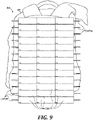
- FIG 9 is a schematic view of a portable urea dialysis system 100 in accordance with an embodiment of the present technology.
- the illustrated system 100 includes multiple cells 720-i having multiple dialysate inlets and outlets 734, 736.
- the flow through the cells 720-i may be arranged as shown in Figures 7-9 .
- size of the urea dialysis system 100 may be reduced to such an extent that the system becomes portable, for example, the system may be fitted within a backpack or other carrier 105.
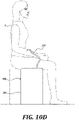
- FIGS 10A-10D are schematic views of portable dialysis systems in accordance with embodiments of the present technology.
- the compactness of the dialysis system may enable wearability or portability of the system. Such wearability/portability of the dialysis system promotes mobility and quality of life of the patient.
- Figure 10A illustrates a portable dialysis system 100 that is attached to a body of the patient 5.
- the portable dialysis system 100 is connected to the vascular system of the patient with a tube 110, with other possible embodiments of vascular access locations.
- Figure 10B illustrates a portable dialysis system 100 that includes the urea treatment unit 720 that can be fitted within the backpack 105.
- Figure 10C illustrates a portable dialysis system 100 that includes the urea treatment unit 720 that can be fitted within a suitcase 105.
- Figure 10D illustrates a portable dialysis system 100 that includes the urea treatment unit that can be fitted within a case 105.
- Other examples of the portable dialysis system 100 are also possible in different embodiments.
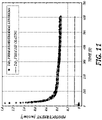
- Figure 11 is a graph of photocurrent in accordance with an embodiment of the present technology.
- the horizontal axis of the graph shows time in seconds, and the vertical axis shows the photocurrent in mA/cm 2 .
- Data were obtained by illuminating the TiO 2 nanostructures that were manufactured by hydrothermal synthesis (upper curve) and dip coating (lower curve).
- the LED is turned on (50 mA) at 5 s into the measurements; 0V is applied to TiO 2 ; and static urea/NaCl solution is used.
- the TiO 2 film that was made by hydrothermal synthesis shows high initial current. This initial current is mass-transport limited and has about 8X higher steady state photocurrent than the TiO 2 film that was prepared by dip coating.
- the effective LED intensity on the TiO 2 /FTO substrate was 4 mW/cm 2 .
- Figure 12 is a graph of photocurrent as a function of hydrothermal growth time in accordance with an embodiment of the present technology.
- the horizontal axis of the graph shows time in seconds, and the vertical axis shows the photocurrent in mA/cm 2 .
- the effective LED intensity on TiO 2 /FTO substrate was 4 mW/cm 2 .
- a steady state photocurrent as a function of hydrothermal growth time shows optimal growth time at about 185 min (corresponding to the maximum photocurrent).
- Figure 13 is a graph of absorbance as a function of wavelength in accordance with an embodiment of the present technology.
- the horizontal axis of the graph shows wavelength of the incoming light in nanometers, and the vertical axis shows the absorbance in atomic units.
- Ultraviolet light absorbance spectra generally increases with the hydrothermal growth time (the time steps being the same as those shown sequentially in Figure 12 above).
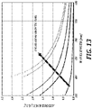
- Figure 14 is a graph of photocurrent as a function of effective LED current (light intensity) in accordance with an embodiment of the present technology.
- the horizontal axis of the graph shows effective LED current in mA
- the vertical axis shows the photocurrent in mA/cm 2 .
- the round symbols correspond to the applied cathode-to-anode voltage potential of 0.8 V
- the diamond symbols correspond to the case with no cathode-to-anode voltage.
- the graph shows a steady state photocurrent increase significantly with +0.8V applied bias to the TiO 2 anode. The increase is due to separating electron hole pairs in TiO 2 , pushing holes to reaction surface and drawing electrons into cathode circuit.
- the effective LED current is the portion of the LED current that is responsible for the photons incident on the substrate being tested (the LED having 40% quantum efficiency). Due to the device geometry, only 6.7% of emitted photons were incident on the TiO 2 surface (i.e., on the TiO 2 substrate surface).
- Figure 15 is a performance comparison between a Pt-coated and a Pt-black cathode in accordance with an embodiment of the present technology.
- the horizontal axis of the graph shows time in seconds, and the vertical axis shows the photocurrent in mA/cm 2 .
- the LED light was turned on at about 5 s with 0 V applied to anode, and with a static urea solution.
- the effective LED intensity on TiO 2 /FTO substrate was 4 mW/cm 2 .
- air bubbles (2 mL/min) were introduced at 370 s. This event causes the sudden increase in the photocurrent for the Pt-black cathode. Nevertheless, the Pt-coated cathode consistently outperformed the Pt-black cathode in terms of the photocurrent.
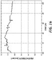
- Figure 16 is a graph of photocurrent as a function of time in accordance with an embodiment of the present technology.
- the effective LED intensity on TiO 2 /FTO substrate was 4 mW/cm 2 .
- the results demonstrate almost continuous operation of a prototype device running for over 100 h in a circulated (0.3 ml/min) solution of 10 mM urea and 0.15 M NaCl.
Landscapes
- Health & Medical Sciences (AREA)
- Life Sciences & Earth Sciences (AREA)
- Engineering & Computer Science (AREA)
- Heart & Thoracic Surgery (AREA)
- Chemical & Material Sciences (AREA)
- Public Health (AREA)
- Veterinary Medicine (AREA)
- General Health & Medical Sciences (AREA)
- Animal Behavior & Ethology (AREA)
- Biomedical Technology (AREA)
- Anesthesiology (AREA)
- Hematology (AREA)
- Vascular Medicine (AREA)
- Organic Chemistry (AREA)
- Chemical Kinetics & Catalysis (AREA)
- Epidemiology (AREA)
- Urology & Nephrology (AREA)
- Materials Engineering (AREA)
- Environmental & Geological Engineering (AREA)
- Hydrology & Water Resources (AREA)
- Water Supply & Treatment (AREA)
- Molecular Biology (AREA)
- Biodiversity & Conservation Biology (AREA)
- Cell Biology (AREA)
- Emergency Medicine (AREA)
- General Chemical & Material Sciences (AREA)
- Electrochemistry (AREA)
- Toxicology (AREA)
- External Artificial Organs (AREA)
- Physical Water Treatments (AREA)
- Treatment Of Water By Oxidation Or Reduction (AREA)
- Medicinal Chemistry (AREA)
- Organic Low-Molecular-Weight Compounds And Preparation Thereof (AREA)
- Physical Or Chemical Processes And Apparatus (AREA)
- Separation Using Semi-Permeable Membranes (AREA)
- Oxygen, Ozone, And Oxides In General (AREA)
Claims (15)
- Dialyseflüssigkeitsregenerationssystem, umfassend:eine nanostrukturierte Anode (722);eine Lichtquelle (750), die konfiguriert ist, um die Anode zu beleuchten; undeine Kathode (742), die sauerstoffdurchlässig ist, wobei die Kathode eine luftdurchlässige Kathode ist, die Flüssigkeiten blockiert, aber Gase durchlässt;wobei das System konfiguriert ist, um Dialyseflüssigkeit zu regenerieren, indem die Dialyseflüssigkeit durch das System fließt und die Anode mit der Lichtquelle beleuchtet wird, wenn die Dialyseflüssigkeit über die Anode fließt, wodurch der Harnstoff in der Dialyseflüssigkeit photoelektrochemisch entfernt wird.
- Dialyseflüssigkeitsregenerationssystem nach Anspruch 1, wobei die Dialyseflüssigkeit ein Dialysat ist.
- Dialyseflüssigkeitsregenerationssystem nach Anspruch 1, wobei es sich bei dem System um ein Nierendialysesystem, ein Hämofiltrationssystem, ein Hämodialysesystem oder ein Hämodiafiltrationssystem handelt.
- Dialyseflüssigkeitsregenerationssystem nach Anspruch 1, das ferner eine elektrische Spannungsquelle umfasst, die betriebsmäßig mit der Anode und der Kathode gekoppelt ist, wobei die elektrische Spannungsquelle optional transportabel ist.
- System nach Anspruch 1, wobei das Dialyseflüssigkeitsregenerationssystem transportabel ist.
- Dialyseflüssigkeitsregenerationssystem nach Anspruch 1, wobei das Dialyseflüssigkeitsregenerationssystem tragbar ist.
- Dialyseflüssigkeitsregenerationssystem nach Anspruch 1, wobei die Anode, die Lichtquelle und die sauerstoffdurchlässige Kathode Teile einer Dialyseflüssigkeitsregenerationszelle sind und wobei das Dialyseflüssigkeitsregenerationssystem eine Vielzahl von zusätzlichen Dialyseflüssigkeitsregenerationszellen umfasst.
- Dialyseflüssigkeitsregenerationssystem nach Anspruch 1, wobei die Kathode eine luftatmungsfähige Kathode ist.
- Dialyseflüssigkeitsregenerationssystem nach Anspruch 8, wobei: die Kathode eine leitfähige Kathode auf Stoffbasis ist, die optional ein platinbeschichteter Stoff ist; oder die Kathode eine leitfähige Kathode auf Papierbasis ist.
- Dialyseflüssigkeitsregenerationssystem nach Anspruch 1, wobei das Nanomaterial der Anode konfiguriert ist, um bei Aussetzung an Licht Photoelektronen oder Löcher zu erzeugen.
- Dialyseflüssigkeitsregenerationssystem nach Anspruch 1, wobei die Lichtquelle eine Anordnung von Leuchtdioden (LEDs) umfasst und optional wobei die LEDs in einer zweidimensionalen (2D) Anordnung angeordnet sind.
- Dialyseflüssigkeitsregenerationssystem nach Anspruch 11, wobei: die LEDs eine Bestrahlungsstärke von weniger als 4 mW/cm2 an einer Oberfläche der Anode erzeugen; oder die LEDs Licht mit einer Wellenlänge von 365 nm ausstrahlt; oder der Wirkungsgrad von einfallenden Photonen zu Photoelektronen etwa 51 % beträgt.
- Dialyseflüssigkeitsregenerationssystem nach Anspruch 1, wobei die nanostrukturierte Anode TiO2-Nanodrähte umfasst.
- Dialyseflüssigkeitsregenerationssystem nach Anspruch 13, wobei: einzelne Nanodrähte eine Dicke von etwa 500 nm aufweisen; oder die TiO2-Nanodrähte hydrothermal hergestellt werden; oder die Nanodrähte auf einem Substrat angeordnet sind, und wobei die einzelnen Nanodrähte einzeln elektrisch mit einem Substrat gekoppelt sind, das die Nanodrähte trägt.
- Dialyseflüssigkeitsregenerationssystem nach Anspruch 1, das ferner Folgendes umfasst: einen Radikalfänger, der konfiguriert ist, um oxidative Nebenprodukte, radikalische Nebenprodukte und Chlor zu entfernen; oder eine Membran, die konfiguriert ist, um kleine Moleküle durchzulassen und große Moleküle am Durchgang zu hindern, wobei die Membran eine Umkehrosmose (UO)-Membran ist.
Priority Applications (1)
| Application Number | Priority Date | Filing Date | Title |
|---|---|---|---|
| EP22168726.2A EP4091646B1 (de) | 2018-08-17 | 2019-07-31 | Vorrichtung und verfahren zur harnstoffphotooxidation |
Applications Claiming Priority (2)
| Application Number | Priority Date | Filing Date | Title |
|---|---|---|---|
| US201862719549P | 2018-08-17 | 2018-08-17 | |
| PCT/US2019/044285 WO2020036732A1 (en) | 2018-08-17 | 2019-07-31 | Apparatus and method for urea photo-oxidation |
Related Child Applications (2)
| Application Number | Title | Priority Date | Filing Date |
|---|---|---|---|
| EP22168726.2A Division EP4091646B1 (de) | 2018-08-17 | 2019-07-31 | Vorrichtung und verfahren zur harnstoffphotooxidation |
| EP22168726.2A Division-Into EP4091646B1 (de) | 2018-08-17 | 2019-07-31 | Vorrichtung und verfahren zur harnstoffphotooxidation |
Publications (3)
| Publication Number | Publication Date |
|---|---|
| EP3749385A1 EP3749385A1 (de) | 2020-12-16 |
| EP3749385A4 EP3749385A4 (de) | 2021-05-19 |
| EP3749385B1 true EP3749385B1 (de) | 2022-05-25 |
Family
ID=69524859
Family Applications (2)
| Application Number | Title | Priority Date | Filing Date |
|---|---|---|---|
| EP22168726.2A Active EP4091646B1 (de) | 2018-08-17 | 2019-07-31 | Vorrichtung und verfahren zur harnstoffphotooxidation |
| EP19849083.1A Active EP3749385B1 (de) | 2018-08-17 | 2019-07-31 | Vorrichtung zur harnstoffphotooxidation |
Family Applications Before (1)
| Application Number | Title | Priority Date | Filing Date |
|---|---|---|---|
| EP22168726.2A Active EP4091646B1 (de) | 2018-08-17 | 2019-07-31 | Vorrichtung und verfahren zur harnstoffphotooxidation |
Country Status (17)
| Country | Link |
|---|---|
| EP (2) | EP4091646B1 (de) |
| JP (1) | JP7488251B2 (de) |
| KR (2) | KR102783086B1 (de) |
| CN (1) | CN112040999B (de) |
| AU (2) | AU2019320727B2 (de) |
| BR (1) | BR112020022074B1 (de) |
| CA (1) | CA3108771C (de) |
| DK (1) | DK3749385T3 (de) |
| ES (2) | ES3017333T3 (de) |
| IL (2) | IL277205B (de) |
| MX (1) | MX2020009679A (de) |
| NZ (1) | NZ772265A (de) |
| PT (1) | PT3749385T (de) |
| SG (1) | SG11202100659TA (de) |
| TW (1) | TWI818055B (de) |
| WO (1) | WO2020036732A1 (de) |
| ZA (1) | ZA202101012B (de) |
Families Citing this family (2)
| Publication number | Priority date | Publication date | Assignee | Title |
|---|---|---|---|---|
| US10973971B2 (en) | 2018-08-17 | 2021-04-13 | University Of Washington | Apparatus and method for urea photo-oxidation |
| EP4319833A4 (de) * | 2021-04-06 | 2025-02-26 | University of Washington | Dialysesystem mit einem toxinentfernungskreislauf |
Family Cites Families (31)
| Publication number | Priority date | Publication date | Assignee | Title |
|---|---|---|---|---|
| US4370983A (en) * | 1971-01-20 | 1983-02-01 | Lichtenstein Eric Stefan | Computer-control medical care system |
| US3994799A (en) * | 1973-04-17 | 1976-11-30 | Yao Shang J | Blood and tissue detoxification apparatus |
| DE3040470A1 (de) * | 1980-10-27 | 1982-06-03 | Siemens AG, 1000 Berlin und 8000 München | Verfahren und vorrichtung zur indirekten oxidation von harnstoff |
| SU1668925A1 (ru) * | 1989-02-03 | 1991-08-07 | Московский энергетический институт | Способ определени содержани мочевины в протоке диализирующего раствора и устройство дл его осуществлени |
| WO1992003202A2 (en) * | 1990-08-20 | 1992-03-05 | Abbott Laboratories | Medical drug formulation and delivery system |
| US5247434A (en) * | 1991-04-19 | 1993-09-21 | Althin Medical, Inc. | Method and apparatus for kidney dialysis |
| EP0931581B1 (de) * | 1996-08-20 | 2005-04-06 | Ebara Corporation | Methode und vorrichtung zur reinigung eines verunreinigungen enthaltenden gases |
| DE19723462A1 (de) * | 1997-06-05 | 1998-12-10 | Thomas Dr Bluemchen | Mikrowellengassensor und Verfahren der Mikrowellenspektroskopie |
| AUPR748501A0 (en) * | 2001-09-04 | 2001-09-27 | Life Therapeutics Limited | Renal dialysis |
| US7122106B2 (en) * | 2002-05-23 | 2006-10-17 | Battelle Memorial Institute | Electrosynthesis of nanofibers and nano-composite films |
| US20100098877A1 (en) * | 2003-03-07 | 2010-04-22 | Cooper Christopher H | Large scale manufacturing of nanostructured material |
| US7435342B2 (en) * | 2003-12-24 | 2008-10-14 | Chemica Technologies, Inc. | Dialysate regeneration system for portable human dialysis |
| JP4855854B2 (ja) * | 2006-07-10 | 2012-01-18 | 川澄化学工業株式会社 | 血液透析用化学発光式尿素センサ及び血液透析における尿素測定方法 |
| US8597505B2 (en) * | 2007-09-13 | 2013-12-03 | Fresenius Medical Care Holdings, Inc. | Portable dialysis machine |
| KR20110033866A (ko) * | 2008-07-22 | 2011-03-31 | 메사추세츠 인스티튜트 오브 테크놀로지 | 증폭된 동전기 유체 펌핑 스위칭 및 담수화 |
| JP5605994B2 (ja) * | 2009-02-26 | 2014-10-15 | 株式会社バイオフォトケモニクス研究所 | バイオマス・有機・無機化合物または廃棄物・廃液を高効率で光分解浄化し同時に電力を発生するバイオ光化学電池と、該バイオ光化学電池を用いて該化合物や液体を光分解浄化すると同時に電力を発生させる方法 |
| US9005440B2 (en) * | 2009-03-06 | 2015-04-14 | Baxter International Inc. | Hemodialysis and peritoneal dialysis systems having electrodialysis and electrodeionization capabilities |
| US8404091B2 (en) * | 2009-08-27 | 2013-03-26 | Baxter International Inc. | Dialysis treatment devices for removing urea |
| US8562929B2 (en) * | 2010-04-02 | 2013-10-22 | Ohio University | Selective catalytic reduction via electrolysis of urea |
| JP2013541662A (ja) * | 2010-08-23 | 2013-11-14 | オハイオ・ユニバーシティ | 尿素の電気分解による選択的触媒還元 |
| JP6001660B2 (ja) * | 2011-08-02 | 2016-10-05 | メドトロニック,インコーポレイテッド | 制御された追従的な容積を有する流路を有する血液透析システム |
| US8987706B2 (en) * | 2012-12-10 | 2015-03-24 | The Hong Kong Polytechnic University | Highly conductive nano-structures incorporated in semiconductor nanocomposites |
| CN104870372A (zh) * | 2012-12-24 | 2015-08-26 | 皇家飞利浦有限公司 | 离子吸收/解吸装置和其方法以及ph调节器 |
| WO2014146029A1 (en) * | 2013-03-15 | 2014-09-18 | Jones Gary W | Multispectral therapeutic light source |
| JP6327870B2 (ja) * | 2014-01-29 | 2018-05-23 | デクセリアルズ株式会社 | 金属ナノワイヤー、透明導電膜及びその製造方法、分散液、情報入力装置、並びに、電子機器 |
| DE102014104768A1 (de) * | 2014-04-03 | 2015-10-29 | B. Braun Avitum Ag | Vorrichtung und Verfahren zum Bestimmen eines Verteilungsvolumens bei einem Dialysepatienten |
| EP3827853A1 (de) * | 2015-09-25 | 2021-06-02 | Medtronic, Inc. | Systeme und verfahren zur selektiven sorptionsmittelbasierten regenerationsdialyse |
| US10463776B2 (en) * | 2015-12-31 | 2019-11-05 | Baxter International Inc. | Methods and apparatuses using urea permselective diffusion through charged membranes |
| US10391222B2 (en) * | 2015-12-31 | 2019-08-27 | Baxter International Inc. | Devices for urea electrolysis and methods of using same |
| US10577248B2 (en) * | 2016-05-24 | 2020-03-03 | Harper Biotech LLC | Methods and systems for large scale carbon dioxide utilization from Lake Kivu via a CO2 industrial utilization hub integrated with electric power production and optional cryo-energy storage |
| KR20180089153A (ko) * | 2017-01-31 | 2018-08-08 | 한림대학교 산학협력단 | 이산화티타늄 광촉매를 이용한 요소 분해 방법 |
-
2019
- 2019-07-31 CN CN201980028097.8A patent/CN112040999B/zh active Active
- 2019-07-31 TW TW108127286A patent/TWI818055B/zh active
- 2019-07-31 MX MX2020009679A patent/MX2020009679A/es unknown
- 2019-07-31 ES ES22168726T patent/ES3017333T3/es active Active
- 2019-07-31 EP EP22168726.2A patent/EP4091646B1/de active Active
- 2019-07-31 DK DK19849083.1T patent/DK3749385T3/da active
- 2019-07-31 CA CA3108771A patent/CA3108771C/en active Active
- 2019-07-31 PT PT198490831T patent/PT3749385T/pt unknown
- 2019-07-31 BR BR112020022074-4A patent/BR112020022074B1/pt active IP Right Grant
- 2019-07-31 EP EP19849083.1A patent/EP3749385B1/de active Active
- 2019-07-31 ES ES19849083T patent/ES2920480T3/es active Active
- 2019-07-31 AU AU2019320727A patent/AU2019320727B2/en active Active
- 2019-07-31 IL IL277205A patent/IL277205B/en unknown
- 2019-07-31 JP JP2021504218A patent/JP7488251B2/ja active Active
- 2019-07-31 KR KR1020227024775A patent/KR102783086B1/ko active Active
- 2019-07-31 SG SG11202100659TA patent/SG11202100659TA/en unknown
- 2019-07-31 WO PCT/US2019/044285 patent/WO2020036732A1/en not_active Ceased
- 2019-07-31 KR KR1020217005785A patent/KR102424503B1/ko active Active
- 2019-07-31 NZ NZ772265A patent/NZ772265A/en unknown
- 2019-07-31 IL IL294390A patent/IL294390B2/en unknown
-
2021
- 2021-02-15 ZA ZA2021/01012A patent/ZA202101012B/en unknown
-
2022
- 2022-06-03 AU AU2022203849A patent/AU2022203849B2/en active Active
Also Published As
Similar Documents
| Publication | Publication Date | Title |
|---|---|---|
| US11684707B2 (en) | Apparatus and method for urea photo-oxidation | |
| EP1412001B1 (de) | Photolytische zelle für den physiologischen gasaustausch | |
| AU2022203849B2 (en) | Apparatus and method for urea photo-oxidation | |
| US7718144B2 (en) | Photolytic cell for providing physiological gas exchange | |
| US11629073B2 (en) | Hybrid system for water treatment, desalination, and chemical production | |
| HK40083893B (en) | Apparatus and method for urea photo-oxidation | |
| HK40083893A (en) | Apparatus and method for urea photo-oxidation | |
| HK40039542B (zh) | 用於尿素光氧化的设备和方法 | |
| HK40039542A (en) | Apparatus and method for urea photo-oxidation | |
| RU2388702C2 (ru) | Способ электрохимической очистки воды | |
| EP3990395A1 (de) | Modulares photokatalytisches system | |
| BR122022015169B1 (pt) | Sistema de regeneração de fluido de diálise, método para regenerar um fluido de diálise, método para diálise renal e método para preparar um fluido de diálise | |
| JPWO2020036732A5 (de) |
Legal Events
| Date | Code | Title | Description |
|---|---|---|---|
| STAA | Information on the status of an ep patent application or granted ep patent |
Free format text: STATUS: THE INTERNATIONAL PUBLICATION HAS BEEN MADE |
|
| PUAI | Public reference made under article 153(3) epc to a published international application that has entered the european phase |
Free format text: ORIGINAL CODE: 0009012 |
|
| STAA | Information on the status of an ep patent application or granted ep patent |
Free format text: STATUS: REQUEST FOR EXAMINATION WAS MADE |
|
| 17P | Request for examination filed |
Effective date: 20200907 |
|
| AK | Designated contracting states |
Kind code of ref document: A1 Designated state(s): AL AT BE BG CH CY CZ DE DK EE ES FI FR GB GR HR HU IE IS IT LI LT LU LV MC MK MT NL NO PL PT RO RS SE SI SK SM TR |
|
| AX | Request for extension of the european patent |
Extension state: BA ME |
|
| A4 | Supplementary search report drawn up and despatched |
Effective date: 20210415 |
|
| RIC1 | Information provided on ipc code assigned before grant |
Ipc: A61M 1/16 20060101AFI20210409BHEP Ipc: A61M 1/14 20060101ALI20210409BHEP Ipc: A61M 1/34 20060101ALI20210409BHEP Ipc: B01J 21/06 20060101ALI20210409BHEP Ipc: B01J 35/00 20060101ALI20210409BHEP |
|
| DAV | Request for validation of the european patent (deleted) | ||
| DAX | Request for extension of the european patent (deleted) | ||
| GRAP | Despatch of communication of intention to grant a patent |
Free format text: ORIGINAL CODE: EPIDOSNIGR1 |
|
| STAA | Information on the status of an ep patent application or granted ep patent |
Free format text: STATUS: GRANT OF PATENT IS INTENDED |
|
| INTG | Intention to grant announced |
Effective date: 20211208 |
|
| GRAS | Grant fee paid |
Free format text: ORIGINAL CODE: EPIDOSNIGR3 |
|
| GRAA | (expected) grant |
Free format text: ORIGINAL CODE: 0009210 |
|
| STAA | Information on the status of an ep patent application or granted ep patent |
Free format text: STATUS: THE PATENT HAS BEEN GRANTED |
|
| AK | Designated contracting states |
Kind code of ref document: B1 Designated state(s): AL AT BE BG CH CY CZ DE DK EE ES FI FR GB GR HR HU IE IS IT LI LT LU LV MC MK MT NL NO PL PT RO RS SE SI SK SM TR |
|
| REG | Reference to a national code |
Ref country code: GB Ref legal event code: FG4D |
|
| REG | Reference to a national code |
Ref country code: CH Ref legal event code: EP |
|
| REG | Reference to a national code |
Ref country code: DE Ref legal event code: R096 Ref document number: 602019015282 Country of ref document: DE |
|
| REG | Reference to a national code |
Ref country code: AT Ref legal event code: REF Ref document number: 1494008 Country of ref document: AT Kind code of ref document: T Effective date: 20220615 |
|
| REG | Reference to a national code |
Ref country code: IE Ref legal event code: FG4D |
|
| REG | Reference to a national code |
Ref country code: PT Ref legal event code: SC4A Ref document number: 3749385 Country of ref document: PT Date of ref document: 20220704 Kind code of ref document: T Free format text: AVAILABILITY OF NATIONAL TRANSLATION Effective date: 20220628 Ref country code: DK Ref legal event code: T3 Effective date: 20220629 |
|
| REG | Reference to a national code |
Ref country code: SE Ref legal event code: TRGR |
|
| REG | Reference to a national code |
Ref country code: NL Ref legal event code: FP |
|
| REG | Reference to a national code |
Ref country code: ES Ref legal event code: FG2A Ref document number: 2920480 Country of ref document: ES Kind code of ref document: T3 Effective date: 20220804 |
|
| REG | Reference to a national code |
Ref country code: LT Ref legal event code: MG9D |
|
| REG | Reference to a national code |
Ref country code: GR Ref legal event code: EP Ref document number: 20220401703 Country of ref document: GR Effective date: 20221010 |
|
| PG25 | Lapsed in a contracting state [announced via postgrant information from national office to epo] |
Ref country code: NO Free format text: LAPSE BECAUSE OF FAILURE TO SUBMIT A TRANSLATION OF THE DESCRIPTION OR TO PAY THE FEE WITHIN THE PRESCRIBED TIME-LIMIT Effective date: 20220825 Ref country code: LT Free format text: LAPSE BECAUSE OF FAILURE TO SUBMIT A TRANSLATION OF THE DESCRIPTION OR TO PAY THE FEE WITHIN THE PRESCRIBED TIME-LIMIT Effective date: 20220525 Ref country code: HR Free format text: LAPSE BECAUSE OF FAILURE TO SUBMIT A TRANSLATION OF THE DESCRIPTION OR TO PAY THE FEE WITHIN THE PRESCRIBED TIME-LIMIT Effective date: 20220525 Ref country code: FI Free format text: LAPSE BECAUSE OF FAILURE TO SUBMIT A TRANSLATION OF THE DESCRIPTION OR TO PAY THE FEE WITHIN THE PRESCRIBED TIME-LIMIT Effective date: 20220525 Ref country code: BG Free format text: LAPSE BECAUSE OF FAILURE TO SUBMIT A TRANSLATION OF THE DESCRIPTION OR TO PAY THE FEE WITHIN THE PRESCRIBED TIME-LIMIT Effective date: 20220825 |
|
| PG25 | Lapsed in a contracting state [announced via postgrant information from national office to epo] |
Ref country code: RS Free format text: LAPSE BECAUSE OF FAILURE TO SUBMIT A TRANSLATION OF THE DESCRIPTION OR TO PAY THE FEE WITHIN THE PRESCRIBED TIME-LIMIT Effective date: 20220525 Ref country code: LV Free format text: LAPSE BECAUSE OF FAILURE TO SUBMIT A TRANSLATION OF THE DESCRIPTION OR TO PAY THE FEE WITHIN THE PRESCRIBED TIME-LIMIT Effective date: 20220525 Ref country code: IS Free format text: LAPSE BECAUSE OF FAILURE TO SUBMIT A TRANSLATION OF THE DESCRIPTION OR TO PAY THE FEE WITHIN THE PRESCRIBED TIME-LIMIT Effective date: 20220925 |
|
| PG25 | Lapsed in a contracting state [announced via postgrant information from national office to epo] |
Ref country code: SM Free format text: LAPSE BECAUSE OF FAILURE TO SUBMIT A TRANSLATION OF THE DESCRIPTION OR TO PAY THE FEE WITHIN THE PRESCRIBED TIME-LIMIT Effective date: 20220525 Ref country code: SK Free format text: LAPSE BECAUSE OF FAILURE TO SUBMIT A TRANSLATION OF THE DESCRIPTION OR TO PAY THE FEE WITHIN THE PRESCRIBED TIME-LIMIT Effective date: 20220525 Ref country code: RO Free format text: LAPSE BECAUSE OF FAILURE TO SUBMIT A TRANSLATION OF THE DESCRIPTION OR TO PAY THE FEE WITHIN THE PRESCRIBED TIME-LIMIT Effective date: 20220525 Ref country code: EE Free format text: LAPSE BECAUSE OF FAILURE TO SUBMIT A TRANSLATION OF THE DESCRIPTION OR TO PAY THE FEE WITHIN THE PRESCRIBED TIME-LIMIT Effective date: 20220525 Ref country code: CZ Free format text: LAPSE BECAUSE OF FAILURE TO SUBMIT A TRANSLATION OF THE DESCRIPTION OR TO PAY THE FEE WITHIN THE PRESCRIBED TIME-LIMIT Effective date: 20220525 |
|
| PG25 | Lapsed in a contracting state [announced via postgrant information from national office to epo] |
Ref country code: MC Free format text: LAPSE BECAUSE OF FAILURE TO SUBMIT A TRANSLATION OF THE DESCRIPTION OR TO PAY THE FEE WITHIN THE PRESCRIBED TIME-LIMIT Effective date: 20220525 |
|
| REG | Reference to a national code |
Ref country code: DE Ref legal event code: R097 Ref document number: 602019015282 Country of ref document: DE |
|
| PG25 | Lapsed in a contracting state [announced via postgrant information from national office to epo] |
Ref country code: AL Free format text: LAPSE BECAUSE OF FAILURE TO SUBMIT A TRANSLATION OF THE DESCRIPTION OR TO PAY THE FEE WITHIN THE PRESCRIBED TIME-LIMIT Effective date: 20220525 |
|
| PLBE | No opposition filed within time limit |
Free format text: ORIGINAL CODE: 0009261 |
|
| STAA | Information on the status of an ep patent application or granted ep patent |
Free format text: STATUS: NO OPPOSITION FILED WITHIN TIME LIMIT |
|
| PG25 | Lapsed in a contracting state [announced via postgrant information from national office to epo] |
Ref country code: LU Free format text: LAPSE BECAUSE OF NON-PAYMENT OF DUE FEES Effective date: 20220731 |
|
| 26N | No opposition filed |
Effective date: 20230228 |
|
| PG25 | Lapsed in a contracting state [announced via postgrant information from national office to epo] |
Ref country code: SI Free format text: LAPSE BECAUSE OF FAILURE TO SUBMIT A TRANSLATION OF THE DESCRIPTION OR TO PAY THE FEE WITHIN THE PRESCRIBED TIME-LIMIT Effective date: 20220525 |
|
| P01 | Opt-out of the competence of the unified patent court (upc) registered |
Effective date: 20230426 |
|
| REG | Reference to a national code |
Ref country code: AT Ref legal event code: UEP Ref document number: 1494008 Country of ref document: AT Kind code of ref document: T Effective date: 20220525 |
|
| PG25 | Lapsed in a contracting state [announced via postgrant information from national office to epo] |
Ref country code: MK Free format text: LAPSE BECAUSE OF FAILURE TO SUBMIT A TRANSLATION OF THE DESCRIPTION OR TO PAY THE FEE WITHIN THE PRESCRIBED TIME-LIMIT Effective date: 20220525 Ref country code: CY Free format text: LAPSE BECAUSE OF FAILURE TO SUBMIT A TRANSLATION OF THE DESCRIPTION OR TO PAY THE FEE WITHIN THE PRESCRIBED TIME-LIMIT Effective date: 20220525 |
|
| PG25 | Lapsed in a contracting state [announced via postgrant information from national office to epo] |
Ref country code: HU Free format text: LAPSE BECAUSE OF FAILURE TO SUBMIT A TRANSLATION OF THE DESCRIPTION OR TO PAY THE FEE WITHIN THE PRESCRIBED TIME-LIMIT; INVALID AB INITIO Effective date: 20190731 |
|
| PG25 | Lapsed in a contracting state [announced via postgrant information from national office to epo] |
Ref country code: TR Free format text: LAPSE BECAUSE OF FAILURE TO SUBMIT A TRANSLATION OF THE DESCRIPTION OR TO PAY THE FEE WITHIN THE PRESCRIBED TIME-LIMIT Effective date: 20220525 |
|
| PG25 | Lapsed in a contracting state [announced via postgrant information from national office to epo] |
Ref country code: MT Free format text: LAPSE BECAUSE OF FAILURE TO SUBMIT A TRANSLATION OF THE DESCRIPTION OR TO PAY THE FEE WITHIN THE PRESCRIBED TIME-LIMIT Effective date: 20220525 |
|
| PG25 | Lapsed in a contracting state [announced via postgrant information from national office to epo] |
Ref country code: BG Free format text: LAPSE BECAUSE OF FAILURE TO SUBMIT A TRANSLATION OF THE DESCRIPTION OR TO PAY THE FEE WITHIN THE PRESCRIBED TIME-LIMIT Effective date: 20220525 |
|
| PG25 | Lapsed in a contracting state [announced via postgrant information from national office to epo] |
Ref country code: BG Free format text: LAPSE BECAUSE OF FAILURE TO SUBMIT A TRANSLATION OF THE DESCRIPTION OR TO PAY THE FEE WITHIN THE PRESCRIBED TIME-LIMIT Effective date: 20220525 |
|
| PGFP | Annual fee paid to national office [announced via postgrant information from national office to epo] |
Ref country code: NL Payment date: 20250704 Year of fee payment: 7 |
|
| PGFP | Annual fee paid to national office [announced via postgrant information from national office to epo] |
Ref country code: ES Payment date: 20250804 Year of fee payment: 7 Ref country code: PT Payment date: 20250709 Year of fee payment: 7 |
|
| PGFP | Annual fee paid to national office [announced via postgrant information from national office to epo] |
Ref country code: DE Payment date: 20250702 Year of fee payment: 7 Ref country code: DK Payment date: 20250714 Year of fee payment: 7 |
|
| PGFP | Annual fee paid to national office [announced via postgrant information from national office to epo] |
Ref country code: GR Payment date: 20250716 Year of fee payment: 7 |
|
| PGFP | Annual fee paid to national office [announced via postgrant information from national office to epo] |
Ref country code: PL Payment date: 20250725 Year of fee payment: 7 Ref country code: IT Payment date: 20250722 Year of fee payment: 7 |
|
| PGFP | Annual fee paid to national office [announced via postgrant information from national office to epo] |
Ref country code: BE Payment date: 20250703 Year of fee payment: 7 Ref country code: GB Payment date: 20250703 Year of fee payment: 7 |
|
| PGFP | Annual fee paid to national office [announced via postgrant information from national office to epo] |
Ref country code: AT Payment date: 20250709 Year of fee payment: 7 Ref country code: FR Payment date: 20250703 Year of fee payment: 7 |
|
| PGFP | Annual fee paid to national office [announced via postgrant information from national office to epo] |
Ref country code: CH Payment date: 20250801 Year of fee payment: 7 Ref country code: SE Payment date: 20250702 Year of fee payment: 7 |
|
| PGFP | Annual fee paid to national office [announced via postgrant information from national office to epo] |
Ref country code: IE Payment date: 20250702 Year of fee payment: 7 |