EP3749064A1 - Plasma processing machine - Google Patents
Plasma processing machine Download PDFInfo
- Publication number
- EP3749064A1 EP3749064A1 EP18903768.2A EP18903768A EP3749064A1 EP 3749064 A1 EP3749064 A1 EP 3749064A1 EP 18903768 A EP18903768 A EP 18903768A EP 3749064 A1 EP3749064 A1 EP 3749064A1
- Authority
- EP
- European Patent Office
- Prior art keywords
- section
- plasma
- plasma head
- head
- attachment
- Prior art date
- Legal status (The legal status is an assumption and is not a legal conclusion. Google has not performed a legal analysis and makes no representation as to the accuracy of the status listed.)
- Granted
Links
Images




Classifications
-
- H—ELECTRICITY
- H05—ELECTRIC TECHNIQUES NOT OTHERWISE PROVIDED FOR
- H05H—PLASMA TECHNIQUE; PRODUCTION OF ACCELERATED ELECTRICALLY-CHARGED PARTICLES OR OF NEUTRONS; PRODUCTION OR ACCELERATION OF NEUTRAL MOLECULAR OR ATOMIC BEAMS
- H05H1/00—Generating plasma; Handling plasma
- H05H1/24—Generating plasma
- H05H1/46—Generating plasma using applied electromagnetic fields, e.g. high frequency or microwave energy
- H05H1/4645—Radiofrequency discharges
- H05H1/466—Radiofrequency discharges using capacitive coupling means, e.g. electrodes
-
- B—PERFORMING OPERATIONS; TRANSPORTING
- B23—MACHINE TOOLS; METAL-WORKING NOT OTHERWISE PROVIDED FOR
- B23K—SOLDERING OR UNSOLDERING; WELDING; CLADDING OR PLATING BY SOLDERING OR WELDING; CUTTING BY APPLYING HEAT LOCALLY, e.g. FLAME CUTTING; WORKING BY LASER BEAM
- B23K10/00—Welding or cutting by means of a plasma
- B23K10/02—Plasma welding
-
- H—ELECTRICITY
- H01—ELECTRIC ELEMENTS
- H01J—ELECTRIC DISCHARGE TUBES OR DISCHARGE LAMPS
- H01J37/00—Discharge tubes with provision for introducing objects or material to be exposed to the discharge, e.g. for the purpose of examination or processing thereof
- H01J37/32—Gas-filled discharge tubes
- H01J37/32431—Constructional details of the reactor
- H01J37/3244—Gas supply means
-
- H—ELECTRICITY
- H05—ELECTRIC TECHNIQUES NOT OTHERWISE PROVIDED FOR
- H05H—PLASMA TECHNIQUE; PRODUCTION OF ACCELERATED ELECTRICALLY-CHARGED PARTICLES OR OF NEUTRONS; PRODUCTION OR ACCELERATION OF NEUTRAL MOLECULAR OR ATOMIC BEAMS
- H05H1/00—Generating plasma; Handling plasma
- H05H1/24—Generating plasma
- H05H1/26—Plasma torches
- H05H1/32—Plasma torches using an arc
- H05H1/34—Details, e.g. electrodes, nozzles
- H05H1/3423—Connecting means, e.g. electrical connecting means or fluid connections
-
- H—ELECTRICITY
- H05—ELECTRIC TECHNIQUES NOT OTHERWISE PROVIDED FOR
- H05H—PLASMA TECHNIQUE; PRODUCTION OF ACCELERATED ELECTRICALLY-CHARGED PARTICLES OR OF NEUTRONS; PRODUCTION OR ACCELERATION OF NEUTRAL MOLECULAR OR ATOMIC BEAMS
- H05H2242/00—Auxiliary systems
Definitions
- the present invention relates to a plasma processing machine for irradiating a workpiece with a plasma-converted gas to perform a treatment on a surface of the workpiece.
- a plasma processing machine that uses a plasma generating device as described in the following Patent Literature as a plasma head which is an irradiation head, moves the plasma head with respect to the workpiece by a head moving device, and performs a treatment (hereinafter, sometimes referred to as "plasma processing") on a surface of a workpiece with a plasma gas irradiated or emitted from the plasma head.
- Patent Literature 1 JP-A-2016-38940
- the present invention has been made in view of such circumstances, and an object thereof is to provide a practical plasma processing machine.
- the plasma processing machine of the present invention includes a plasma head configured to generate a plasma gas and eject the plasma gas from a nozzle; a head moving device configured to move the plasma head; and an attachment mechanism for detachably attaching the plasma head to an attachment section of the head moving device.
- the plasma processing machine of the present invention is capable of attaching and detaching the plasma head, for example, it is easy to exchange with a different type of plasma head, remove for maintenance, attach after maintenance, or the like. That is, the plasma processing machine of the present invention is highly practical because of its versatility and convenience.
- the plasma processing machine of the first example includes, as shown in Fig. 1 , table 10 on which workpiece W is placed, serial link type robot (also referred to as an articulated robot, hereinafter, simply abbreviated as a "robot") 12 arranged beside table 10, plasma head 14 held by robot 12 emitting a plasma gas, power supply and gas supply unit 16 which supplies a power to plasma head 14 and supplies a gas to plasma head 14, and controller 18 as a control device for controlling the plasma processing machine.
- robot 12 functions as a head moving device for moving plasma head 14 to irradiate workpiece W with the plasma gas.
- plasma head 14 has housing 20 generally made of ceramics, and reaction chamber 22 for generating a plasma gas is formed in housing 20.
- a pair of electrodes 24 is held so as to protrude into reaction chamber 22.
- Reaction gas flow path 26 for allowing a reaction gas to flow into reaction chamber 22 from above and a pair of carrier gas flow paths 28 for allowing a carrier gas to flow in are formed in housing 20.
- the reaction gas is oxygen (O 2 ), but from reaction gas flow path 26, a mixed gas of oxygen and nitrogen (N 2 ) (for example, dry air (air)) is caused to flow between electrodes 24 (hereinafter, this mixed gas is also referred to as “reaction gas” for convenience, and oxygen is sometimes referred to as “source gas” for convenience).
- the carrier gas is nitrogen and flows from respective carrier gas flow paths 28 so as to surround respective electrodes 24.
- the lower portion of plasma head 14 is nozzle 30, and nozzle 30 is configured with multiple emission ports 32 aligned in a line. Multiple emission passages 34 are formed so as to be connected to respective emission ports 32 downward from reaction chamber 22.
- An AC voltage is applied between a pair of electrodes 24 by the power supply section of power supply and gas supply unit 16.
- pseudo arc A is generated between the lower ends of a pair of electrodes 24 in reaction chamber 22.
- the reaction gas passes through pseudo arc A, the reaction gas is converted into plasma, and the plasma gas, which is the plasma-converted gas, is emitted (ejected) from nozzle 30 together with the carrier gas.
- sleeve 36 is provided so as to surround nozzle 30.
- a heat gas as a shield gas in the present plasma processing machine, air is employed
- the heat gas is supplied to annular cavity 38 between sleeve 36 and nozzle 30 through supply pipe 40, and the heat gas is emitted along the flow of the plasma gas so as to surround the plasma gas emitted from nozzle 30.
- the heat gas as the name implies, heated gas is emitted to ensure the effect of the plasma gas. Therefore, in the middle of supply pipe 40, heater 42 for heating is provided.
- FIG. 4 shows plasma head 14', which is an example of another plasma head.
- plasma head 14' shown in the Fig. 4 one emission port 32' having a relatively large diameter is provided at nozzle 30', and one emission passage 34' is formed so as to be connected to emission port 32' downward from reaction chamber 22.
- Sleeve 36' and annular cavity 38' are modified to match nozzle 30'. The rest of the configuration is the same as that of plasma head 14, and therefore description thereof is omitted.
- the plasma processing machine can be mounted with different type of plasma head.
- power supply and gas supply unit 16 includes a power supply section and a gas supply section.
- the power supply section has a power supply for applying a voltage between a pair of electrodes 24 of plasma head 14, and supplies electric power, for applying a voltage between electrodes 24, to plasma head 14 by wire (cable) 44a.
- a signal for control is also transmitted to plasma head 14 via wire (cable) 44b.
- the gas supply section supplies the above-mentioned reaction gas, carrier gas, and heat gas.
- the reaction gas is supplied to plasma head 14 through one gas tube 46a, the carrier gas is supplied through two gas tubes 46b and 46c, and the heat gas is supplied through one gas tube 46d.
- gas tubes 46a to 46d constitute pipelines for supplying the respective gases.
- wires 44a and 44b and gas tubes 46a to 46d may be collectively referred to as wire 44 and gas tube 46, respectively.
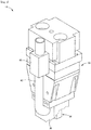
- attachment mechanism 50 for detachably attaching plasma head 14 with respect to robot 12 is provided.
- Fig. 5(a) shows a state in which plasma head 14 is attached by attachment mechanism 50
- Fig. 5(b) shows a state in which plasma head 14 is removed.
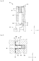
- Fig. 6 is a diagram in which a connector (described in detail later) for transmitting a signal for power supply and control to electrode 24 is omitted in order to explain attachment mechanism 50
- Fig. 6(a) is an overall view of attachment mechanism 50
- Fig. 6(b) is an enlarged view of a second engaging section to be described later.
- Fig. 7 is a diagram showing a line of sight opposite to that shown in Fig. 6(a) for explaining attachment mechanism 50.
- the attachment mechanism will be described with reference to these drawings.
- Attachment mechanism 50 is a mechanism for attaching plasma head 14 to attachment section 52 provided in the robot.
- Attachment section 52 is provided with attaching surface 54 extending in the up-down direction, which is a first direction (Z-direction) and extending in the left-right direction (X-direction), which is a second direction perpendicular to the first direction.
- plasma head 14 is provided with attached surface 56 which comes into contact with attaching surface 54 in a state where plasma head 14 is attached, in other words, fitted to attaching surface 54.
- Attachment section 52 is provided with first engaging section 58 at one side portion in the up-down direction, that is, the lower portion, and is provided with second engaging section 60 at the other side of the portion, that is, the upper portion.
- first engaging section 58 and second engaging section 60 are provided so as to sandwich attaching surface 54.
- plasma head 14 is provided with first engaged section 62 to be engaged with first engaging section 58 and second engaged section 64 to be engaged with second engaging section 60.
- First engaging section 58 has a pair of receiving sections 66 and a pair of rollers 68, each of which is disposed spaced apart from each other in the left-right direction.
- first engaged section 62 has a pair of legs 70 which are disposed spaced apart from each other in the left-right direction.
- a pair of receiving sections 66 locks the lower end of a pair of legs 70 and prohibits plasma head 14 from being displaced downward with respect to attachment section 52.
- a pair of rollers 68 prohibits plasma head 14 from being displaced in the left-right direction with respect to attachment section 52.
- a pair of rollers 68 and a pair of legs 70 constitute a second-direction displacement prohibiting mechanism for prohibiting the displacement of plasma head 14 in the second direction by prohibiting the displacement of first engaged section 62 in the second direction.
- Second engaging section 60 has a pair of rollers 72, while second engaged section 64 has gripped section 74 that is gripped by a pair of rollers 72 in a state of being engaged with second engaging section 60.
- a pair of rollers 72 and gripped section 74 constitute a second-direction displacement prohibiting mechanism for prohibiting the displacement of plasma head 14 in the second direction together with a pair of rollers 68 and a pair of legs 70 by prohibiting the displacement of second engaged section 64 in the second direction.
- biasing mechanism 76 is provided at second engaging section 60. Specifically described with reference to Fig.
- second engaging section 60 has plunger 80 which is biased downward in the first direction by spring 78, and the lower end portion of plunger 80 has a pair of inclined surfaces 82 and 84.
- second engaged section 64 has roller 86, and in a state in which second engaged section 64 is engaged with second engaging section 60, roller 86 is engaged with inclined surface 84 positioned on the rear side in a third direction perpendicular to the first direction and the second direction, that is, the front-rear direction (Y-direction). Due to the biasing force of spring 78, plunger 80 biases roller 86 downwardly.
- biasing mechanism 76 has a function of biasing plasma head 14 downward, which is one side in the first direction.
- second engaged section 64 of plasma head 14 is biased rearward by the biasing force of biasing mechanism 76.
- inclined surface 88 and inclined surface 90 which engage with each other are provided respectively, and first engaged section 62 is also biased rearward by the biasing force of biasing mechanism 76. Therefore, in the present plasma processing machine, entire plasma head 14 is biased rearward by the biasing force of biasing mechanism 76, so that attaching surface 54 of attachment section 52 and attached surface 56 of plasma head 14 are fitted together exactly.
- gas tube 46 for the supply of each gas described above is connected to the rearward portion of attachment section 52.
- the connection of the pipeline connecting each gas tube 46 to plasma head 14 is performed by each of four connectors 92 which are gas connectors in the state where plasma head 14 is attached to attachment section 52.
- attaching surface 54 is provided with four supply holes 94 corresponding to four connectors 92.
- attached surface 56 is provided with four receiving holes 96 provided at positions that respectively match four supply holes 94.
- Four connectors 92 have the same structure each other.
- supply hole 94 contains short rubber pipe 98, sleeve 100 that supports short rubber pipe 98 and has a sealed outer periphery, and spring 102 for biasing sleeve 100 forward. If plasma head 14 is not attached, although the tip end of rubber pipe 98 protrudes from attaching surface 54, but when plasma head 14 is attached, that is, in a state where attaching surface 54 and attached surface 56 are in contact with each other, rubber pipe 98 retreats against the biasing force of spring 102, and supply hole 94 and receiving hole 96 are connected while being sealed.
- attachment mechanism 50 is configured to include four connectors 92 for connecting the pipeline for the supply of gas, and each connector 92 is configured to include supply hole 94, receiving hole 96, rubber pipe 98, sleeve 100, spring 102, or the like.
- wire 44a for supplying electric power to electrode 24 of plasma head 14 and wire 44b for sending a control signal extend to the front side at the upper portion of attachment section 52, and connectors 104a and 104b are provided at the tip ends of wires 44a and 44b, respectively.
- Connectors 104a and 104b constitute attachment mechanism 50, and are connected to connectors 106a and 106b provided at plasma head 14 after plasma head 14 is attached.
- insulating layer 108 is formed on the surface of attaching surface 54. Rollers 68, 72, and 86 are made of resin, and first engaged section 62 is also made of resin. Accordingly, in a state in which plasma head 14 is attached to attachment section 52 by attachment mechanism 50, plasma head 14 are electrically insulated from attachment section 52. Inside power supply and gas supply unit 16, in order to detect disconnection, leakage, or the like, current sensor 110 (see Fig. 1 ) for measuring the current supplied through wire 44a is disposed. By the insulation, noise from plasma head 14 via robot 12 is effectively prevented from adversely affecting the current measurement of current sensor 110.
- first engaged section 62 may be locked to first engaging section 58 from obliquely upward and second engaged section 64 may be moved to the rear side in the third direction with respect to second engaging section 60 by pushing the upper portion of plasma head 14 rearward in the locked state to engage second engaged section 64 with second engaging section 60.
- the reverse operation may be performed. Specifically, after pulling the upper portion of plasma head 14 forward to separate attached surface 56 from attaching surface 54, plasma head 14 may be lifted obliquely upward.
- attachment mechanism 50 with one touch, plasma head 14 can be attached to and detached from attachment section 52.
- Same attachment mechanism 50 is also employed in another plasma head 14'.
- the present plasma processing machine is excellent in versatility because it can be easily exchanged with a different type of plasma head, and is also excellent in convenience because maintenance of the plasma head can be easily performed.
- the plasma processing machine of the second example employs attachment mechanism 50 of the same structure in attachment to attachment section 52 of the plasma head, but is different in feeding the electrodes of the plasma head, and differs in the connection of wires for supplying power to the electrodes of the plasma head and transmitting control signals, and connection of gas tubes for supplying of each gas to the plasma head.
- FIG. 10(a) showing a state in which the wire and the gas tube are connected
- Fig. 10 (b) showing a state in which the connection is released
- wire 120 for supplying power to electrode 24
- wire 122 for transmitting a control signal
- wire 124 for ground
- gas tubes 126 (only two are shown in the drawings) for supplying each gas are connected to plasma head 14" are connected at the upper portion not without using attaching surface 54 and attached surface 56.
- Wire 120, wire 122, and gas tube 126 are connected using connectors 128, 130, and 132, respectively. After attaching plasma head 14" to attachment section 52, their connections are made.
- plasma head 14 When removing plasma head 14", plasma head 14" is disconnected from attachment section 52 after the connection is released.
- wire 120, wire 122, wire 124, and gas tube 126 are inserted through cover tube 134 and are connected to a power supply and gas supply unit in a form of one relatively thick string.
- the plasma processing machine of the second example in a state in which plasma head 14" is attached, wires 120 to 124 and gas tube 126 are arranged to extend from the upper portion of plasma head 14 to the upper side which is one side in the first direction (X-direction). Accordingly, the plasma processing machine of the second example can easily perform maintenance related to the pipeline, power supply, and the like in the supply of gas, and the attachment and detachment of plasma head 14" including the attachment and detachment of gas tube 126 and wires 120 to 124 can be easily performed together with the adoption of an attachment mechanism similar to that of the plasma processing machine of the first example.
Landscapes
- Engineering & Computer Science (AREA)
- Physics & Mathematics (AREA)
- Plasma & Fusion (AREA)
- Spectroscopy & Molecular Physics (AREA)
- Mechanical Engineering (AREA)
- Chemical & Material Sciences (AREA)
- Analytical Chemistry (AREA)
- Electromagnetism (AREA)
- Plasma Technology (AREA)
Abstract
Description
- The present invention relates to a plasma processing machine for irradiating a workpiece with a plasma-converted gas to perform a treatment on a surface of the workpiece.
- In the related art, there is a plasma processing machine that uses a plasma generating device as described in the following Patent Literature as a plasma head which is an irradiation head, moves the plasma head with respect to the workpiece by a head moving device, and performs a treatment (hereinafter, sometimes referred to as "plasma processing") on a surface of a workpiece with a plasma gas irradiated or emitted from the plasma head.
- Patent Literature 1:
JP-A-2016-38940 - For the plasma processing, it is desirable to use different types of plasma heads depending on the shape of the workpiece, the degree of treatment, and the like, and it is also desirable to perform regular maintenance on the plasma heads. The present invention has been made in view of such circumstances, and an object thereof is to provide a practical plasma processing machine.
- In order to solve the above problems, the plasma processing machine of the present invention includes a plasma head configured to generate a plasma gas and eject the plasma gas from a nozzle; a head moving device configured to move the plasma head; and an attachment mechanism for detachably attaching the plasma head to an attachment section of the head moving device.
- Since the plasma processing machine of the present invention is capable of attaching and detaching the plasma head, for example, it is easy to exchange with a different type of plasma head, remove for maintenance, attach after maintenance, or the like. That is, the plasma processing machine of the present invention is highly practical because of its versatility and convenience.
-
- [
Fig. 1] Fig. 1 is a diagram showing an overall configuration of a plasma processing machine according to a first example. - [
Fig. 2] Fig. 2 is a perspective view showing a state in which a cover is removed from a plasma head of the plasma processing machine of the first example. - [
Fig. 3] Fig. 3 is a sectional view of the plasma head ofFig. 2 . - [
Fig. 4] Fig. 4 is a sectional view showing another plasma head that can be employed in the plasma processing machine of the first example. - [
Fig. 5] Fig. 5 is a diagram showing an image of attachment and detachment of the plasma head in the plasma processing machine of the first example. - [
Fig. 6] Fig. 6 is a diagram for explaining an attachment mechanism of the plasma head employed in the plasma processing machine of the first example. - [
Fig. 7] Fig. 7 is a diagram for explaining the attachment mechanism of the plasma head and is a diagram in a viewpoint opposite to that ofFig. 6 . - [
Fig. 8] Fig. 8 is a sectional view showing a biasing mechanism included in the attachment mechanism ofFigs. 6 and7 . - [
Fig. 9] Fig. 9 is a sectional view showing a structure of a connector for connecting a pipeline for supply of gas between the plasma head and an attachment section. - [
Fig. 10] Fig. 10 is a diagram showing a plasma head employed in a plasma processing machine of a second example. - Hereinafter, a representative embodiment of the present invention will be described in detail as an example with reference to the drawings. The present invention can be implemented in various modes in which various changes and improvements are made based on the knowledge of a person skilled in the art in addition to the following examples.
- The plasma processing machine of the first example includes, as shown in
Fig. 1 , table 10 on which workpiece W is placed, serial link type robot (also referred to as an articulated robot, hereinafter, simply abbreviated as a "robot") 12 arranged beside table 10,plasma head 14 held byrobot 12 emitting a plasma gas, power supply andgas supply unit 16 which supplies a power toplasma head 14 and supplies a gas toplasma head 14, andcontroller 18 as a control device for controlling the plasma processing machine. Incidentally,robot 12 functions as a head moving device for movingplasma head 14 to irradiate workpiece W with the plasma gas. - Referring to
Fig. 2 , which shows a state in which the cover is removed, andFig. 3 , which is a sectional view,plasma head 14 hashousing 20 generally made of ceramics, andreaction chamber 22 for generating a plasma gas is formed inhousing 20. A pair ofelectrodes 24 is held so as to protrude intoreaction chamber 22. Reactiongas flow path 26 for allowing a reaction gas to flow intoreaction chamber 22 from above and a pair of carriergas flow paths 28 for allowing a carrier gas to flow in are formed inhousing 20. The reaction gas (source gas) is oxygen (O2), but from reactiongas flow path 26, a mixed gas of oxygen and nitrogen (N2) (for example, dry air (air)) is caused to flow between electrodes 24 (hereinafter, this mixed gas is also referred to as "reaction gas" for convenience, and oxygen is sometimes referred to as "source gas" for convenience). The carrier gas is nitrogen and flows from respective carriergas flow paths 28 so as to surroundrespective electrodes 24. The lower portion ofplasma head 14 isnozzle 30, andnozzle 30 is configured withmultiple emission ports 32 aligned in a line.Multiple emission passages 34 are formed so as to be connected torespective emission ports 32 downward fromreaction chamber 22. - An AC voltage is applied between a pair of
electrodes 24 by the power supply section of power supply andgas supply unit 16. By this application, for example, as shown inFig. 3 , pseudo arc A is generated between the lower ends of a pair ofelectrodes 24 inreaction chamber 22. When the reaction gas passes through pseudo arc A, the reaction gas is converted into plasma, and the plasma gas, which is the plasma-converted gas, is emitted (ejected) fromnozzle 30 together with the carrier gas. - Around
nozzle 30,sleeve 36 is provided so as to surroundnozzle 30. A heat gas as a shield gas (in the present plasma processing machine, air is employed) is supplied toannular cavity 38 betweensleeve 36 andnozzle 30 throughsupply pipe 40, and the heat gas is emitted along the flow of the plasma gas so as to surround the plasma gas emitted fromnozzle 30. As the heat gas, as the name implies, heated gas is emitted to ensure the effect of the plasma gas. Therefore, in the middle ofsupply pipe 40,heater 42 for heating is provided. - In the present plasma processing machine, another plasma head can be attached to
robot 12 in place ofplasma head 14 described above.Fig. 4 shows plasma head 14', which is an example of another plasma head. In plasma head 14' shown in theFig. 4 , one emission port 32' having a relatively large diameter is provided at nozzle 30', and one emission passage 34' is formed so as to be connected to emission port 32' downward fromreaction chamber 22. Sleeve 36' and annular cavity 38' are modified to match nozzle 30'. The rest of the configuration is the same as that ofplasma head 14, and therefore description thereof is omitted. Thus, the plasma processing machine can be mounted with different type of plasma head. - Although not shown, power supply and
gas supply unit 16 includes a power supply section and a gas supply section. The power supply section has a power supply for applying a voltage between a pair ofelectrodes 24 ofplasma head 14, and supplies electric power, for applying a voltage betweenelectrodes 24, toplasma head 14 by wire (cable) 44a. A signal for control is also transmitted toplasma head 14 via wire (cable) 44b. The gas supply section supplies the above-mentioned reaction gas, carrier gas, and heat gas. The reaction gas is supplied toplasma head 14 through onegas tube 46a, the carrier gas is supplied through two gas tubes 46b and 46c, and the heat gas is supplied through onegas tube 46d. Incidentally,gas tubes 46a to 46d constitute pipelines for supplying the respective gases. In the following description,wires gas tubes 46a to 46d may be collectively referred to as wire 44 andgas tube 46, respectively. - In the present plasma processing machine, as shown in
Fig. 5 ,attachment mechanism 50 for detachably attachingplasma head 14 with respect torobot 12 is provided.Fig. 5(a) shows a state in whichplasma head 14 is attached byattachment mechanism 50, andFig. 5(b) shows a state in whichplasma head 14 is removed.Fig. 6 is a diagram in which a connector (described in detail later) for transmitting a signal for power supply and control toelectrode 24 is omitted in order to explainattachment mechanism 50,Fig. 6(a) is an overall view ofattachment mechanism 50, andFig. 6(b) is an enlarged view of a second engaging section to be described later.Fig. 7 is a diagram showing a line of sight opposite to that shown inFig. 6(a) for explainingattachment mechanism 50. Hereinafter, the attachment mechanism will be described with reference to these drawings. -
Attachment mechanism 50 is a mechanism for attachingplasma head 14 toattachment section 52 provided in the robot.Attachment section 52 is provided with attachingsurface 54 extending in the up-down direction, which is a first direction (Z-direction) and extending in the left-right direction (X-direction), which is a second direction perpendicular to the first direction. On the other hand,plasma head 14 is provided with attachedsurface 56 which comes into contact with attachingsurface 54 in a state whereplasma head 14 is attached, in other words, fitted to attachingsurface 54.Attachment section 52 is provided with first engagingsection 58 at one side portion in the up-down direction, that is, the lower portion, and is provided with second engagingsection 60 at the other side of the portion, that is, the upper portion. Briefly, first engagingsection 58 and second engagingsection 60 are provided so as tosandwich attaching surface 54. In contrast,plasma head 14 is provided with firstengaged section 62 to be engaged with first engagingsection 58 and second engagedsection 64 to be engaged with second engagingsection 60. - First engaging
section 58 has a pair of receivingsections 66 and a pair ofrollers 68, each of which is disposed spaced apart from each other in the left-right direction. On the other hand, first engagedsection 62 has a pair oflegs 70 which are disposed spaced apart from each other in the left-right direction. In a state in whichplasma head 14 is attached, that is, in a state in which first engagingsection 58 and first engagedsection 62 are engaged, a pair of receivingsections 66 locks the lower end of a pair oflegs 70 and prohibitsplasma head 14 from being displaced downward with respect toattachment section 52. Further, in that state, by the outer peripheral surface of a pair ofrollers 68 abutting on the inner surface of a pair of legs 70 (surfaces facing each other), respectively, a pair ofrollers 68 prohibitsplasma head 14 from being displaced in the left-right direction with respect toattachment section 52. In other words, a pair ofrollers 68 and a pair oflegs 70 constitute a second-direction displacement prohibiting mechanism for prohibiting the displacement ofplasma head 14 in the second direction by prohibiting the displacement of first engagedsection 62 in the second direction. - Second engaging
section 60 has a pair ofrollers 72, while second engagedsection 64 has grippedsection 74 that is gripped by a pair ofrollers 72 in a state of being engaged with second engagingsection 60. A pair ofrollers 72 and grippedsection 74 constitute a second-direction displacement prohibiting mechanism for prohibiting the displacement ofplasma head 14 in the second direction together with a pair ofrollers 68 and a pair oflegs 70 by prohibiting the displacement of second engagedsection 64 in the second direction. Further, biasingmechanism 76 is provided at second engagingsection 60. Specifically described with reference toFig. 8 showing a cross section of second engagingsection 60, second engagingsection 60 hasplunger 80 which is biased downward in the first direction byspring 78, and the lower end portion ofplunger 80 has a pair ofinclined surfaces section 64 hasroller 86, and in a state in which second engagedsection 64 is engaged with second engagingsection 60,roller 86 is engaged withinclined surface 84 positioned on the rear side in a third direction perpendicular to the first direction and the second direction, that is, the front-rear direction (Y-direction). Due to the biasing force ofspring 78,plunger 80biases roller 86 downwardly. In other words, biasingmechanism 76 has a function of biasingplasma head 14 downward, which is one side in the first direction. - By engaging
inclined surface 84 androller 86, second engagedsection 64 ofplasma head 14 is biased rearward by the biasing force of biasingmechanism 76. Further, at the lower ends of a pair of receivingsections 66 and a pair oflegs 70 of first engagedsection 62 of first engagingsection 58 described above, inclinedsurface 88 andinclined surface 90 which engage with each other are provided respectively, and first engagedsection 62 is also biased rearward by the biasing force of biasingmechanism 76. Therefore, in the present plasma processing machine,entire plasma head 14 is biased rearward by the biasing force of biasingmechanism 76, so that attachingsurface 54 ofattachment section 52 and attachedsurface 56 ofplasma head 14 are fitted together exactly. - Although not shown in detail in the drawings,
gas tube 46 for the supply of each gas described above is connected to the rearward portion ofattachment section 52. The connection of the pipeline connecting eachgas tube 46 toplasma head 14 is performed by each of fourconnectors 92 which are gas connectors in the state whereplasma head 14 is attached toattachment section 52. Referring toFig. 9 as well, attachingsurface 54 is provided with foursupply holes 94 corresponding to fourconnectors 92. Further, attachedsurface 56 is provided with four receivingholes 96 provided at positions that respectively match four supply holes 94. Fourconnectors 92 have the same structure each other. Explaining oneconnector 92,supply hole 94 containsshort rubber pipe 98,sleeve 100 that supportsshort rubber pipe 98 and has a sealed outer periphery, andspring 102 for biasingsleeve 100 forward. Ifplasma head 14 is not attached, although the tip end ofrubber pipe 98 protrudes from attachingsurface 54, but whenplasma head 14 is attached, that is, in a state where attachingsurface 54 and attachedsurface 56 are in contact with each other,rubber pipe 98 retreats against the biasing force ofspring 102, andsupply hole 94 and receivinghole 96 are connected while being sealed. That is,attachment mechanism 50 is configured to include fourconnectors 92 for connecting the pipeline for the supply of gas, and eachconnector 92 is configured to includesupply hole 94, receivinghole 96,rubber pipe 98,sleeve 100,spring 102, or the like. - Referring to
Fig. 5 ,wire 44a for supplying electric power to electrode 24 ofplasma head 14 andwire 44b for sending a control signal extend to the front side at the upper portion ofattachment section 52, andconnectors wires Connectors attachment mechanism 50, and are connected toconnectors plasma head 14 afterplasma head 14 is attached. - As can be seen from
Fig. 9 , insulatinglayer 108 is formed on the surface of attachingsurface 54.Rollers section 62 is also made of resin. Accordingly, in a state in whichplasma head 14 is attached toattachment section 52 byattachment mechanism 50,plasma head 14 are electrically insulated fromattachment section 52. Inside power supply andgas supply unit 16, in order to detect disconnection, leakage, or the like, current sensor 110 (seeFig. 1 ) for measuring the current supplied throughwire 44a is disposed. By the insulation, noise fromplasma head 14 viarobot 12 is effectively prevented from adversely affecting the current measurement ofcurrent sensor 110. - To attach
plasma head 14 toattachment section 52 usingattachment mechanism 50, first, first engagedsection 62 may be locked to first engagingsection 58 from obliquely upward and secondengaged section 64 may be moved to the rear side in the third direction with respect to second engagingsection 60 by pushing the upper portion ofplasma head 14 rearward in the locked state to engage second engagedsection 64 with second engagingsection 60. By such an operation,plasma head 14 is attached in a state where attachingsurface 54 and attachedsurface 56 are fitted together exactly. When removing attachedplasma head 14, the reverse operation may be performed. Specifically, after pulling the upper portion ofplasma head 14 forward to separate attachedsurface 56 from attachingsurface 54,plasma head 14 may be lifted obliquely upward. Thus, by usingattachment mechanism 50, with one touch,plasma head 14 can be attached to and detached fromattachment section 52.Same attachment mechanism 50 is also employed in another plasma head 14'. The present plasma processing machine is excellent in versatility because it can be easily exchanged with a different type of plasma head, and is also excellent in convenience because maintenance of the plasma head can be easily performed. - The plasma processing machine of the second example employs
attachment mechanism 50 of the same structure in attachment toattachment section 52 of the plasma head, but is different in feeding the electrodes of the plasma head, and differs in the connection of wires for supplying power to the electrodes of the plasma head and transmitting control signals, and connection of gas tubes for supplying of each gas to the plasma head. - Referring to
Fig. 10(a) showing a state in which the wire and the gas tube are connected, andFig. 10 (b) showing a state in which the connection is released, inplasma head 14" in the second example (internal structure is the same asplasma head 14 in the first example),wire 120 for supplying power toelectrode 24,wire 122 for transmitting a control signal,wire 124 for ground, and gas tubes 126 (only two are shown in the drawings) for supplying each gas are connected toplasma head 14" are connected at the upper portion not without using attachingsurface 54 and attachedsurface 56.Wire 120,wire 122, andgas tube 126 are connected usingconnectors plasma head 14" toattachment section 52, their connections are made. When removingplasma head 14",plasma head 14" is disconnected fromattachment section 52 after the connection is released. Incidentally,wire 120,wire 122,wire 124, andgas tube 126 are inserted throughcover tube 134 and are connected to a power supply and gas supply unit in a form of one relatively thick string. - In the plasma processing machine of the second example, in a state in which
plasma head 14" is attached,wires 120 to 124 andgas tube 126 are arranged to extend from the upper portion ofplasma head 14 to the upper side which is one side in the first direction (X-direction). Accordingly, the plasma processing machine of the second example can easily perform maintenance related to the pipeline, power supply, and the like in the supply of gas, and the attachment and detachment ofplasma head 14" including the attachment and detachment ofgas tube 126 andwires 120 to 124 can be easily performed together with the adoption of an attachment mechanism similar to that of the plasma processing machine of the first example. - 10: table, 12: serial link type robot [head moving device], 14, 14', 14": plasma head, 16: power supply and gas supply unit, 44a, 44b: wire, 46a to 46d: gas tube, 50: attachment mechanism, 52: attachment section, 54: attaching surface, 56: attached surface, 58: first engaging section, 60: second engaging section, 62: first engaged section, 64: second engaged section, 76: biasing mechanism, 92: connector, 104a, 104b: connector, 106a, 106b: connector, 108: insulating layer, 120 to 124: wire, 126: gas tube
Claims (8)
- A plasma processing machine comprising:a plasma head configured to generate a plasma gas and eject the plasma gas from a nozzle;a head moving device configured to move the plasma head; andan attachment mechanism for detachably attaching the plasma head to an attachment section of the head moving device.
- The plasma processing machine according to Claim 1,
wherein the attachment mechanism includes:an attaching surface provided at the attachment section and extending in a first direction and a second direction perpendicular to the first direction,an attached surface provided at the plasma head and coming into contact with the attaching surface in a state in which the plasma head is attached,a first engaging section provided at a portion on one side of the attachment section in the first direction, and a second engaging section provided at a portion on the other side, anda first engaged section engaging with the first engaging section and a second engaged section engaging with the second engaging section, the first and the second engaged sections being provided at the plasma head,the first engaging section is configured to lock the first engaged section so as to prohibit displacement of the plasma head with respect to the attachment section to one side in the first direction,the second engaging section has a biasing mechanism that biases the second engaged section toward one side in the first direction, andthe plasma processing machine further comprising:
a second-direction displacement prohibiting mechanism configured to prohibit displacement of the plasma head in the second direction in a state in which the first engaging section and the first engaged section are engaged and the second engaging section and the second engaged section are engaged. - The plasma processing machine according to Claim 2,
wherein the attachment mechanism is configured to complete attachment of the plasma head by moving the plasma head such that the second engaged section is moved in a third direction that intersects both the first direction and the second direction in a state in which the first engaged section is locked to the first engaging section, and bringing the attached surface into contact with the attaching surface to engage the second engaged section with the second engaging section. - The plasma processing machine according to Claim 2 or 3,
wherein the second-direction displacement prohibiting mechanism is configured to prohibit displacement of at least the first engaged section in the second direction in a state in which the first engaged section is locked to the first engaging section. - The plasma processing machine according to any one of Claims 1 to 4,
wherein the attachment mechanism includes a gas connector for connecting a pipeline for supplying gas to the plasma head in a state in which the attaching surface and the attached surface are in contact with each other. - The plasma processing machine according to any one of Claims 1 to 5,
wherein a wire for supplying electric power to the plasma head in a state in which the plasma head is attached to the attachment section extends from the attachment section, and
the attachment mechanism includes a connector provided at a tip end of the wire for connecting the wire to the plasma head. - The plasma processing machine according to Claim 1,
wherein the attachment mechanism includes:an attaching surface provided at the attachment section and extending in a first direction and a second direction perpendicular to the first direction, andan attached surface provided at the plasma head and coming into contact with the attaching surface in a state in which the plasma head is attached,the attachment mechanism is configured to attach the plasma head so that the attached surface is fitted with the attaching surface, and remove the plasma head such that the attached surface is separated from the attaching surface, andthe plasma processing machine includes a tube extending from the plasma head in the first direction for supplying gas to the plasma head and a wire extending from the plasma head in the first direction for supplying electric power to the plasma head in a state in which the plasma head is attached to the attachment section. - The plasma processing machine according to any one of Claims 1 to 7,
wherein the attachment mechanism is configured to electrically insulate the plasma head from the attachment section in a state in which the plasma head is attached to the attachment section.
Applications Claiming Priority (1)
| Application Number | Priority Date | Filing Date | Title |
|---|---|---|---|
| PCT/JP2018/003026 WO2019150447A1 (en) | 2018-01-30 | 2018-01-30 | Plasma processing machine |
Publications (3)
| Publication Number | Publication Date |
|---|---|
| EP3749064A1 true EP3749064A1 (en) | 2020-12-09 |
| EP3749064A4 EP3749064A4 (en) | 2021-01-20 |
| EP3749064B1 EP3749064B1 (en) | 2023-05-24 |
Family
ID=67477990
Family Applications (1)
| Application Number | Title | Priority Date | Filing Date |
|---|---|---|---|
| EP18903768.2A Active EP3749064B1 (en) | 2018-01-30 | 2018-01-30 | Plasma processing machine |
Country Status (5)
| Country | Link |
|---|---|
| US (1) | US11904401B2 (en) |
| EP (1) | EP3749064B1 (en) |
| JP (1) | JP6890689B2 (en) |
| CN (1) | CN111480393B (en) |
| WO (1) | WO2019150447A1 (en) |
Families Citing this family (10)
| Publication number | Priority date | Publication date | Assignee | Title |
|---|---|---|---|---|
| EP3627977B1 (en) * | 2017-05-16 | 2022-11-02 | Fuji Corporation | Plasma generator |
| EP3993991B1 (en) | 2019-07-01 | 2025-05-21 | Saint-Gobain Performance Plastics Corporation | Profile connection |
| EP4040617A4 (en) * | 2019-10-04 | 2022-10-12 | Fuji Corporation | Cable clamp, plasma head, and cable clamping method |
| EP4050973A4 (en) * | 2019-10-22 | 2022-11-09 | Fuji Corporation | Plasma generation device and plasma processing method |
| USD951194S1 (en) * | 2019-12-03 | 2022-05-10 | Fuji Corporation | Head for an atmospheric pressure plasma equipment |
| EP4072832B1 (en) * | 2019-12-12 | 2026-03-04 | Saint-Gobain Performance Plastics Corporation | Apparatus for sterilized welding |
| WO2021166029A1 (en) * | 2020-02-17 | 2021-08-26 | 株式会社Fuji | Workpiece surface modification method and workpiece surface modification apparatus |
| KR102927869B1 (en) | 2020-03-20 | 2026-02-20 | 생-고뱅 퍼포먼스 플라스틱스 코포레이션 | Sterile sealing device |
| WO2021214876A1 (en) * | 2020-04-21 | 2021-10-28 | 株式会社Fuji | Plasma generating device |
| EP4171920A4 (en) | 2020-06-19 | 2024-11-06 | Saint-Gobain Performance Plastics Corporation | COMPOSITE ARTICLE AND METHOD OF FORMING COMPOSITE ARTICLE |
Family Cites Families (45)
| Publication number | Priority date | Publication date | Assignee | Title |
|---|---|---|---|---|
| GB1426155A (en) | 1973-04-30 | 1976-02-25 | Hydril Co | Underwater sealing of exposed ports in relatively closeable members |
| US3966235A (en) | 1973-04-30 | 1976-06-29 | Hydril Company | Underwater sealing of exposed ports in relatively closable members |
| US4168822A (en) | 1977-12-15 | 1979-09-25 | Ralph Ogden | Cutting torch mounting and guide assembly |
| JPH082501B2 (en) | 1989-09-27 | 1996-01-17 | 松下電器産業株式会社 | Plasma cutting torch |
| JP2514382Y2 (en) | 1991-12-20 | 1996-10-16 | 日鐵溶接工業株式会社 | Plasma torch |
| JPH0839256A (en) | 1994-08-02 | 1996-02-13 | Nippon Steel Weld Prod & Eng Co Ltd | Plasma cutting device |
| JPH0929443A (en) * | 1995-07-20 | 1997-02-04 | Ishikawajima Harima Heavy Ind Co Ltd | Fusing head and fusing device |
| JP3076970B2 (en) * | 1996-12-12 | 2000-08-14 | 日本航空電子工業株式会社 | Card connector |
| JP3730468B2 (en) * | 2000-01-13 | 2006-01-05 | 小池酸素工業株式会社 | Torch angle setting device |
| US6947802B2 (en) * | 2000-04-10 | 2005-09-20 | Hypertherm, Inc. | Centralized control architecture for a laser materials processing system |
| JP2001297854A (en) * | 2000-04-14 | 2001-10-26 | Keyence Corp | Corona discharge lamp |
| US6717093B2 (en) * | 2000-12-27 | 2004-04-06 | American Railcar Industries, Inc. | Methods and systems for fabricating spiral welded cylinders |
| US8204618B2 (en) * | 2008-03-24 | 2012-06-19 | Hypertherm, Inc. | Method and apparatus for operating an automated high temperature thermal cutting system |
| JP3632688B2 (en) * | 2002-10-07 | 2005-03-23 | ソニー株式会社 | Battery pack, adapter and camera accessories |
| US8134097B2 (en) * | 2004-08-23 | 2012-03-13 | Illinois Tool Works Inc. | Multi-position head plasma torch |
| CA2527764C (en) * | 2005-02-11 | 2014-03-25 | Suelzer Metco Ag | An apparatus for thermal spraying |
| JP2008284580A (en) | 2007-05-16 | 2008-11-27 | Fuji Heavy Ind Ltd | Plasma torch |
| US9079265B2 (en) * | 2008-08-22 | 2015-07-14 | Kjellberg Finsterwalde Plasma Und Maschinen Gmbh | Interconnection arrangement for a plasma torch wearing part and part holder |
| US8338739B2 (en) * | 2008-12-22 | 2012-12-25 | Hypertherm, Inc. | Method and apparatus for cutting high quality internal features and contours |
| CN102273332B (en) | 2009-01-09 | 2014-07-09 | 富士机械制造株式会社 | Apparatus for mounting electronic circuit component |
| JP5531503B2 (en) * | 2009-08-21 | 2014-06-25 | ソニー株式会社 | Electronic device and battery pack mounting method |
| EP2292361B1 (en) * | 2009-09-07 | 2015-04-01 | Profile Cutting Systems Pty. Ltd. | A cutting head with rotation or swivel movement and tilting movement of the cutting head holder |
| CN102487129B (en) * | 2010-12-02 | 2014-09-17 | 比亚迪股份有限公司 | Cell case |
| PL2710235T3 (en) * | 2011-05-16 | 2015-12-31 | Powerdyne Inc | Steam generation system |
| ITMI20111684A1 (en) | 2011-09-19 | 2013-03-20 | Ficep Spa | HANDLING DEVICE, PARTICULARLY FOR PLASMA AND SIMILAR CUTTING TORCHES. |
| CN102938537B (en) * | 2012-06-27 | 2015-09-30 | 厦门华电开关有限公司 | For the detachable bus in GIS device |
| ES2923406T3 (en) * | 2013-09-05 | 2022-09-27 | Ficep Spa | Movement device for torches, particularly plasma torches |
| US11684995B2 (en) * | 2013-11-13 | 2023-06-27 | Hypertherm, Inc. | Cost effective cartridge for a plasma arc torch |
| US10335887B2 (en) * | 2013-11-14 | 2019-07-02 | Lincoln Global, Inc. | Methods and systems for plasma cutting holes and contours in workpieces |
| JP6278311B2 (en) | 2014-02-13 | 2018-02-14 | パナソニックIpマネジメント株式会社 | Light emitting module and lighting apparatus using the same |
| WO2015123555A1 (en) * | 2014-02-14 | 2015-08-20 | Perkinelmer Health Sciences, Inc. | Systems and methods for automated optimization of a multi-mode inductively coupled plasma mass spectrometer |
| DE102015214138A1 (en) * | 2014-07-28 | 2016-01-28 | Victor Equipment Co. | Automated gas cutting system with auxiliary burner |
| JP6591735B2 (en) | 2014-08-05 | 2019-10-16 | 株式会社Fuji | Plasma generator |
| AU2016301372B2 (en) * | 2015-08-04 | 2021-07-29 | Hypertherm, Inc. | Cartridge for a liquid-cooled plasma ARC torch |
| CN105065887A (en) * | 2015-08-11 | 2015-11-18 | 李娜 | Installation structure and device |
| JP6815017B2 (en) * | 2016-02-17 | 2021-01-20 | 国立研究開発法人日本原子力研究開発機構 | Plasma-linked cutting method and its cutting device |
| US10300551B2 (en) * | 2016-11-14 | 2019-05-28 | Matthew Fagan | Metal analyzing plasma CNC cutting machine and associated methods |
| US10195683B2 (en) * | 2016-11-14 | 2019-02-05 | Matthew Fagan | Metal analyzing plasma CNC cutting machine and associated methods |
| JP6723436B2 (en) * | 2017-04-04 | 2020-07-15 | 株式会社Fuji | Atmospheric pressure plasma device |
| EP3627977B1 (en) * | 2017-05-16 | 2022-11-02 | Fuji Corporation | Plasma generator |
| CN107150117B (en) * | 2017-07-19 | 2018-06-19 | 安徽理工大学 | Dobby Suspended Orbital Casting Cleaning Robot |
| CN111602471A (en) * | 2018-01-23 | 2020-08-28 | 株式会社富士 | Plasma generator and information processing method |
| US12475986B2 (en) * | 2019-11-07 | 2025-11-18 | Haniva Llc | Method and apparatus for administering a cancer drug |
| EP4059325A1 (en) * | 2019-11-11 | 2022-09-21 | Linde GmbH | Plasma arc torch with focus hole alignment |
| EP3819062A1 (en) * | 2019-11-11 | 2021-05-12 | Linde GmbH | Plasma arc torch consumable holder |
-
2018
- 2018-01-30 EP EP18903768.2A patent/EP3749064B1/en active Active
- 2018-01-30 JP JP2019568440A patent/JP6890689B2/en active Active
- 2018-01-30 WO PCT/JP2018/003026 patent/WO2019150447A1/en not_active Ceased
- 2018-01-30 CN CN201880080002.2A patent/CN111480393B/en active Active
- 2018-01-30 US US16/962,428 patent/US11904401B2/en active Active
Also Published As
| Publication number | Publication date |
|---|---|
| EP3749064A4 (en) | 2021-01-20 |
| CN111480393B (en) | 2023-03-21 |
| EP3749064B1 (en) | 2023-05-24 |
| WO2019150447A1 (en) | 2019-08-08 |
| CN111480393A (en) | 2020-07-31 |
| JPWO2019150447A1 (en) | 2021-01-07 |
| JP6890689B2 (en) | 2021-06-18 |
| US11904401B2 (en) | 2024-02-20 |
| US20210076480A1 (en) | 2021-03-11 |
Similar Documents
| Publication | Publication Date | Title |
|---|---|---|
| EP3749064B1 (en) | Plasma processing machine | |
| US20140217070A1 (en) | Systems and Methods for Thermally Working a Workpiece | |
| CN103763846B (en) | Contact start plasma arc torch and for the electrode of this welding torch, contact element | |
| US8395074B2 (en) | Plasma ARC systems with cutting and marking functions | |
| CN102596480B (en) | For hose and the coupling arrangement of welder | |
| US20110062130A1 (en) | Welding gun with reduced components | |
| MX2014005807A (en) | Gmaw manual/robotic arc welding mig gun with connector for conductor tube. | |
| EP4374722A8 (en) | Heating assembly and aerosol generating device | |
| KR101780448B1 (en) | Torch for welding | |
| KR101671174B1 (en) | Plasma torch | |
| JP2016140874A (en) | Replacement component unit for plasma torch, electrode, insulation guide, and nozzle | |
| CN212350766U (en) | Hand-held type laser welding head subassembly of blowing | |
| KR100860599B1 (en) | Waste gas combustion device using plasma torch | |
| US12491018B2 (en) | Skin treatment device with overheating protection | |
| ATE380622T1 (en) | WELDING TORCH FOR SHELTERED GAS METAL ARC WELDING | |
| JP4413381B2 (en) | Soldering iron | |
| KR102160211B1 (en) | A plasma device and electrode with OES devices | |
| KR20030085195A (en) | Chemical Vapor Deposition Apparatus | |
| US20200396821A1 (en) | Plasma exposure device | |
| RU2030263C1 (en) | Torch for hand welding with consumable electrode | |
| JP2564428Y2 (en) | Welding fume suction torch | |
| EP3758880B1 (en) | Welding torch with strain relief clasp coupling a strain relief to a connector and clamping a sleeve again the connector ; welding system with such welding torch | |
| US2475594A (en) | Gas-electric cutting or welding torch | |
| JP2007207477A (en) | Portable plasma generation system | |
| KR101070512B1 (en) | Torch unit for flux cored arc welding using self-protected flux cored wire |
Legal Events
| Date | Code | Title | Description |
|---|---|---|---|
| STAA | Information on the status of an ep patent application or granted ep patent |
Free format text: STATUS: THE INTERNATIONAL PUBLICATION HAS BEEN MADE |
|
| PUAI | Public reference made under article 153(3) epc to a published international application that has entered the european phase |
Free format text: ORIGINAL CODE: 0009012 |
|
| STAA | Information on the status of an ep patent application or granted ep patent |
Free format text: STATUS: REQUEST FOR EXAMINATION WAS MADE |
|
| 17P | Request for examination filed |
Effective date: 20200708 |
|
| AK | Designated contracting states |
Kind code of ref document: A1 Designated state(s): AL AT BE BG CH CY CZ DE DK EE ES FI FR GB GR HR HU IE IS IT LI LT LU LV MC MK MT NL NO PL PT RO RS SE SI SK SM TR |
|
| AX | Request for extension of the european patent |
Extension state: BA ME |
|
| A4 | Supplementary search report drawn up and despatched |
Effective date: 20201218 |
|
| RIC1 | Information provided on ipc code assigned before grant |
Ipc: H05H 1/34 20060101AFI20201214BHEP Ipc: H05H 1/24 20060101ALI20201214BHEP |
|
| DAV | Request for validation of the european patent (deleted) | ||
| DAX | Request for extension of the european patent (deleted) | ||
| STAA | Information on the status of an ep patent application or granted ep patent |
Free format text: STATUS: EXAMINATION IS IN PROGRESS |
|
| 17Q | First examination report despatched |
Effective date: 20220608 |
|
| REG | Reference to a national code |
Ref country code: DE Ref legal event code: R079 Free format text: PREVIOUS MAIN CLASS: H05H0001340000 Ipc: H05H0001460000 Ref country code: DE Ref legal event code: R079 Ref document number: 602018050333 Country of ref document: DE Free format text: PREVIOUS MAIN CLASS: H05H0001340000 Ipc: H05H0001460000 |
|
| GRAP | Despatch of communication of intention to grant a patent |
Free format text: ORIGINAL CODE: EPIDOSNIGR1 |
|
| STAA | Information on the status of an ep patent application or granted ep patent |
Free format text: STATUS: GRANT OF PATENT IS INTENDED |
|
| RIC1 | Information provided on ipc code assigned before grant |
Ipc: H05H 1/46 19800101AFI20230111BHEP |
|
| INTG | Intention to grant announced |
Effective date: 20230206 |
|
| GRAS | Grant fee paid |
Free format text: ORIGINAL CODE: EPIDOSNIGR3 |
|
| GRAA | (expected) grant |
Free format text: ORIGINAL CODE: 0009210 |
|
| STAA | Information on the status of an ep patent application or granted ep patent |
Free format text: STATUS: THE PATENT HAS BEEN GRANTED |
|
| AK | Designated contracting states |
Kind code of ref document: B1 Designated state(s): AL AT BE BG CH CY CZ DE DK EE ES FI FR GB GR HR HU IE IS IT LI LT LU LV MC MK MT NL NO PL PT RO RS SE SI SK SM TR |
|
| REG | Reference to a national code |
Ref country code: GB Ref legal event code: FG4D |
|
| REG | Reference to a national code |
Ref country code: CH Ref legal event code: EP |
|
| REG | Reference to a national code |
Ref country code: DE Ref legal event code: R096 Ref document number: 602018050333 Country of ref document: DE |
|
| P01 | Opt-out of the competence of the unified patent court (upc) registered |
Effective date: 20230328 |
|
| REG | Reference to a national code |
Ref country code: AT Ref legal event code: REF Ref document number: 1570400 Country of ref document: AT Kind code of ref document: T Effective date: 20230615 |
|
| REG | Reference to a national code |
Ref country code: IE Ref legal event code: FG4D |
|
| REG | Reference to a national code |
Ref country code: LT Ref legal event code: MG9D |
|
| REG | Reference to a national code |
Ref country code: NL Ref legal event code: MP Effective date: 20230524 |
|
| REG | Reference to a national code |
Ref country code: AT Ref legal event code: MK05 Ref document number: 1570400 Country of ref document: AT Kind code of ref document: T Effective date: 20230524 |
|
| PG25 | Lapsed in a contracting state [announced via postgrant information from national office to epo] |
Ref country code: SE Free format text: LAPSE BECAUSE OF FAILURE TO SUBMIT A TRANSLATION OF THE DESCRIPTION OR TO PAY THE FEE WITHIN THE PRESCRIBED TIME-LIMIT Effective date: 20230524 Ref country code: PT Free format text: LAPSE BECAUSE OF FAILURE TO SUBMIT A TRANSLATION OF THE DESCRIPTION OR TO PAY THE FEE WITHIN THE PRESCRIBED TIME-LIMIT Effective date: 20230925 Ref country code: NO Free format text: LAPSE BECAUSE OF FAILURE TO SUBMIT A TRANSLATION OF THE DESCRIPTION OR TO PAY THE FEE WITHIN THE PRESCRIBED TIME-LIMIT Effective date: 20230824 Ref country code: NL Free format text: LAPSE BECAUSE OF FAILURE TO SUBMIT A TRANSLATION OF THE DESCRIPTION OR TO PAY THE FEE WITHIN THE PRESCRIBED TIME-LIMIT Effective date: 20230524 Ref country code: ES Free format text: LAPSE BECAUSE OF FAILURE TO SUBMIT A TRANSLATION OF THE DESCRIPTION OR TO PAY THE FEE WITHIN THE PRESCRIBED TIME-LIMIT Effective date: 20230524 Ref country code: AT Free format text: LAPSE BECAUSE OF FAILURE TO SUBMIT A TRANSLATION OF THE DESCRIPTION OR TO PAY THE FEE WITHIN THE PRESCRIBED TIME-LIMIT Effective date: 20230524 |
|
| PG25 | Lapsed in a contracting state [announced via postgrant information from national office to epo] |
Ref country code: RS Free format text: LAPSE BECAUSE OF FAILURE TO SUBMIT A TRANSLATION OF THE DESCRIPTION OR TO PAY THE FEE WITHIN THE PRESCRIBED TIME-LIMIT Effective date: 20230524 Ref country code: PL Free format text: LAPSE BECAUSE OF FAILURE TO SUBMIT A TRANSLATION OF THE DESCRIPTION OR TO PAY THE FEE WITHIN THE PRESCRIBED TIME-LIMIT Effective date: 20230524 Ref country code: LV Free format text: LAPSE BECAUSE OF FAILURE TO SUBMIT A TRANSLATION OF THE DESCRIPTION OR TO PAY THE FEE WITHIN THE PRESCRIBED TIME-LIMIT Effective date: 20230524 Ref country code: LT Free format text: LAPSE BECAUSE OF FAILURE TO SUBMIT A TRANSLATION OF THE DESCRIPTION OR TO PAY THE FEE WITHIN THE PRESCRIBED TIME-LIMIT Effective date: 20230524 Ref country code: IS Free format text: LAPSE BECAUSE OF FAILURE TO SUBMIT A TRANSLATION OF THE DESCRIPTION OR TO PAY THE FEE WITHIN THE PRESCRIBED TIME-LIMIT Effective date: 20230924 Ref country code: HR Free format text: LAPSE BECAUSE OF FAILURE TO SUBMIT A TRANSLATION OF THE DESCRIPTION OR TO PAY THE FEE WITHIN THE PRESCRIBED TIME-LIMIT Effective date: 20230524 Ref country code: GR Free format text: LAPSE BECAUSE OF FAILURE TO SUBMIT A TRANSLATION OF THE DESCRIPTION OR TO PAY THE FEE WITHIN THE PRESCRIBED TIME-LIMIT Effective date: 20230825 |
|
| PG25 | Lapsed in a contracting state [announced via postgrant information from national office to epo] |
Ref country code: FI Free format text: LAPSE BECAUSE OF FAILURE TO SUBMIT A TRANSLATION OF THE DESCRIPTION OR TO PAY THE FEE WITHIN THE PRESCRIBED TIME-LIMIT Effective date: 20230524 |
|
| PG25 | Lapsed in a contracting state [announced via postgrant information from national office to epo] |
Ref country code: SK Free format text: LAPSE BECAUSE OF FAILURE TO SUBMIT A TRANSLATION OF THE DESCRIPTION OR TO PAY THE FEE WITHIN THE PRESCRIBED TIME-LIMIT Effective date: 20230524 |
|
| PG25 | Lapsed in a contracting state [announced via postgrant information from national office to epo] |
Ref country code: SM Free format text: LAPSE BECAUSE OF FAILURE TO SUBMIT A TRANSLATION OF THE DESCRIPTION OR TO PAY THE FEE WITHIN THE PRESCRIBED TIME-LIMIT Effective date: 20230524 Ref country code: SK Free format text: LAPSE BECAUSE OF FAILURE TO SUBMIT A TRANSLATION OF THE DESCRIPTION OR TO PAY THE FEE WITHIN THE PRESCRIBED TIME-LIMIT Effective date: 20230524 Ref country code: RO Free format text: LAPSE BECAUSE OF FAILURE TO SUBMIT A TRANSLATION OF THE DESCRIPTION OR TO PAY THE FEE WITHIN THE PRESCRIBED TIME-LIMIT Effective date: 20230524 Ref country code: EE Free format text: LAPSE BECAUSE OF FAILURE TO SUBMIT A TRANSLATION OF THE DESCRIPTION OR TO PAY THE FEE WITHIN THE PRESCRIBED TIME-LIMIT Effective date: 20230524 Ref country code: DK Free format text: LAPSE BECAUSE OF FAILURE TO SUBMIT A TRANSLATION OF THE DESCRIPTION OR TO PAY THE FEE WITHIN THE PRESCRIBED TIME-LIMIT Effective date: 20230524 Ref country code: CZ Free format text: LAPSE BECAUSE OF FAILURE TO SUBMIT A TRANSLATION OF THE DESCRIPTION OR TO PAY THE FEE WITHIN THE PRESCRIBED TIME-LIMIT Effective date: 20230524 |
|
| REG | Reference to a national code |
Ref country code: DE Ref legal event code: R097 Ref document number: 602018050333 Country of ref document: DE |
|
| PLBE | No opposition filed within time limit |
Free format text: ORIGINAL CODE: 0009261 |
|
| STAA | Information on the status of an ep patent application or granted ep patent |
Free format text: STATUS: NO OPPOSITION FILED WITHIN TIME LIMIT |
|
| 26N | No opposition filed |
Effective date: 20240227 |
|
| PG25 | Lapsed in a contracting state [announced via postgrant information from national office to epo] |
Ref country code: SI Free format text: LAPSE BECAUSE OF FAILURE TO SUBMIT A TRANSLATION OF THE DESCRIPTION OR TO PAY THE FEE WITHIN THE PRESCRIBED TIME-LIMIT Effective date: 20230524 |
|
| PG25 | Lapsed in a contracting state [announced via postgrant information from national office to epo] |
Ref country code: SI Free format text: LAPSE BECAUSE OF FAILURE TO SUBMIT A TRANSLATION OF THE DESCRIPTION OR TO PAY THE FEE WITHIN THE PRESCRIBED TIME-LIMIT Effective date: 20230524 Ref country code: IT Free format text: LAPSE BECAUSE OF FAILURE TO SUBMIT A TRANSLATION OF THE DESCRIPTION OR TO PAY THE FEE WITHIN THE PRESCRIBED TIME-LIMIT Effective date: 20230524 |
|
| PG25 | Lapsed in a contracting state [announced via postgrant information from national office to epo] |
Ref country code: MC Free format text: LAPSE BECAUSE OF FAILURE TO SUBMIT A TRANSLATION OF THE DESCRIPTION OR TO PAY THE FEE WITHIN THE PRESCRIBED TIME-LIMIT Effective date: 20230524 |
|
| PG25 | Lapsed in a contracting state [announced via postgrant information from national office to epo] |
Ref country code: MC Free format text: LAPSE BECAUSE OF FAILURE TO SUBMIT A TRANSLATION OF THE DESCRIPTION OR TO PAY THE FEE WITHIN THE PRESCRIBED TIME-LIMIT Effective date: 20230524 |
|
| REG | Reference to a national code |
Ref country code: CH Ref legal event code: PL |
|
| PG25 | Lapsed in a contracting state [announced via postgrant information from national office to epo] |
Ref country code: LU Free format text: LAPSE BECAUSE OF NON-PAYMENT OF DUE FEES Effective date: 20240130 |
|
| GBPC | Gb: european patent ceased through non-payment of renewal fee |
Effective date: 20240130 |
|
| PG25 | Lapsed in a contracting state [announced via postgrant information from national office to epo] |
Ref country code: LU Free format text: LAPSE BECAUSE OF NON-PAYMENT OF DUE FEES Effective date: 20240130 |
|
| PG25 | Lapsed in a contracting state [announced via postgrant information from national office to epo] |
Ref country code: GB Free format text: LAPSE BECAUSE OF NON-PAYMENT OF DUE FEES Effective date: 20240130 |
|
| PG25 | Lapsed in a contracting state [announced via postgrant information from national office to epo] |
Ref country code: BE Free format text: LAPSE BECAUSE OF NON-PAYMENT OF DUE FEES Effective date: 20240131 |
|
| PG25 | Lapsed in a contracting state [announced via postgrant information from national office to epo] |
Ref country code: FR Free format text: LAPSE BECAUSE OF NON-PAYMENT OF DUE FEES Effective date: 20240131 |
|
| PG25 | Lapsed in a contracting state [announced via postgrant information from national office to epo] |
Ref country code: CH Free format text: LAPSE BECAUSE OF NON-PAYMENT OF DUE FEES Effective date: 20240131 |
|
| PG25 | Lapsed in a contracting state [announced via postgrant information from national office to epo] |
Ref country code: GB Free format text: LAPSE BECAUSE OF NON-PAYMENT OF DUE FEES Effective date: 20240130 Ref country code: FR Free format text: LAPSE BECAUSE OF NON-PAYMENT OF DUE FEES Effective date: 20240131 Ref country code: CH Free format text: LAPSE BECAUSE OF NON-PAYMENT OF DUE FEES Effective date: 20240131 Ref country code: BE Free format text: LAPSE BECAUSE OF NON-PAYMENT OF DUE FEES Effective date: 20240131 |
|
| REG | Reference to a national code |
Ref country code: BE Ref legal event code: MM Effective date: 20240131 |
|
| PG25 | Lapsed in a contracting state [announced via postgrant information from national office to epo] |
Ref country code: BG Free format text: LAPSE BECAUSE OF FAILURE TO SUBMIT A TRANSLATION OF THE DESCRIPTION OR TO PAY THE FEE WITHIN THE PRESCRIBED TIME-LIMIT Effective date: 20230524 |
|
| PG25 | Lapsed in a contracting state [announced via postgrant information from national office to epo] |
Ref country code: BG Free format text: LAPSE BECAUSE OF FAILURE TO SUBMIT A TRANSLATION OF THE DESCRIPTION OR TO PAY THE FEE WITHIN THE PRESCRIBED TIME-LIMIT Effective date: 20230524 |
|
| PG25 | Lapsed in a contracting state [announced via postgrant information from national office to epo] |
Ref country code: IE Free format text: LAPSE BECAUSE OF NON-PAYMENT OF DUE FEES Effective date: 20240130 |
|
| PG25 | Lapsed in a contracting state [announced via postgrant information from national office to epo] |
Ref country code: IE Free format text: LAPSE BECAUSE OF NON-PAYMENT OF DUE FEES Effective date: 20240130 |
|
| PG25 | Lapsed in a contracting state [announced via postgrant information from national office to epo] |
Ref country code: CY Free format text: LAPSE BECAUSE OF FAILURE TO SUBMIT A TRANSLATION OF THE DESCRIPTION OR TO PAY THE FEE WITHIN THE PRESCRIBED TIME-LIMIT; INVALID AB INITIO Effective date: 20180130 |
|
| PG25 | Lapsed in a contracting state [announced via postgrant information from national office to epo] |
Ref country code: HU Free format text: LAPSE BECAUSE OF FAILURE TO SUBMIT A TRANSLATION OF THE DESCRIPTION OR TO PAY THE FEE WITHIN THE PRESCRIBED TIME-LIMIT; INVALID AB INITIO Effective date: 20180130 |
|
| PG25 | Lapsed in a contracting state [announced via postgrant information from national office to epo] |
Ref country code: TR Free format text: LAPSE BECAUSE OF FAILURE TO SUBMIT A TRANSLATION OF THE DESCRIPTION OR TO PAY THE FEE WITHIN THE PRESCRIBED TIME-LIMIT Effective date: 20230524 |
|
| PGFP | Annual fee paid to national office [announced via postgrant information from national office to epo] |
Ref country code: DE Payment date: 20251203 Year of fee payment: 9 |