EP3749034B1 - Channel detection method and apparatus for physical random access channel procedure - Google Patents
Channel detection method and apparatus for physical random access channel procedure Download PDFInfo
- Publication number
- EP3749034B1 EP3749034B1 EP19822525.2A EP19822525A EP3749034B1 EP 3749034 B1 EP3749034 B1 EP 3749034B1 EP 19822525 A EP19822525 A EP 19822525A EP 3749034 B1 EP3749034 B1 EP 3749034B1
- Authority
- EP
- European Patent Office
- Prior art keywords
- channel access
- access type
- terminal device
- target
- channel
- Prior art date
- Legal status (The legal status is an assumption and is not a legal conclusion. Google has not performed a legal analysis and makes no representation as to the accuracy of the status listed.)
- Active
Links
- 238000000034 method Methods 0.000 title claims description 79
- 238000001514 detection method Methods 0.000 title claims description 40
- 238000001228 spectrum Methods 0.000 claims description 22
- 230000005540 biological transmission Effects 0.000 claims description 17
- 230000011664 signaling Effects 0.000 claims description 6
- 238000004891 communication Methods 0.000 description 45
- 230000015654 memory Effects 0.000 description 23
- 238000010586 diagram Methods 0.000 description 14
- 238000004590 computer program Methods 0.000 description 8
- 230000006870 function Effects 0.000 description 8
- 230000001413 cellular effect Effects 0.000 description 4
- 238000005516 engineering process Methods 0.000 description 2
- 230000001360 synchronised effect Effects 0.000 description 2
- 230000001276 controlling effect Effects 0.000 description 1
- 230000000977 initiatory effect Effects 0.000 description 1
- 230000007774 longterm Effects 0.000 description 1
- 238000010295 mobile communication Methods 0.000 description 1
- 230000003287 optical effect Effects 0.000 description 1
- 238000011084 recovery Methods 0.000 description 1
- 230000001105 regulatory effect Effects 0.000 description 1
- 230000003068 static effect Effects 0.000 description 1
- 230000007704 transition Effects 0.000 description 1
Images


Classifications
-
- H—ELECTRICITY
- H04—ELECTRIC COMMUNICATION TECHNIQUE
- H04W—WIRELESS COMMUNICATION NETWORKS
- H04W74/00—Wireless channel access
- H04W74/08—Non-scheduled access, e.g. ALOHA
- H04W74/0833—Random access procedures, e.g. with 4-step access
-
- H—ELECTRICITY
- H04—ELECTRIC COMMUNICATION TECHNIQUE
- H04W—WIRELESS COMMUNICATION NETWORKS
- H04W74/00—Wireless channel access
- H04W74/08—Non-scheduled access, e.g. ALOHA
- H04W74/0808—Non-scheduled access, e.g. ALOHA using carrier sensing, e.g. carrier sense multiple access [CSMA]
-
- H—ELECTRICITY
- H04—ELECTRIC COMMUNICATION TECHNIQUE
- H04W—WIRELESS COMMUNICATION NETWORKS
- H04W16/00—Network planning, e.g. coverage or traffic planning tools; Network deployment, e.g. resource partitioning or cells structures
- H04W16/14—Spectrum sharing arrangements between different networks
-
- H—ELECTRICITY
- H04—ELECTRIC COMMUNICATION TECHNIQUE
- H04W—WIRELESS COMMUNICATION NETWORKS
- H04W72/00—Local resource management
- H04W72/04—Wireless resource allocation
- H04W72/044—Wireless resource allocation based on the type of the allocated resource
- H04W72/0446—Resources in time domain, e.g. slots or frames
-
- H—ELECTRICITY
- H04—ELECTRIC COMMUNICATION TECHNIQUE
- H04W—WIRELESS COMMUNICATION NETWORKS
- H04W74/00—Wireless channel access
- H04W74/002—Transmission of channel access control information
- H04W74/004—Transmission of channel access control information in the uplink, i.e. towards network
-
- H—ELECTRICITY
- H04—ELECTRIC COMMUNICATION TECHNIQUE
- H04W—WIRELESS COMMUNICATION NETWORKS
- H04W74/00—Wireless channel access
- H04W74/08—Non-scheduled access, e.g. ALOHA
- H04W74/0866—Non-scheduled access, e.g. ALOHA using a dedicated channel for access
- H04W74/0875—Non-scheduled access, e.g. ALOHA using a dedicated channel for access with assigned priorities based access
-
- H—ELECTRICITY
- H04—ELECTRIC COMMUNICATION TECHNIQUE
- H04W—WIRELESS COMMUNICATION NETWORKS
- H04W74/00—Wireless channel access
- H04W74/02—Hybrid access
Definitions
- Embodiments of this application relate to the field of wireless network technologies, and specifically, to a method and apparatus for performing channel detection in a physical random access procedure applied in shared spectrum.
- An unlicensed spectrum is a spectrum allocated by a country or a region for radio device communication.
- the spectrum is generally considered as a shared spectrum.
- communications devices in different communications systems may use the spectrum without applying to a government for a dedicated spectrum license, as long as regulatory requirements set by the country or the region on the spectrum are met.
- a communications device needs to follow a "listen before talk" rule.
- the communications device usually needs to perform channel access (that is, channel detection) before sending a signal on a channel of the unlicensed spectrum.
- the communications device can send a signal only when a channel detection result is that the channel is idle. If the channel detection result of the communications device on the channel of the unlicensed spectrum is that the channel is busy, the communications device cannot send a signal.
- NR new radio
- NR-U new radio-unlicensed
- SA new radio-unlicensed
- CB-RACH contention-based random access channel
- CF-RACH contention-free random access channel
- SA new radio-unlicensed
- CB-RACH contention-based random access channel
- CF-RACH contention-free random access channel
- SA standalone
- CB-RACH contention-based random access channel
- CF-RACH contention-free random access channel
- a channel access type needs to be considered for supporting sending of the CB-RACH and the CF-RACH.
- US 2012/0051251 A1 discloses a method of controlling uplink access in a wireless communication system, in which each user equipment attempts random uplink access according to an access probability sequence and changes the access probability according to success/failure of uplink data transmission.
- a method is provided according to claim 1.
- an apparatus is provided according to claim 6.
- GSM global system for mobile communications
- CDMA code division multiple access
- WCDMA wideband code division multiple access
- GPRS general packet radio service
- LTE long term evolution
- FDD frequency division duplex
- TDD LTE time division duplex
- UMTS universal mobile telecommunications system
- WiMAX worldwide interoperability for microwave access
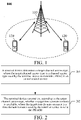
- FIG. shows a communications system 100
- the communications system 100 may include a network device 110.
- the network device 110 may be a device communicating with a terminal device (or referred to as a communications terminal or a terminal) 120.
- the network device 110 may provide communication coverage for a particular geographical area, and may communicate with a terminal device located within the coverage.
- the network device 110 may be a base transceiver station (BTS) in a GSM system or a CDMA system, or may be a NodeB (NB) in a WCDMA system, or may be an evolved NodeB (eNB or eNodeB) in an LTE system, or a radio controller in a cloud radio access network (CRAN), or the network device may be a mobile switching center, a relay station, an access point, an in-vehicle device, a wearable device, a concentrator, a switch, a bridge, a router, a network-side device in a 5G network, a network device in a future evolved public land mobile network (PLMN), or the like.
- BTS base transceiver station
- NB NodeB
- eNB or eNodeB evolved NodeB
- LTE Long Term Evolution
- CRAN cloud radio access network
- the network device may be a mobile switching center, a relay station, an access point, an in-vehi
- the communications system 100 further includes at least one terminal device 120 located within the coverage of the network device 110.
- the "terminal device” used herein includes, but is not limited to, being connected through: a wired line, for example, through a public switched telephone network (PSTN), a digital subscriber line (DSL), a digital cable, or a direct cable; and/or another data connection/network; and/or a radio interface, for example, for a cellular network, a wireless local area network (WLAN), a digital television network such as a DVB-H network, a satellite network, or an AM-FM broadcast transmitter; and/or an apparatus of another terminal device that is configured to receive/send communications signals; and/or an Internet of Things (IoT) device.
- PSTN public switched telephone network
- DSL digital subscriber line
- a digital cable or a direct cable
- a radio interface for example, for a cellular network, a wireless local area network (WLAN), a digital television network such as a DVB-H network,
- a terminal device configured to communicate through a radio interface may be referred to as a "wireless communications terminal", a “wireless terminal”, or a “mobile terminal”.
- the mobile terminal include, but are not limited to, a satellite or a cellular phone; a personal communications system (PCS) terminal that may combine a cellular radio telephone with data processing, a fax, and a data communication capability; a PDA that may include a radio telephone, a pager, Internet/Intranet access, a Web browser, a notepad, a calendar, and/or a Global Positioning System (GPS) receiver; and a regular laptop and/or palmtop receiver or other electronic devices that include a radio telephone transceiver.
- PCS personal communications system
- GPS Global Positioning System
- the terminal device may be an access terminal, user equipment (UE), a subscriber unit, a subscriber station, a mobile station, a mobile console, a remote station, a remote terminal, a mobile device, a user terminal, a terminal, a wireless communications device, a user agent, or a user apparatus.
- UE user equipment
- the access terminal may be a cellular phone, a cordless phone, a Session Initiation Protocol (SIP) phone, a wireless local loop (WLL) station, a personal digital assistant (PDA), a handheld device having a wireless communication function, a computing device, another processing device connected to a wireless modem, an in-vehicle device, a wearable device, a terminal device in a 5G network, a terminal device in a future evolved PLMN, or the like.
- SIP Session Initiation Protocol
- WLL wireless local loop
- PDA personal digital assistant
- the terminal devices 120 may perform device to device (D2D) communication with each other.
- D2D device to device
- the 5G system or the 5G network may also be referred to as an NR system or an NR network.
- FIG. 1 shows one network device and two terminal devices as an example.
- the communications system 100 may include a plurality of network devices, and each network device may cover another quantity of terminal devices.
- the communications system 100 may further include other network entities such as a network controller and a mobility management entity (MME).
- MME mobility management entity
- communications devices may include the network device 110 and the terminal device 120 having a communication function.
- the network device 110 and the terminal device 120 may be specific devices described above, and details are not described herein again.
- the communications devices may further include other devices, for example, other network entities such as the network controller and the MME in the communications system 100.
- FIG. 2 is a schematic flowchart of a channel access method for PRACH transmission according to an embodiment of this application. As shown in FIG. 2 , the method includes the following specific implementation.
- a terminal device determines a target channel access type, where the target channel access type is a channel access type used by the terminal device to transmit a PRACH on an unlicensed carrier.
- the terminal device determines, according to the target channel access type, whether a target time domain resource is available, where the target time domain resource is a time domain resource used by the terminal device to send the PRACH.
- the channel access type may include a type1 channel access type and a type2 channel access type.
- the type1 channel access type is contention window-based channel detection.
- the type1 channel access type includes at least two channel access priorities, and the terminal device may perform channel detection according to channel access parameters corresponding to different priorities.
- a higher channel access priority generally indicates that a channel access time is shorter, but to ensure fairness of spectrum utilization on the unlicensed spectrum, a channel occupation time is also shorter.
- a lower channel access priority generally indicates that the channel access time is longer, but to ensure fairness of spectrum utilization on the unlicensed spectrum, the channel occupation time is also longer.
- the channel access parameters corresponding to the different channel access priorities may be as follows: Table 1 Channel access parameters corresponding to different channel access priorities Channel access priority ( p ) m p CW min , p CW max, p T ulm cot, p Allowed CW p sizes 1 2 3 7 2 ms ⁇ 3,7 ⁇ 2 2 7 15 4 ms ⁇ 7,15 ⁇ 3 3 15 1023 6ms or 10 ms ⁇ 15, 31, 63, 127, 255, 511, 1023 ⁇ 4 7 15 1023 6ms or 10 ms ⁇ 15, 31, 63, 127, 255, 511, 1023 ⁇ 4 7 15 1023 6ms or 10 ms ⁇ 15, 31, 63, 127, 255, 511, 1023 ⁇ 4 7 15 1023 6ms or 10 ms ⁇ 15, 31, 63, 127, 255, 511, 1023 ⁇
- T ulm cot, p 6 ms
- a minimum duration of a gap shall be 100 us.
- a maximum duration before any such gap is included shall be 6 ms.
- specific steps performed by the terminal in channel detection according to the channel access parameters may include:
- An initial value of CWp is CWmin,p, and CWp may be adjusted between CWmin,p and CWmax,p according to a specific condition (for example, transmission fails).
- the type2 channel access type is single slot-based channel detection.
- a type2 channel access procedure includes: performing, by the terminal device before transmission, CCA slot detection with a length of 25 microsecond on the unlicensed spectrum, that is, performing 25-microsecond single slot channel detection. If the channel is idle, it may be considered that the channel access is successful. If the channel is occupied, it may be considered that the channel access fails.
- a terminal device may determine a target channel access type.
- the terminal device determines the target channel access type according to manner 3.
- the terminal device determines the target channel access type according to a standard specification.
- the target channel access type used by the terminal device to transmit the PRACH may be directly stipulated in the standard specification.
- the target channel access type may include at least one of a type1 channel access type with the highest priority, a type2 channel access type, a type1 channel access type with the highest priority with directional channel access, a type2 directional channel access type, and bypassing channel detection.
- a directional channel access type may refer to performing channel detection in a specific direction.
- the type2 directional channel access type may be as follows: The terminal device performs, before transmission, CCA slot detection with a length of 25 microsecond in a specific direction of the unlicensed spectrum, that is, 25-microsecond single slot channel detection. If the channel is idle, it may be considered that the channel access is successful. If the channel is occupied, it may be considered that the channel access fails.
- a non-directional channel access type refers to an omnidirection channel access type.
- bypassing channel detection refers to that the terminal device may send the PRACH in the target time domain resource without channel detection
- the terminal device determines the target channel access type according to a configuration by a network device.
- the network device may first configure some prior information for the terminal device, for example, the PRACH is sent in which time domain resources.
- the network device may further configure the target channel access type for the terminal device.
- the target channel access type may include at least one of a type1 channel access type with the highest priority, a type2 channel access type, a type1 channel access type with the highest priority with directional channel access, a type2 directional channel access type, and bypassing channel detection.
- the terminal device determines the target channel access type according to the target time domain resource.
- the terminal device determines the target channel access type according to whether the target time domain resource belongs to a shared channel occupancy time (shared COT).
- the target channel access type includes at least one of a type1 channel access type with the highest priority, a type2 channel access type, a type1 channel access type with the highest priority with directional channel access, a type2 directional channel access type, and bypassing channel detection.
- the type2 channel access type is used as the target channel access type; otherwise, the type1 channel access type with the highest priority is used as the target channel access type. For another example, if the terminal device determines that the target time domain resource belongs to the shared COT, channel detection is not performed; otherwise, the type2 channel access type is used as the target channel access type.
- channel detection may be not performed. If the terminal device determines that the target time domain resource belongs to a shared COT shared by a network device with the terminal device, the type2 channel access type used as the target channel access type; otherwise, the type1 channel access type with the highest priority used as the target channel access type.
- the shared COT may be a COT shared autonomous uplink (UL) transmission of the terminal device with the target time domain resource.
- UL autonomous uplink
- the shared COT shared by the network device with the terminal device may refer to that the target time domain resource used by the terminal device to transmit the PRACH belongs to a resource in a downlink (DL) transmission opportunity of the network device.
- DL downlink
- the shared COT shared by the autonomous UL transmission of the terminal device with the target time domain resource may refer to that the target time domain resource used by the terminal device to transmit the PRACH belongs to a resource in an autonomous UL transmission opportunity of the terminal device.
- the terminal device determines the target channel access type according to a priority of a service triggering the PRACH to be sent, where the target channel access type is one of at least two candidate channel access types, and the at least two candidate channel access types correspond to the priority of the service triggering the PRACH to be sent.
- the at least two candidate channel access types correspond to the priority of the service triggering the PRACH to be sent.
- a correspondence between the at least two candidate channel access types and the priority of the service triggering the PRACH to be sent is stipulated in a standard specification, or is configured by a network device.
- each service may correspond to a channel access priority.
- the handover service corresponds to the highest channel access priority.
- the correspondence may be a one-to-one correspondence, or may be not a one-to-one correspondence.
- the target channel access type is the channel access type with the highest priority (for example, the type2 channel access type) in the at least two candidate channel access types.
- the target channel access type is the type1 channel access type with the highest priority.
- the network device may configure the correspondence by using radio resource control signaling or the like.
- the at least two candidate channel access types may include at least one of a type1 channel access type with the highest priority, a type2 channel access type, a type1 channel access type with the highest priority with directional channel access, a type2 directional channel access type, and bypassing channel detection.
- the terminal device may determine, according to the target channel access type, whether the target time domain resource is available.
- the target time domain resource is a time domain resource used by the terminal device to send the PRACH.
- the target channel access type is the bypassing channel detection, it may be directly considered that the target time domain resource is available. Otherwise, the terminal device may perform channel detection according to the target channel access type to determine whether the target time domain resource is available according to the target channel access type, that is, channel detection is performed on the unlicensed carrier. If the target time domain resource is available, the PRACH may be sent in the target time domain resource. If the target time domain resource is unavailable, the PRACH is not sent in the target time domain resource.
- a random access procedure corresponding to the PRACH may be a contention-based random access procedure, that is, a CB-RACH procedure, or may be a contention-free random access procedure, that is, a CF-RACH procedure.
- Manners of determining the target channel access type by the terminal device described in the manner 1 to the manner 4 may be applicable to both the contention-based random access procedure and the contention-free random access procedure.
- the terminal device may alternatively determine the target channel access type according to the random access procedure corresponding to the PRACH, where the random access procedure includes the contention-based random access procedure and the contention-free random access procedure.
- the terminal device may determine the target channel access type according to first indication information, where the first indication information is sent to the terminal device by a network device by using physical layer signaling.
- the first indication information may directly indicate the target channel access type, or may indicate a service priority or the like, so that the terminal device determines the target channel access type according to the service priority or the like, or may indicate a channel access priority or the like, so that the terminal device determines, according to the channel access priority or the like, a channel access parameter corresponding to the target channel access type.
- the target channel access type indicated by the first indication information may be determined by the network device according to a priority of a service triggering the PRACH to be sent, or according to whether the target time domain resource belongs to a shared COT.
- the first indication information may be further used for determining at least one of the following information: a start location of the PRACH, an end location of the PRACH, a transmit beam identifier corresponding to the PRACH, and a receive beam identifier corresponding to the PRACH, in addition to indicating the target channel access type and the like.
- the transmit beam identifier corresponding to the PRACH and/or the receive beam identifier corresponding to the PRACH are/is determined according to a beam direction of a synchronization signal block (SSB) associated with a PRACH resource (for example, the target time domain resource).
- the SSB includes primary synchronization signal (PSS), a secondary synchronization signal (SSS), and a physical broadcast channel (PBCH).
- PSS primary synchronization signal
- SSS secondary synchronization signal
- PBCH physical broadcast channel
- the terminal device may determine the target channel access type in the following manner: determining the target channel access type according to a standard specification, or determining the target channel access type according to the a configuration by a network device, or determining the target channel access type according to the target time domain resource.
- the determining, by the terminal device, the target channel access type according to the target time domain resource may include: determining, by the terminal device, the target channel access type according to whether the target time domain resource belongs to a shared COT.
- the target channel access type may include at least one of a type1 channel access type with the highest priority, a type2 channel access type, a type1 channel access type with the highest priority with directional channel access, a type2 directional channel access type, and bypassing channel detection.
- the terminal device may alternatively determine the target channel access type in the following manner: determining, by the terminal device, the target channel access type according to a priority of a service triggering the PRACH to be sent, where the target channel access type is one of at least two candidate channel access types, and the at least two candidate channel access types correspond to the priority of the service triggering the PRACH to be sent.
- the correspondence between the at least two candidate channel access types and the priority of the service triggering the PRACH to be sent is stipulated in a standard specification, or is configured by a network device.
- the at least two candidate channel access types include at least one of a type1 channel access type with the highest priority, a type2 channel access type, a type1 channel access type with the highest priority with directional channel access, a type2 directional channel access type, and bypassing channel detection.
- a network device may send configuration information to a terminal device, so that the terminal device determines a target channel access type according to the configuration information, where the target channel access type is a channel access type used by the terminal device to transmit a PRACH on an unlicensed carrier.
- the configuration information may be the target channel access type, which may include at least one of a type1 channel access type with the highest priority, a type2 channel access type, a type1 channel access type with the highest priority with directional channel access, a type2 directional channel access type, and bypassing channel detection.
- the configuration information may be a correspondence between at least two candidate channel access types and a priority of a service triggering the PRACH to be sent, so that the terminal device determines the target channel access type according to the priority of the service triggering the PRACH to be sent, where the target channel access type is one of the at least two candidate channel access types.
- the correspondence may be a one-to-one correspondence, or may be not a one-to-one correspondence.
- the at least two candidate channel access types include at least one of a type1 channel access type with the highest priority, a type2 channel access type, a type1 channel access type with the highest priority with directional channel access, a type2 directional channel access type, and bypassing channel detection.
- a random access procedure corresponding to the PRACH may be a contention-based random access procedure, that is, a CB-RACH procedure, or may be a contention-free random access procedure, that is, a CF-RACH procedure.
- the foregoing operation of the network device may be applicable to both the contention-based random access procedure and the contention-free random access procedure.
- the network device may further send first indication information to the terminal device by using physical layer signaling, so that the terminal device determines the target channel access type according to the first indication information, where the target channel access type is a channel access type used by the terminal device to transmit the PRACH on the unlicensed carrier.
- the first indication information may directly indicate the target channel access type, or may indicate a service priority or the like, so that the terminal device determines the target channel access type according to the service priority or the like.
- the target channel access type indicated by the first indication information may be determined by the network device according to a priority of a service triggering the PRACH to be sent, or according to whether a target time domain resource belongs to a shared COT.
- the network device may determine the target channel access type according to the priority of the service triggering the PRACH to be sent, where the target channel access type is one of at least two candidate channel access types, and the at least two candidate channel access types correspond to the priority of the service triggering the PRACH to be sent.
- the at least two candidate channel access types may include at least one of a type1 channel access type with the highest priority, a type2 channel access type, a type1 channel access type with the highest priority with directional channel access, a type2 directional channel access type, and bypassing channel detection.
- a corresponding channel access type may be the type2 channel access type.
- the network device may alternatively determine the target channel access type according to whether a target time domain resource belongs to a shared COT.
- the target channel access type may include at least one of a type1 channel access type with the highest priority, a type2 channel access type, a type1 channel access type with the highest priority with directional channel access, a type2 directional channel access type, and bypassing channel detection.
- the type2 channel access type may be used as the target channel access type; otherwise, the type1 channel access type with the highest priority may be used as the target channel access type.
- the first indication information may be further used for determining at least one of the following information: a start location of the PRACH, an end location of the PRACH, a transmit beam identifier corresponding to the PRACH, and a receive beam identifier corresponding to the PRACH, in addition to indicating the target channel access type and the like.
- the PRACH can be sent correctly according to a corresponding channel access type, thereby improving system performance.
- FIG. 3 is a first schematic block diagram of a channel access apparatus for PRACH transmission according to an embodiment of this application. As shown in FIG. 3 , the apparatus includes: a first determining unit 301 and a second determining unit 302.
- the first determining unit 301 is configured to determine a target channel access type, where the target channel access type is a channel access type used by a terminal device to transmit a PRACH on an unlicensed carrier.
- the second determining unit 302 is configured to determine, according to the target channel access type, whether a target time domain resource is available, where the target time domain resource is a time domain resource used by the terminal device to send the PRACH.
- the first determining unit 301 may determine the target channel access type according to a standard specification, or may determine the target channel access type according to a configuration by a network device, or may determine the target channel access type according to the target time domain resource.
- the first determining unit 301 may determine the target channel access type according to whether the target time domain resource belongs to a shared COT.
- the target channel access type includes at least one of a type1 channel access type with the highest priority, a type2 channel access type, a type1 channel access type with the highest priority with directional channel access, a type2 directional channel access type, and bypassing channel detection.
- the first determining unit 301 may alternatively determine the target channel access type according to a priority of a service triggering the PRACH to be sent, where the target channel access type is one of at least two candidate channel access types, and the at least two candidate channel access types correspond to the priority of the service triggering the PRACH to be sent.
- a correspondence between the at least two candidate channel access types and the priority of the service triggering the PRACH to be sent is stipulated in a standard specification, or is configured by a network device.
- the at least two candidate channel access types include at least one of a type1 channel access type with the highest priority, a type2 channel access type, a type1 channel access type with the highest priority with directional channel access, a type2 directional channel access type, and bypassing channel detection.
- a random access procedure corresponding to the PRACH is a contention-based random access procedure or a contention-free random access procedure.
- the first determining unit 301 may alternatively determine the target channel access type according to a random access procedure corresponding to the PRACH, where the random access procedure includes a contention-based random access procedure and a contention-free random access procedure.
- the first determining unit 301 may determine the target channel access type according to first indication information, where the first indication information is sent to the terminal device by a network device by using physical layer signaling.
- the target channel access type indicated by the first indication information is determined by the network device according to a priority of a service triggering the PRACH to be sent, or according to whether the target time domain resource belongs to a shared COT.
- the first indication information may be further used for determining at least one of the following information: a start location of the PRACH, an end location of the PRACH, a transmit beam identifier corresponding to the PRACH, and a receive beam identifier corresponding to the PRACH.
- the first determining unit 301 may determine the target channel access type in the following manner: determining the target channel access type according to a standard specification, or determining the target channel access type according to a configuration by a network device, or determining the target channel access type according to the target time domain resource.
- the determining the target channel access type according to the target time domain resource may include: determining the target channel access type according to whether the target time domain resource belongs to a shared COT.
- the target channel access type includes at least one of a type1 channel access type with the highest priority, a type2 channel access type, a type1 channel access type with the highest priority with directional channel access, a type2 directional channel access type, and bypassing channel detection.
- the first determining unit 301 may alternatively determine the target channel access type in the following manner: determining the target channel access type according to a priority of a service triggering the PRACH to be sent, where the target channel access type is one of at least two candidate channel access types, and the at least two candidate channel access types correspond to the priority of the service triggering the PRACH to be sent.
- a correspondence between the at least two candidate channel access types and the priority of the service triggering the PRACH to be sent is stipulated in a standard specification, or is configured by a network device.
- the at least two candidate channel access types include at least one of a type1 channel access type with the highest priority, a type2 channel access type, a type1 channel access type with the highest priority with directional channel access, a type2 directional channel access type, and bypassing channel detection.
- FIG. 4 is a second schematic block diagram of a channel access apparatus for PRACH transmission As shown in FIG. 4 , the apparatus includes: a first sending unit 401.
- the first sending unit 401 is configured to send configuration information to a terminal device, so that the terminal device determines a target channel access type according to the configuration information, where the target channel access type is a channel access type used by the terminal device to transmit the PRACH on an unlicensed carrier.
- the configuration information may be the target channel access type.
- the configuration information may be a correspondence between at least two candidate channel access types and a priority of a service triggering the PRACH to be sent, so that the terminal device determines the target channel access type according to the priority of the service triggering the PRACH to be sent, where the target channel access type is one of the at least two candidate channel access types.
- FIG. 5 is a third schematic block diagram of a channel access apparatus for PRACH transmission As shown in FIG. 5 , the apparatus includes: a second sending unit 501.
- the second sending unit 501 is configured to send first indication information to a terminal device by using physical layer signaling when a random access procedure corresponding to the PRACH is a contention-free random access procedure, so that the terminal device determines a target channel access type according to the first indication information, where the target channel access type is a channel access type used by the terminal device to transmit the PRACH on an unlicensed carrier.
- the target channel access type indicated by the first indication information is determined according to a priority of a service triggering the PRACH to be sent, or according to whether a target time domain resource belongs to a shared COT.
- the first indication information may be further used for determining at least one of the following information: a start location of the PRACH, an end location of the PRACH, a transmit beam identifier corresponding to the PRACH, and a receive beam identifier corresponding to the PRACH.
- FIG. 3 For specific work procedures of the apparatus shown in FIG. 3, FIG. 4, and FIG. 5 , refer to related descriptions in the foregoing method embodiments. Details are not described herein again.
- FIG. 6 is a schematic structural diagram of a communications device 600
- the communications device 600 shown in FIG. 6 includes a processor 610.
- the processor 610 may invoke a computer program from a memory 620 and run the computer program.
- the communications device 600 may further include the memory 620.
- the processor 610 may invoke the computer program from the memory 620 and run the computer program.
- the memory 620 may be a component independent of the processor 610, or may be integrated into the processor 610.
- the communications device 600 may further include a transceiver 630.
- the processor 610 may control the transceiver 630 to communicate with another device.
- the transceiver 630 may send information or data to the another device, or receive information or data sent by the another device.
- the transceiver 630 may include a transmitter and a receiver.
- the transceiver 630 may further include an antenna, and there may be one or more antennas.
- the communications device 600 may be specifically a network device in the embodiments of this application, and the communications device 600 may implement corresponding procedures implemented by the network device in the methods in the embodiments of this application. For brevity, details are not described herein again.
- FIG. 7 is a schematic structural diagram of a chip a
- the chip 700 shown in FIG. 7 includes a processor 710.
- the processor 710 may invoke a computer program from a memory and run the computer program.
- the chip 700 may further include a memory 720.
- the processor 710 may invoke the computer program from the memory 720 and run the computer program.
- the memory 720 may be a component independent of the processor 710, or may be integrated into the processor 710.
- the chip 700 may further include an input interface 730.
- the processor 710 may control the input interface 730 to communicate with another device or chip, and specifically, may obtain information or data sent by the another device or chip.
- the chip 700 may further include an output interface 740.
- the processor 710 may control the output interface 740 to communicate with another device or chip, and specifically, may output information or data to the another device or chip.
- FIG. 8 is a schematic block diagram of a communications system 800 As shown in FIG. 8 , the communications system 800 includes a terminal device 810 and a network device 820
- the terminal device 810 may be configured to implement corresponding functions implemented by the terminal device in the foregoing method
- the network device 820 may be configured to implement corresponding functions implemented by the network device in the foregoing method.
- the processor may be an integrated circuit chip, and has a signal processing capability.
- steps in the foregoing method embodiments may be completed by using a hardware integrated logical circuit in the processor, or by using instructions in a form of software.
- the processor may be a general-purpose processor, a digital signal processor (DSP), an application-specific integrated circuit (ASIC), a field programmable gate array (FPGA) or another programmable logical device, a discrete gate or transistor logic device, or a discrete hardware component.
- DSP digital signal processor
- ASIC application-specific integrated circuit
- FPGA field programmable gate array
- the methods, the steps, and logical block diagrams that are disclosed in the embodiments of this application may be implemented or performed.
- the general-purpose processor may be a microprocessor or the processor may be any conventional processor or the like.
- Steps of the methods disclosed with reference to the embodiments of this application may be directly performed and accomplished by using a hardware decoding processor, or may be performed and accomplished by using a combination of hardware and software modules in the decoding processor.
- the software modules may be located in a mature storage medium in the field, for example, a random access memory (RAM), a flash memory, a read-only memory (ROM), a programmable ROM (PROM), an electrically erasable programmable memory, or a register.
- the storage medium is located in the memory, and the processor reads information in the memory and completes the steps in the foregoing methods in combination with hardware thereof.
- the memory in this application may be a volatile memory or a non-volatile memory, or may include a volatile memory and a nonvolatile memory.
- the non-volatile memory may be a ROM, a PROM, an erasable PROM (EPROM), an electrically EPROM (EEPROM) or a flash memory.
- the volatile memory may be a RAM, used as an external cache.
- RAMs for example, a static RAM (SRAM), a dynamic RAM (DRAM), a synchronous DRAM (SDRAM), a double data rate SDRAM (DDR SDRAM), an enhanced SDRAM (ESDRAM), a synchlink DRAM (SLDRAM), and a direct rambus RAM (DR RAM), may be used.
- SRAM static RAM
- DRAM dynamic RAM
- SDRAM synchronous DRAM
- DDR SDRAM double data rate SDRAM
- ESDRAM enhanced SDRAM
- SLDRAM synchlink DRAM
- DR RAM direct rambus RAM
- function units in the embodiments of this application may be integrated into one processing unit, or each of the units may exist alone physically, or two or more units are integrated into one unit.
- the functions When the functions are implemented in a form of a software functional module and sold or used as an independent product, the functions may be stored in a computer-readable storage medium.
- the software product is stored in a storage medium, and includes several instructions for instructing a computer device (which may be a personal computer, a server, a network device, or the like) to perform all or some of the steps of the methods described in the embodiments of this application.
- the foregoing storage medium includes: any medium that can store program codes, such as a USB flash drive, a removable hard disk, a ROM, a RAM, a magnetic disk, or an optical disc.
Landscapes
- Engineering & Computer Science (AREA)
- Computer Networks & Wireless Communication (AREA)
- Signal Processing (AREA)
- Mobile Radio Communication Systems (AREA)
Priority Applications (1)
| Application Number | Priority Date | Filing Date | Title |
|---|---|---|---|
| EP22158522.7A EP4030858A1 (en) | 2018-06-20 | 2019-05-23 | Channel access method and apparatus for physical random access channel transmission |
Applications Claiming Priority (2)
| Application Number | Priority Date | Filing Date | Title |
|---|---|---|---|
| CN201810639666 | 2018-06-20 | ||
| PCT/CN2019/088136 WO2019242452A1 (zh) | 2018-06-20 | 2019-05-23 | 用于物理随机接入信道传输的信道接入方法、装置和程序 |
Related Child Applications (1)
| Application Number | Title | Priority Date | Filing Date |
|---|---|---|---|
| EP22158522.7A Division EP4030858A1 (en) | 2018-06-20 | 2019-05-23 | Channel access method and apparatus for physical random access channel transmission |
Publications (3)
| Publication Number | Publication Date |
|---|---|
| EP3749034A1 EP3749034A1 (en) | 2020-12-09 |
| EP3749034A4 EP3749034A4 (en) | 2021-02-24 |
| EP3749034B1 true EP3749034B1 (en) | 2022-03-23 |
Family
ID=68982764
Family Applications (2)
| Application Number | Title | Priority Date | Filing Date |
|---|---|---|---|
| EP19822525.2A Active EP3749034B1 (en) | 2018-06-20 | 2019-05-23 | Channel detection method and apparatus for physical random access channel procedure |
| EP22158522.7A Pending EP4030858A1 (en) | 2018-06-20 | 2019-05-23 | Channel access method and apparatus for physical random access channel transmission |
Family Applications After (1)
| Application Number | Title | Priority Date | Filing Date |
|---|---|---|---|
| EP22158522.7A Pending EP4030858A1 (en) | 2018-06-20 | 2019-05-23 | Channel access method and apparatus for physical random access channel transmission |
Country Status (12)
| Country | Link |
|---|---|
| US (2) | US11051338B2 (pt) |
| EP (2) | EP3749034B1 (pt) |
| JP (1) | JP7301870B2 (pt) |
| KR (1) | KR20210022526A (pt) |
| CN (2) | CN111787636B (pt) |
| AU (1) | AU2019291439B2 (pt) |
| BR (1) | BR112020020924A2 (pt) |
| CA (1) | CA3096565C (pt) |
| ES (1) | ES2912078T3 (pt) |
| MX (1) | MX2020011204A (pt) |
| SG (1) | SG11202009746PA (pt) |
| WO (1) | WO2019242452A1 (pt) |
Families Citing this family (6)
| Publication number | Priority date | Publication date | Assignee | Title |
|---|---|---|---|---|
| CN111787636B (zh) | 2018-06-20 | 2022-11-04 | Oppo广东移动通信有限公司 | 随机接入方法、装置和非易失性存储器 |
| CN111436158B (zh) * | 2019-03-22 | 2023-03-28 | 维沃移动通信有限公司 | 传输物理随机接入信道信号的方法、装置和电子设备 |
| US20220061099A1 (en) * | 2020-08-19 | 2022-02-24 | Qualcomm Incorporated | Synchronization signal block to physical random access channel mapping with multiple resource block sets |
| WO2022061642A1 (en) * | 2020-09-24 | 2022-03-31 | Qualcomm Incorporated | Ue capability report for holographic mimo based initial access |
| WO2023070239A1 (en) * | 2021-10-25 | 2023-05-04 | Qualcomm Incorporated | Sidelink synchronization signal transmission prioritization |
| WO2023130467A1 (zh) * | 2022-01-10 | 2023-07-13 | Oppo广东移动通信有限公司 | 无线通信的方法、终端设备和网络设备 |
Family Cites Families (25)
| Publication number | Priority date | Publication date | Assignee | Title |
|---|---|---|---|---|
| CN100484328C (zh) * | 2006-06-28 | 2009-04-29 | 华为技术有限公司 | 用户终端接入信道的方法及基站节点 |
| KR101527974B1 (ko) * | 2009-04-30 | 2015-06-15 | 엘지전자 주식회사 | 무선통신 시스템에서 상향링크 접속 제어방법 |
| CN101998607B (zh) | 2009-08-31 | 2013-07-31 | 中国移动通信集团公司 | 上行时隙引入下行传输辅同步信号的方法、系统及装置 |
| CN102325382B (zh) | 2011-06-30 | 2016-01-20 | 电信科学技术研究院 | 随机接入方法和设备 |
| CN103249169B (zh) * | 2012-02-03 | 2016-08-31 | 华为技术有限公司 | 传输随机接入应答消息的方法、基站和用户设备 |
| WO2014043857A1 (zh) | 2012-09-19 | 2014-03-27 | 华为技术有限公司 | 信道接入处理方法及其装置 |
| CN103716895B (zh) * | 2012-09-29 | 2020-11-17 | 中兴通讯股份有限公司 | 物理随机接入信道的资源确定方法及装置 |
| CN105532069A (zh) * | 2013-04-28 | 2016-04-27 | 华为技术有限公司 | 物理随机接入信道接入的方法、设备及系统 |
| CN111935720A (zh) | 2014-07-31 | 2020-11-13 | 株式会社Ntt都科摩 | 终端以及无线通信方法 |
| BR112017005864A2 (pt) * | 2014-09-25 | 2018-02-06 | Ericsson Telefon Ab L M | método e aparelho para sinal de referência de uplink aumentado em sistemas de escute antes de falar |
| US10009920B2 (en) | 2015-01-27 | 2018-06-26 | Qualcomm Incorporated | Triggering a group acknowledgement/negative acknowledgement or channel state information |
| KR102612331B1 (ko) * | 2015-01-28 | 2023-12-08 | 인터디지탈 패튼 홀딩스, 인크 | 비면허 대역에서의 lte용 업링크 동작 |
| CN106301733B (zh) * | 2015-06-26 | 2020-11-20 | 中兴通讯股份有限公司 | 数据的传输方法及装置 |
| CN105050189B (zh) | 2015-08-10 | 2019-02-05 | 上海华为技术有限公司 | 一种无线资源调度的方法及相关设备 |
| US10425973B2 (en) | 2015-11-25 | 2019-09-24 | Qualcomm Incorporated | Random access channel signaling on a shared communication medium |
| CN105682232B (zh) * | 2016-01-08 | 2018-03-16 | 宇龙计算机通信科技(深圳)有限公司 | 资源配置方法、资源配置装置和基站 |
| CN105472762B (zh) * | 2016-01-08 | 2019-06-11 | 宇龙计算机通信科技(深圳)有限公司 | 随机接入方法、随机接入装置和终端 |
| US10887912B2 (en) * | 2016-01-20 | 2021-01-05 | Lg Electronics Inc. | Method for transmitting uplink signal and apparatus supporting method in wireless communication system supporting non-licensed band |
| CN105704834B (zh) * | 2016-04-01 | 2019-03-22 | 宇龙计算机通信科技(深圳)有限公司 | 非授权载波上前导码的配置方法、发送方法和相关设备 |
| US10367677B2 (en) | 2016-05-13 | 2019-07-30 | Telefonaktiebolaget Lm Ericsson (Publ) | Network architecture, methods, and devices for a wireless communications network |
| CN107371273B (zh) * | 2016-05-13 | 2023-05-30 | 中兴通讯股份有限公司 | 随机接入方法、装置及用户设备 |
| CN107466112B (zh) | 2016-06-03 | 2022-08-12 | 北京三星通信技术研究有限公司 | 上行数据传输方法、随机接入方法和相应的终端和基站 |
| JP2019216293A (ja) * | 2016-10-11 | 2019-12-19 | シャープ株式会社 | 端末装置、通信方法、および、集積回路 |
| CN108882340A (zh) * | 2017-05-14 | 2018-11-23 | 深圳市金立通信设备有限公司 | 一种免授权频段随机接入方法和设备 |
| CN111787636B (zh) | 2018-06-20 | 2022-11-04 | Oppo广东移动通信有限公司 | 随机接入方法、装置和非易失性存储器 |
-
2019
- 2019-05-23 CN CN202010555142.XA patent/CN111787636B/zh active Active
- 2019-05-23 WO PCT/CN2019/088136 patent/WO2019242452A1/zh unknown
- 2019-05-23 CN CN201980005530.6A patent/CN111295921A/zh active Pending
- 2019-05-23 EP EP19822525.2A patent/EP3749034B1/en active Active
- 2019-05-23 CA CA3096565A patent/CA3096565C/en active Active
- 2019-05-23 ES ES19822525T patent/ES2912078T3/es active Active
- 2019-05-23 KR KR1020207028642A patent/KR20210022526A/ko active Search and Examination
- 2019-05-23 SG SG11202009746PA patent/SG11202009746PA/en unknown
- 2019-05-23 JP JP2020551997A patent/JP7301870B2/ja active Active
- 2019-05-23 MX MX2020011204A patent/MX2020011204A/es unknown
- 2019-05-23 BR BR112020020924-4A patent/BR112020020924A2/pt unknown
- 2019-05-23 AU AU2019291439A patent/AU2019291439B2/en active Active
- 2019-05-23 EP EP22158522.7A patent/EP4030858A1/en active Pending
-
2020
- 2020-09-04 US US17/012,615 patent/US11051338B2/en active Active
-
2021
- 2021-06-03 US US17/338,647 patent/US11968709B2/en active Active
Also Published As
| Publication number | Publication date |
|---|---|
| US11968709B2 (en) | 2024-04-23 |
| US11051338B2 (en) | 2021-06-29 |
| ES2912078T3 (es) | 2022-05-24 |
| WO2019242452A1 (zh) | 2019-12-26 |
| AU2019291439B2 (en) | 2024-04-04 |
| US20200413444A1 (en) | 2020-12-31 |
| CA3096565C (en) | 2023-08-01 |
| SG11202009746PA (en) | 2020-10-29 |
| EP4030858A1 (en) | 2022-07-20 |
| US20210307066A1 (en) | 2021-09-30 |
| JP2021529442A (ja) | 2021-10-28 |
| KR20210022526A (ko) | 2021-03-03 |
| MX2020011204A (es) | 2020-11-13 |
| CN111295921A (zh) | 2020-06-16 |
| CN111787636B (zh) | 2022-11-04 |
| CA3096565A1 (en) | 2019-12-26 |
| BR112020020924A2 (pt) | 2021-02-23 |
| CN111787636A (zh) | 2020-10-16 |
| JP7301870B2 (ja) | 2023-07-03 |
| EP3749034A4 (en) | 2021-02-24 |
| AU2019291439A1 (en) | 2020-10-29 |
| EP3749034A1 (en) | 2020-12-09 |
Similar Documents
| Publication | Publication Date | Title |
|---|---|---|
| EP3749034B1 (en) | Channel detection method and apparatus for physical random access channel procedure | |
| CN112969242B (zh) | 随机接入方法、终端设备、网络设备、芯片及存储介质 | |
| WO2020019230A1 (zh) | 一种资源配置方法及装置、终端设备、网络设备 | |
| US11825519B2 (en) | Random access method, terminal device, network device, and storage medium | |
| US11765743B2 (en) | Downlink channel receiving method and terminal device | |
| WO2019237805A1 (zh) | 一种随机接入方法及装置、通信设备 | |
| CN111935846B (zh) | 传输信号的方法、终端设备和网络设备 | |
| EP4025001A1 (en) | Wireless communication method and apparatus, and communication device | |
| EP3869900A1 (en) | Random access method, terminal device and network device | |
| US12004219B2 (en) | Random access method, terminal device and network device | |
| US11950293B2 (en) | Random access method and terminal device, and network device | |
| WO2020198988A1 (zh) | 一种随机接入方法、电子设备及存储介质 | |
| WO2020186408A1 (zh) | 一种资源管理方法、设备及存储介质 | |
| WO2020061869A1 (zh) | 一种链路恢复方法及装置、通信设备 | |
| JP2021528009A (ja) | チャネルアクセスタイプ指示方法、端末装置及びネットワーク装置 |
Legal Events
| Date | Code | Title | Description |
|---|---|---|---|
| STAA | Information on the status of an ep patent application or granted ep patent |
Free format text: STATUS: THE INTERNATIONAL PUBLICATION HAS BEEN MADE |
|
| PUAI | Public reference made under article 153(3) epc to a published international application that has entered the european phase |
Free format text: ORIGINAL CODE: 0009012 |
|
| STAA | Information on the status of an ep patent application or granted ep patent |
Free format text: STATUS: REQUEST FOR EXAMINATION WAS MADE |
|
| 17P | Request for examination filed |
Effective date: 20200904 |
|
| AK | Designated contracting states |
Kind code of ref document: A1 Designated state(s): AL AT BE BG CH CY CZ DE DK EE ES FI FR GB GR HR HU IE IS IT LI LT LU LV MC MK MT NL NO PL PT RO RS SE SI SK SM TR |
|
| AX | Request for extension of the european patent |
Extension state: BA ME |
|
| A4 | Supplementary search report drawn up and despatched |
Effective date: 20210125 |
|
| RIC1 | Information provided on ipc code assigned before grant |
Ipc: H04W 16/14 20090101ALN20210119BHEP Ipc: H04W 74/08 20090101AFI20210119BHEP Ipc: H04W 74/02 20090101ALN20210119BHEP Ipc: H04W 72/04 20090101ALN20210119BHEP |
|
| REG | Reference to a national code |
Ref country code: DE Ref legal event code: R079 Ref document number: 602019012891 Country of ref document: DE Free format text: PREVIOUS MAIN CLASS: H04W0072040000 Ipc: H04W0074080000 |
|
| DAV | Request for validation of the european patent (deleted) | ||
| DAX | Request for extension of the european patent (deleted) | ||
| GRAP | Despatch of communication of intention to grant a patent |
Free format text: ORIGINAL CODE: EPIDOSNIGR1 |
|
| STAA | Information on the status of an ep patent application or granted ep patent |
Free format text: STATUS: GRANT OF PATENT IS INTENDED |
|
| RIC1 | Information provided on ipc code assigned before grant |
Ipc: H04W 72/04 20090101ALN20210927BHEP Ipc: H04W 16/14 20090101ALN20210927BHEP Ipc: H04W 74/02 20090101ALN20210927BHEP Ipc: H04W 74/08 20090101AFI20210927BHEP |
|
| INTG | Intention to grant announced |
Effective date: 20211022 |
|
| GRAS | Grant fee paid |
Free format text: ORIGINAL CODE: EPIDOSNIGR3 |
|
| GRAA | (expected) grant |
Free format text: ORIGINAL CODE: 0009210 |
|
| STAA | Information on the status of an ep patent application or granted ep patent |
Free format text: STATUS: THE PATENT HAS BEEN GRANTED |
|
| AK | Designated contracting states |
Kind code of ref document: B1 Designated state(s): AL AT BE BG CH CY CZ DE DK EE ES FI FR GB GR HR HU IE IS IT LI LT LU LV MC MK MT NL NO PL PT RO RS SE SI SK SM TR |
|
| REG | Reference to a national code |
Ref country code: GB Ref legal event code: FG4D |
|
| REG | Reference to a national code |
Ref country code: CH Ref legal event code: EP |
|
| REG | Reference to a national code |
Ref country code: DE Ref legal event code: R096 Ref document number: 602019012891 Country of ref document: DE |
|
| REG | Reference to a national code |
Ref country code: IE Ref legal event code: FG4D |
|
| REG | Reference to a national code |
Ref country code: AT Ref legal event code: REF Ref document number: 1478318 Country of ref document: AT Kind code of ref document: T Effective date: 20220415 |
|
| REG | Reference to a national code |
Ref country code: NL Ref legal event code: FP |
|
| REG | Reference to a national code |
Ref country code: ES Ref legal event code: FG2A Ref document number: 2912078 Country of ref document: ES Kind code of ref document: T3 Effective date: 20220524 |
|
| REG | Reference to a national code |
Ref country code: GR Ref legal event code: EP Ref document number: 20220400898 Country of ref document: GR Effective date: 20220509 |
|
| REG | Reference to a national code |
Ref country code: LT Ref legal event code: MG9D |
|
| PG25 | Lapsed in a contracting state [announced via postgrant information from national office to epo] |
Ref country code: SE Free format text: LAPSE BECAUSE OF FAILURE TO SUBMIT A TRANSLATION OF THE DESCRIPTION OR TO PAY THE FEE WITHIN THE PRESCRIBED TIME-LIMIT Effective date: 20220323 Ref country code: RS Free format text: LAPSE BECAUSE OF FAILURE TO SUBMIT A TRANSLATION OF THE DESCRIPTION OR TO PAY THE FEE WITHIN THE PRESCRIBED TIME-LIMIT Effective date: 20220323 Ref country code: NO Free format text: LAPSE BECAUSE OF FAILURE TO SUBMIT A TRANSLATION OF THE DESCRIPTION OR TO PAY THE FEE WITHIN THE PRESCRIBED TIME-LIMIT Effective date: 20220623 Ref country code: LT Free format text: LAPSE BECAUSE OF FAILURE TO SUBMIT A TRANSLATION OF THE DESCRIPTION OR TO PAY THE FEE WITHIN THE PRESCRIBED TIME-LIMIT Effective date: 20220323 Ref country code: HR Free format text: LAPSE BECAUSE OF FAILURE TO SUBMIT A TRANSLATION OF THE DESCRIPTION OR TO PAY THE FEE WITHIN THE PRESCRIBED TIME-LIMIT Effective date: 20220323 Ref country code: BG Free format text: LAPSE BECAUSE OF FAILURE TO SUBMIT A TRANSLATION OF THE DESCRIPTION OR TO PAY THE FEE WITHIN THE PRESCRIBED TIME-LIMIT Effective date: 20220623 |
|
| PG25 | Lapsed in a contracting state [announced via postgrant information from national office to epo] |
Ref country code: LV Free format text: LAPSE BECAUSE OF FAILURE TO SUBMIT A TRANSLATION OF THE DESCRIPTION OR TO PAY THE FEE WITHIN THE PRESCRIBED TIME-LIMIT Effective date: 20220323 Ref country code: FI Free format text: LAPSE BECAUSE OF FAILURE TO SUBMIT A TRANSLATION OF THE DESCRIPTION OR TO PAY THE FEE WITHIN THE PRESCRIBED TIME-LIMIT Effective date: 20220323 |
|
| PG25 | Lapsed in a contracting state [announced via postgrant information from national office to epo] |
Ref country code: SM Free format text: LAPSE BECAUSE OF FAILURE TO SUBMIT A TRANSLATION OF THE DESCRIPTION OR TO PAY THE FEE WITHIN THE PRESCRIBED TIME-LIMIT Effective date: 20220323 Ref country code: SK Free format text: LAPSE BECAUSE OF FAILURE TO SUBMIT A TRANSLATION OF THE DESCRIPTION OR TO PAY THE FEE WITHIN THE PRESCRIBED TIME-LIMIT Effective date: 20220323 Ref country code: RO Free format text: LAPSE BECAUSE OF FAILURE TO SUBMIT A TRANSLATION OF THE DESCRIPTION OR TO PAY THE FEE WITHIN THE PRESCRIBED TIME-LIMIT Effective date: 20220323 Ref country code: EE Free format text: LAPSE BECAUSE OF FAILURE TO SUBMIT A TRANSLATION OF THE DESCRIPTION OR TO PAY THE FEE WITHIN THE PRESCRIBED TIME-LIMIT Effective date: 20220323 Ref country code: CZ Free format text: LAPSE BECAUSE OF FAILURE TO SUBMIT A TRANSLATION OF THE DESCRIPTION OR TO PAY THE FEE WITHIN THE PRESCRIBED TIME-LIMIT Effective date: 20220323 |
|
| PG25 | Lapsed in a contracting state [announced via postgrant information from national office to epo] |
Ref country code: PL Free format text: LAPSE BECAUSE OF FAILURE TO SUBMIT A TRANSLATION OF THE DESCRIPTION OR TO PAY THE FEE WITHIN THE PRESCRIBED TIME-LIMIT Effective date: 20220323 Ref country code: IS Free format text: LAPSE BECAUSE OF FAILURE TO SUBMIT A TRANSLATION OF THE DESCRIPTION OR TO PAY THE FEE WITHIN THE PRESCRIBED TIME-LIMIT Effective date: 20220723 Ref country code: AL Free format text: LAPSE BECAUSE OF FAILURE TO SUBMIT A TRANSLATION OF THE DESCRIPTION OR TO PAY THE FEE WITHIN THE PRESCRIBED TIME-LIMIT Effective date: 20220323 |
|
| REG | Reference to a national code |
Ref country code: CH Ref legal event code: PL |
|
| REG | Reference to a national code |
Ref country code: DE Ref legal event code: R097 Ref document number: 602019012891 Country of ref document: DE |
|
| PLBE | No opposition filed within time limit |
Free format text: ORIGINAL CODE: 0009261 |
|
| STAA | Information on the status of an ep patent application or granted ep patent |
Free format text: STATUS: NO OPPOSITION FILED WITHIN TIME LIMIT |
|
| PG25 | Lapsed in a contracting state [announced via postgrant information from national office to epo] |
Ref country code: MC Free format text: LAPSE BECAUSE OF FAILURE TO SUBMIT A TRANSLATION OF THE DESCRIPTION OR TO PAY THE FEE WITHIN THE PRESCRIBED TIME-LIMIT Effective date: 20220323 Ref country code: LU Free format text: LAPSE BECAUSE OF NON-PAYMENT OF DUE FEES Effective date: 20220523 Ref country code: LI Free format text: LAPSE BECAUSE OF NON-PAYMENT OF DUE FEES Effective date: 20220531 Ref country code: DK Free format text: LAPSE BECAUSE OF FAILURE TO SUBMIT A TRANSLATION OF THE DESCRIPTION OR TO PAY THE FEE WITHIN THE PRESCRIBED TIME-LIMIT Effective date: 20220323 Ref country code: CH Free format text: LAPSE BECAUSE OF NON-PAYMENT OF DUE FEES Effective date: 20220531 |
|
| PGFP | Annual fee paid to national office [announced via postgrant information from national office to epo] |
Ref country code: NL Payment date: 20221227 Year of fee payment: 5 Ref country code: FR Payment date: 20221223 Year of fee payment: 5 |
|
| PGFP | Annual fee paid to national office [announced via postgrant information from national office to epo] |
Ref country code: PT Payment date: 20221226 Year of fee payment: 5 Ref country code: GR Payment date: 20221227 Year of fee payment: 5 Ref country code: BE Payment date: 20221227 Year of fee payment: 5 |
|
| 26N | No opposition filed |
Effective date: 20230102 |
|
| PG25 | Lapsed in a contracting state [announced via postgrant information from national office to epo] |
Ref country code: IE Free format text: LAPSE BECAUSE OF NON-PAYMENT OF DUE FEES Effective date: 20220523 |
|
| PG25 | Lapsed in a contracting state [announced via postgrant information from national office to epo] |
Ref country code: SI Free format text: LAPSE BECAUSE OF FAILURE TO SUBMIT A TRANSLATION OF THE DESCRIPTION OR TO PAY THE FEE WITHIN THE PRESCRIBED TIME-LIMIT Effective date: 20220323 |
|
| PGFP | Annual fee paid to national office [announced via postgrant information from national office to epo] |
Ref country code: IT Payment date: 20221227 Year of fee payment: 5 |
|
| P01 | Opt-out of the competence of the unified patent court (upc) registered |
Effective date: 20230412 |
|
| PGFP | Annual fee paid to national office [announced via postgrant information from national office to epo] |
Ref country code: ES Payment date: 20230621 Year of fee payment: 5 Ref country code: DE Payment date: 20221222 Year of fee payment: 5 |
|
| PGFP | Annual fee paid to national office [announced via postgrant information from national office to epo] |
Ref country code: GB Payment date: 20230523 Year of fee payment: 5 |
|
| REG | Reference to a national code |
Ref country code: AT Ref legal event code: UEP Ref document number: 1478318 Country of ref document: AT Kind code of ref document: T Effective date: 20220323 |
|
| PG25 | Lapsed in a contracting state [announced via postgrant information from national office to epo] |
Ref country code: MK Free format text: LAPSE BECAUSE OF FAILURE TO SUBMIT A TRANSLATION OF THE DESCRIPTION OR TO PAY THE FEE WITHIN THE PRESCRIBED TIME-LIMIT Effective date: 20220323 Ref country code: CY Free format text: LAPSE BECAUSE OF FAILURE TO SUBMIT A TRANSLATION OF THE DESCRIPTION OR TO PAY THE FEE WITHIN THE PRESCRIBED TIME-LIMIT Effective date: 20220323 |